
Process Parameters Optimization of One-Step Spin Forming of Top Cover with Center Flanged Hole
1
Light Alloy Research Institute, Central South University, Changsha 410083, China
2
State Key Laboratory of High Performance and Complex Manufacturing, Central South University, Changsha 410083, China
3
Hunan InnoChina Advanced Materials Co., Yueyang 414021, China
*
Author to whom correspondence should be addressed.
Metals 2023, 13(12), 1920; https://doi.org/10.3390/met13121920
Submission received: 18 October 2023
/
Revised: 2 November 2023
/
Accepted: 11 November 2023
/
Published: 22 November 2023
Abstract
:To assist the low-cost manufacturing of tanks, a one-step method of marginal-restraint mandrel-free spin forming is therefore proposed in this study for the forming of top covers with flanged holes. With the finite element simulation analysis, three different forming strategies are discussed, and the best spinning process is identified. The proposed forming strategies involve preforming the flanged surface first and then preforming the spherical and flanged surfaces in a subsequent trajectory and is proved to have better forming accuracy. Furthermore, the forming quality of the spun parts is improved and optimized by employing more passes, smaller feed ratios, and larger roller fillet radii. It was experimentally verified that the marginal-restraint mandrel-free spinning one-step method with five passes, a feed ratio of 1 mm/r, and a roller fillet radius of 60 mm for the cylindrical roller can achieve accurate forming of a top cover with a center flange hole.
1. Introduction
The top cover is a component of the propellant storage tank structure. The inner contour of the top cover is designed to meet the control requirements of the propellant outflow process, and the forming accuracy is crucial. The traditional method for forming the top cover of a launch vehicle tank with a center flanged hole involves two steps. A preformed cover is first deepened, and a flanged hole is formed by stamping. In this process, corresponding molds are required, and the workpiece needs to be transferred and re-clamped. This process is complex and incurs a high manufacturing cost, long manufacturing time, and risk of rework or scrap formation [1,2]. A typical top cover with a center flanged hole is shown in Figure 1.
For top covers with flanged holes and multiple reverse-curvature bus features, such as that shown in Figure 1, multi-step forming with different processes is still generally adopted. Zhang used a molded spinning method to form domes [3] and explored the instability mechanisms [4,5] in the molded spinning process and the influence of different process parameters such as the feed ratio and roller fillet radius on the forming quality [6,7,8]. The domes and top covers were successfully developed experimentally to meet the forming quality requirements [9,10]. Rao [11] studied the multi-constraint spinning process, and the mechanisms of flange wrinkle instability and thickness variation during the spinning process are discussed in [12,13]. The influence of process parameters such as the spinning trajectory on the forming quality by using mandrel-free spinning was studied [14,15,16]. Experimental dome top cover parts of different shapes and good forming quality were obtained. These studies have mainly focused on single-feature spherical or ellipsoidal domes and the spin forming of top covers. The use of one-step spinning to form the top cover helps reduce costs and avoid accuracy losses caused by secondary clamping. The costs can be further reduced by using mandrel-free spinning [17,18,19].
Common round-hole flanging processes include stamping [20,21,22], electromagnetic forming [23,24], progressive forming [25], single point incremental forming [26,27], and ball spinning flanging [28]. Generally, the manufacturing process for forming the cover involves initially spinning the overall contour and then using a stamping flanging method. In this process, the workpiece that has been spun needs to be transferred to the stamping die, and the secondary setup may incur additional positioning time. This process is time and cost intensive. Single point incremental forming can achieve one-step forming, but it often has limited working range, posing certain challenges for forming large-sized covers. For larger top covers, spinning forming is considered the most economical method. However, as a top cover with a flanged center hole is a multi-featured surface structure in which the top cover surface is combined with a flanged surface, and the center hole has a curvature opposite that of the top cover, the flanging is significantly different from that of flat blanks, and the effect of the center hole flanging on the geometric accuracy of the formed surface of the top cover has rarely been studied. Different forming strategies are available and need to be discussed. Furthermore, the process parameters remain to be determined for the forming accuracy.
In this study, a one-step method for the marginal-restraint mandrel-free spinning of top covers with center flanged holes is presented based on the structural characteristics of top covers. Through this method, top cover spin forming and center hole flange forming can be simultaneously accomplished using the same set of tools on the same equipment, which reduces the manufacturing costs and improves forming efficiency. The method provides a new approach for the subsequent manufacturing processes of anti-curvature busbar parts with multiple features. A finite element model (FEM) of the one-step method was established and experimentally verified, and the influence of different process parameters on the forming quality of the top cover was studied and optimized.
2. One-Step Method for Marginal-Restraint Mandrel-Free Spinning of Top Covers with Center Flanged Holes
The one-step method for the marginal-restraint mandrel-free spin forming of a top cover with a center flange hole is shown in Figure 2. A flat blank with a hole in the center is used, and the outer edge of the blank is fixed to a cylindrical support fixture with a blank-hold ring. To perform the spinning of a top cover with a center flange hole, the blank is rotated by the cylindrical support fixture on a spinning machine table as the cylindrical spinning wheel is fed from the edge of the blank to the center according to the spinning trajectory.
The top cover with a center flanged hole consists of a spherical surface and a flanged surface. The three forming strategies options with different forming orders shown in Figure 3 and Table 1 are investigated. In option 1, the spherical surface is formed first followed by the flanged surface in multiple passes. Specifically, the spherical surface is first formed with spin track A, and the flanged surface is subsequently formed with multiple passes of spin tracks B1 and B2 to Bn. In option 2, the flanged surface is formed first followed by the spherical surface in multiple passes. Specifically, the flanged surface is first formed with spin tracks B1 and B2 to Bn, and then the spherical surface is formed with spin track A. In option 3, the flanged surface is first preformed in multiple passes, and then the spherical and flanged surfaces are simultaneously formed in one pass. Specifically, the flanged surface is preformed with spin trajectories B1 and B2 to Bn−1, and then spin trajectories A and Bn are used to form the spherical and flanged surfaces simultaneously.
The one-step method for the marginal-restraint mandrel-free spinning of top covers with center flanged holes not only allows the use of thin-walled blanks but also eliminates the need for molds. It reduces the processing time and manufacturing cost and cycle time and increases the manufacturing flexibility. Moreover, compared with the multi-step forming method, the errors caused by multiple assemblies are reduced, thereby improving the manufacturing accuracy of the spinning parts.
3. Development and Verification of the Finite Element Model (FEM)
3.1. Development of the FEM
A one-step FEM of a marginal-restraint mandrel-free spinning top cover with a center flanged hole was constructed using the MSC.MARC software 2019 (Hexagon, Stockholm, Sweden). The model is shown in Figure 4. It consists of a blank, a cylindrical support fixture, and a cylindrical roller. The blank has a thickness of 6 mm, a diameter of 820 mm, and a prefabricated hole with a diameter of 90 mm in the center. The mechanical properties are listed in Table 2. The model consists of 7200 eight-node hexahedral solid elements. The cylindrical roller and support fixture were set as rigid bodies, and the blank is set as the deformed body. A dynamic implicit algorithm has been employed. The roller rotational velocity is determined as it is, and there is no mass scaling applied. The friction coefficient is set to be 0.02.
Option 1 in Table 1 was adopted for the roller trajectory in which a spherical surface is first formed in one pass, and then four passes of the spinning trajectory are used to gradually preform flanged holes. The remaining process parameters were set as follows: roller installation angle α = 15°, roller feed ratio = 2 mm/r, roller fillet radius , and blank rotation speed .
Figure 5 shows the equivalent stress distribution in the top cover with a center flange hole. Figure 5a shows that as the spherical surface is being formed, the center area of the blank, i.e., the formed flanged surface area, is subjected to small stress state; the spherical surface is formed first and is affected by the following forming process. Figure 5b shows that as the flanged surface is being spun, the spherical surface is subjected to a higher stress state. Figure 5c shows that the equivalent force of the workpiece is uniformly distributed in a circular band and initially increases, then decreases, and finally increases again from the edge to the center of the workpiece. The maximum equivalent stress occurs at the edge of the flanged hole.
3.2. Verification of the FEM Model
The setting of the spinning test is shown in Figure 6. It is performed through a top cover with a center flange hole using the same process parameters as the simulation and a self-developed spinning machine platform. Figure 7 shows the experimental spinning and forming parts. Both the spherical and flanged surfaces can be formed with good overall forming effect.
The contour and thickness of the experimental parts were measured using the 3D scanner and the thickness measurement instruments shown in Figure 8. The accuracy of the 3D scanner is 0.02 mm, while the accuracy of the thickness measurement instrument is 0.001 mm when measuring thicknesses below 20.00 mm. The experimentally measured thicknesses and contour values are compared with the simulation and theoretical results in Figure 9. The theoretical contour is the envelope of the traveling roller surface. Figure 9a shows that the thickness is slowly reduced at the beginning of the spherical surface and subsequently retains a stable thickness up to the beginning of the flanged surface. It rapidly thins until the end of the flanged hole, at which point the thickness increases slightly. Figure 9b indicates that the spherical surface deviates significantly from the theoretical surface near the flanged surface. The deviation is larger closer to the flanged surface, and the maximum deviation occurs at the beginning of the flanged surface. This is because only the edges of the workpiece were circumferentially constrained, and the material stiffness in the middle area is relatively small. The comparison between the simulation and experimental results shows that the errors between the experimental and simulated parts are acceptable. The maximum thickness error is calculated by Equation (1) to be 4.6%, and the maximum contour error is 5.5%. The FEM can therefore be considered reliable. An optimization of the process parameters needs to be implemented.
where refers to the error, is the simulation results, and is the experiment results.
4. Results and Discussion
As the above process parameters cannot achieve the accurate forming of a top cover with a center-flanged hole, the effects of the process parameters comprising the roller trajectory, trajectory number, feed ratio, and roller fillet radius on the forming pattern are discussed and optimized below. The process parameters were selected and experimentally verified to achieve accurate formation of top covers with center flange holes using the one-step marginal-restraint mandrel-free spinning method.
4.1. Influence of Roller Trajectory on Forming Quality
The effects of the different roller trajectory options in Table 1 on the forming quality of the top cover with a roller feed ratio of = 2 mm/r, roller fillet radius of , and four passes are discussed below.
A comparison of the thicknesses of the spun parts with different roller trajectories is presented in Figure 10. The three manufacturing process options listed in Table 1 result in the same thickness distribution trends as shown in Figure 10a. There are obvious thickness deviations at the transition between the spherical and flanged surfaces, where the thickness of option 1 is significantly smaller than those of options 2 and 3. Figure 10b shows that the minimum thickness occurs for option 2. However, the difference between the minimum thicknesses of the three options is small. The maximum thinning ratio is 29% because the minimum thickness is mainly determined by the maximum expansion amount. Figure 10c shows the maximum thickness difference at the edge of the flanged hole. Here, the thickness difference represents the difference in thickness at the same position coordinates between different forming processes. The maximum difference in thickness, referred to as the maximum thickness difference, occurs at the hole edge. Option 1 resulted in the worst thickness distribution. Option 3 resulted in the smallest thickness difference at the edge of the flanged hole and the best thickness uniformity.
The maximum offset of the contour at the edge of the flanged hole indicates the maximum offset between the contour of the spun part and the theoretical contour at the edge of the flanged hole. A comparison of the spun parts and theoretical contours is shown in Figure 11. The spun contours of the three options agree well with the theoretical contours in the spherical surface section. In the flanged surface section, the difference between the spun and theoretical contours of the three options is more obvious. The maximum offsets of the spun part contour for options 1, 2, and 3 are 2.67, 10.52, and 1.36 mm, respectively. The maximum offset of 0.25 mm for the edge contour of the flanged hole for option 3 is significantly smaller than those for options 1 and 2.
Considering the thicknesses and contour accuracies obtained with the different roller trajectories, the best contour accuracy and thickness uniformity can be obtained by using option 3. In other words, the optimal roller trajectory is to adopt multiple spin trajectories to preform the flanged surface first and then to employ the last trajectory to achieve simultaneous spin forming of the spherical and flanged surfaces.
Option 3 was adopted for the roller trajectory, and a feed ratio of 2 mm/r and roller fillet radius of 60 mm were used to study the effects of three, four, and five passes on the forming quality of top covers with center flanged holes.
In the option 3 roller spinning trajectory, the flanged surface is first formed over multiple spinning passes, and the simultaneous spinning of the spherical and flanged surfaces is realized in the last trajectory pass. Because the last trajectory is fixed, the number of passes here refers to the passes for preforming the flanged surface. The parameters for the trajectories with three, four, and five passes are listed in Table 3.
The effect of passes, feed ratio, and roller fillet radius have been investigated by simulation in detail. Firstly, as shown in Figure 12, the number of the passes mainly affects the thickness at the beginning of the flanged surface. The minimum thickness occurs near the edge of the flanged hole; more passes resulted in a larger minimum thickness of the spun part and a smaller thickness difference at the edge of the flanged hole. For three passes, the minimum thickness of the spun part is 4.211 mm, and the maximum thickness difference at the edge of the flanged hole is 0.044 mm. For five passes, the minimum thickness of the spun part is 4.274 mm, and the maximum thickness difference at the edge of the flanged hole is 0.019 mm. Increasing the number of passes can increase the minimum thickness of the spun part and improve the thickness uniformity at the edge of the flanged hole.
As shown in Figure 13, the number of passes has the most significant effect on the contour of the spun part at the starting position of the flanged surface, while the contours at the remaining portions agree well with the theoretical contour. More passes resulted in smaller maximum contour offsets and offsets of the edge of the flanged hole. For three passes, the maximum offset of the contour is 1.87 mm, and the maximum offset of the edge of the flanged hole is 0.34 mm. For five passes, the maximum offset of the contour is 1.12 mm, and the maximum offset of the edge of the flanged hole is 0.19 mm. These results show that increasing the number of passes can improve the contour accuracy of the spun part and the roundness of the flanged hole.
4.2. Influence of Feed Ratio on Forming Quality
A top cover with a center flanged hole in which the flanged hole was preformed over two passes is shown in Figure 14. The spherical and flanged surfaces spins are formed simultaneously in the final pass. However, several obvious cracks were observed at the edges of the flanged holes. These cracks resulted from the large amount of deformation in each pass, which exceeded the elongation limit of the material. The influence of the feed ratio is discussed as follows.
Option 3 and four passes were adopted for the roller trajectory and a roller fillet radius of 60 mm used to study the effects of feed ratios of 1, 2, and 4 mm/r on the forming quality of top covers with center flanged holes. As shown in Figure 15, the feed ratio mainly affected the thickness of the spun part at the beginning of the flanged surface. The minimum thickness occurs near the edge of the flanged hole. Larger feed ratios resulted in larger differences between the minimum thickness of the spun part and the thickness of the edge of the flanged hole. For the feed ratio of 1 mm/r, the minimum thickness of the spun part is 4.234 mm, and the thickness difference at the edge of the flanged hole is 0.017 mm. For the feed ratio of 4 mm/r, the minimum thickness of the spun part is 4.323 mm, and the thickness difference at the edge of the flanged hole is 0.047 mm. A large feed ratio can increase the minimum thickness of the spun part but also reduces the thickness uniformity at the edge of the flanged hole.
As shown in Figure 16, the feed ratio has the most significant effect on the contour of the spun part at the beginning of the flanged surface, while the remainder of the part agrees well with the theoretical contour. Larger feed ratios resulted in larger maximum offsets of the spun part and flanged hole edge contours. The maximum offset of the flanged hole edge contour is increased significantly as the feed ratio is increased from 2 to 4 mm/r. For the feed ratio of 1 mm/r, the maximum offset of the contour is 1.17 mm, and that of the flanged hole edge contour is 0.21 mm. For the feed ratio of 4 mm/r, the maximum offset of the contour is 1.93 mm, and that of the flanged hole edge contour is 0.59 mm. These results indicate that a small feed ratio can improve the accuracy of the spun part contour and the roundness of the flanged hole.
4.3. Influence of Roller Fillet Radius on Forming Quality
Option 3 with four passes was adopted for the roller trajectory at a feed ratio of 2 mm/r to study the effects of roller fillet radii of 40, 50, and 60 mm on the forming quality of top covers with center flanged holes. As shown in Figure 17, the roller fillet radius has the most significant effect on the thickness of the spun part at the beginning of the flanged surface, while the remainder of the part has better fit. Larger roller fillet radii resulted in larger minimum thicknesses of the spun part and smaller thickness differences at the edge of the flanged hole. For the roller fillet radius of 40 mm, the minimum thickness of the spun part is 3.372 mm, and the thickness difference at the edge of the flanged hole is 0.056 mm. For the roller fillet radius of 60 mm, the minimum thickness of the spun part is 4.253 mm, and the thickness difference at the edge of the flanged hole is 0.031 mm. The uniformity of the thickness at the edge of the flanged hole can be improved.
As shown in Figure 18, the roller fillet radius has the most significant effect on the contour of the spun part at the beginning of the flanged surface, while the remainder of the part has better fit. Larger roller fillet radii resulted in smaller maximum offsets between the contours of the spun part and the edge of the flanged hole. For the roller fillet radius of 40 mm, the maximum contour offset is 1.51 mm, and the maximum offset of the flanged hole edge is 0.46 mm. For the roller fillet radius of 60 mm, the maximum contour offset is 1.36 mm, and the maximum offset of the flanged hole edge is 0.25 mm. The accuracy of the spun part contour and the roundness of the flanged hole can therefore be improved by using a larger fillet radius.
4.4. Experimental Verification
Based on the above results, we chose roller trajectory option 3 with five passes, a feed ratio of = 4 mm/r, and a roller fillet radius of to obtain the best contour and thickness accuracies. The experimental platform for spin forming top covers with center flanged holes is shown in Figure 19. The platform has a single roller arrangement with a cylindrical roller and a roller installation angle of 15°. A 2219-O state aluminum alloy plate with the dimensions of 820 mm × 820 mm, a thickness of 6 mm, and a prefabricated hole with a diameter of 90 mm in the center was used as the experimental blank.
The forming process of the specimen is shown in Figure 20. The experimental piece of the top cover under the optimized parameters is shown in Figure 21. The experimental piece is well formed, and an ultrasonic thickness gauge was used to measure the thickness of the spun part along the busbar direction. A 3D scanner was used to scan the spun part, and the scanning results were imported to obtain a 3D model of the spun part. The model is shown in Figure 21a. The contour data of the scanned model for the spun part were extracted along the path shown in Figure 21b. The thickness and contour are compared with the simulation values.
The thickness of the manufactured top cover is measured along the path shown in Figure 22. A comparison of the thickness of the experimental part with the simulation thickness is shown in Figure 23. The thickness of the spherical surface section initially decreases and then increases as the spin-forming angle decreases. The thickness of the flanged surface section decreases with increasing expansion but increases slightly at the edge of the flanged hole. The thickness distribution of the experimental part is consistent with the simulation results. The maximum thickness deviation is 0.07 mm. The minimum thicknesses of the experimental part and at the edge of the flanged hole are 4.24 and 4.42 mm, respectively. The thickness requirements for the top cover with a center flanged hole are therefore satisfied.
A comparison of the experimental, simulated, and theoretical contours is presented in Figure 24. It can be seen that the distributions of the experimental, simulated, and theoretical contours agree well. The maximum contour offset between the experimental and simulated contours is 0.15 mm, and the maximum contour offset from the theoretical contour is 0.89 mm, which is within the contour accuracy requirements. These results show that accurate spin forming of top covers with center flanged holes can be achieved using the one-step marginal-restraint mandrel-free spinning method with the optimized parameters (roller trajectory option 3, five passes, feed ratio of 4 mm/r, roller fillet radius of 60 mm).
5. Conclusions
A one-step method for marginal-restraint mandrel-free spinning was proposed in this paper to perform the integral forming of top covers with center flanged holes based on their structural characteristics. The finite element method was used to study the influence of the roller trajectory, trajectory number, feed ratio, and roller fillet radius on the forming quality. The best forming quality is achieved by adopting a trajectory option in which the flanged surface is first preformed in multiple passes and the spherical and flanged surfaces subsequently formed in one pass. The forming quality of the spun parts can be improved by using larger trajectory numbers and roller fillet radii and smaller feed ratios. Precise forming of top covers with center flanged holes can be achieved using the marginal-restraint mandrel-free spinning one-step method with trajectory option 3, five passes, a feed ratio of 1 mm/r, and a cylindrical roller fillet with a radius of 60 mm. The integral spin forming of top covers with center flanged holes using the one-step method was experimentally verified, and the optimized parameters are proven to be effective on the precision forming of the specimen.
This study primarily ensured the precise formation of top covers with a central flange hole. The geometry and thicknesses of these covers were well preserved after optimizing the process parameters. Throughout the manufacturing process, the evolution of material structure and performance played a crucial role. In future research, we will further investigate the aluminum alloy material’s structural evolution and its relationship with process parameters during the spinning process.
Author Contributions
L.Z., C.H., X.L. and X.C. conceived the study; L.Z., X.L. and X.C. designed the experiments; L.Z., J.Y. and X.C. performed the experiments; L.Z. and J.Y. analyzed the data; L.Z., C.H., X.L., J.Y. and X.C. wrote the first draft of the manuscript; C.H., X.C. and J.Y. reviewed and edited the manuscript. All authors have read and agreed to the published version of the manuscript.
Funding
This research was funded by a project (2020YFA0711104) supported by the National Key Research and Development Program of China. and project 933A2AB1 supported by Research on Innovative Application of Aerospace Science and Technology, China Academy of Launch Vehicle Technology.
Institutional Review Board Statement
Not applicable.
Informed Consent Statement
Not applicable.
Data Availability Statement
The data presented in this study are available on request from the corresponding author. The data are not publicly available due to project confidentiality.
Conflicts of Interest
The authors declare no conflict of interest. The funders had no role in the design of the study; in the collection, analyses, or interpretation of data; in the writing of the manuscript; or in the decision to publish the results.
References
- Music, O.; Allwood, J.M.; Kawai, K. A review of the mechanics of metal spinning. J. Mater. Process. Technol. 2010, 210, 3–23. [Google Scholar] [CrossRef]
- Markus, B.; Holger, V.; Gerhard, H. A New Process Design for Performing Hole-flanging Operations by Incremental Sheet Forming. Procedia Eng. 2014, 281, 2305–2310. [Google Scholar] [CrossRef]
- Zhang, Y.Q.; Shan, D.B.; Xu, W.C.; Lv, Y. Study on Spinning Process of a Thin-Walled Aluminum Alloy Vessel Dome With Small Ratio of Thickness to Diameter. J. Manuf. Sci. Eng. 2010, 132, 014504. [Google Scholar] [CrossRef]
- Li, Z.X.; Zhan, M.; Fan, X.G.; Dong, Y.D.; Xu, L.P. Effect of blank quenching on shear spinning forming precision of 2219 aluminum alloy complex thin-walled components. Chin. J. Aeronaut. 2022, 36, 538–555. [Google Scholar] [CrossRef]
- Chen, S.W.; Zhan, M.; Gao, P.F.; Ma, F.; Zhang, H.R. A new robust theoretical prediction model for flange wrinkling in conventional spinning. J. Mater. Process. Technol. 2021, 288, 116849. [Google Scholar] [CrossRef]
- Yu, Z.; Zhao, Y.; Du, C.; Liu, D.F.; Evsyukov, S.A. Study on flange-constrained spinning process for hemispherical aluminum alloy part. J. Mater. Process. Technol. 2020, 278, 116515. [Google Scholar] [CrossRef]
- Gan, T.; Jun, N.; Yu, Z.Q.; Zhao, Y.X.; Li, S.H. Study on warm formability of aluminum alloy 2219 in hemispherical part conventional spinning. Procedia Manuf. 2020, 50, 45–50. [Google Scholar] [CrossRef]
- Watson, M.; Long, H. Wrinkling Failure Mechanics in Metal Spinning. Procedia Eng. 2014, 81, 2391–2396. [Google Scholar] [CrossRef]
- Zhang, H.R.; Zhan, M.; Zheng, Z.B.; Li, R.; Ma, F.; Cui, X.; Chen, S.; Lei, Y. Forming dependence on spin roller paths for thin-walled complex components from 2195 Al-Li alloy TWBs. Int. J. Adv. Manuf. Technol. 2022, 120, 3113–3122. [Google Scholar] [CrossRef]
- Zhan, M.; Yang, H.; Zhang, J.H.; Xu, Y.L.; Ma, F. 3D FEM analysis of influence of roller feed rate on forming force and quality of cone spinning. J. Mater. Process. Technol. 2007, 187, 486–491. [Google Scholar] [CrossRef]
- Rao, G.J.; Li, X.H.; Zhou, L.; Chang, S.W.; Cao, Q.; Yi, Z.X. A multi-constraint spinning process of ellipsoidal domes. Int. J. Adv. Manuf. Technol. 2018, 94, 1505–1512. [Google Scholar] [CrossRef]
- Liu, B.M.; Gao, S.; Jia, Z.; Wen, Y.Z.; Han, Z.R.; Gong, X. Non-axisymmetric die-less spinning using ball-crown-shape roller. Manuf. Process 2022, 79, 70–80. [Google Scholar] [CrossRef]
- Lin, Y.C.; Chen, J.Y.; He, D.G.; Li, X.H.; Yang, J. Marginal-restraint mandrel-free spinning process for thin-walled ellipsoidal domes. Adv. Manuf. 2020, 8, 189–203. [Google Scholar] [CrossRef]
- Jia, Z.; Ye, T.; Han, Z.; Han, Z.R.; Xiao, Y.; Ji, S.D. Study on die-less spinning of cone–cylinder combined hollow parts. J. Mater. Process. Technol. 2019, 271, 488–498. [Google Scholar] [CrossRef]
- Li, L.B.; Chen, S.Y.; Lu, Q.Y.; Shu, X.D.; Zhang, J.; Shen, W.W. Effect of Process Parameters on Spinning Force and Forming Quality of Deep Cylinder Parts in Multi-Pass Spinning Process. Metals 2023, 13, 620. [Google Scholar] [CrossRef]
- Peng, H.L.; Li, M.Z.; Liu, C.G.; Fu, W.Z.; Cao, J.H. Numerical simulation of multi-point forming accuracy for polycarbonate sheet. Arch. Proc. Inst. Mech. Eng. Part E J. Process Mech. Eng. 2013, 228, 87–96. [Google Scholar] [CrossRef]
- Xia, Q.X.; Xiao, G.F.; Long, H.; Cheng, X.Q.; Sheng, X.F. A review of process advancement of novel metal spinning. Int. J. Mach. Tools Manuf. 2014, 85, 100–121. [Google Scholar] [CrossRef]
- Huang, K.; Yi, Y.P.; Huang, S.Q.; He, H.L.; Dong, F.; Jia, Y.Z.; Yu, W.W. Cryogenic die-less spinning of aluminum alloy thin-walled curved components and microstructure evolution. J. Manuf. Process. 2023, 92, 32–41. [Google Scholar] [CrossRef]
- Yan, X.G.; Zhan, M.; Wang, Y.; Gao, P.F.; Wang, Y.D. Criterion and processing-dependence of forming states in the die-less spinning of conical part. Int. J. Adv. Manuf. Technol. 2023, 125, 3037–3051. [Google Scholar] [CrossRef]
- Krichen, A.; Kacem, A.; Hbaieb, M. Blank-holding effect on the hole-flanging process of sheet aluminum alloy. J. Mater. Process. Technol. 2011, 211, 619–626. [Google Scholar] [CrossRef]
- Ou, H.; Sun, S.J.; Li, P.F.; Li, G.Y.; Cui, J. A dynamic small-sized hole flanging process driven by Lorentz-force for aluminum alloys. Int. J. Mater. Form. 2021, 14, 1019–1030. [Google Scholar] [CrossRef]
- Yogesh, D.W.; Rajesh, P.; Nitin, T. A study on sheet metal hole-flanging process. Mater. Today 2017, 4, 5421–5428. [Google Scholar] [CrossRef]
- Li, M.; Lai, Z.P.; Xu, W.; Zheng, Y.; Zhang, Z.X.; Li, C.X.; Gao, Y.H.; Wang, Z.Y.; Cao, Q.L.; Han, X.T.; et al. A versatile electromagnetic actuator for sheet and tube flanging: Process principle, simulation, and experimental validation. J. Manuf. Process. 2022, 81, 311–327. [Google Scholar] [CrossRef]
- Su, H.L.; Huang, L.; Li, J.; Li, J.J.; Ma, F.; Ma, H.J.; Huang, P.; Zhu, H.; Feng, F. Inhomogeneous deformation behaviors of oblique hole-flanging parts during electromagnetic forming. J. Manuf. Process. 2020, 52, 1–11. [Google Scholar] [CrossRef]
- Thipprakmas, S.T.; Jin, M.; Murakawa, M. Study on flanged shapes in fineblanked-hole flanging process (FB-hole flanging process) using finite element method (FEM). J. Mater. Process. Technol. 2007, 192, 128–133. [Google Scholar] [CrossRef]
- Cui, Z.; Gao, L. Studies on hole-flanging process using multistage incremental forming. CIRP J. Manuf. Sci. Technol. 2010, 2, 124–128. [Google Scholar] [CrossRef]
- Centeno, G.; Silva, M.B.; Cristino, V.A.M.; Vallellano, C.; Martins, P.A.F. Hole-flanging by incremental sheet forming. Int. J. Mach. Tools Manuf. 2012, 59, 46–54. [Google Scholar] [CrossRef]
- Elmasry, M.; Elmetwally, H.T.; El-Sheikh, M.N.; Abdel-Magied, R.K. An experimental and analytical investigation of flange forming by spinning process. J. Comput. Appl. Res. Mech. Eng. (JCARME) 2021, 11, 35–46. [Google Scholar] [CrossRef]
Figure 1.
Tank dome with the top cover.
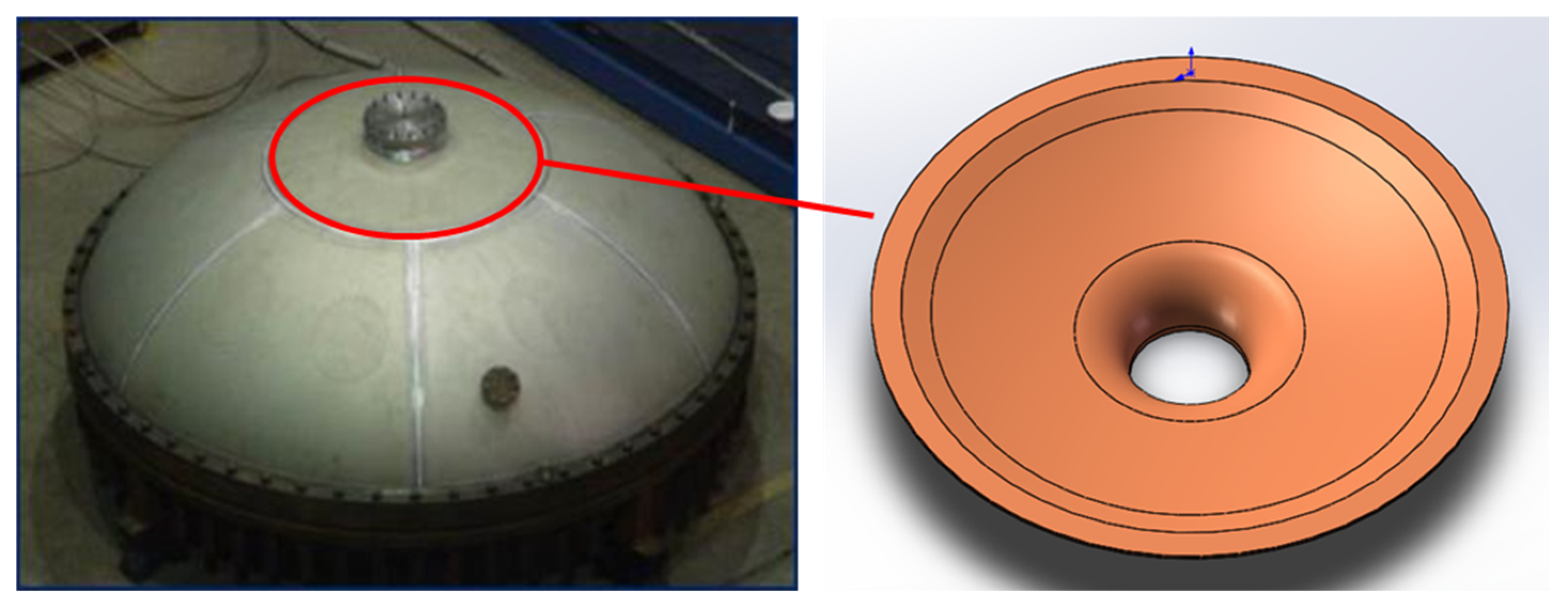
Figure 2.
One-step method for marginal-restraint mandrel-free spinning of top cover with center flange hole.
Figure 2.
One-step method for marginal-restraint mandrel-free spinning of top cover with center flange hole.
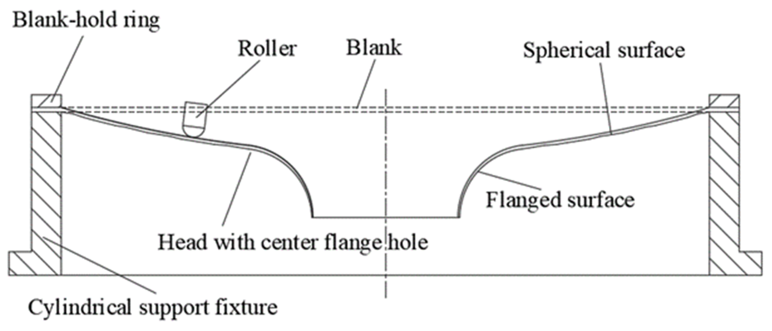
Figure 3.
Schematic diagram of punching-spinning flanging process.
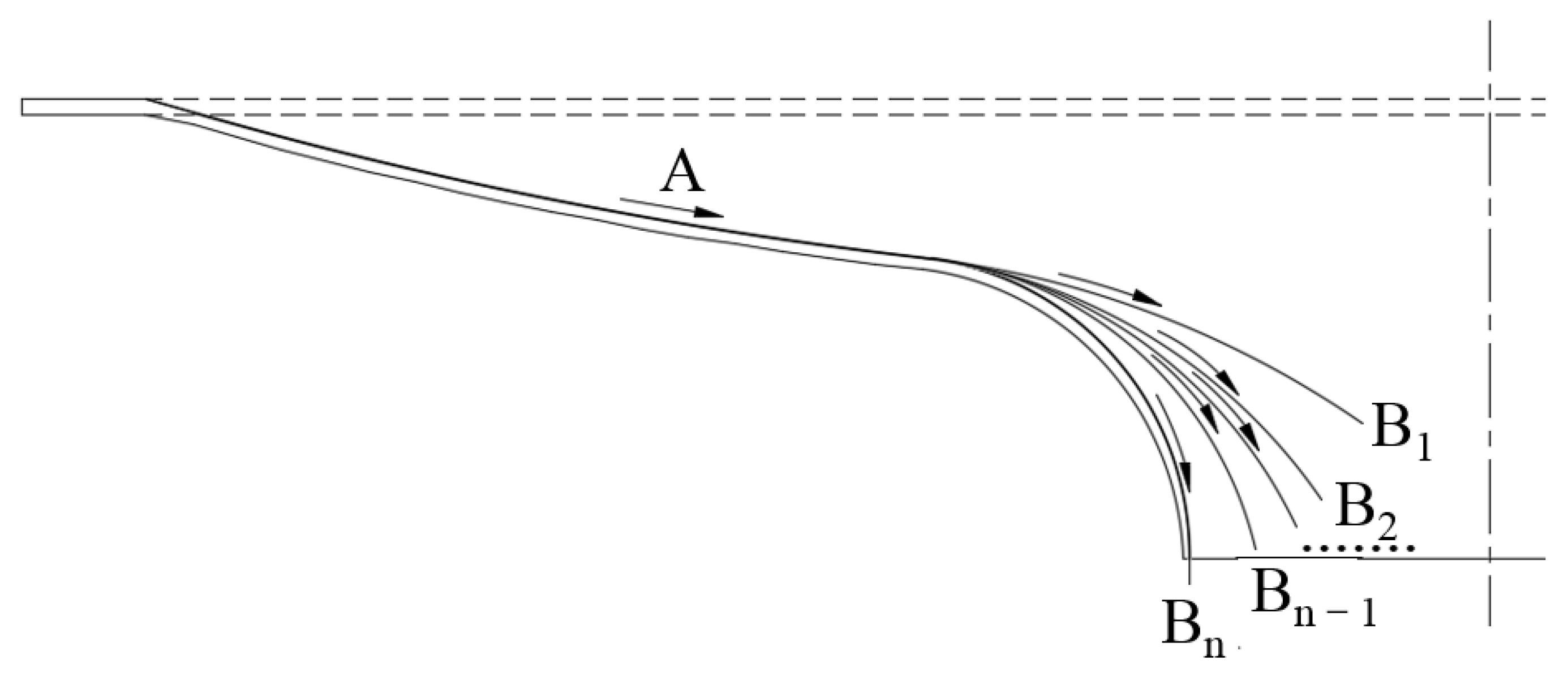
Figure 4.
FEM of punching-spinning flanging.
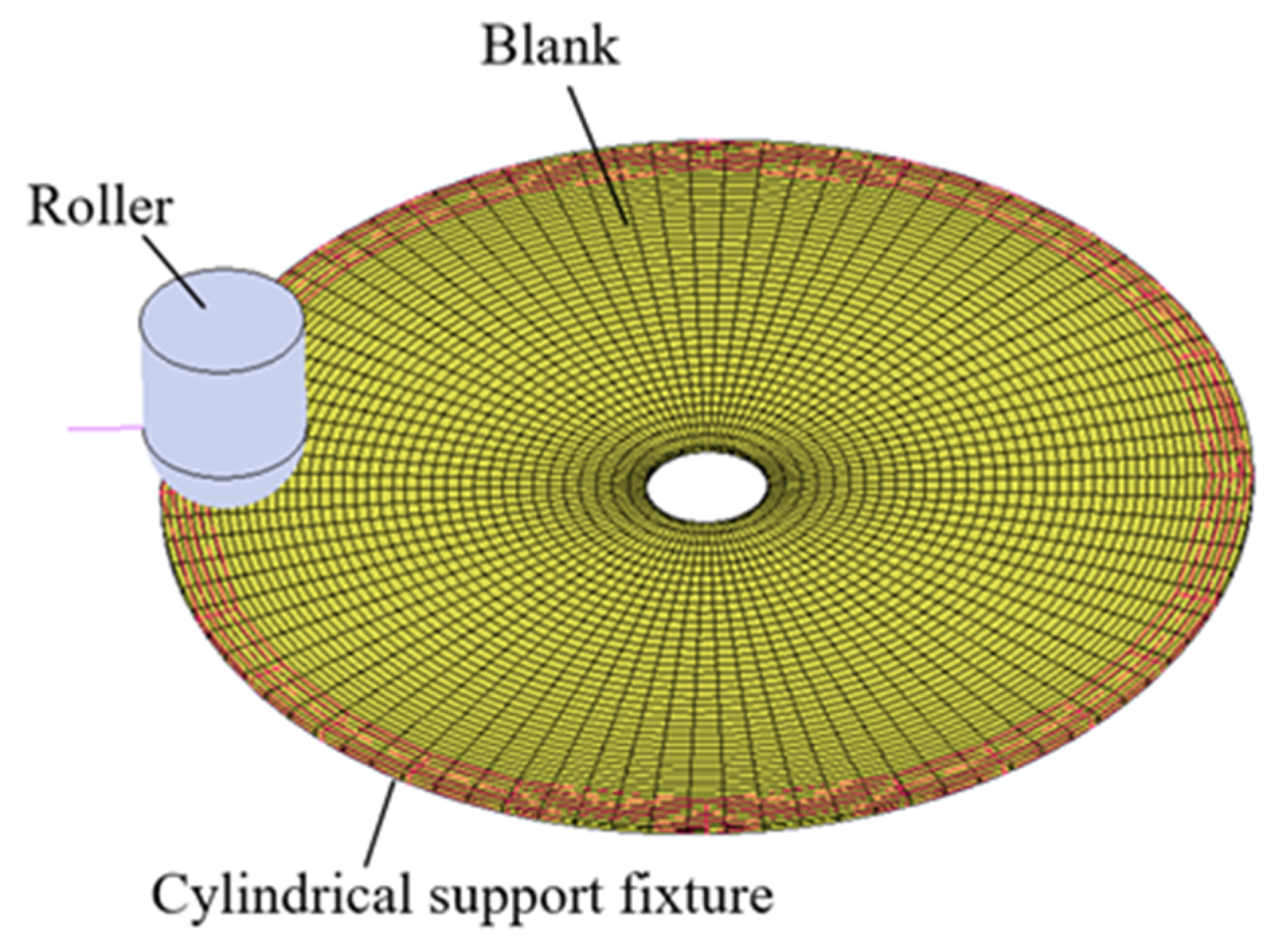
Figure 5.
The equivalent stress distribution of the top cover during the forming process: (a) Stress distribution while the spherical surface is forming. (b) Stress distribution while the flanged surface is forming. (c) Stress distribution while the flanged center hole is forming.
Figure 5.
The equivalent stress distribution of the top cover during the forming process: (a) Stress distribution while the spherical surface is forming. (b) Stress distribution while the flanged surface is forming. (c) Stress distribution while the flanged center hole is forming.

Figure 6.
Spinning experiment platform and the setting of the blank.
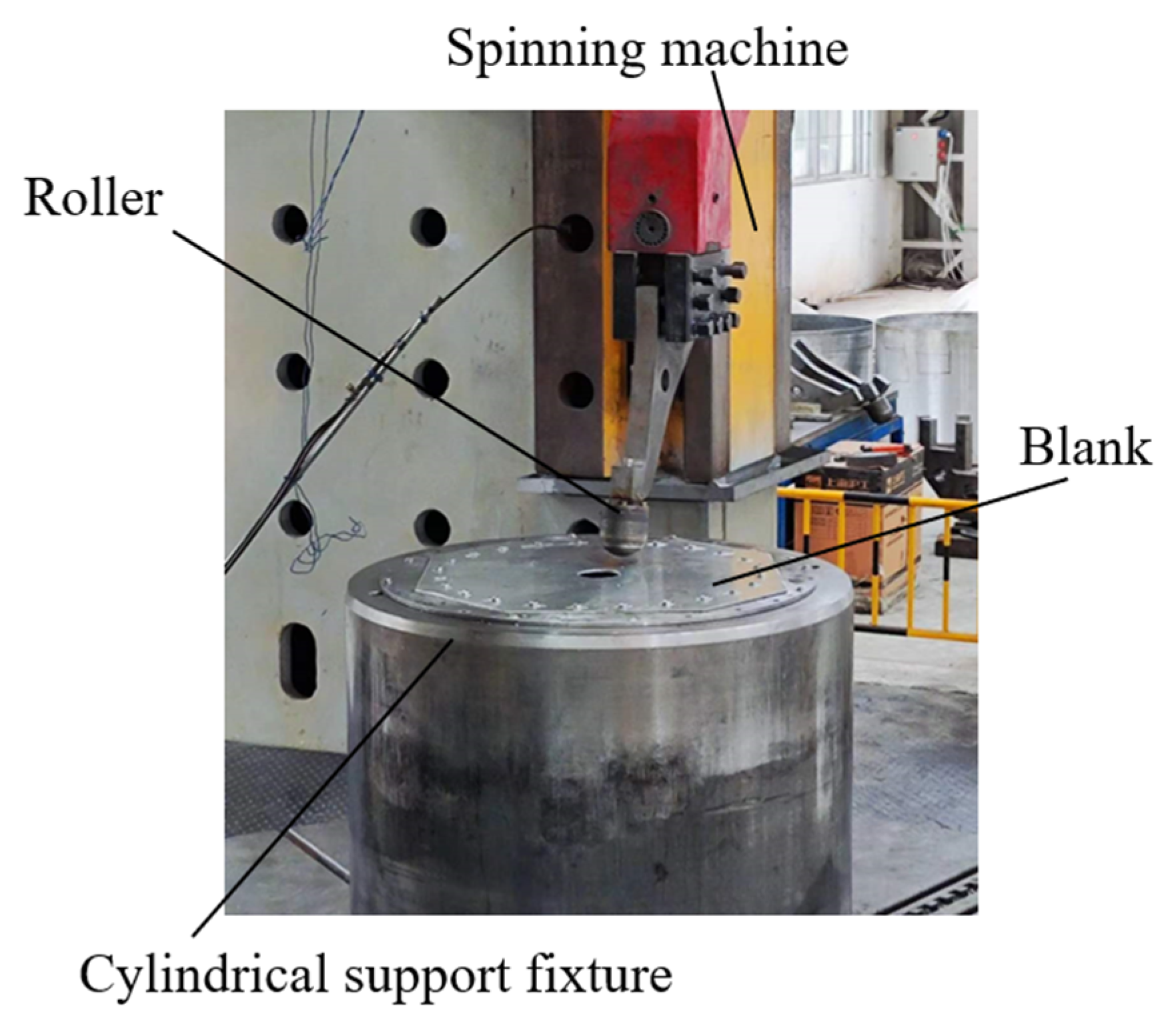
Figure 7.
Experimental specimen obtained for FEM verification. (a) From the top view. (b) From the side view.
Figure 7.
Experimental specimen obtained for FEM verification. (a) From the top view. (b) From the side view.

Figure 8.
Testing equipment. (a) Dakota PX-7 ultrasonic thickness gauge. (b) AXE-B17 3D scanner.

Figure 9.
Comparison of measurement results for experimental parts. (a) Thickness comparison. (b) Contour comparison.
Figure 9.
Comparison of measurement results for experimental parts. (a) Thickness comparison. (b) Contour comparison.
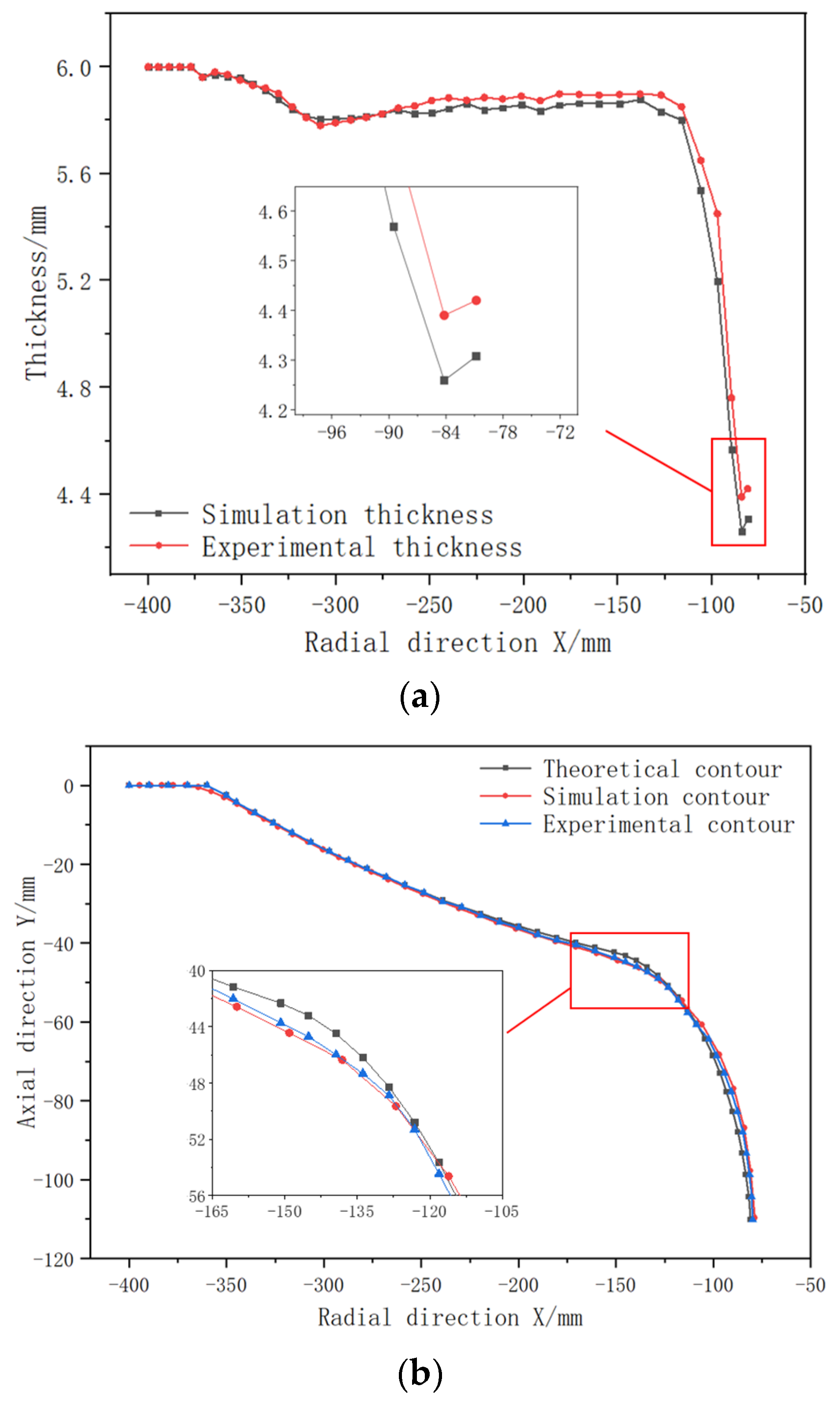
Figure 10.
Influence of roller trajectory on thickness accuracies of spun parts. (a) Comparison of thicknesses of spun parts. (b) Minimum thickness. (c) Flanged hole edge maximum thickness difference.
Figure 10.
Influence of roller trajectory on thickness accuracies of spun parts. (a) Comparison of thicknesses of spun parts. (b) Minimum thickness. (c) Flanged hole edge maximum thickness difference.

Figure 11.
Influence of roller trajectory on forming quality. (a) Comparison of spun and theoretical contours. (b) Maximum contour offset. (c) Maximum offset of flanged hole edge contour.
Figure 11.
Influence of roller trajectory on forming quality. (a) Comparison of spun and theoretical contours. (b) Maximum contour offset. (c) Maximum offset of flanged hole edge contour.

Figure 12.
Influence of passes on thickness accuracies of spun parts. (a) Comparison of thicknesses of spun parts. (b) Minimum thicknesses. (c) Flanged hole edge maximum thickness differences.
Figure 12.
Influence of passes on thickness accuracies of spun parts. (a) Comparison of thicknesses of spun parts. (b) Minimum thicknesses. (c) Flanged hole edge maximum thickness differences.

Figure 13.
Influence of passes on contour accuracies of spun parts. (a) Comparison of spun and theoretical contours. (b) Maximum contour offset. (c) Maximum offset of flanged hole edge contour.
Figure 13.
Influence of passes on contour accuracies of spun parts. (a) Comparison of spun and theoretical contours. (b) Maximum contour offset. (c) Maximum offset of flanged hole edge contour.
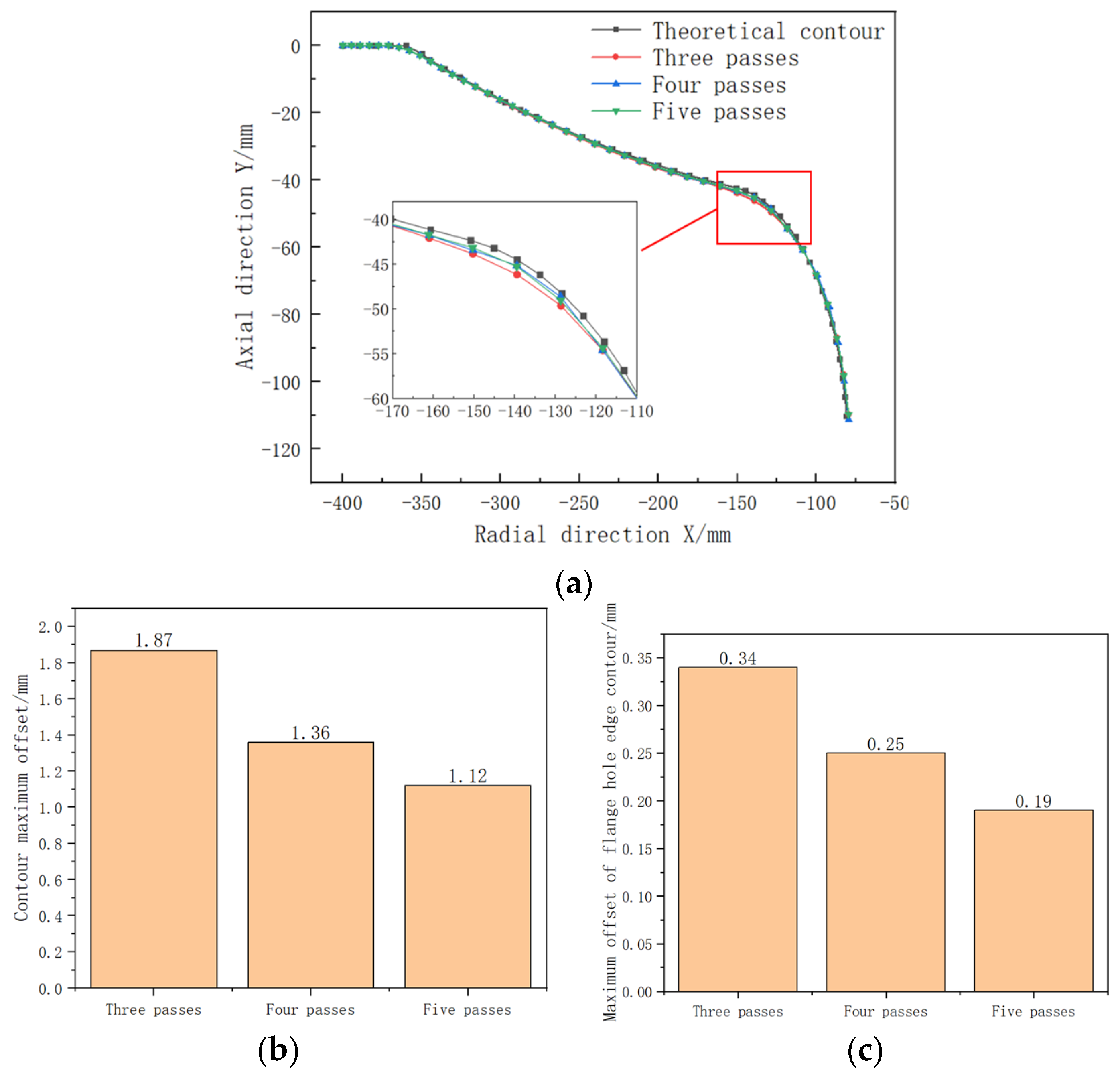
Figure 14.
Flanged hole cracking phenomenon.
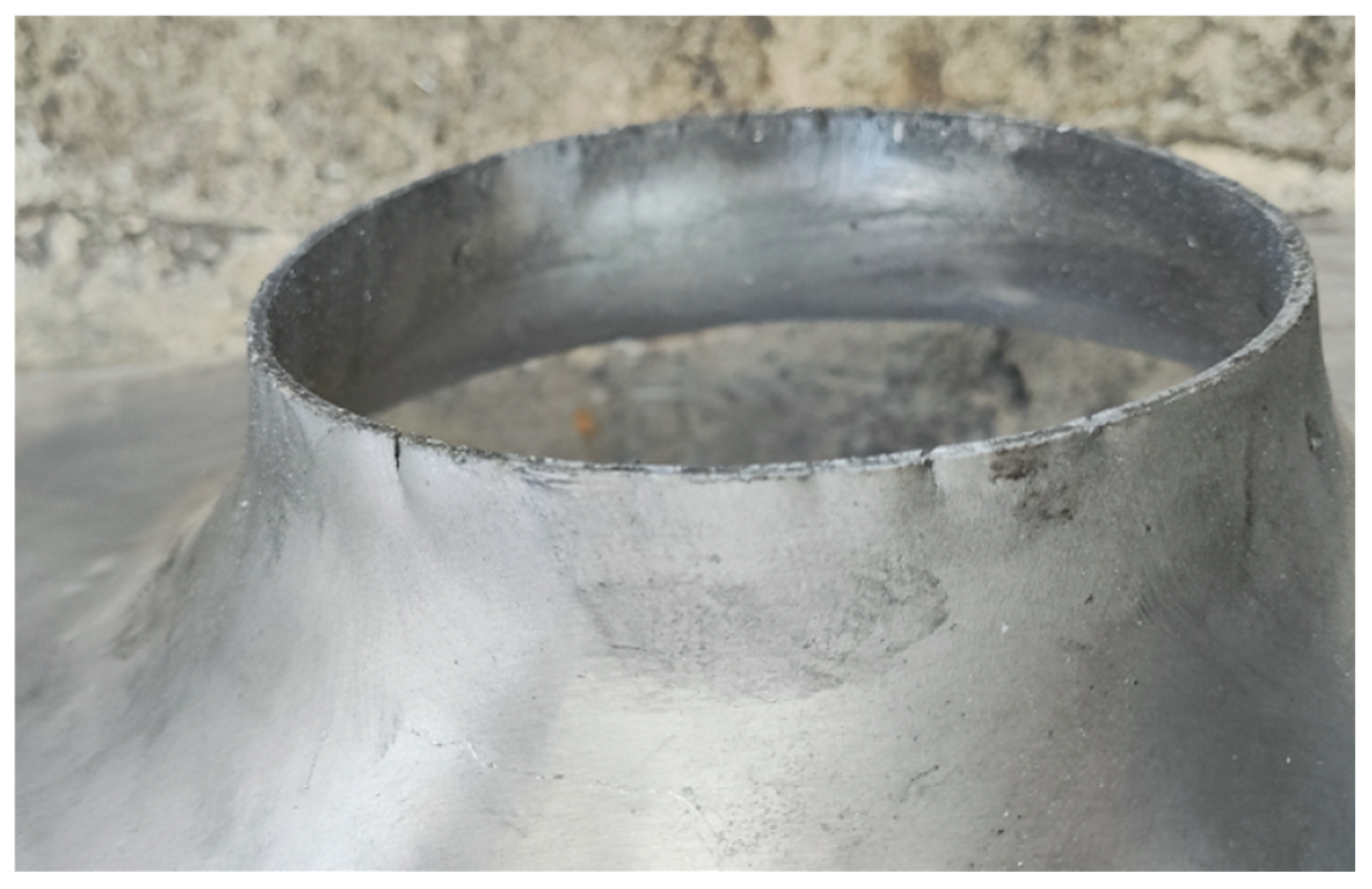
Figure 15.
Influence of feed ratio on thickness accuracies of spun parts. (a) Comparison of thicknesses of spun parts. (b) Minimum thickness value. (c) Flanged hole edge maximum thickness difference.
Figure 15.
Influence of feed ratio on thickness accuracies of spun parts. (a) Comparison of thicknesses of spun parts. (b) Minimum thickness value. (c) Flanged hole edge maximum thickness difference.

Figure 16.
Influence of feed ratio on contour accuracies of spun parts. (a) Comparison of spun part and theoretical contours. (b) Maximum contour offset. (c) Maximum offset of flanged hole edge contour.
Figure 16.
Influence of feed ratio on contour accuracies of spun parts. (a) Comparison of spun part and theoretical contours. (b) Maximum contour offset. (c) Maximum offset of flanged hole edge contour.
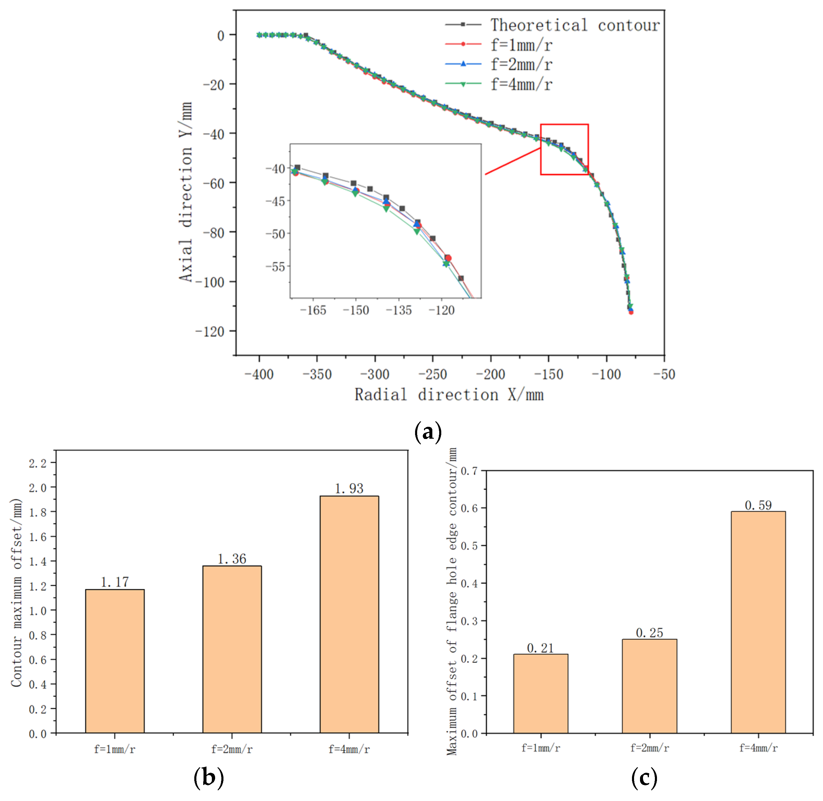
Figure 17.
Influence of roller fillet radius on thickness accuracies of spun parts. (a) Comparison of thicknesses of spun parts. (b) Minimum thickness value. (c) Flanged hole edge maximum thickness difference.
Figure 17.
Influence of roller fillet radius on thickness accuracies of spun parts. (a) Comparison of thicknesses of spun parts. (b) Minimum thickness value. (c) Flanged hole edge maximum thickness difference.

Figure 18.
Influence of roller fillet radius on contour accuracies of spun parts. (a) Comparison of spun part and theoretical contours. (b) Maximum contour offset. (c) Maximum offset of flanged hole edge contour.
Figure 18.
Influence of roller fillet radius on contour accuracies of spun parts. (a) Comparison of spun part and theoretical contours. (b) Maximum contour offset. (c) Maximum offset of flanged hole edge contour.

Figure 19.
Experimental verification of the optimized parameters.
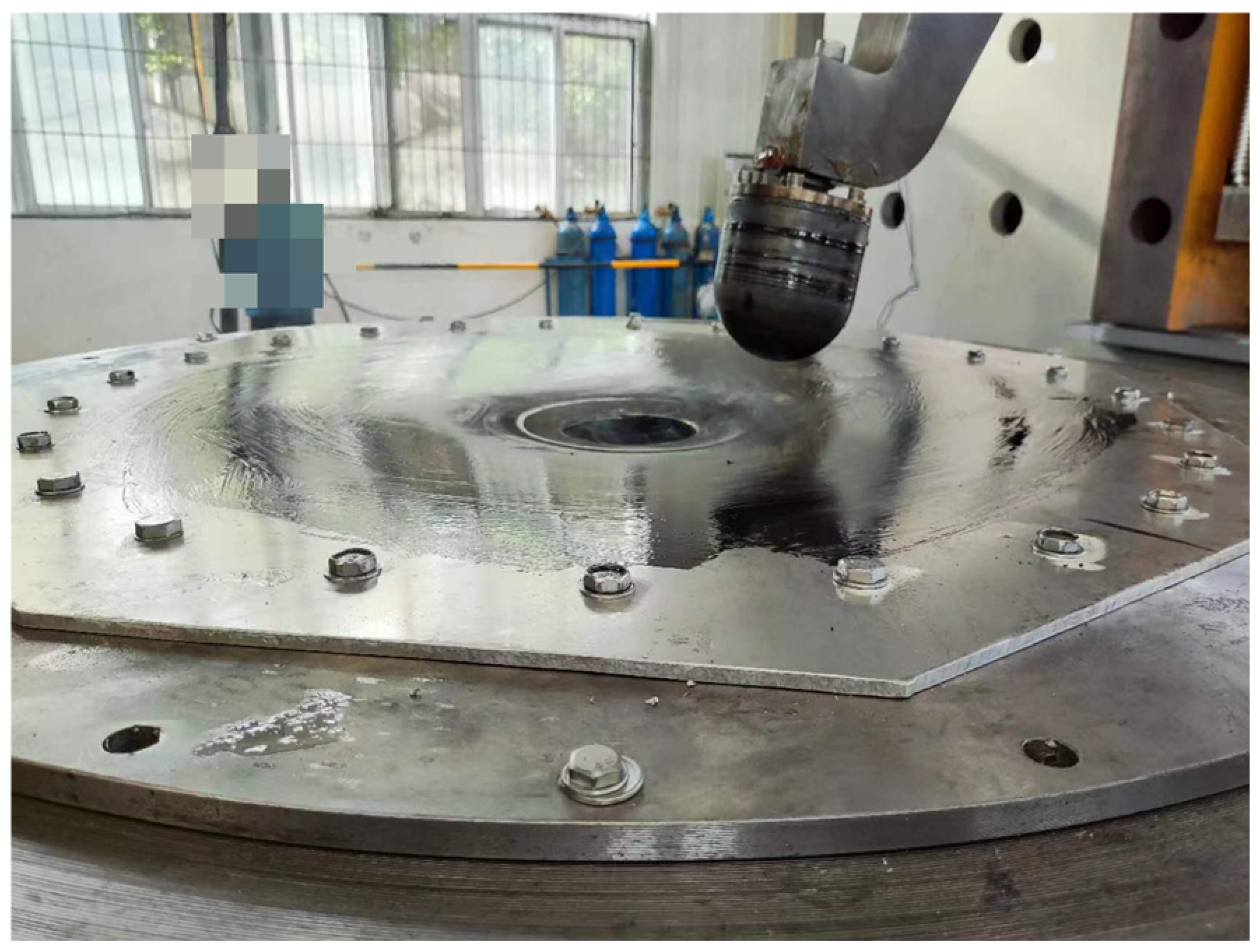
Figure 20.
Forming process of the specimen.
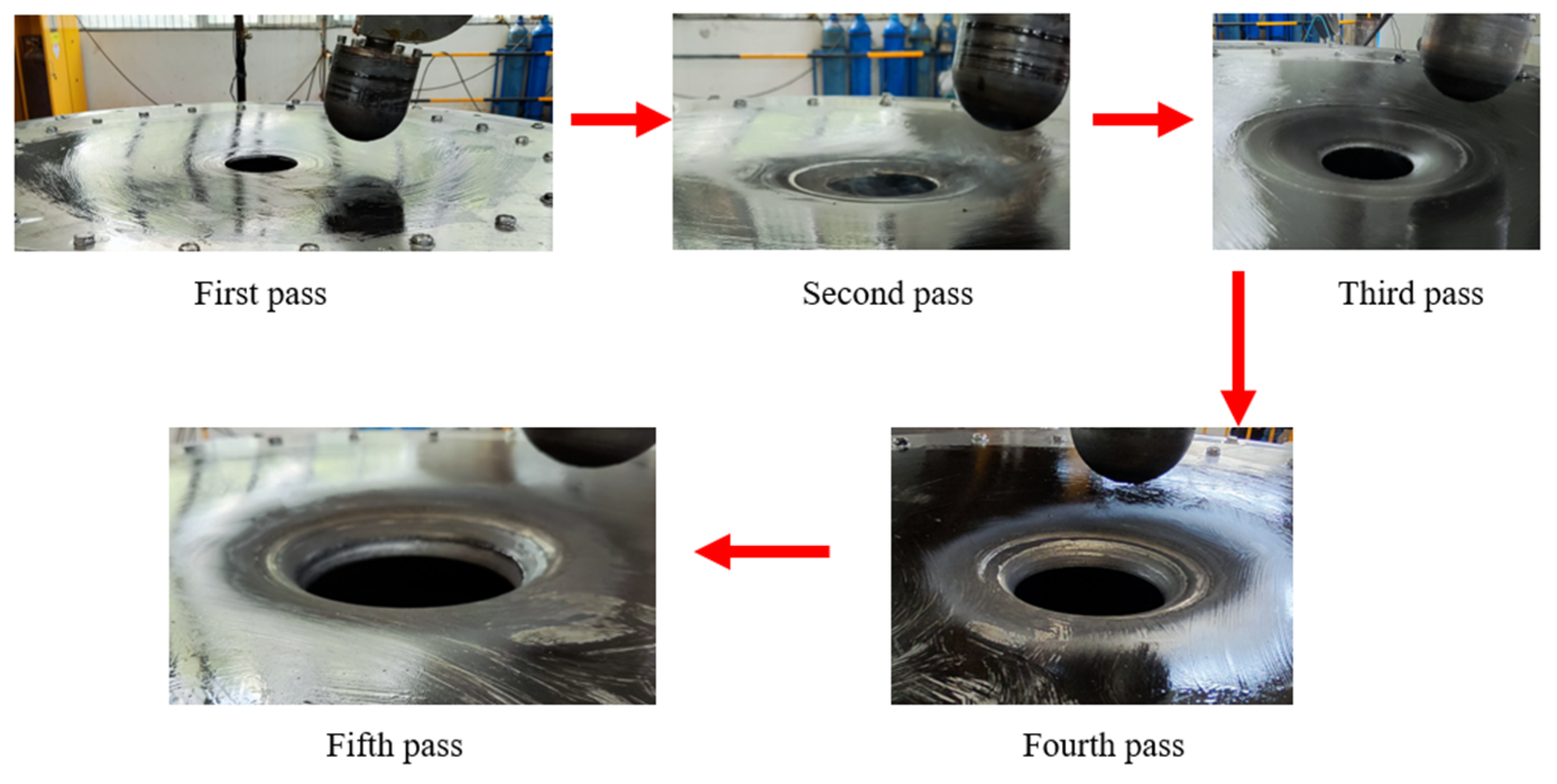
Figure 21.
Top cover with center flanged hole after spinning. (a) From the top view. (b) From the side view.
Figure 21.
Top cover with center flanged hole after spinning. (a) From the top view. (b) From the side view.

Figure 22.
The scanning results of the manufactured top cover under the optimized parameters. (a)The scanned specimen model. (b) The path for the measurement.
Figure 22.
The scanning results of the manufactured top cover under the optimized parameters. (a)The scanned specimen model. (b) The path for the measurement.

Figure 23.
Comparison of simulated and experimental thicknesses.
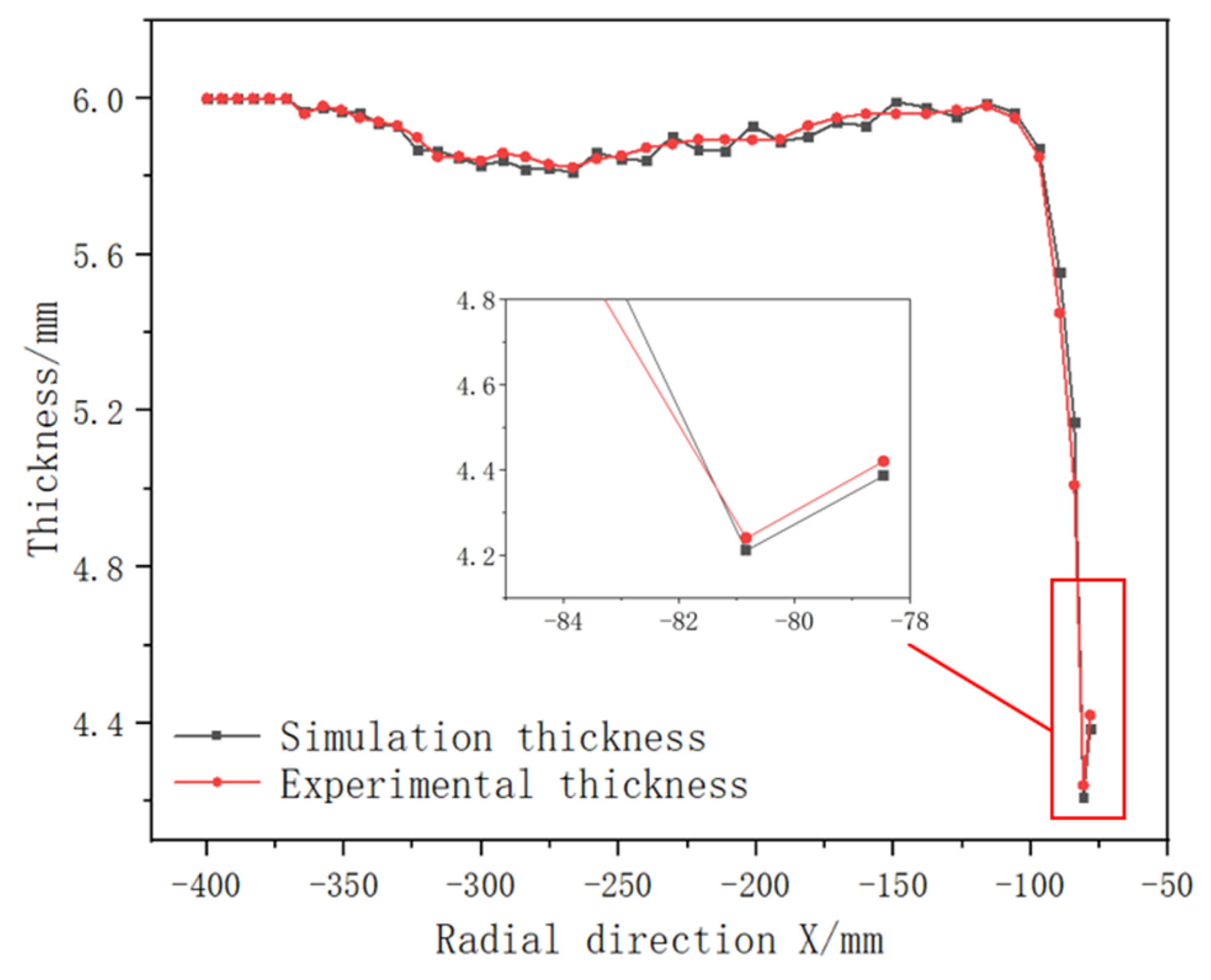
Figure 24.
Comparison of experimental, simulation, and theoretical contours.


Table 1.
Three forming strategies options.
| Option Number | Option 1 | Option 2 | Option 3 |
|---|---|---|---|
| Forming order | A→B1→B2→…→Bn | B1→B2→…→Bn→A | B1→B2→…→Bn−1→A→Bn |
Table 2.
2219-O material performance parameters.
| Elastic Modulus E/MPa | Poisson’s Ratio μ | Density ρ/(kg·m−3) | Tensile Strength /Mpa | Yield Strength /Mpa | Elongation /% |
|---|---|---|---|---|---|
| 73,100 | 0.33 | 2840 | 179 | 75.8 | 18 |
Table 3.
Trajectory parameters for preforming of flanged surface.
| Number of Passes | Trajectory Path Radius/mm | Roller Trajectory |
|---|---|---|
| Three passes | R375→R185→R140 |  |
| Four passes | R375→R261→R185→R140 |  |
| Five passes | R375→R261→R185→R151→R140 | 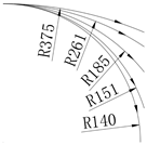 |
Disclaimer/Publisher’s Note: The statements, opinions and data contained in all publications are solely those of the individual author(s) and contributor(s) and not of MDPI and/or the editor(s). MDPI and/or the editor(s) disclaim responsibility for any injury to people or property resulting from any ideas, methods, instructions or products referred to in the content. |
© 2023 by the authors. Licensee MDPI, Basel, Switzerland. This article is an open access article distributed under the terms and conditions of the Creative Commons Attribution (CC BY) license (https://creativecommons.org/licenses/by/4.0/).
Share and Cite
MDPI and ACS Style
Zhu, L.; Huang, C.; Li, X.; Chang, X.; Yang, J. Process Parameters Optimization of One-Step Spin Forming of Top Cover with Center Flanged Hole. Metals 2023, 13, 1920. https://doi.org/10.3390/met13121920
AMA Style
Zhu L, Huang C, Li X, Chang X, Yang J. Process Parameters Optimization of One-Step Spin Forming of Top Cover with Center Flanged Hole. Metals. 2023; 13(12):1920. https://doi.org/10.3390/met13121920
Chicago/Turabian StyleZhu, Lijun, Cheng Huang, Xinhe Li, Xin Chang, and Jianyong Yang. 2023. "Process Parameters Optimization of One-Step Spin Forming of Top Cover with Center Flanged Hole" Metals 13, no. 12: 1920. https://doi.org/10.3390/met13121920
Note that from the first issue of 2016, this journal uses article numbers instead of page numbers. See further details here.