
Distribution of Rare Elements in Distillation Processing of Polymetallic Matte


Institute of Metallurgy and Ore Beneficiation JSC, Satbayev University, Almaty 050010, Kazakhstan
*
Author to whom correspondence should be addressed.
Metals 2023, 13(12), 1934; https://doi.org/10.3390/met13121934
Submission received: 27 September 2023
/
Revised: 10 November 2023
/
Accepted: 22 November 2023
/
Published: 24 November 2023
(This article belongs to the Special Issue Recovery of Rare Earth Elements from Mineral, Ores and Industrial Wastes)
Abstract
:The results of studies on the distribution of rare elements among the products of distillation processing of polymetallic mattes are present in this article. Schemes of the developed technological equipment for the implementation of the extraction processes of rare elements via the vacuum distillation of mattes are presented. Technological tests were performed with a matte of lead, copper, and antimony plants at 1100–1250 °C and a pressure of up to 700 Pa. It was established that As, Cd, Bi, In, and Ge, by more than 90% in total, are extracted into condensate and dust in the distillation process of volatile components from mattes of lead production. At the same time, antimony is distributed between the distillate residue and condensate. Antimony by 90.47%, arsenic by 78.83% and cadmium by 98.72% are distributed into sulfide condensate and dust in the distillation of copper production matte. From the matte of the antimony plant, Sb and Bi (90.76% and 89.78%, respectively) are transferred into the condensate and cyclone dust. Arsenic is distributed between the liquid and vapor phases. Based on calculations, Se and Te will be mainly concentrated in the distillation residue. High-grade copper mattes obtained in processing mattes from lead and copper plants can be further used to obtain metallic copper by converting. The condensate and dust can be processed separately or with the dust of the mainline production for rare metal extraction. Antimony matte processing condensate containing more than 70% Sb can be directed to the process of crude antimony refining.
Keywords:
matte; antimony; arsenic; cadmium; bismuth; germanium; vacuum; distillation; distillation residue; condensate; dust1. Introduction
Lead–zinc plants obtain concentrates from various deposits and, respectively, different mineralogical compositions [1]. The approximate composition of some of them is given in Table 1. In addition to the main minerals that make up the concentrate, rare metals and elements are present in small quantities.
Polymetallic mattes are obtained as an intermediate product in the pyrometallurgical processing of nominal sulfide concentrates at copper, lead, and antimony plants. Copper (Cu2S) and iron (FeS) sulfides form the basis of the polymetallic mattes of copper and lead plants. In addition to the main components, the matte contains non-ferrous metal compounds (PbS and ZnS), rare elements (cadmium, antimony, arsenic, indium, and others) in the form of sulfides, as well as selenium and tellurium, which isomorphically replace sulfur in sulfides. Moreover, the most significant amount of content in the matte after PbS and ZnS is represented by sulfides of antimony, arsenic, and cadmium.
Impurities of lead, zinc, arsenic, and antimony sulfides significantly complicate the production of high-grade copper. In this regard, various methods were and still are being developed to remove the mentioned compounds from the matte melt [2,3,4,5,6,7,8,9,10,11,12]. One of them is a distillation of volatile compounds in a vacuum at high temperatures.
The behavior and distribution of the main components of sulfides during the distillation processing of matte in a vacuum, including lead and zinc sulfides, are given and analyzed in the paper [13] and are based on great quantities of studies and technological tests. A much smaller number of publications, including [14,15,16,17,18,19,20], are dedicated to the study of the thermodynamics of chalcogenides and chalcogenide double melts of rare metals [21,22,23,24] as applied to the conditions of matte processing.
The number of technological studies, in addition to those given in [13], is limited to works [25,26,27,28]. In [25], the authors studied rare metals’ behavior on samples weighing 100 g at a temperature of 1200 °C and pressure of 65 Pa. They found that the content of antimony and bismuth did not exceed 0.1% after processing in copper matte. Arsenic removal was not observed. In study [26], the impurities were distilled at temperatures of 1100–1300 °C and a pressure of 50–130 Pa. The distillation degree after processing for 40–60 min in % was bismuth—88–98; arsenic—60–93; and antimony—40–92.
The authors of works [27] studied the formation of the phases and tested a method for the sufficient extraction of tellurium from the intermediate product of copper production (copper telluride) in the process of oxidizing roasting in a vacuum at temperatures above 1000 °C and a pressure of 0.67 kPa. Tellurium was extracted in the form of a mixture of oxides of various compositions.
The decomposition of jemsonite (Pb4FeSb6S14) at the temperature of 700 and 900 °C in a vacuum allows for the separation of up to 98% of antimony trisulfide and up to 99.5% of lead sulfide with a content of 99.17 and 98.7% of the main compound, respectively [28].
In this article, we judged the behavior of selenium, tellurium, cadmium, germanium, and indium in conditions of the vacuum distillation processing of polymetallic matte based on the construction of vapor–liquid equilibrium fields of double systems of chalcogenides of certain elements. Also, we studied the distribution of rare metals (cadmium, bismuth, and indium) and semi-metals (antimony, arsenic, and germanium) during the vacuum-thermal processing of polymetallic matte under plant conditions. The results of the research are shown below.
2. Equilibrium Distribution of Some Rare Metals under Vacuum Distillation of Mattes
When considering binary chalcogenide systems of iron, lead, and antimony, the minimum pressure value is 700 Pa. This is because it is not possible to reduce the pressure over chalcogenide melts under technological conditions due to the magnitude of the saturated vapor pressure of some compounds. In addition, when calculating the boundaries of the coexistence of liquid and vapor fields (L + V), the boiling point of the liquid was taken to be the temperature at which the sum of the partial pressures of each of the compounds of the binary system is equal to atmospheric (101.33 kPa) or 700 Pa. The concentration of compounds in the vapor phase was found to be a part of the partial pressure of chalcogenides in the total pressure of chalcogenides over the melt.
The chalcogenide distribution based on phase diagrams was determined as follows. For a chalcogenide alloy of a certain composition (on the x-axis), the boiling point was determined (the intersection of the ordinate corresponding to the composition with the boiling line curve). Each boiling point corresponds to the composition of the vapor phase—the upper line of the vapor–liquid equilibrium field (the line parallel to the x-axis from the boiling point to the vapor composition line). This vapor composition corresponds to the composition of the condensate, based on which judgments were made about the distribution of elements between the condensed phase—melt—distillation residue and condensate.
The major amount of selenium and tellurium isomorphically replaces sulfur in copper and iron chalcogenides—the basis of industrial mattes.
The equilibrium distribution of selenium and tellurium upon distillation from copper chalcogenide alloys was studied by us earlier [29]. During the distillation of volatiles at low pressure, as a rule, at temperatures of 1100–1250 °C, the dissociation pressure of low-volatile pure copper sulfide will range from 0.5 to 7 Pa, copper selenide from 28 to 230 Pa, and copper telluride from 1.5 to 9 Pa. Consequently, copper sulfide and telluride completely, and copper selenide—mainly, will be concentrated in the distillation residue.
2.1. Iron Chalcogenides
When constructing state diagrams with vapor–liquid equilibrium fields in systems of iron chalcogenides, the vapor pressure of iron sulfide is assumed to be equal to the partial pressure of chalcogen vapor over sulfide [30], over liquid selenide [31] and over telluride [32].
Studies devoted to determining the activity of components in binary molten systems of iron chalcogenides have not been found. Assuming that the systems obey, as is the case in most cases, the law of ideal solutions and the boundaries of the coexistence fields of liquid solutions and vapor are calculated for atmospheric pressure and pressures of 15 and 0.7 kPa (Figure 1).
Due to the absence of phase diagrams for the condensed phases of binary systems, the liquidus line (dashed line between the melting points of individual chalcogenides) is drawn conditionally.
Here, as well as in the case of copper chalcogenides, the components of the vapor will be sulfur, selenium, and tellurium, formed as a result of the thermal dissociation of compounds. The composition of the vapor phase for non-volatile chalcogenides is conditionally indicated as the corresponding compound mole fractions.
As can be seen from Figure 1, sulfide, selenide, and telluride of iron at a pressure of 0.7 kPa under equilibrium conditions can be completely decomposed into iron and the corresponding chalcogen: FeS at temperatures above 1884 °C, FeSe at temperatures above 1556 °C, and FeTe at temperatures above 906 °C.
When considering the position of the boundaries of the melt–vapor phase transitions, it can be seen that a decrease in pressure over the liquid bath has practically no effect on the quality of the chalcogens separation. Based on the state diagrams, the decomposition degree increases from sulfur to tellurium. Separation via the distillation of sulfur and selenium in one stage at a process pressure of 0.7–15 kPa is impossible. In the FeS—FeTe and FeSe—FeTe systems, the vapor phase is represented mainly by tellurium dimers.
In the distillation process of volatiles carried out, as a rule, at temperatures of 1100–1250 °C and low pressure of 0.7–15 kPa, sulfide and selenide of iron will be completely accumulated in the distillation residue. Iron telluride, based on dissociation pressure values of the compound at 700 Pa, will preferentially decompose into elements before reaching the melting point of double systems.
2.2. Lead Chalcogenides
Thermodynamic studies of double lead chalcogenide systems were carried out by the authors of several works [33,34,35]. In the study [33], based on thermal analysis and the study of the structure of cast and annealed alloys, a phase diagram of the PbSe—PbTe system was constructed, where the compounds form a continuous series of solid solutions with a minimum at the liquidus line. The author of [34] constructed a “temperature–composition” diagram for the condensed phases of the PbS—PbSe system with a liquidus line similar to the previous system and the presence of solid solutions in the entire concentration range.
In the study [35], based on the saturated vapor pressure of lead telluride, the activities and thermodynamic functions of the components were determined at 950 K. A slight deviation of the binary chalcogenide system from the ideal state was established. The latter allowed us to consider the system, like the other two, at temperatures of distillation separation of mattes ideal.
Phase transitions for binary molten lead chalcogenide systems are calculated according to Raoult’s law. The coexistence fields of the melt and vapor, corresponding to the conduct of distillation processes at atmospheric and low pressures, are plotted on the state diagrams of condensed phases [35] and are shown in Figure 2.
At atmospheric pressure, lead sulfide, selenide, and telluride can be transferred to the vapor phase at temperatures above 1243 °C (PbS), 1262 °C (PbSe), and 1323 °C (PbTe). A pressure decrease to 15 kPa in the PbS—PbSe system is accompanied by a shift in the “condensed phase—vapor” coexistence field to the S + L field (Figure 3b) and divides it into three regions: L + V, S + L + V, and S + L. In the PbS—PbTe system, the L + V field at 15 kPa is located above the liquidus line. When the pressure drops to 0.7 kPa, the equilibrium field “condensed phase—vapor” is superimposed on the solid solutions field. Moreover, the coexistence fields of liquid and solid phases are partially located in the liquid solutions area. In the PbSe—PbTe system, the L+V field at 15 kPa is also located above the liquidus line. When the pressure drops to 0.7 kPa, the equilibrium field “condensed phase—vapor” is superimposed on the field of solid solutions (S), and the coexistence fields of liquid and solid phases are partially located in the area of liquid solutions.
When considering the position of the phase transition boundaries with the participation of the vapor phase, it can be seen that a decrease in pressure over the liquid bath impairs the chalcogens separation since the width of the coexistence fields of liquid and vapor decreases with temperature. Therefore, the separation of chalcogenides in one stage by thermal vacuum treatment is impossible. In the distillation of volatiles at low pressure and temperatures of 1100–1250 °C, lead chalcogenides will concentrate in the vapor phase.
2.3. Antimony Chalcogenides
Based on the position of the fields, boundaries of the liquid and vapor phases coexist in the systems Sb2S3—Sb2Se3, Sb2Se3—Sb2Te3, and Sb2S3—Sb2Te3; it can be concluded that it is impossible to separate binary chalcogenide systems into separate compounds in the process of one cycle “evaporation—condensation”. Different effects of pressure reduction over melts are noted. In the Sb2S3—Sb2Se3 system, a decrease in pressure from atmospheric to 0.7 kPa does not change the position of the liquid and vapor field boundaries (L + V) in temperature. In the Sb2S3—Sb2Te3 system, the field width (L + V) decreases with decreasing pressure. In the Sb2Se3—Sb2Te3 system, the field width concerning temperature decreases first and then increases. The reason for such a change in the position of the boundaries of the fields (L + V) in the last two systems is, apparently, inaccuracies in determining the vapor pressure of the initial antimony chalcogenides.
At the same time, the position of the boiling curves of antimony chalcogenide solutions indicates the complete transfer of compounds into the vapor phase under the conditions of the distillation processing of mattes (at temperatures of 1100–1250 °C), even at atmospheric pressure.
2.4. Dual Systems of Antimony Trisulfide with Copper, Iron, and Lead Sulfides
We most comprehensively studied dual systems of antimony with chalcogens and antimony trisulfide with the main components of polymetallic matte of lead plants: copper, iron, and lead sulfides [13]. Figure 3 shows a complete state diagram of these systems where the boundaries of vapor–liquid equilibrium fields (L + V) at atmospheric pressure and in vacuum at 700 Pa are plotted (shaded).
The shape of the boundaries of the region of Cu2S—Sb2S3 liquid solutions and the vapor phase coexistence imply the almost complete separation of the system into its components. Thus, 98.39 mol. % of the vapor phase is represented by antimony sulfide vapor at 1 mol. % (2.11 wt. %) of Sb2S3 in the condensed phase. The content of copper sulfide in the vapor is 0.76 wt. %. Reducing the pressure improves the completeness of separation: the concentration of Cu2S in the vapor is 0.30 mol. % (0.14 wt. %) at 700 Pa at the above-mentioned content of antimony sulfide in the matte. Thus, a practically complete release of antimony sulfide to condensate during vacuum distillation should be expected.
In the FeS—Sb2S3 system, due to the lack of a condensed phase diagram, the solution boiling point at low pressure was calculated to be the concentration of 40 mol. % (72.04 wt. %) Sb2S3 in the alloy. The composition of the vapor phase was calculated for solutions with a boiling point higher than the melting point of iron sulfide. Along with our calculations, the boundaries of the vapor–liquid equilibrium fields are shown in Figure 3, which were calculated based on thermodynamic data [22] found by the calorimetric method. As can be seen, the boundaries of the (L + V) fields coincide except for the region of Sb2S3-poor solutions at atmospheric pressure.
The position of the boundaries of the field of liquid solutions and the vapor phase coexistence in the vacuum allows us to predict the possibility of almost complete separation of liquid solutions into their constituent sulfides. Possible difficulties can arise in the case of lowering the solution’s boiling point below the liquidus temperature, which can be eliminated by increasing the technological pressure.
The field of liquid and vapor phases’ coexistence in the system of PbS—Sb2S3 at atmospheric pressure is practically degenerate, which indicates the impossibility of distillation separation of the melt into constituent sulfides. A decrease in pressure slightly increases the field width (L + V 700 Pa) by temperature. However, significant enrichment of the vapor phase with antimony sulfide is only possible for Sb2S3 alloys of the state diagram edge that does not correspond to the real compositions of matte.
Based on the values of saturation vapor pressure and dissociation, it is assumed that zinc and cadmium chalcogenides will be transferred to the vapor phase in a completely dissociated form, and bismuth, indium, and arsenic will be transferred in the form of their compounds with chalcogens.
By analyzing the results of the cited studies, it should be noted that data on the distribution of other rare elements, with a few exceptions, in the practice of vacuum-thermal distillation processing of polymetallic matte, are not available to date.
In this regard, the distribution of rare metals (cadmium, bismuth, and indium) and semi-metals (antimony, arsenic, and germanium) during vacuum-thermal processing of polymetallic matte under plant conditions was studied. The results of the study are presented in this article and described below.
3. Distribution of Rare and Semi-Metals during Vacuum-Thermal Processing
3.1. Materials
As a research object, we chose the next polymetallic mattes:
- Mattes from the settling tanks of shaft furnaces from the lead production, which are sent to reflective smelting to reduce the content of lead;
- Mattes from reduction shaft smelting of intermediate products and waste of the lead plant;
- Reflection smelting matte of the copper smelter;
- Electromelting matte of antimony smelter.
The approximate average content of base metals and rare elements in matte is given in Table 2.
Polymetallic mattes of lead and copper production in crystalline state are represented by sulfides, arsenides, and antimonides of copper, iron, lead, and zinc. Chalcosine is represented by isometric grains up to 100 microns in size. Rarely is chalcosine with fine inclusions of galena found. Galenite is present in a significant amount (12–15%). Metallic lead (7–10%) is found as separate grains and rounded inclusions. Single grains of Cu2Sb, pyrite, and metallic copper are observed. Speiss is present in mattes and consists of arsenides and antimonides, which include lead of the approximate composition Cu12(As,Sb,Pb)4. Cadmium is represented by sulfide. Selenium and tellurium in matte are isomorphically substituted by sulfur in the compounds and are not detected as separate phases. Bismuth, indium, and germanium compounds were not detected due to the lower sensitivity threshold of the instruments and local distribution in the matte.
Metallic antimony, antimony trisulphide (Sb2S3), sodium sulfide, magnetite, tetrahedrite, pyrrhotite, and hematite were found in the antimony matte.
3.2. Technological Equipment for Distillation Processing of Polymetallic Matte
A unit (capacity of up to 15 tons per day) was developed as a result of conducting a large volume of technological tests in lead plant conditions and improving the distillation process of polymetallic matte separation. The scheme of this unit is shown in Figure 4.
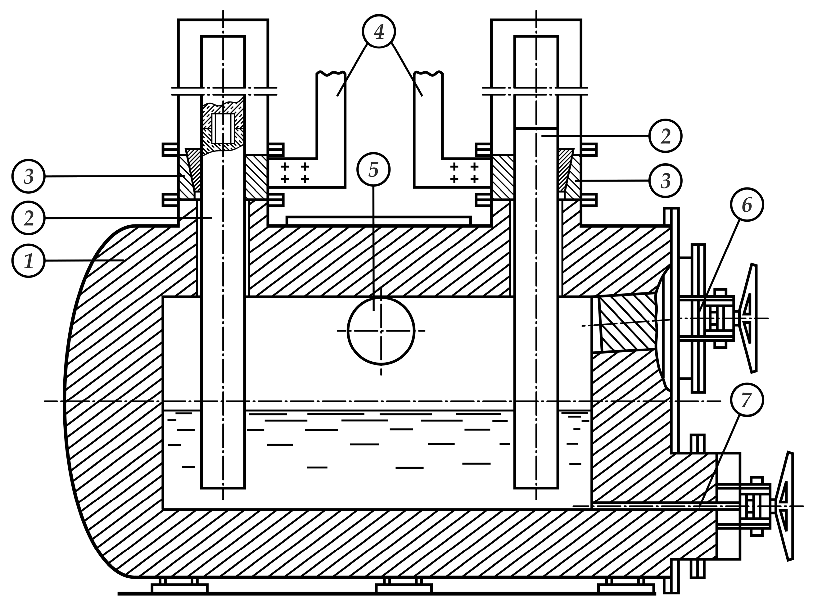
The unit for the distillation processing of matte included a vacuum electric furnace (Figure 5) via matte as a resistance body during heating. The depth of the bath at the beginning of the process was 0.37 m; the evaporation area was 2 m2; and the tonnage of the furnace by matte was 3.75 t.
The electric furnace was equipped with a loaded hatch for priming liquid matte and a discharge hatch for a drain of the treated matte. The water-cooled cyclone-type condenser is connected to the furnace space by a heated vapor line made in the form of a graphite tube. From below, the condenser is equipped with a hopper to collect the self-crumbling finely dispersed condensate, which is mounted on a cart for quick replacement with an empty hopper. In the central cooled tube of the condenser, a bag filter is installed to catch fine dust. Cyclone dust collectors with bag filter for gas flow cleaning from finely dispersed condensate particles and oil filters for fine gas flow cleaning are installed between the condenser and gas evacuation system.
Condensate hopper changing, priming of matte, and discharge of treated matte into the molds were performed when the vacuum unit was filled with nitrogen from the gas pipeline. The removal of a hopper with condensate, the installation of an empty hopper, and sealing with the condenser body were performed using a simple vertical displacement mechanism operated by a hydraulic jack (Xilin Brand, Ningbo Ruyi Joint Stock Co., Ltd., Metropolis of Hangzhou, Zhejiang Province, China), with the operation time of 3–5 min.
Due to the possibility of spontaneous ignition, the finely dispersed sulfide condensate in the removed hopper was moistened with water. Then, the contents were sent to the mixing place.
The residue after vacuum distillation is a copper matte with low lead and zinc content. It was poured into molds, was crashed, and then sent for conversion (to another plant).
3.3. Operating Procedure
The distillation process of polymetallic matte included the following operations: the pouring of liquid matte at atmospheric nitrogen pressure, the sealing of the priming hatch, gases evacuation from the furnace space, the supply of electric power to electrodes, the heating and distillation of volatile components from the loaded matte, filling the plant with nitrogen, the opening of the blast-hole, and the draining of the treated matte into casting forms. After removing the treated matte from the furnace space, the loading hatch was opened, and the next portion of the liquid matte was poured through a removable tray installed by a crane in the loading hatch. Simultaneously with the filling of the matte, the condensate hopper was replaced by an empty container. The process was repeated after sealing the hatch and the blast-hole and changing the hoppers.
When processing copper and antimony production matte, the electric furnace bath was filled by melting lumpy material loaded through the loading hatch. When loading a lumpy copper matte supplied by another plant, the melt of the lead smelting matte from the lead plant was used as a heater.
Antimony matte was distilled in a vacuum electric furnace with a capacity of the matte up to 0.4 t. The vacuum electric furnace design is similar to that shown in Figure 5. The antimony matte has a big hygroscopicity and was stored for a long time. Therefore, the antimony matte before vacuum distillation processing was subjected to smelting for slag separation.
The technological process of the distillation of volatile components from polymetallic matte was performed at 1100–1250 °C. Rapid gas evolution and melt splashing at the initial stage of the technological process (starting from pressure 27–40 kPa) is common, irrespective of the processed material. Therefore, the process was conducted with a gradual decrease in pressure from this pressure to 0.6–1.2 kPa. The reason for this, in our opinion, (besides the rapid evaporation of volatile components of matte) could be the reaction of the interaction between sulfides and oxides with the evolution of the gas phase.
During factory tests, more than 500 tons of matte were processed. One hundred tons of sulfide condensate was obtained. The electric power consumption was 400–500 kWh to one-ton matte. The current density, which provides the temperature regime of the distillation process, was 1000 kA/m2 of sulfide melt. The voltage drop is about 10 V × m−1.
Difficulties accompanying the technological process consisted of synchronization of liquid shaft melting matte feeding into the vacuum electric furnace and loading operation duration due to the small capacity of ladles for liquid matte transfer for processing, as well as corresponding crane equipment lifting capacity. The aggressiveness of sodium-containing melt about the lining should be noted in the processing of antimony production matte.
3.4. Technological Test Results for Matte Processing
The content of elements was determined after selecting a representative sample and averaging it. Antimony, arsenic, and cadmium in the initial material and products were determined using a chemical method, bismuth, indium, and germanium via a quantitative spectral method. The element distribution among processed products was calculated based on the mass amount of the element in each product relative to its content in the source material.
Testing of vacuum technology of polymetallic matte processing showed that nonferrous metals such as lead and zinc are more than 95–96% transferred to sulfide condensate. Consequently, copper and iron chalcogenides and selenium and tellurium are concentrated in the distillation residue almost completely.
The typical distribution of rare metals and nonmetals present in the initial matte on processing products is given below (Table 3, Table 4, Table 5 and Table 6).
Arsenic, cadmium, bismuth, indium, and germanium are extracted into condensate and cyclone dust more than 90% in total as a result of vacuum distillation of matte of reflection and reduction smelting (Table 3 and Table 4). Antimony is distributed between the distillation residue and sulfide condensate in comparable quantities. The speiss phase formation is a cause of it. So, layers of matte and speiss, which could be separated by the mechanical method, were observed at the pouring of distillate matte—a residue from distillation processing of matte from the reduction smelting of lead production in the cellular molds after crystallization.
During copper matte processing (collectively with a 31.5% reduction matte), antimony by 90.47%, arsenic by 78.83%, and cadmium by 98.72% are extracted into sulfide powder condensate and dust (Table 5).
Antimony and bismuth from antimony matte predominantly (90.76% and 89.78%, respectively) transfer into the condensate and cyclone dust as a consequence of sulfide evaporation. Arsenic is distributed in comparable amounts between the liquid and vapor phases.
It is advisable to send condensate containing rare elements, the bulk of which are lead and zinc chalcogenides, to the stockyard and process according to the main technological production scheme. Rare metals will be transferred to the dust of the main workshops and processed according to the hydrometallurgical scheme. The condensate from the processing of antimony matte can be used in the bismuth removal operation in the technological scheme for refining crude lead.
As a result of the vacuum-thermal processing of polymetallic matte, along with the extraction of rare elements, a high-grade copper matte is obtained, which is suitable for producing high-grade blister copper and then electrolysis metal with a content of more than 99.99 wt. % Cu.
4. Conclusions
Based on the data obtained during research on the behavior of rare metals during the distillation processing of polymetallic mattes, the following conclusions can be drawn. Selenium and tellurium during the vacuum distillation of matte are concentrated as copper and iron selenides and tellurides in the distillation residue from matte distillation. Cadmium, bismuth, indium, and germanium are transferred in sulfide condensate and cyclone dust. Antimony and arsenic in lead and antimony matte may be distributed in comparable quantities between the melt and condensate due to the formation of speiss and partial evaporation of sulfides.
High-grade copper matte for obtaining metallic copper via converting was obtained as a result of matte processing from lead and copper plants. Condensate and cyclone dust may be processed separately or together with the dust of the primary production to extract rare metals. The condensate from antimony matte processing that contains more than 70% antimony can be rationally used for crude antimony refining from iron and arsenic.
It should be noted that the developed technology possesses universality. It can be used for the recovery of volatile components from sulfide melts of different compositions and different productions.
Author Contributions
Conceptualization, V.V.; methodology, V.V.; investigation, X.L. and S.T.; data curation, A.N. and V.V.; writing—original draft preparation, A.N. and V.V.; writing—review and editing, A.N. and S.T.; visualization, A.N. and X.L.; project administration, V.V. All authors have read and agreed to the published version of the manuscript.
Funding
This research was funded by the Ministry of Science and Higher Education of the Republic of Kazakhstan, grant number AP14869944.
Data Availability Statement
The data presented in this study are available in the article.
Conflicts of Interest
The authors declare no conflict of interest.
References
- Issakova, R.A.; Nesterov, V.N.; Chelokhsaev, L.S. Fundamentals of Polymetallic Raw Materials Vacuum Pyro-Selection; Nauka: Alma-Ata, Kazakhstan, 1976; 255p. [Google Scholar]
- Neustroev, V.I.; Karimov, K.A.; Naboichenko, S.S.; Kovyazin, A.A. Autoclave leaching of arsenic from copper concentrate and matte. Metallurgist 2015, 59, 177–179. [Google Scholar] [CrossRef]
- Dosmukhamedov, N.; Zholdasbay, E. The solubility of Cu, Pb, As, Sb of copper-lead matte in the slag. Kompleks. Ispolz. Miner. Syra Complex Use Miner. Resour. 2020, 312, 31–40. [Google Scholar] [CrossRef]
- Argyn, A.; Zoldasbay, E.; Dosmukhamedov, N. Improving the quality of converting products by the joint smelting of high-sulfur copper concentrate with copper-lead matte. Kompleks. Ispolz. Miner. Syra Complex Use Miner. Resour. 2023, 328, 50–58. [Google Scholar] [CrossRef]
- Dyussebekova, M.A.; Kenzhaliyev, B.K.; Kvyatkovskiy, S.A.; Sit’ko, E.A.; Nurkhadianto, D. The main reasons for increased copper losses with slags from vanyukov furnace. Metallugija 2021, 60, 309–312. [Google Scholar]
- Wright, S.; Sun, S.Y.; Jahanshahi, S. Rate of removal of lead from copper matte by submerged gas injection. Miner. Process. Extr. Metall. 2023, 13, 99–109. [Google Scholar] [CrossRef]
- Kenzhaliyev, B.K.; Kvyatkovskiy, S.A.; Dyussebekova, M.A.; Semenova, A.S.; Nurhadiyanto, D. Analysis of existing technologies for depletion of dump slags of autogenous melting. Kompleks. Ispolz. Mineral. Syra Comp. Use Min. Res. 2022, 323, 23–29. [Google Scholar] [CrossRef]
- Minic, D.; Strbac, N.; Mihajlovic, I.; Zivkovic, Z. Thermal analysis and kinetics of the copper-lead matte roasting process. J. Therm. Anal. Calorim. 2005, 82, 383–388. [Google Scholar] [CrossRef]
- Sineva, S.; Shevchenko, M.; Shishin, D.; Hidayat, T.; Chen, J.; Hayes, P.C.; Jak, E. Phase equilibria and minor element distributions in complex copper/slag/matte systems. JOM 2020, 72, 3401–3409. [Google Scholar] [CrossRef]
- Volodin, V.N.; Trebukhov, S.A.; Kenzhaliyev, B.K.; Nitsenko, A.V.; Burabaeva, N.M. Melt–Vapor Phase Diagram of the Te–S System. Rus. J. Phys. Chem. A 2018, 92, 407–410. [Google Scholar] [CrossRef]
- Sohn, H.S.; Fukunaka, Y.; Oishi, T.; Sohn, H.Y.; Asaki, Z. Kinetics of As, Sb, Bi and Pb volatilization from industrial copper matte during Ar+O2 bubbling. Metall. Mater. Trans. B 2004, 35, 651–661. [Google Scholar] [CrossRef]
- Dosmukhamedov, N.K.; Zholdasbay, E.E.; Argyn, A.A.; Kurmanseitov, M.B. Behavior of Zn, Pb, As compounds during copper-zinc concentrate and matte melting in converters. Non-Ferr. Metal. 2020, 49, 11–18. [Google Scholar] [CrossRef]
- Volodin, V.N.; Issakova, R.A. Distillation Separation Processes of Sulfide and Metallic Melts: Theory and Technology; Tengri Ltd.: Karaganda, Kazakhstan, 2015; 260p. [Google Scholar]
- Maekawa, T.; Yokokawa, T.; Niwa, K. Enthalpies of mixing in the liquid state IV. Bi + Se and Sb + Se. J. Chem. Thermodyn. 1972, 4, 873–878. [Google Scholar] [CrossRef]
- Predel, B.; Piehl, J.; Pool, M.J. BeitragzurKenntnis der thermodynamischenEigenschaftenflüssiger Thallium-Selen-, Wismut-Selen- und Antimon- Selen-Legierungen. Int. J. Mater. Res. 1975, 66, 388–395. [Google Scholar] [CrossRef]
- Predel, B.; Gerdes, F.; Gerling, U. Berücksichtigung der Assoziation in der Dampfphase bei Aktivitätbestimmungen und Revision der Aktivitäten flüssiger Legierungen der Systeme Selen-Thallium, Selen-Wismut und Selen-Antimon. Int. J. Mater. Res. 1979, 70, 109–112. [Google Scholar] [CrossRef]
- Sullivan, C.L.; Prusaczyk, L.E.; Carlson, K.D. Molecules in the equilibrium vaporization of antimony sulfide and selenide. J. Chem. Phys. 1970, 53, 1289–1290. [Google Scholar] [CrossRef]
- Bagdavadze, J.; Chagelishvili, R.; Gagnidze, N.; Kandelaki, A.; Rasmadze, R.; Tsikaridze, Z. Study of high-temperature process for obtaining antimony sulfide and metallic Sb. Bull. Georg. Natl. Acad. Sci. 2013, 7, 75–79. [Google Scholar]
- Shi, C.; Li, N.; Zhang, W. Thermodynamic assessment of the Sb–S and In–S binary systems. Intern. J. Mater. Res. 2021, 112, 373–381. [Google Scholar] [CrossRef]
- Aliev, F.R.; Orujlu, E.N.; Babanly, D.M. Thermodynamic properties of the Sb2Te3 compound. Azerb. Chem. J. 2021, 4, 53–59. [Google Scholar] [CrossRef]
- Ilyasheva, N.A. Study of Cu2S–Sb2S3 system at 320–400 °C. Inorg. Mater. 1973, 9, 1677–1679. [Google Scholar]
- Ibragimov, Y.T.; Shendyapin, A.S.; Nesterov, V.N.; Khobdabergenov, R.Z. Vapor pressure in the Sb2S3–Cu2S system. Proc. Inst. Metall. Ore Benef. Acad. Sci. KazSSR 1977, 52, 61–65. [Google Scholar]
- Lee, Y.H.; Itagaki, K. Thermodynamic study of liquid Sb–S and Sb2S3–FeS systems by the use of a drop-calorimeter. Trans. Jpn. Inst. Met. 1986, 27, 987–995. [Google Scholar] [CrossRef]
- Dong, Z.; Li, L.; Xiong, H.; Liu, G.; Wang, Y.; Zhou, Z.; Xu, B.; Yang, B. Application of modified molecular interaction volume model for phase equilibrium of PbS–Sb2S3 system in vacuum distillation. Vacuum 2022, 20, 111067. [Google Scholar] [CrossRef]
- Rametani, H.; Yamauchi, C.; Murao, K.; Hayashida, M. A fundamental study on the vacuum treatment of molten matte and white metal. Trans. Jpn. Inst. Met. 1973, 14, 218–223. [Google Scholar] [CrossRef]
- Allaire, A.; Harris, R. Vacuum distillation of copper matte to remove lead, arsenic, bismuth, and antimony. Metall. Mater. Trans. B 1989, 20, 793–804. [Google Scholar] [CrossRef]
- Nitsenko, A.; Linnik, X.; Volodin, V.; Tuleutay, F.; Burabaeva, N.; Trebukhov, S.; Ruzakhunova, G. Phase transformation and tellurium recovery from technical copper telluride by oxidative-distillate roasting at 0.67 kPa. Metals 2022, 12, 1774. [Google Scholar] [CrossRef]
- Zhou, Z.; Liu, D.; Xiong, H.; Wang, C.; Ma, B.; Wei, L.; Chen, Y.; Huang, K. A vacuum distillation process for separation of antimony trisulfide and lead sulfide from jamesinite. Vacuum 2021, 188, 110172. [Google Scholar] [CrossRef]
- Nitsenko, A.; Volodin, V.; Linnik, X.; Burabaeva, N.; Tuleutai, F. Behavior of copper chalcogenides during vacuum-thermal processing. Metalurgija 2023, 62, 125–128. [Google Scholar]
- Richardson, F.D.; Jeffes, H.E. The thermodynamics of substances of interest in iron and steel making. J. Iron Steel Inst. 1952, 171, 165–168. [Google Scholar]
- Placente, V.; Scardala, P.; Fontana, D. Decomposition pressure and standard enthalpies of sublimation and formation of iron monoselenide. J. Alloys Compd. 1992, 189, 263–267. [Google Scholar] [CrossRef]
- Ipser, H.; Komarek, K.L. Thermodynamic properties of iron-tellurium alloys. Monatshefte Für Chem./Chem. Mon. 1974, 105, 1344–1361. [Google Scholar] [CrossRef]
- Yelagina, Y.I.; Abricosov, N.K. Study of the PbTe–PbSe system. Rep. Acad. Sci. USSR 1956, 111, 353–354. [Google Scholar]
- Simpson, D.R. The binary System PbS–PbSe. Econ. Geol. 1964, 59, 150–153. [Google Scholar] [CrossRef]
- Sokolov, V.V.; Dolgikh, V.A.; Pashinkin, A.S.; Novoselova, A.V. Saturated steam pressure in the PbTe–PbSe system. Inorg. Mat. 1969, 5, 279–282. [Google Scholar]
Figure 1.
Vapor–liquid equilibrium fields in binary iron chalcogenide systems: (a) FeS—FeSe; (b) FeS—FeTe; (c) FeSe—FeTe.
Figure 1.
Vapor–liquid equilibrium fields in binary iron chalcogenide systems: (a) FeS—FeSe; (b) FeS—FeTe; (c) FeSe—FeTe.

Figure 2.
The state diagrams of lead chalcogenides: (a) PbS—PbSe in the temperature range from 800 to 1400 °C; (b) PbS—PbSe in the temperature range from 1060 to 1120 °C; (c) PbS—PbTe; (d) PbSe—PbTe.
Figure 2.
The state diagrams of lead chalcogenides: (a) PbS—PbSe in the temperature range from 800 to 1400 °C; (b) PbS—PbSe in the temperature range from 1060 to 1120 °C; (c) PbS—PbTe; (d) PbSe—PbTe.
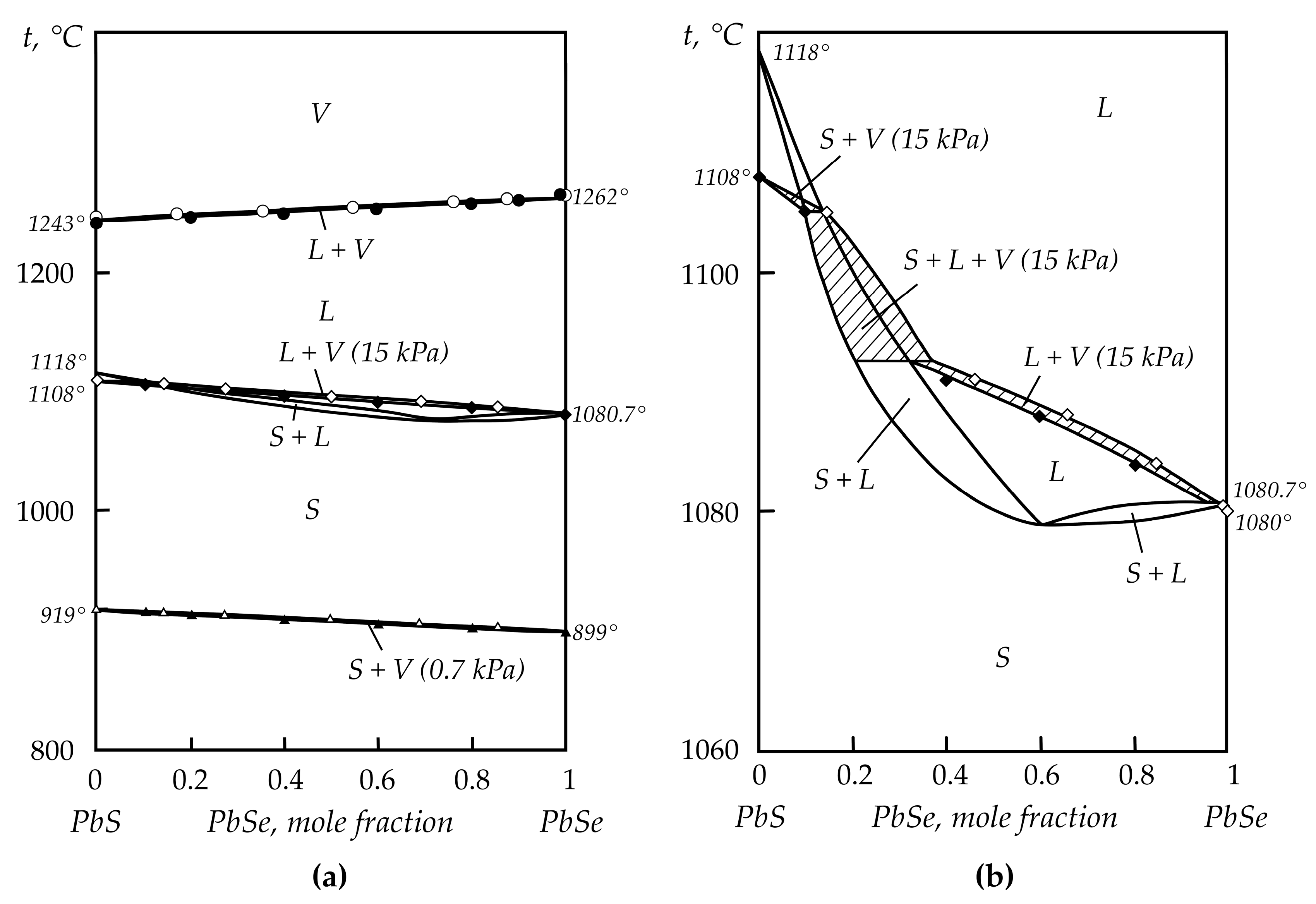
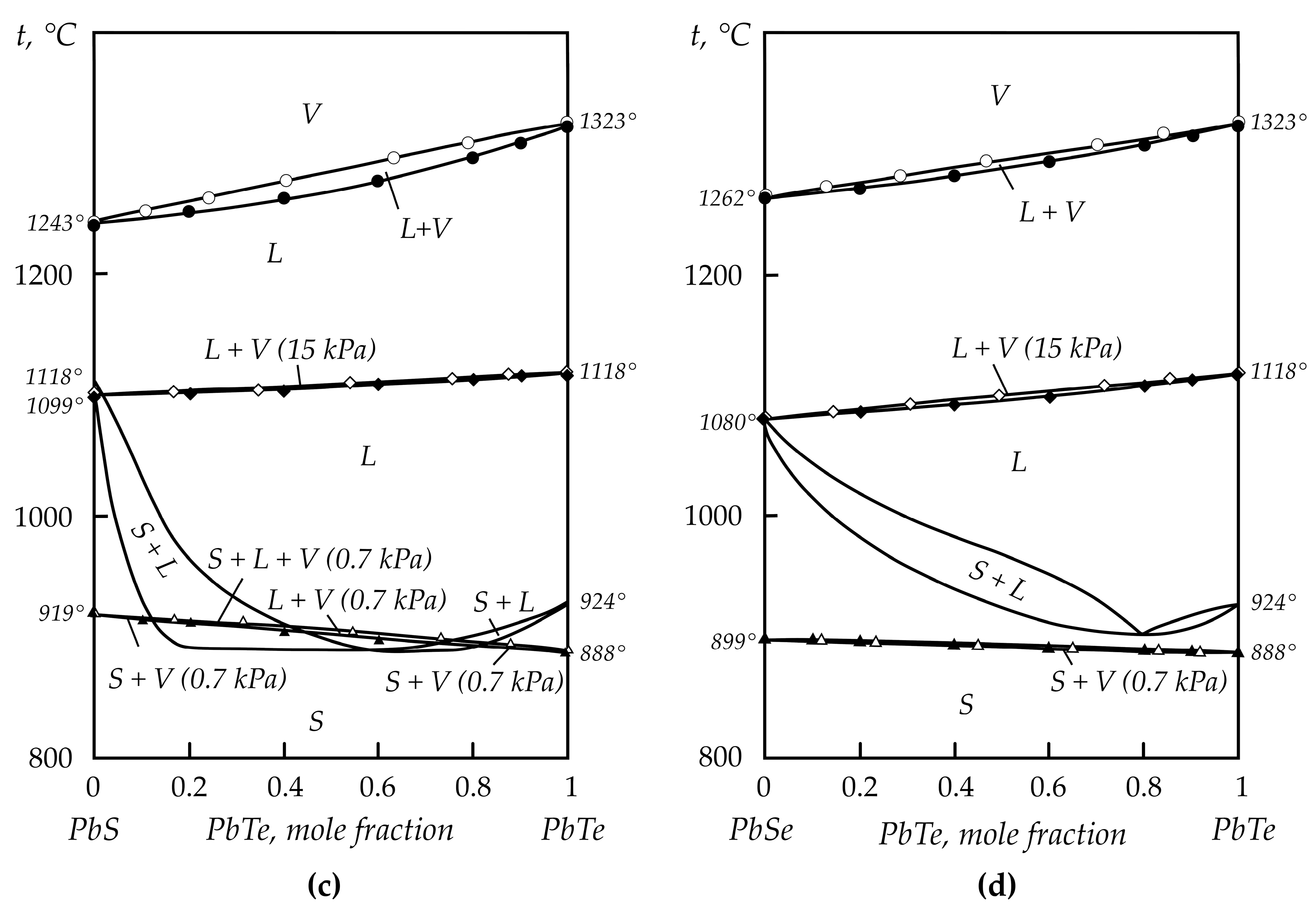
Figure 3.
State diagrams of the double systems of Cu2S—Sb2S3 (a), FeS—Sb2S3 (b), and PbS—Sb2S3. (c): 1—Our data; 2—data from [22].
Figure 3.
State diagrams of the double systems of Cu2S—Sb2S3 (a), FeS—Sb2S3 (b), and PbS—Sb2S3. (c): 1—Our data; 2—data from [22].

Figure 4.
Scheme of vacuum unit for distillation processing of matte: (1) vacuum electric furnace; (2) loading hatch; (3) blast-hole hatch; (4) vapor line; (5) condenser; (6) tank for condensate; (7) bag filter; (8) cyclone dust collector; (9) hopper; (10) oil filters; (11) vacuum pumps.
Figure 4.
Scheme of vacuum unit for distillation processing of matte: (1) vacuum electric furnace; (2) loading hatch; (3) blast-hole hatch; (4) vapor line; (5) condenser; (6) tank for condensate; (7) bag filter; (8) cyclone dust collector; (9) hopper; (10) oil filters; (11) vacuum pumps.
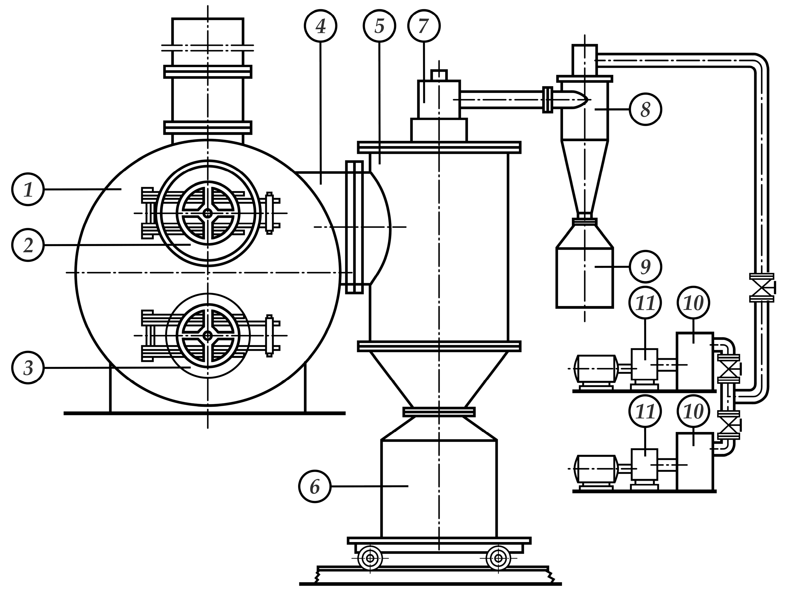
Figure 5.
Scheme of vacuum electric furnace for distillation processing of matte: (1) lined body; (2) graphite electrodes; (3) electrical pathway; (4) bus bars; (5) vapor line; (6) priming hatch; (7) blast-hole.
Figure 5.
Scheme of vacuum electric furnace for distillation processing of matte: (1) lined body; (2) graphite electrodes; (3) electrical pathway; (4) bus bars; (5) vapor line; (6) priming hatch; (7) blast-hole.

Table 1.
Mineralogical composition of raw materials processed at lead–zinc plants.
| Matte | Composition and Approximate Content of Minerals, Mass. % |
|---|---|
| Lead concentrate I | FeS2—40, PbS—40, ZnS—10, silicates—10, spinel grains |
| Lead concentrate II | PbS—50, ZnS—10, FeS2, CuFeS, silicates, Cu2S |
| Lead concentrate III | PbS—60, FeS2—20, ZnS—5, silicates—10, grains of chalcopyrite, bornite, chalcocite |
| Shared concentrate I | Galena, bornite, chalcopyrite |
| Shared concentrate II | PbS, ZnS, FeS2, carbonates |
| Shared concentrate III | ZnS—40, PbS—30, FeS2—10, Cu2S—5 |
| Copper–lead concentrate I | PbS—30, Cu2S—10, bornite —10, silicates—40, CuS, chalcopyrite—5, Cu2S—CuS solid solution |
| Copper–lead concentrate II | Cu2S—25, bornite—30, ZnS—3, chalcopyrite, Fe2O3 |
Table 2.
Concentration of basic metals and rare elements in matte.
| Matte | Element Content, wt. % | |||||||
|---|---|---|---|---|---|---|---|---|
| Cu | Fe | Sb | As | Cd | Bi | In | Ge | |
| Reflection smelting of the lead plant | 55.00 | 4.50 | 0.19 | 2.03 | 0.48 | 1 × 10⁻² | (1–3) × 10−2 | 1 × 10⁻³ |
| Reduction smelting of the lead plant | 39.37 | 14.43 | 0.17 | 0.67 | – | 1 × 10⁻³ | – | – |
| Copper plant | 38.00 | 14.32 | 0.30 | 0.65 | 0.30 | – | – | – |
| Antimony production | – | 47.50 | 5.21 | 0.12 | – | 6 × 10⁻³ | – | – |
Table 3.
The distribution of rare elements during vacuum-thermal processing of matte from the reflection smelting of the lead plant.
Table 3.
The distribution of rare elements during vacuum-thermal processing of matte from the reflection smelting of the lead plant.
| Products | Mass | Sb | As | Cd | ||||
| kg | % | Content, % | Distribution, % | Content, % | Distribution, % | Content, % | Distribution, % | |
| Loaded: | ||||||||
| Matte | 3600 | 100 | 0.19 | 100 | 2.03 | 100 | 0.48 | 100 |
| Received: | ||||||||
| Distillation residue | 2680 | 74.44 | 0.15 | 58.77 | 0.24 | 8.80 | 6 × 10⁻³ | 0.93 |
| Condensation | 870 | 24.17 | 0.32 | 40.70 | 5.60 | 66.67 | 1.90 | 95.66 |
| Cyclone dust and losses | 50 | 1.39 | - | 0.53 | - | 24.53 | - | 3.41 |
| Products | Mass | Bi | In | Ge | ||||
| kg | % | Content, % | Distribution, % | Content, % | Distribution, % | Content, % | Distribution, % | |
| Loaded: | ||||||||
| Matte | 3600 | 100 | 0.19 | 100 | 2.03 | 100 | 0.48 | 100 |
| Received: | ||||||||
| Distillation residue | 2680 | 74.44 | 1 × 10⁻³ | 7.44 | 4 × 10⁻⁴ | 0.99 | 1 × 10⁻⁴ | 7.44 |
| Condensation | 870 | 24.17 | 3 × 10⁻² | 72.50 | 0.11 | 88.61 | 3 × 10⁻³ | 72.50 |
| Cyclone dust and losses | 50 | 1.39 | - | 20.06 | - | 10.40 | - | 20.06 |
Table 4.
Distribution of rare elements during vacuum-thermal processing of matte from the reduction smelting of the lead plant.
Table 4.
Distribution of rare elements during vacuum-thermal processing of matte from the reduction smelting of the lead plant.
| Products | Mass | Sb | As | |||
| kg | % | Content, % | Distribution, % | Content, % | Distribution, % | |
| Loaded: | ||||||
| Matte | 3450 | 100 | 0.17 | 100 | 0.67 | 100 |
| Received: | ||||||
| Distillation residue | 2520 | 73.04 | 0.11 | 47.26 | 0.18 | 19.62 |
| Condensation | 900 | 26.09 | 0.31 | 47.57 | 1.59 | 61.91 |
| Cyclone dust and losses | 30 | 0.87 | - | 5.17 | - | 18.47 |
| Products | Mass | Cd | Bi | |||
| kg | % | Content, % | Distribution, % | Content, % | Distribution, % | |
| Loaded: | ||||||
| Matte | 3450 | 100 | 0.23 | 100 | 1 × 10⁻² | 100 |
| Received: | ||||||
| Distillation residue | 2520 | 73.04 | 5 × 10⁻³ | 1.59 | 1 × 10⁻³ | 7.30 |
| Condensation | 900 | 26.09 | 0.73 | 82.80 | 3 × 10⁻² | 78.26 |
| Cyclone dust and losses | 30 | 0.87 | - | 15.61 | - | 14.44 |
Table 5.
Distribution of rare elements during vacuum-thermal processing of matte from the copper-smelting plant and reduction smelting (*—calculated content).
Table 5.
Distribution of rare elements during vacuum-thermal processing of matte from the copper-smelting plant and reduction smelting (*—calculated content).
| Products | Mass | Sb | As | Cd | ||||
|---|---|---|---|---|---|---|---|---|
| kg | % | Content, % | Distribution, % | Content, % | Distribution, % | Content, % | Distribution, % | |
| Loaded: | ||||||||
| Matte from the reduction smelting | 850 | 31.48 | 0.30 | 17.95 | 0.65 | 39.89 | 0.23 | 100 |
| Matte from the copper-smelting plant | 1850 | 68.52 | 0.63 | 82.05 | 0.45 | 60.11 | - | - |
| Total: | 2700 | 100 | 0.53* | 100 | 0.51 * | 100 | 7 × 10⁻² * | 100 |
| Received: | ||||||||
| Distillation residue | 2255 | 83.52 | 6 × 10⁻² | 9.53 | 0.13 | 21.17 | 4 × 10⁻³ | 1.28 |
| Condensation | 345 | 12.78 | 3.14 | 76.26 | 2.23 | 55.55 | 0.47 | 82.94 |
| Cyclone dust and losses | 100 | 3.70 | - | 14.21 | - | 23.28 | - | 15.78 |
Table 6.
Distribution of rare elements during vacuum-thermal processing of antimony matte.
| Products | Mass | Sb | As | Bi | ||||
|---|---|---|---|---|---|---|---|---|
| kg | % | Content, % | Distribution, % | Content, % | Distribution, % | Content, % | Distribution, % | |
| Loaded: | ||||||||
| Matte | 230 | 100 | 5.21 | 100 | 0.12 | 100 | 6 ×10⁻³ | 100 |
| Received: | ||||||||
| Distillation residue | 201.4 | 87.57 | 0.55 | 9.24 | 5 × 10⁻² | 36.49 | 7 × 10⁻⁴ | 10.22 |
| Condensation | 12.5 | 5.43 | 71.57 | 74.66 | 1.02 | 46.20 | 8 × 10⁻² | 72.46 |
| Cyclone dust and losses | 16.1 | 7.00 | - | 16.10 | - | 17.31 | - | 17.32 |
Disclaimer/Publisher’s Note: The statements, opinions and data contained in all publications are solely those of the individual author(s) and contributor(s) and not of MDPI and/or the editor(s). MDPI and/or the editor(s) disclaim responsibility for any injury to people or property resulting from any ideas, methods, instructions or products referred to in the content. |
© 2023 by the authors. Licensee MDPI, Basel, Switzerland. This article is an open access article distributed under the terms and conditions of the Creative Commons Attribution (CC BY) license (https://creativecommons.org/licenses/by/4.0/).
Share and Cite
MDPI and ACS Style
Volodin, V.; Nitsenko, A.; Linnik, X.; Trebukhov, S. Distribution of Rare Elements in Distillation Processing of Polymetallic Matte. Metals 2023, 13, 1934. https://doi.org/10.3390/met13121934
AMA Style
Volodin V, Nitsenko A, Linnik X, Trebukhov S. Distribution of Rare Elements in Distillation Processing of Polymetallic Matte. Metals. 2023; 13(12):1934. https://doi.org/10.3390/met13121934
Chicago/Turabian StyleVolodin, Valeriy, Alina Nitsenko, Xeniya Linnik, and Sergey Trebukhov. 2023. "Distribution of Rare Elements in Distillation Processing of Polymetallic Matte" Metals 13, no. 12: 1934. https://doi.org/10.3390/met13121934
Note that from the first issue of 2016, this journal uses article numbers instead of page numbers. See further details here.