
Corrosion Behavior of High Entropy Alloys and Their Application in the Nuclear Industry—An Overview


Abstract
:1. Introduction
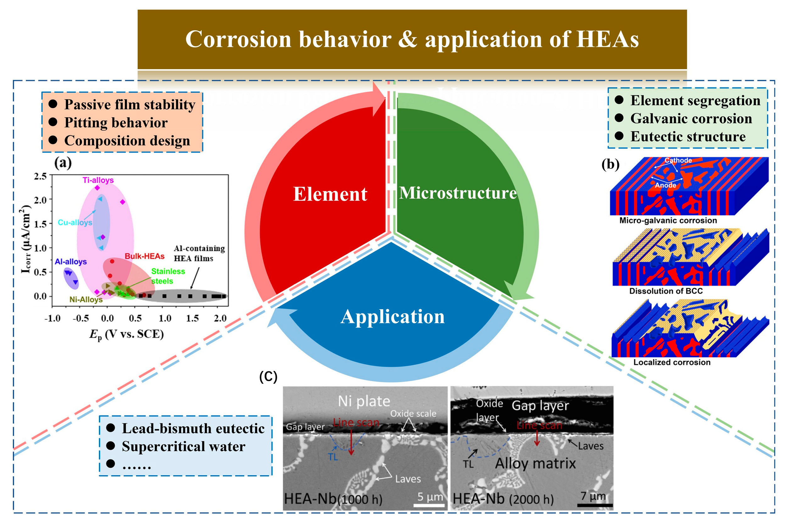
2. Influence of Elements on the Corrosion of HEAs
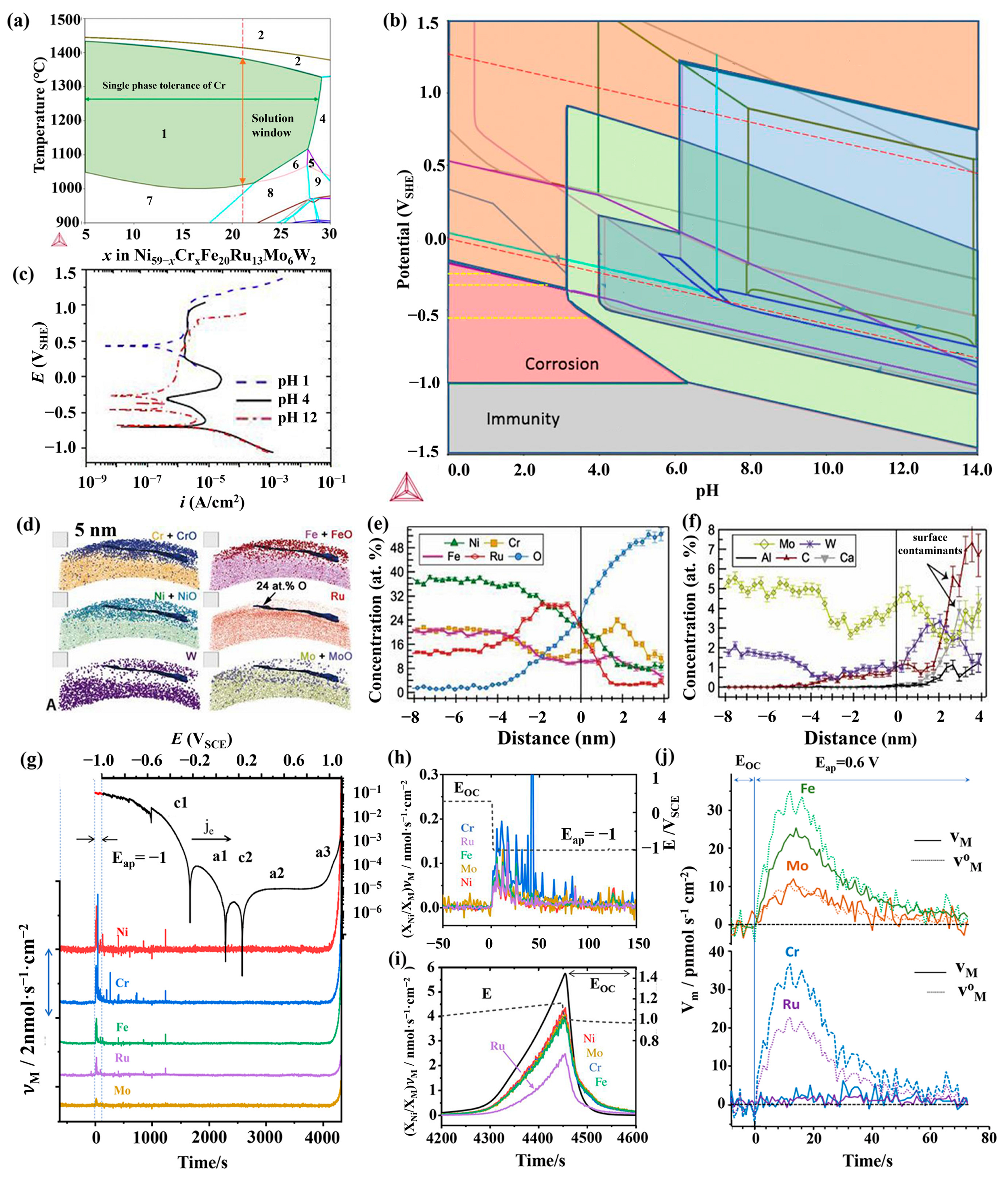
2.1. Chromium
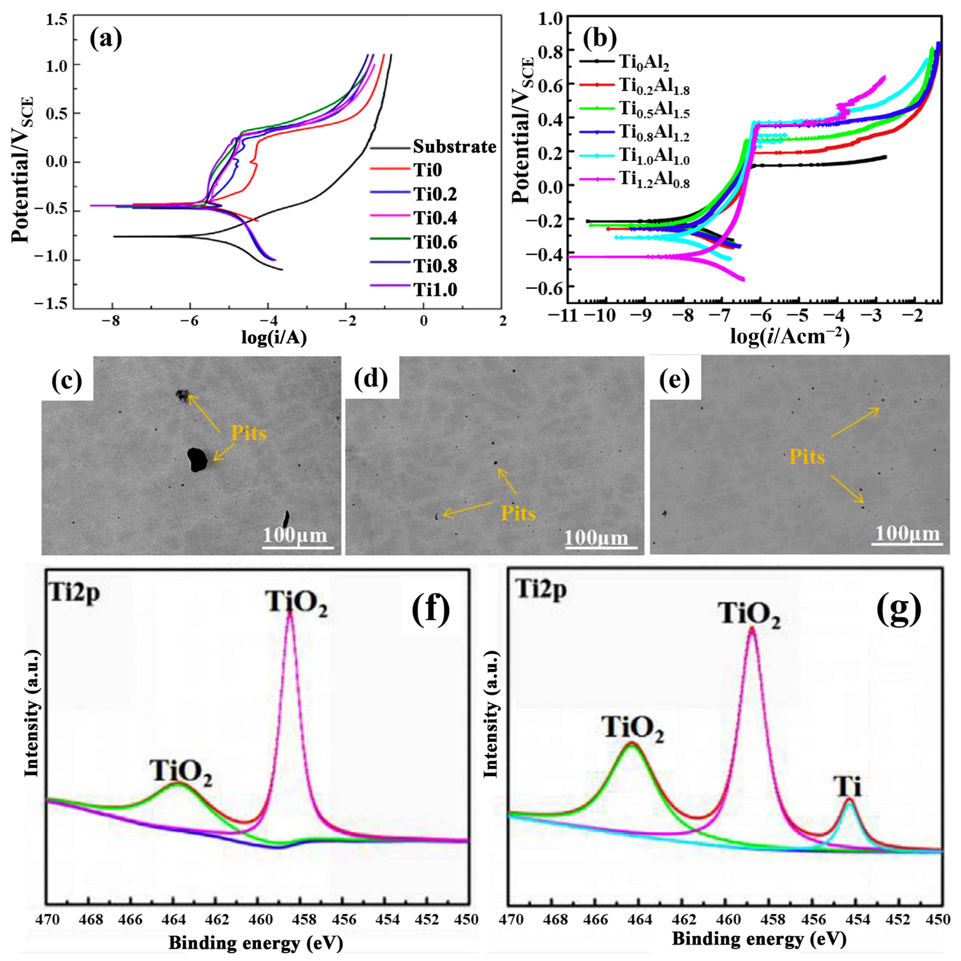
2.2. Titanium
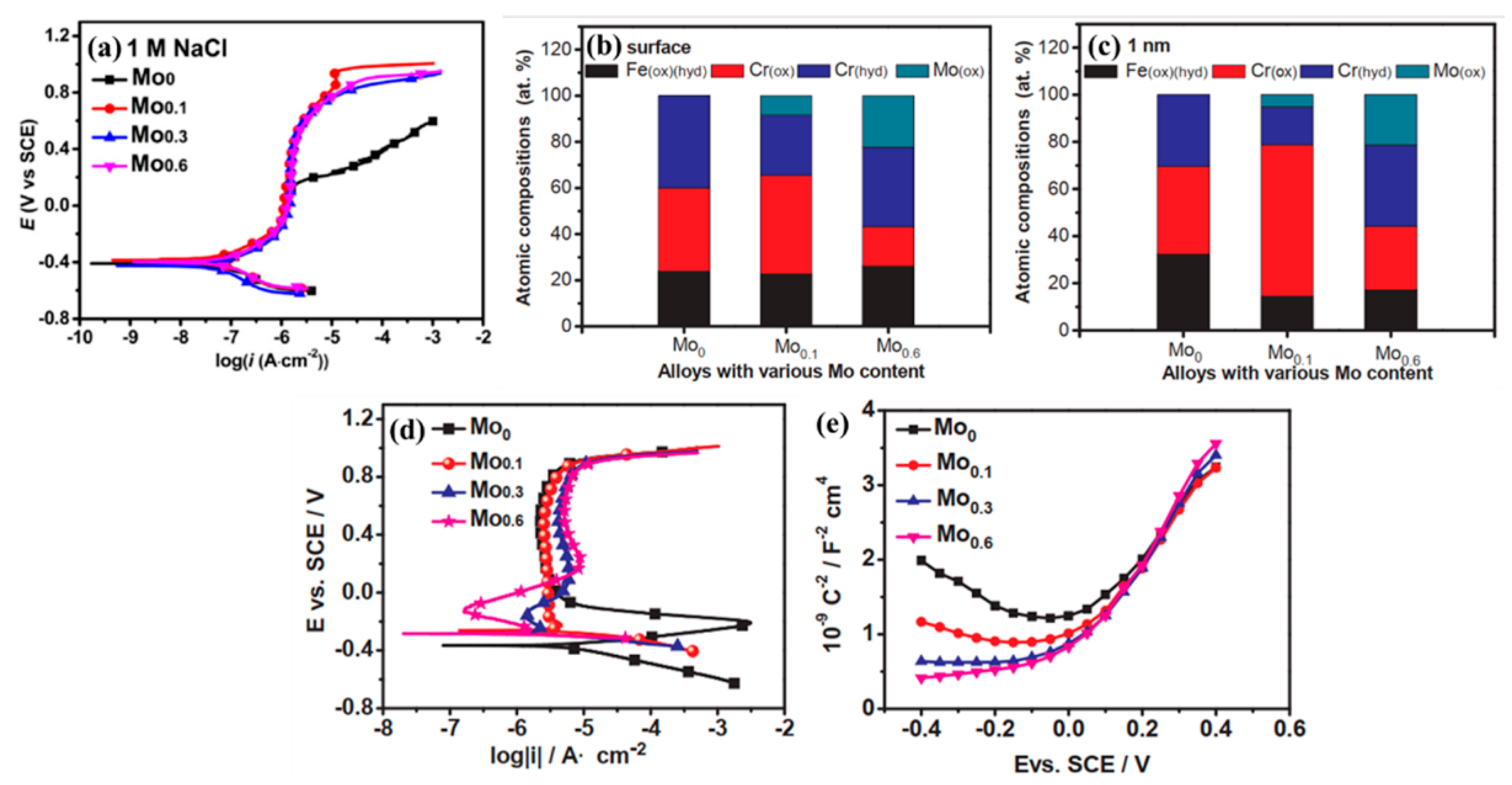
2.3. Molybdenum
2.4. Nickel
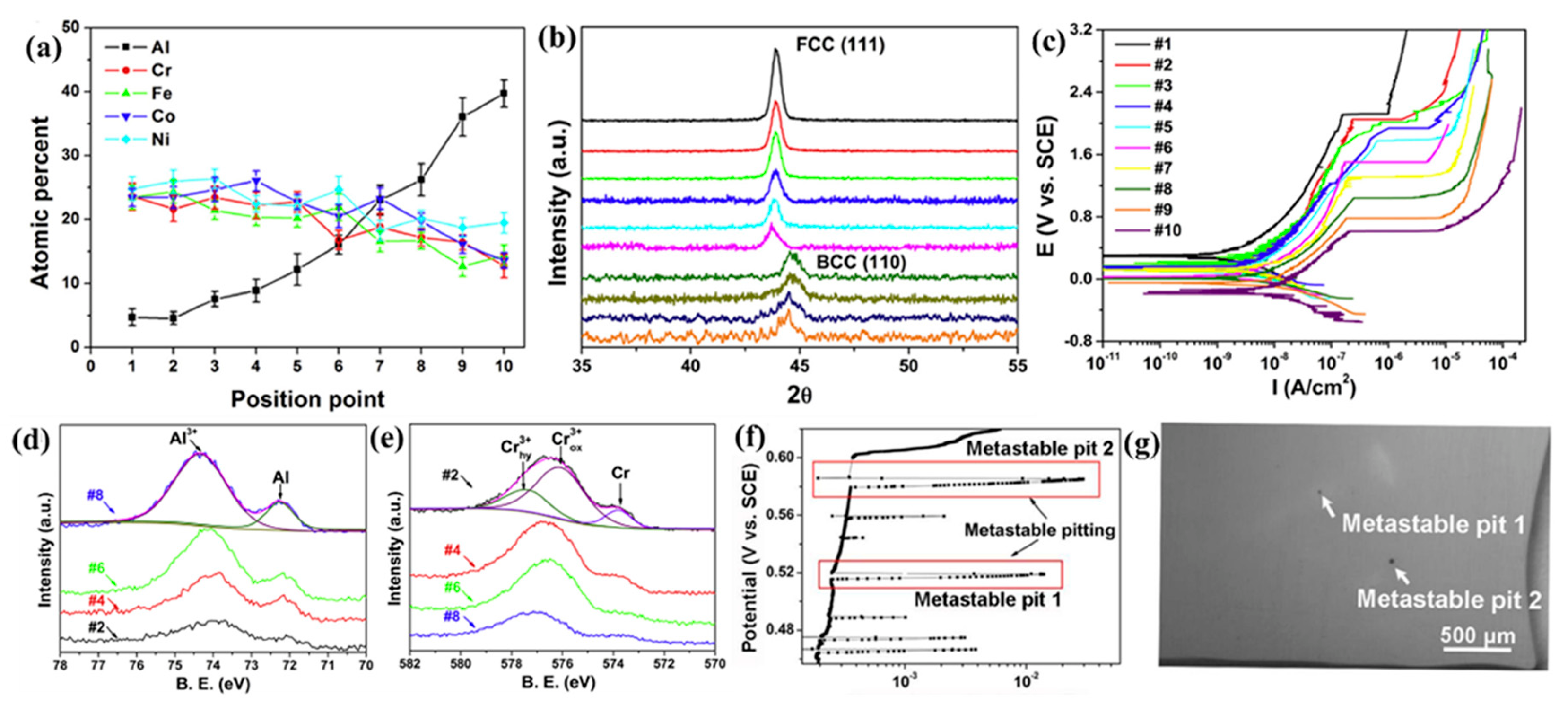
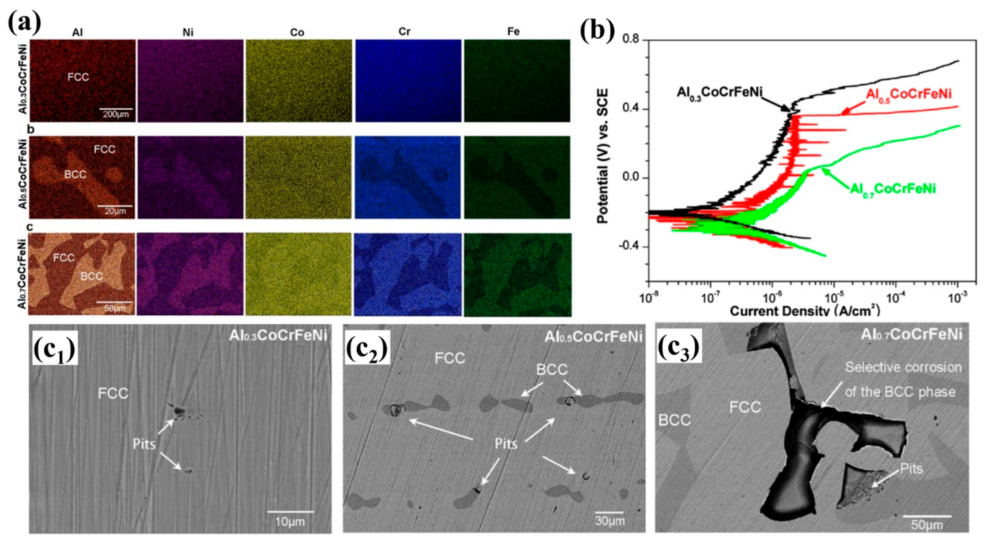
2.5. Aluminum
2.6. Manganese
2.7. Other Metallic Elements
2.8. Non-Metallic Elements
2.9. Design of High Corrosion Resistant HEAs
3. Influence of Structure on the Corrosion of HEAs
3.1. Single-Phase Solid Solution
3.1.1. Dendritic Segregation
3.1.2. Grain Size
3.2. Multi-Phase Solid Solution
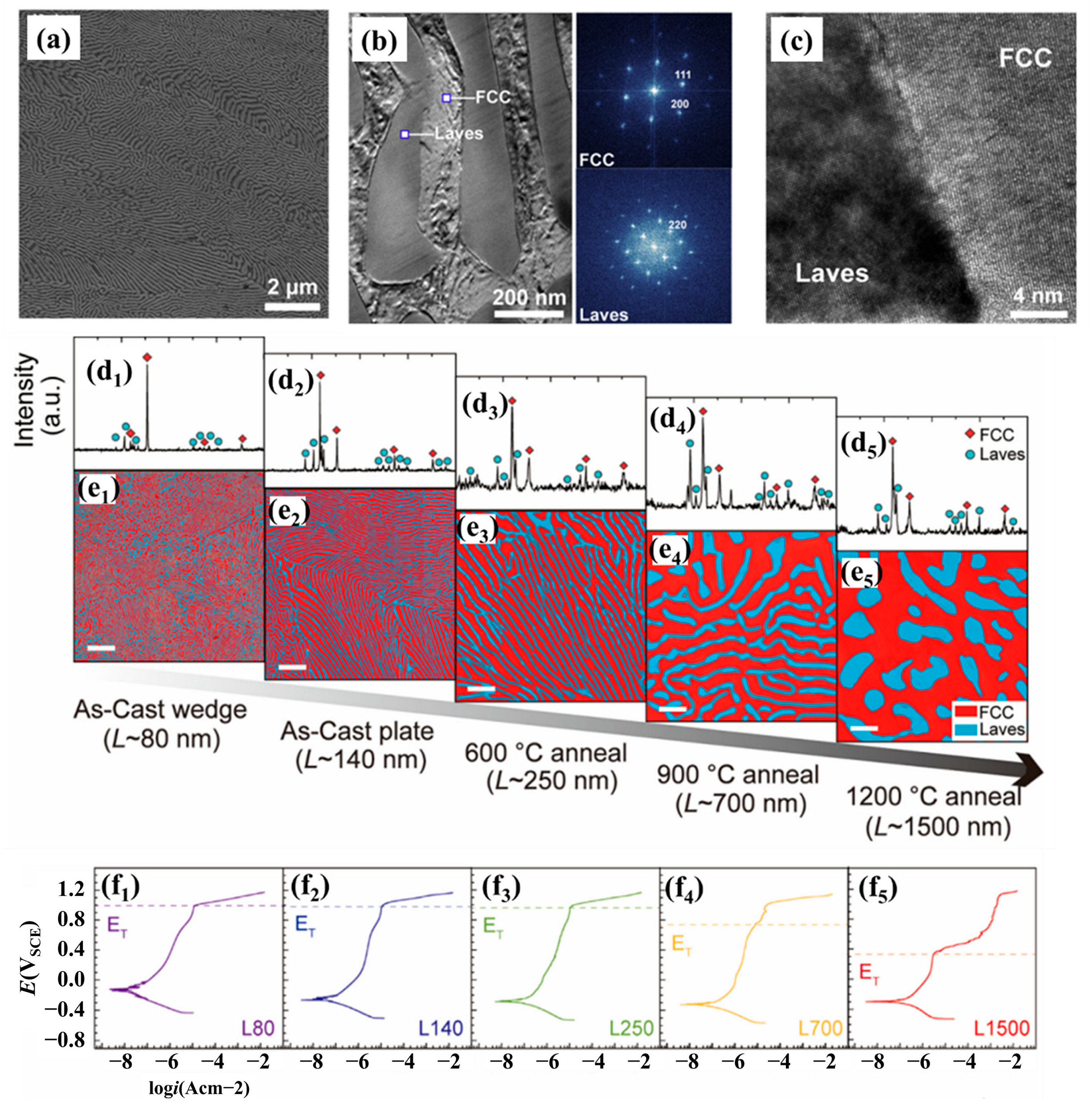
3.3. Eutectic High Entropy Alloys
4. Application for the Nuclear Industry
4.1. Lead–Bismuth Eutectic Environment
4.2. Supercritical Water Environment
5. Conclusions
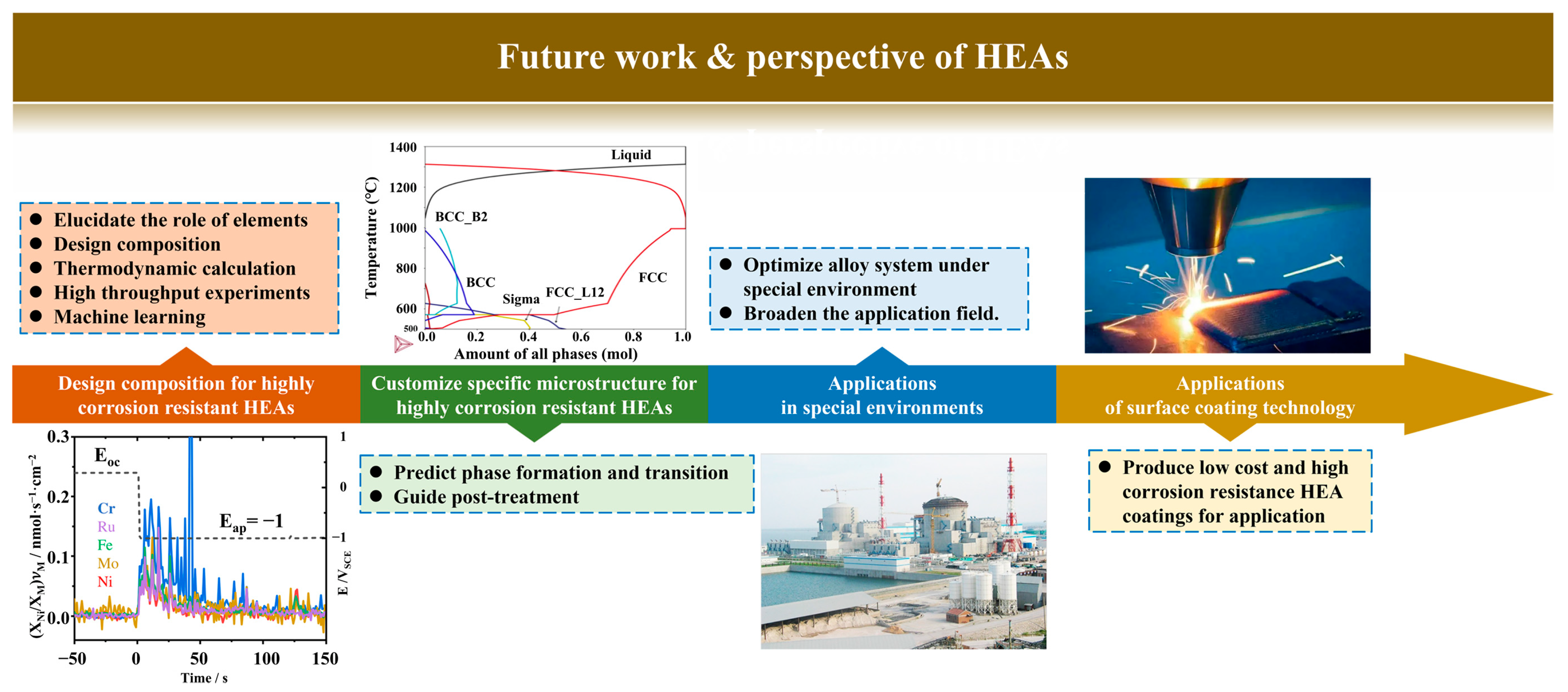
6. Future Work
6.1. Composition Design for Highly Corrosion Resistant HEAs
6.2. Tailoring Specific Microstructure for Highly Corrosion Resistant HEAs
6.3. Applications in Special Environments
6.4. Applications of Surface Coating Technology
Author Contributions
Funding
Data Availability Statement
Acknowledgments
Conflicts of Interest
References
- Yeh, J.-W.; Chen, S.K.; Lin, S.-J.; Gan, J.-Y.; Chin, T.-S.; Shun, T.-T.; Tsau, C.-H.; Chang, S.-Y. Nanostructured High-Entropy Alloys with Multiple Principal Elements: Novel Alloy Design Concepts and Outcomes. Adv. Eng. Mater. 2004, 6, 299–303. [Google Scholar] [CrossRef]
- Yeh, J.-W.; Chang, S.-Y.; Hong, Y.-D.; Chen, S.-K.; Lin, S.-J. Anomalous decrease in X-ray diffraction intensities of Cu–Ni–Al–Co–Cr–Fe–Si alloy systems with multi-principal elements. Mater. Chem. Phys. 2007, 103, 41–46. [Google Scholar] [CrossRef]
- Tsai, K.; Tsai, M.; Yeh, J. Sluggish diffusion in Co–Cr–Fe–Mn–Ni high-entropy alloys. Acta Mater. 2013, 61, 4887–4897. [Google Scholar] [CrossRef]
- Wang, X.; Mercier, D.; Danard, Y.; Rieger, T.; Perrière, L.; Laurent-Brocq, M.; Guillot, I.; Maurice, V.; Marcus, P. Enhanced passivity of Cr-Fe-Co-Ni-Mo multi-component single-phase face-centred cubic alloys: Design, production and corrosion behaviour. Corros. Sci. 2022, 200, 110233. [Google Scholar] [CrossRef]
- Senkov, O.N.; Miracle, D.B.; Chaput, K.J.; Couzinie, J.-P. Development and exploration of refractory high entropy alloys—A review. J. Mater. Res. 2018, 33, 3092–3128. [Google Scholar] [CrossRef]
- Nagase, T.; Rack, P.; Noh, J.; Egami, T. In-situ TEM observation of structural changes in nano-crystalline CoCrCuFeNi multi-component high-entropy alloy (HEA) under fast electron irradiation by high voltage electron microscopy (HVEM). Intermetallics 2015, 59, 32–42. [Google Scholar] [CrossRef]
- Kumar, N.A.P.K.; Li, C.; Leonard, K.J.; Bei, H.; Zinkle, S.J. Microstructural stability and mechanical behavior of FeNiMnCr high entropy alloy under ion irradiation. Acta Mater. 2016, 113, 230–244. [Google Scholar] [CrossRef]
- Lu, Y.; Huang, H.; Gao, X.; Ren, C.; Gao, J.; Zhang, H.; Zheng, S.; Jin, Q.; Zhao, Y.; Lu, C.; et al. A promising new class of ir-radiation tolerant materials: Ti2ZrHfV0.5Mo0.2 high-entropy alloy. J. Mater. Sci. Technol. 2019, 35, 369–373. [Google Scholar] [CrossRef]
- Zhao, Y.; Wang, M.; Cui, H.; Zhao, Y.; Song, X.; Zeng, Y.; Gao, X.; Lu, F.; Wang, C.; Song, Q. Effects of Ti-to-Al ratios on the phases, microstructures, mechanical properties, and corrosion resistance of Al2-xCoCrFeNiTix high-entropy alloys. J. Alloys Compd. 2019, 805, 585–596. [Google Scholar] [CrossRef]
- Öztürk, S.; Alptekin, F.; Önal, S.; Sünbül, S.E.; Şahin, Ö.; Için, K. Effect of titanium addition on the corrosion behavior of CoCuFeNiMn high entropy alloy. J. Alloys Compd. 2022, 903, 163867. [Google Scholar] [CrossRef]
- Chou, Y.; Yeh, J.; Shih, H. The effect of molybdenum on the corrosion behaviour of the high-entropy alloys Co1.5CrFeNi1.5Ti0.5Mox in aqueous environments. Corros. Sci. 2010, 52, 2571–2581. [Google Scholar] [CrossRef]
- Jiang, S.; Lin, Z.; Xu, H.; Sun, Y. Studies on the microstructure and properties of AlxCoCrFeNiTi1-x high entropy alloys. J. Alloys Compd. 2018, 741, 826–833. [Google Scholar] [CrossRef]
- Luo, H.; Zou, S.; Chen, Y.-H.; Li, Z.; Du, C.; Li, X. Influence of carbon on the corrosion behaviour of interstitial equiatomic CoCrFeMnNi high-entropy alloys in a chlorinated concrete solution. Corros. Sci. 2020, 163, 108287. [Google Scholar] [CrossRef]
- Zhou, Q.; Sheikh, S.; Ou, P.; Chen, D.; Hu, Q.; Guo, S. Corrosion behavior of Hf0.5Nb0.5Ta0.5Ti1.5Zr refractory high-entropy in aqueous chloride solutions. Electrochem. Commun. 2019, 98, 63–68. [Google Scholar] [CrossRef]
- Zhao, Y.; Qiao, J.; Ma, S.; Gao, M.; Yang, H.; Chen, M.; Zhang, Y. A hexagonal close-packed high-entropy alloy: The effect of entropy. Mater. Des. 2016, 96, 10–15. [Google Scholar] [CrossRef]
- Shi, Y.; Collins, L.; Balke, N.; Liaw, P.; Yang, B. In-situ electrochemical-AFM study of localized corrosion of AlxCoCrFeNi high-entropy alloys in chloride solution. Appl. Surf. Sci. 2018, 439, 533–544. [Google Scholar] [CrossRef]
- Shi, Y.; Collins, L.; Feng, R.; Zhang, C.; Balke, N.; Liaw, P.; Yang, B. Homogenization of AlxCoCrFeNi high-entropy alloys with improved corrosion resistance. Corros. Sci. 2018, 133, 120–131. [Google Scholar] [CrossRef]
- Gong, X.; Short, M.P.; Auger, T.; Charalampopoulou, E.; Lambrinou, K. Environmental degradation of structural materials in liquid lead- and lead-bismuth eutectic-cooled reactors. Prog. Mater. Sci. 2022, 126, 100920. [Google Scholar] [CrossRef]
- Gong, X.; Auger, T.; Zhu, W.; Lei, H.; Xiang, C.; Yu, Z.; Short, M.P.; Wang, P.; Yin, Y. Intergranular precipitation-enhanced wetting and phase transformation in an Al0.4CoCrFeNi high-entropy alloy exposed to lead-bismuth eutectic. Corros. Sci. 2022, 196, 110038. [Google Scholar] [CrossRef]
- Yang, J.; Shi, K.; Zhang, W.; Chen, Q.; Ning, Z.; Zhu, C.; Liao, J.; Yang, Y.; Liu, N.; Yang, J. A novel AlCrFeMoTi high-entropy alloy coating with a high corrosion-resistance in lead-bismuth eutectic alloy. Corros. Sci. 2021, 187, 109524. [Google Scholar] [CrossRef]
- Pint, B.A. Performance of FeCrAl for accident-tolerant fuel cladding in high-temperature steam. Corros. Rev. 2017, 35, 167–175. [Google Scholar] [CrossRef]
- Daghbouj, N.; Li, B.; Callisti, M.; Sen, H.S.; Karlik, M.; Polcar, T. Microstructural evolution of helium-irradiated 6H–SiC subjected to different irradiation conditions and annealing temperatures: A multiple characterization study. Acta Mater. 2019, 181, 160–172. [Google Scholar] [CrossRef]
- Daghbouj, N.; Li, B.; Callisti, M.; Sen, H.; Lin, J.; Ou, X.; Karlik, M.; Polcar, T. The structural evolution of light-ion implanted 6H-SiC single crystal: Comparison of the effect of helium and hydrogen. Acta Mater. 2020, 188, 609–622. [Google Scholar] [CrossRef]
- Shi, H.; Jianu, A.; Fetzer, R.; Szabó, D.V.; Schlabach, S.; Weisenburger, A.; Tang, C.; Heinzel, A.; Lang, F.; Müller, G. Compatibility and microstructure evolution of Al-Cr-Fe-Ni high entropy model alloys exposed to oxygen-containing molten lead. Corros. Sci. 2021, 189, 109593. [Google Scholar] [CrossRef]
- Shi, Y.; Yang, B.; Rack, P.; Guo, S.; Liaw, P.; Zhao, Y. High-throughput synthesis and corrosion behavior of sputter-deposited nanocrystalline Alx(CoCrFeNi)100-x combinatorial high-entropy alloys. Mater. Des. 2020, 195, 109018. [Google Scholar] [CrossRef]
- Shi, H.; Fetzer, R.; Jianu, A.; Weisenburger, A.; Heinzel, A.; Lang, F.; Müller, G. Influence of alloying elements (Cu, Ti, Nb) on the microstructure and corrosion behaviour of AlCrFeNi-based high entropy alloys exposed to oxygen-containing molten Pb. Corros. Sci. 2021, 190, 109659. [Google Scholar] [CrossRef]
- Wei, L.; Qin, W. Corrosion mechanism of eutectic high-entropy alloy induced by micro-galvanic corrosion in sulfuric acid solution. Corros. Sci. 2022, 206, 110525. [Google Scholar] [CrossRef]
- Yan, X.; Guo, H.; Yang, W.; Pang, S.; Wang, Q.; Liu, Y.; Liaw, P.K.; Zhang, T. Al0.3CrxFeCoNi high-entropy alloys with high corrosion resistance and good mechanical properties. J. Alloys Compd. 2020, 860, 158436. [Google Scholar] [CrossRef]
- Yang, S.; Yu, W.; Liu, T.; Li, C.; Zhang, Y.; Qu, Y. Effect of Cr content on corrosion behavior of AlCrxFeNi2Cu1.6 high entropy alloys. Mater. Res. Express. 2019, 6, 076501. [Google Scholar] [CrossRef]
- Shimizu, H.; Yuasa, M.; Miyamoto, H.; Edalati, K. Corrosion Behavior of Ultrafine-Grained CoCrFeMnNi High-Entropy Alloys Fabricated by High-Pressure Torsion. Materials 2022, 15, 1007. [Google Scholar] [CrossRef]
- Tsau, C.-H.; Tsai, M.-C.; Wang, W.-L. Microstructures of FeCoNiMo and CrFeCoNiMo Alloys, and the Corrosion Properties in 1 M Nitric Acid and 1 M Sodium Chloride Solutions. Materials 2022, 15, 888. [Google Scholar] [CrossRef]
- Chai, W.; Lu, T.; Pan, Y. Corrosion behaviors of FeCoNiCr (x = 0, 0.5, 1.0) multi-principal element alloys: Role of Cr-induced segregation. Intermetallics 2020, 116, 106654. [Google Scholar] [CrossRef]
- Feng, H.; Li, H.-B.; Dai, J.; Han, Y.; Qu, J.-D.; Jiang, Z.-H.; Zhao, Y.; Zhang, T. Why CoCrFeMnNi HEA could not passivate in chloride solution?—A novel strategy to significantly improve corrosion resistance of CoCrFeMnNi HEA by N-alloying. Corros. Sci. 2022, 204, 110396. [Google Scholar] [CrossRef]
- Liu, J.; Liu, H.; Chen, P.; Hao, J. Microstructural characterization and corrosion behaviour of AlCoCrFeNiTix high-entropy alloy coatings fabricated by laser cladding. Surf. Coatings Technol. 2019, 361, 63–74. [Google Scholar] [CrossRef]
- Brox, B.; Yi-Hua, W.; Olefjord, I. Electrochemical and Surface Analyses of Mo (100) Single Crystal Polarized in 0.5 M H2 SO4. J. Electrochem. Soc. 1988, 135, 2184–2187. [Google Scholar] [CrossRef]
- Falkenberg, F.; Raja, V.; Ahlberg, E. An Alternative Explanation for the Apparent Passivation of Molybdenum in 1 mol/L Hy-drochloric Acid. J. Electrochem. Soc. 2001, 148, B132–B137. [Google Scholar] [CrossRef]
- Shang, X.-L.; Wang, Z.-J.; Wu, Q.-F.; Wang, J.-C.; Li, J.-J.; Yu, J.-K. Effect of Mo Addition on Corrosion Behavior of High-Entropy Alloys CoCrFeNiMox in Aqueous Environments. Acta Met. Sin. 2018, 32, 41–51. [Google Scholar] [CrossRef]
- Dai, C.; Luo, H.; Li, J.; Du, C.; Liu, Z.; Yao, J. X-ray photoelectron spectroscopy and electrochemical investigation of the passive behavior of high-entropy FeCoCrNiMox alloys in sulfuric acid. Appl. Surf. Sci. 2020, 499, 143903. [Google Scholar] [CrossRef]
- Glowka, K.; Zubko, M.; Swiec, P.; Prusik, K.; Szklarska, M.; Chrobak, D.; Labar, J.; Stroz, D. Influence of Molybdenum on the Microstructure, Mechanical Properties and Corrosion Resistance of Ti20Ta20Nb20(ZrHf)20-xMox (Where: X=0, 5, 10, 15, 20) High Entropy Alloys. Materials 2022, 15, 393. [Google Scholar] [CrossRef]
- Wang, J.; Chen, Y.; Zhang, Y.; Zhang, Y.; Li, J.; Liu, J.; Liu, Y.; Li, W. Microstructure evolution and acid corrosion behavior of CoCrFeNiCu1−xMox high-entropy alloy coatings fabricated by coaxial direct laser deposition. Corros. Sci. 2022, 198, 110108. [Google Scholar] [CrossRef]
- Dai, C.; Zhao, T.; Du, C.; Liu, Z.; Zhang, D. Effect of molybdenum content on the microstructure and corrosion behavior of FeCoCrNiMox high-entropy alloys. J. Mater. Sci. Technol. 2020, 46, 64–73. [Google Scholar] [CrossRef]
- Qiu, X.-W.; Liu, C.-G. Microstructure and properties of Al2CrFeCoCuTiNix high-entropy alloys prepared by laser cladding. J. Alloys Compd. 2013, 553, 216–220. [Google Scholar] [CrossRef]
- Huang, L.; Wang, X.; Zhao, X.; Wang, C.; Yang, Y. Analysis on the key role in corrosion behavior of CoCrNiAlTi-based high entropy alloy. Mater. Chem. Phys. 2021, 259, 124007. [Google Scholar] [CrossRef]
- Shi, Y.; Yang, B.; Xie, X.; Brechtl, J.; Dahmen, K.; Liaw, P. Corrosion of AlxCoCrFeNi high-entropy alloys: Al-content and potential scan-rate dependent pitting behavior. Corros. Sci. 2017, 119, 33–45. [Google Scholar] [CrossRef]
- Kao, Y.-F.; Lee, T.-D.; Chen, S.-K.; Chang, Y.-S. Electrochemical passive properties of AlxCoCrFeNi (x = 0, 0.25, 0.50, 1.00) alloys in sulfuric acids. Corros. Sci. 2010, 52, 1026–1034. [Google Scholar] [CrossRef]
- Shi, Y.; Mo, J.; Zhang, F.; Yang, B.; Liaw, P.; Zhao, Y. In-situ visualization of corrosion behavior of AlxCoCrFeNi high-entropy alloys during electrochemical polarization. J. Alloys Compd. 2020, 844, 156014. [Google Scholar] [CrossRef]
- Wong, S.-K.; Shun, T.-T.; Chang, C.-H.; Lee, C.-F. Microstructures and properties of Al0.3CoCrFeNiMnx high-entropy alloys. Mater. Chem. Phys. 2018, 210, 146–151. [Google Scholar] [CrossRef]
- Hsu, K.-M.; Chen, S.-H.; Lin, C.-S. Microstructure and corrosion behavior of FeCrNiCoMnx (x = 1.0, 0.6, 0.3, 0) high entropy alloys in 0.5 M H2SO4. Corros. Sci. 2021, 190, 109694. [Google Scholar] [CrossRef]
- Sun, S.; Liu, H.; Hao, J.; Yang, H. Microstructural evolution and corrosion behavior of CoCrFeNiAlxMn1-x dual-phase high-entropy alloy coatings prepared by laser cladding. J. Alloys Compd. 2021, 886, 161251. [Google Scholar] [CrossRef]
- Inman, S.; Han, J.; Gerard, A.; Qi, J.; Wischhusen, M.; Agnew, S.; Poon, S.; Ogle, K.; Scully, J. Effect of Mn Content on the Passivation and Corrosion of Al0.3Cr0.5Fe2MnxMo0.15Ni1.5Ti0.3 Compositionally Complex Face-Centered Cubic Alloys. Corrosion 2022, 78, 32–48. [Google Scholar] [CrossRef]
- Yang, J.; Wu, J.; Zhang, C.; Zhang, S.; Yang, B.; Emori, W.; Wang, J. Effects of Mn on the electrochemical corrosion and pas-sivation behavior of CoFeNiMnCr high-entropy alloy system in H2SO4 solution. J. Alloys Compd. 2020, 819, 152943. [Google Scholar] [CrossRef]
- Han, J.; Li, X.; Gerard, A.; Lu, P.; Saal, J.; Frankel, G.; Ogle, K.; Scully, J. Potential Dependent Mn Oxidation and Its Role in Passivation of Ni38Fe20Cr22Mn10Co10 Multi-Principal Element Alloy Using Multi-Element Resolved Atomic Emission Spectroelec-trochemistry. J. Electrochem. Soc. 2021, 168, 051508. [Google Scholar] [CrossRef]
- Torbati-Sarraf, H.; Shabani, M.; Jablonski, P.D.; Pataky, G.J.; Poursaee, A. The influence of incorporation of Mn on the pitting corrosion performance of CrFeCoNi High Entropy Alloy at different temperatures. Mater. Des. 2019, 184, 108170. [Google Scholar] [CrossRef]
- Zhang, S.; Zhang, Z.; He, P.; Hu, Z.; Jing, Z.; Gao, Y.; Liang, X. Role of Co content on the microstructure and anti-corrosion per-formance of high-hardness AlNiYCox high entropy metallic glasses. J. Non-Cryst. Solids 2022, 576, 121268. [Google Scholar] [CrossRef]
- Fan, Q.; Chen, C.; Fan, C.; Liu, Z.; Cai, X.; Lin, S.; Yang, C. Effect of high Fe content on the microstructure, mechanical and corrosion properties of AlCoCrFeNi high-entropy alloy coatings prepared by gas tungsten arc cladding. Surf. Coat. Technol. 2021, 418, 127242. [Google Scholar] [CrossRef]
- Wen, X.; Cui, X.; Jin, G.; Liu, Y.; Zhang, Y.; Zhang, X.; Liu, E.; Tian, H.; Fang, Y. Corrosion and tribo-corrosion behaviors of nano-lamellar Ni1.5CrCoFe0.5Mo0.1Nbx eutectic high-entropy alloy coatings: The role of dual-phase microstructure. Corros. Sci. 2022, 201, 110305. [Google Scholar] [CrossRef]
- Niu, Z.; Xu, J.; Wang, T.; Wang, N.; Han, Z.; Wang, Y. Microstructure, mechanical properties and corrosion resistance of CoCrFeNiWx (x = 0, 0.2, 0.5) high entropy alloys. Intermetallics 2019, 112, 106550. [Google Scholar] [CrossRef]
- Li, X.; Zhou, P.; Feng, H.; Jiang, Z.; Li, H.; Ogle, K. Spontaneous passivation of the CoCrFeMnNi high entropy alloy in sulfuric acid solution: The effects of alloyed nitrogen and dissolved oxygen. Corros. Sci. 2022, 196, 110016. [Google Scholar] [CrossRef]
- Choudhary, S.; O’Brien, S.; Qiu, Y.; Thomas, S.; Gupta, R.; Birbilis, N. On the dynamic passivity and corrosion resistance of a low cost and low density multi-principal-element alloy produced via commodity metals. Electrochem. Commun. 2021, 125, 106989. [Google Scholar] [CrossRef]
- Scully, J.R.; Inman, S.B.; Gerard, A.Y.; Taylor, C.D.; Windl, W.; Schreiber, D.K.; Lu, P.; Saal, J.E.; Frankel, G.S. Controlling the corrosion resistance of multi-principal element alloys. Scr. Mater. 2020, 188, 96–101. [Google Scholar] [CrossRef]
- Wang, K.; Han, J.; Gerard, A.; Scully, J.; Zhou, B. Potential-pH diagrams considering complex oxide solution phases for understanding aqueous corrosion of multi-principal element alloys. Npj Mater. Degrad. 2020, 4, 11. [Google Scholar] [CrossRef]
- Gerard, A.; Han, J.; McDonnell, S.; Ogle, K.; Kautz, E.; Schreiber, D.; Lu, P.; Saal, J.; Frankel, G.; Scully, J. Aqueous passivation of multi-principal element alloy Ni38Fe20Cr22Mn10Ca10: Unexpected high Cr enrichment within the passive film. Acta Mater. 2020, 198, 121–133. [Google Scholar] [CrossRef]
- Li, X.; Han, J.; Lu, P.; Saal, J.E.; Olson, G.B.; Frankel, G.S.; Scully, J.R.; Ogle, K. Communication—Dissolution and Passivation of a Ni-Cr-Fe-Ru-Mo-W High Entropy Alloy by Elementally Resolved Electrochemistry. J. Electrochem. Soc. 2020, 167, 061505. [Google Scholar] [CrossRef]
- Lu, P.; Saal, J.E.; Olson, G.B.; Li, T.; Swanson, O.J.; Frankel, G.; Gerard, A.Y.; Quiambao, K.F.; Scully, J.R. Computational materials design of a corrosion resistant high entropy alloy for harsh environments. Scr. Mater. 2018, 153, 19–22. [Google Scholar] [CrossRef]
- Quiambao, K.F.; McDonnell, S.J.; Schreiber, D.K.; Gerard, A.Y.; Freedy, K.M.; Lu, P.; Saal, J.E.; Frankel, G.S.; Scully, J.R. Passivation of a corrosion resistant high entropy alloy in non-oxidizing sulfate solutions. Acta Mater. 2018, 164, 362–376. [Google Scholar] [CrossRef]
- Zhou, E.; Qiao, D.; Yang, Y.; Xu, D.; Lu, Y.; Wang, J.; Smith, J.A.; Li, H.; Zhao, H.; Liaw, P.K.; et al. A novel Cu-bearing high-entropy alloy with significant antibacterial behavior against corrosive marine biofilms. J. Mater. Sci. Technol. 2020, 46, 201–210. [Google Scholar] [CrossRef]
- Hsu, Y.-J.; Chiang, W.-C.; Wu, J.-K. Corrosion behavior of FeCoNiCrCux high-entropy alloys in 3.5% sodium chloride solution. Mater. Chem. Phys. 2005, 92, 112–117. [Google Scholar] [CrossRef]
- Muangtong, P.; Rodchanarowan, A.; Chaysuwan, D.; Chanlek, N.; Goodall, R. The corrosion behaviour of CoCrFeNix (x = Cu, Al, Sn) high entropy alloy systems in chloride solution. Corros. Sci. 2020, 172, 108740. [Google Scholar] [CrossRef]
- Yu, Y.; Xu, N.; Zhu, S.; Qiao, Z.; Zhang, J.; Yang, J.; Liu, W. A novel Cu-doped high entropy alloy with excellent comprehensive performances for marine application. J. Mater. Sci. Technol. 2020, 69, 48–59. [Google Scholar] [CrossRef]
- Wang, Y.; Jin, J.; Zhang, M.; Wang, X.; Gong, P.; Zhang, J.; Liu, J. Effect of the grain size on the corrosion behavior of CoCrFeMnNi HEAs in a 0.5 M H2SO4 solution. J. Alloys Compd. 2020, 858, 157712. [Google Scholar] [CrossRef]
- Han, Z.; Ren, W.; Yang, J.; Tian, A.; Du, Y.; Liu, G.; Wei, R.; Zhang, G.; Chen, Y. The corrosion behavior of ultra-fine grained CoNi-FeCrMn high-entropy alloys. J. Alloys Compd. 2020, 816, 152583. [Google Scholar] [CrossRef]
- Duan, X.; Han, T.; Guan, X.; Wang, Y.; Su, H.; Ming, K.; Wang, J.; Zheng, S. Cooperative effect of Cr and Al elements on passivation enhancement of eutectic high-entropy alloy AlCoCrFeNi2.1 with precipitates. J. Mater. Sci. Technol. 2023, 136, 97–108. [Google Scholar] [CrossRef]
- Zhao, Q.; Pan, Z.; Wang, X.; Luo, H.; Liu, Y.; Li, X. Corrosion and passive behavior of AlxCrFeNi3−x (x = 0.6, 0.8, 1.0) eutectic high entropy alloys in chloride environment. Corros. Sci. 2022, 208, 110666. [Google Scholar] [CrossRef]
- Zhang, M.; Zhang, L.; Liaw, P.; Li, G.; Liu, R. Effect of Nb content on thermal stability, mechanical and corrosion behaviors of hypoeutectic CoCrFeNiNbx high-entropy alloys. J. Mater. Res. 2018, 33, 3276–3286. [Google Scholar] [CrossRef]
- Shuang, S.; Yu, Q.; Gao, X.; He, Q.; Zhang, J.; Shi, S.; Yang, Y. Tuning the microstructure for superb corrosion resistance in eutectic high entropy alloy. J. Mater. Sci. Technol. 2022, 109, 197–208. [Google Scholar] [CrossRef]
- Lee, C.; Chen, Y.; Hsu, C.; Yeh, J.; Shih, H. The effect of boron on the corrosion resistance of the high entropy alloys Al0.5CoCrCuFeNiBx. J. Electrochem. Soc. 2007, 154, C424–C430. [Google Scholar] [CrossRef]
- Lu, Y.; Dong, Y.; Jiang, H.; Wang, Z.; Cao, Z.; Guo, S.; Wang, T.; Li, T.; Liaw, P.K. Promising properties and future trend of eutectic high entropy alloys. Scr. Mater. 2020, 187, 202–209. [Google Scholar] [CrossRef]
- Lu, Y.P.; Dong, Y.; Guo, S.; Jiang, L.; Kang, H.J.; Wang, T.M.; Wen, B.; Wang, Z.J.; Jie, J.C.; Cao, Z.Q.; et al. A Promising New Class of High-Temperature Alloys: Eutectic High-Entropy Alloys. Sci. Rep. 2014, 4, 6200. [Google Scholar] [CrossRef]
- Lu, Y.; Gao, X.; Jiang, L.; Chen, Z.; Wang, T.; Jie, J.; Kang, H.; Zhang, Y.; Guo, S.; Ruan, H.; et al. Directly cast bulk eutectic and near-eutectic high entropy alloys with balanced strength and ductility in a wide temperature range. Acta Mater. 2017, 124, 143–150. [Google Scholar] [CrossRef]
- Hasannaeimi, V.; Mukherjee, S. Galvanic corrosion in a eutectic high entropy alloy. J. Electroanal. Chem. 2019, 848, 113331. [Google Scholar] [CrossRef]
- Shuang, S.; Ding, Z.; Chung, D.; Shi, S.; Yang, Y. Corrosion resistant nanostructured eutectic high entropy alloy. Corros. Sci. 2020, 164, 108315. [Google Scholar] [CrossRef]
- Gong, X.; Li, R.; Sun, M.; Ren, Q.; Liu, T.; Short, M.P. Opportunities for the LWR ATF materials development program to contribute to the LBE-cooled ADS materials qualification program. J. Nucl. Mater. 2016, 482, 218–228. [Google Scholar] [CrossRef]
- Zhang, J. A review of steel corrosion by liquid lead and lead–bismuth. Corros. Sci. 2009, 51, 1207–1227. [Google Scholar] [CrossRef]
- Müller, G.; Schumacher, G.; Zimmermann, F. Investigation on oxygen controlled liquid lead corrosion of surface treated steels. J. Nucl. Mater. 2000, 278, 85–95. [Google Scholar] [CrossRef]
- Tsisar, V.; Stergar, E.; Gavrilov, S.; Van Renterghem, W.; Louette, P.; Lucas, S. Effect of variation in oxygen concentration in static Pb-Bi eutectic on long-term corrosion performance of Al-alloyed austenitic steels at 500 degrees C. Corros. Sci. 2022, 195, 109963. [Google Scholar] [CrossRef]
- Ye, Z.; Wang, P.; Dong, H.; Li, D.; Zhang, Y.; Li, Y. Oxidation mechanism of T91 steel in liquid lead-bismuth eutectic: With consideration of internal oxidation. Sci. Rep. 2016, 6, 35268. [Google Scholar] [CrossRef]
- Chen, G.; Wang, J.; Zhang, H.; Li, L.; Fan, H. Low-temperature oxy-nitriding of 316 L austenitic stainless steel for improved corrosion resistance in liquid lead-bismuth eutectic. Scr. Mater. 2021, 202, 114014. [Google Scholar] [CrossRef]
- Schroer, C.; Wedemeyer, O.; Novotny, J.; Skrypnik, A.; Konys, J. Selective leaching of nickel and chromium from Type 316 austenitic steel in oxygen-containing lead–bismuth eutectic (LBE). Corros. Sci. 2014, 84, 113–124. [Google Scholar] [CrossRef]
- Cairang, W.; Ma, S.; Gong, X.; Zeng, Y.; Yang, H.; Xue, D.; Qin, Y.; Ding, X.; Sun, J. Oxidation mechanism of refractory Molybdenum exposed to oxygen-saturated lead-bismuth eutectic at 600 degrees C. Corros. Sci. 2021, 179, 109132. [Google Scholar] [CrossRef]
- Ren, J.; Yu, L.; Liu, C.; Ma, Z.; Li, H.; Wang, Z.; Liu, Y.; Wang, H. Effects of Al addition on high temperature oxidation behavior of 16Cr ODS steel. Corros. Sci. 2022, 195, 110008. [Google Scholar] [CrossRef]
- Xu, Z.; Song, L.; Zhao, Y.; Liu, S. The formation mechanism and effect of amorphous SiO2 on the corrosion behaviour of Fe-Cr-Si ODS alloy in LBE at 550 degrees C. Corros. Sci. 2021, 190, 109634. [Google Scholar] [CrossRef]
- Zhang, S.; Hayashi, S.; Ukai, S.; Oono, N. Effect of Co addition on the high-temperature oxidation behavior of ox-ide-dispersion-strengthened FeCrAl alloys. Corros. Sci. 2021, 184, 109391. [Google Scholar] [CrossRef]
- Deck, C.; Jacobsen, G.; Sheeder, J.; Gutierrez, O.; Zhang, J.; Stone, J.; Khalifa, H.; Back, C. Characterization of SiC–SiC composites for accident tolerant fuel cladding. J. Nucl. Mater. 2015, 466, 667–681. [Google Scholar] [CrossRef]
- Tunca, B.; Lapauw, T.; Callaert, C.; Hadermann, J.; Delville, R.; Caspi, E.N.; Dahlqvist, M.; Rosén, J.; Marshal, A.; Pradeep, K.G.; et al. Compatibility of Zr2AlC MAX phase-based ceramics with oxygen-poor, static liquid lead–bismuth eutectic. Corros. Sci. 2020, 171, 108704. [Google Scholar] [CrossRef]
- Wan, Q.; Wu, Z.; Liu, Y.; Yang, B.; Liu, H.; Ren, F.; Wang, P.; Xiao, Y.; Zhang, J.; Zhang, G. Lead-bismuth eutectic (LBE) corrosion mechanism of nano-amorphous composite TiSiN coatings synthesized by cathodic arc ion plating. Corros. Sci. 2021, 183, 109264. [Google Scholar] [CrossRef]
- Gong, X.; Xiang, C.; Auger, T.; Chen, J.; Liang, X.; Yu, Z.; Short, M.P.; Song, M.; Yin, Y. Liquid metal embrittlement of a dual-phase Al0.7CoCrFeNi high-entropy alloy exposed to oxygen-saturated lead-bismuth eutectic. Scr. Mater. 2021, 194, 113652. [Google Scholar] [CrossRef]
- Gong, X.; Chen, H.; Zhang, F.; Zhu, W.; Ma, H.; Pang, B.; Yin, Y. Degradation of tensile mechanical properties of two AlxCoCrFeNi (x = 0.3 and 0.4) high-entropy alloys exposed to liquid lead-bismuth eutectic at 350 and 500 °C. J. Nucl. Mater. 2022, 558, 153364. [Google Scholar] [CrossRef]
- Yang, J.; Zhou, M.; Lv, L.; Zhou, Y.; Li, Q.; Liu, N.; Yang, J. Influence of Si addition on the microstructure, mechanical and lead-bismuth eutectic corrosion properties of an amorphous AlCrFeMoTiSix high-entropy alloy coating. Intermetallics 2022, 148, 107649. [Google Scholar] [CrossRef]
- Yang, J.; Zhang, F.; Chen, Q.; Zhang, W.; Zhu, C.; Deng, J.; Zhong, Y.; Liao, J.; Yang, Y.; Liu, N.; et al. Effect of Au-ions irradiation on mechanical and LBE corrosion properties of amorphous AlCrFeMoTi HEA coating: Enhanced or deteriorated? Corros. Sci. 2021, 192, 109862. [Google Scholar] [CrossRef]
- Zhu, B.-H.; Qiu, H.-C.; Jiang, W.; Yu, Q.-H. Oxidation behavior of Al0.2CoCrFeNi high-entropy alloy film in supercritical water environment. Rare Met. 2022, 41, 1217–1222. [Google Scholar] [CrossRef]
- Huang, X.; Zhan, Z.; Zhao, Q.; Liu, J.; Wei, L.; Li, X. Corrosion behavior of a dual-phase FeNiCrCuAl high entropy alloy in su-percritical water. Corros. Sci. 2022, 208, 110617. [Google Scholar] [CrossRef]
- Zhan, Z.; Huang, X.; Zhao, Q.; Liu, J.; Wei, L.; Li, X. Effect of oxygen concentrations on the corrosion behavior of a duplex-phase FeNiCrCuAl high entropy alloy in supercritical water. J. Nucl. Mater. 2022, 572, 154046. [Google Scholar] [CrossRef]


| Alloy | Microstructure | Solution | Ecorr (mV) | icorr (A/cm2) | Epit (mV) | Ref. |
|---|---|---|---|---|---|---|
| As-forged Al0.3CoCrFeNi | FCC | 3.5 wt.% NaCl | −189 | 6.23 × 10⁸ | 552 | [17] |
| As-forged Al0.5CoCrFeNi | FCC + BCC + B2 | 3.5 wt.% NaCl | −261 | 1.87 × 10⁷ | 316 | [17] |
| As-forged Al0.7CoCrFeNi | FCC + BCC + B2 | 3.5 wt.% NaCl | −292 | 3.92 × 10⁷ | 118 | [17] |
| As-equilibrated Al0.3CoCrFeNi | FCC | 3.5 wt.% NaCl | −180 | 2.89 × 10⁸ | 808 | [17] |
| As-equilibrated Al0.5CoCrFeNi | FCC + B2 | 3.5 wt.% NaCl | −228 | 7.14 × 10⁸ | 496 | [17] |
| As-equilibrated Al0.7CoCrFeNi | FCC + BCC + B2 | 3.5 wt.% NaCl | −258 | 2.67 × 10⁷ | 256 | [17] |
| Al0.5CoCrFeNiTi0.5 | FCC + BCC | 3.5 wt.% NaCl | −320 | 5.32 × 10⁷ | [12] | |
| Al0.8CoCrFeNiTi0.2 | FCC + BCC | 3.5 wt.% NaCl | −690 | 7.96 × 10⁶ | [12] | |
| Al1.0CoCrFeNi | BCC | 3.5 wt.% NaCl | −270 | 5.61 × 10⁷ | [12] | |
| As cast AlCoCrFeNi2.1 | Eutectic (FCC + B2) +precipitate (L12 + BCC) | 3.5 wt.% NaCl | −423 | 1.42 × 10⁶ | 298 | [72] |
| Solution AlCoCrFeNi2.1 | Eutectic (FCC + B2) | 3.5 wt.% NaCl | −422 | 1.48 × 10⁶ | 255 | [72] |
| Aging AlCoCrFeNi2.1 | Eutectic (FCC + B2) +precipitate (L12 + BCC) | 3.5 wt.% NaCl | −428 | 1.94 × 10⁶ | 361 | [72] |
| Al0.6CrFeNi2.4 | Eutectic (FCC + B2) +primary (FCC) | 3.5 wt.% NaCl | −246 | 4.90 × 10⁸ | 263.3 | [73] |
| Al0.8CrFeNi2.2 | Eutectic (FCC + B2) | 3.5 wt.% NaCl | −256.6 | 2.44 × 10⁷ | 199.2 | [73] |
| Al1.0CrFeNi2.0 | Eutectic (FCC + B2) +primary (B2) | 3.5 wt.% NaCl | −296.2 | 4.59 × 10⁷ | 165.8 | [73] |
| CoCrFeNiNb0.15 | Eutectic (FCC + Laves) | 3.5 wt.% NaCl | −426 | 1.12 × 10⁶ | >1 | [74] |
| CoCrFeNiNb0.3 | Eutectic (FCC + Laves) | 3.5 wt.% NaCl | −409 | 7.10 × 10⁷ | >1 | [74] |
| CoCrFeNiNb0.45 | Eutectic (FCC + Laves) | 3.5 wt.% NaCl | −373 | 7.70 × 10⁷ | >1 | [74] |
| FeCrNiCoNb0.5 (L80) | eutectic (FCC + Laves) (L80) | 3.5 wt.% NaCl | −173 | 2.29 × 10⁸ | 993 | [75] |
| FeCrNiCoNb0.5 (L140) | Eutectic (FCC + Laves) (L140) | 3.5 wt.% NaCl | −283 | 6.69 × 10⁸ | 974 | [75] |
| FeCrNiCoNb0.5 (L250) | Eutectic (FCC + Laves) (L250) | 3.5 wt.% NaCl | −299 | 1.46 × 10⁷ | 958 | [75] |
| FeCrNiCoNb0.5 (L700) | Eutectic (FCC + Laves) (L700) | 3.5 wt.% NaCl | −301 | 1.93 × 10⁷ | 631 | [75] |
| FeCrNiCoNb0.5 (L1500) | Eutectic (FCC + Laves) (L1500) | 3.5 wt.% NaCl | −310 | 2.17 × 10⁷ | 411 | [75] |
Disclaimer/Publisher’s Note: The statements, opinions and data contained in all publications are solely those of the individual author(s) and contributor(s) and not of MDPI and/or the editor(s). MDPI and/or the editor(s) disclaim responsibility for any injury to people or property resulting from any ideas, methods, instructions or products referred to in the content. |
© 2023 by the authors. Licensee MDPI, Basel, Switzerland. This article is an open access article distributed under the terms and conditions of the Creative Commons Attribution (CC BY) license (https://creativecommons.org/licenses/by/4.0/).
Share and Cite
Li, T.; Wang, D.; Zhang, S.; Wang, J. Corrosion Behavior of High Entropy Alloys and Their Application in the Nuclear Industry—An Overview. Metals 2023, 13, 363. https://doi.org/10.3390/met13020363
Li T, Wang D, Zhang S, Wang J. Corrosion Behavior of High Entropy Alloys and Their Application in the Nuclear Industry—An Overview. Metals. 2023; 13(2):363. https://doi.org/10.3390/met13020363
Chicago/Turabian StyleLi, Tianrun, Debin Wang, Suode Zhang, and Jianqiang Wang. 2023. "Corrosion Behavior of High Entropy Alloys and Their Application in the Nuclear Industry—An Overview" Metals 13, no. 2: 363. https://doi.org/10.3390/met13020363
APA StyleLi, T., Wang, D., Zhang, S., & Wang, J. (2023). Corrosion Behavior of High Entropy Alloys and Their Application in the Nuclear Industry—An Overview. Metals, 13(2), 363. https://doi.org/10.3390/met13020363