Article

The Efficiency of Thermite-Assisted Underwater Wet Flux-Cored Arc Welding Process: Electrical Dependence, Microstructural Changes, and Mechanical Properties

1
Fujian Provincial Key Laboratory of Welding Quality Intelligent Evaluation, Longyan University, Longyan 364012, China
2
State Key Laboratory of Advanced Welding and Joining, Harbin Institute of Technology, Harbin 150001, China
3
School of Materials Science & Engineering, Jiangsu University, Zhenjiang 212013, China
4
College of Materials Science and Technology, Nanjing University of Aeronautics and Astronautics, Nanjing 211106, China
*
Author to whom correspondence should be addressed.
Metals 2023, 13(5), 831; https://doi.org/10.3390/met13050831
Submission received: 22 March 2023 / Revised: 16 April 2023 / Accepted: 20 April 2023 / Published: 23 April 2023
(This article belongs to the Special Issue Studies on Underwater Welding of Metallic Materials)

Abstract

:
Alumino-thermic additions to the flux-cored wire can be utilized to enhance welding heat input, improve welding productivity, and minimize the dependency on power sources in the air environment. In this article, the influence of Al/Fe2O3 thermite on electrical dependency, microstructural characteristics, and mechanical performance during the underwater wet welding of Q235 steel was investigated. The results revealed that adding exothermic flux enhanced the underwater wet welding appearance. The basicity of the slag steadily decreased from 1.77 to 0.73 because of the formation of Al2O3. Thermite increased the quantity and diameter of inclusions in the underwater wet weld metal. The excessive addition of Al/Fe2O3 thermite resulted in agglomerated inclusions in the weld metal. Significant microstructural changes from grain boundary ferrite to acicular ferrite were mainly caused by the de-oxidation products of the thermite process. When thermite was added to the flux-cored wire, the ultimate tensile strength first increased and then decreased, while the microhardness of the underwater wet welds showed an obviously increasing trend. The addition of exothermic flux additions to the flux-cored wire can help generate chemical heat and increase the energy required to melt the wire. This study established a link between thermite addition and joint performance, paving the way for the development and application of thermite-assisted self-shielded flux-cored wire.

1. Introduction

Underwater wet self-shielded flux-cored arc welding is widely utilized in offshore platforms, subsea pipelines, ships, and other industries because of its high level of automation and versatility. The focus of current research is on how to achieve high efficiency, high quality, and low energy consumption in the underwater wet welding process.
High-quality wet-welded joints with free defects have become a popular target for researchers in this field in recent years. Underwater wet welding suffers from poor arc stability, difficult droplet transfer, high porosity, and high diffusion hydrogen content due to the negative impacts of the water environment and arc bubbles [1,2]. Many researchers have employed external fields to control the arc bubble and metal transfer process, such as mechanical ultrasound [3], arc ultrasound [4], and mechanical constraint [5], thereby achieving the goal of decreasing spatter and enhancing the welding process stability. In addition, the tempering bead technique [6], induction heating [7], and underwater submerged arc welding [8] have been used to improve the underwater weldability of low-alloy high-strength steel. The optimization of parameters [9] and the application of an ultrasonic field [10] to minimize the hydrogen content diffusion of the underwater wet welded joints are also research paths that have been undertaken.
At the same time, new welding consumables for underwater welding have been specially developed. Based on the formulation of welding consumables for land environments, researchers initially created a flux-cored wire suitable for an underwater environment by adjusting the slagging system and the number of alloying components [11]. Low-carbon steel self-shielded flux-cored wire with different slag systems [12], nickel-based self-shielded flux-cored wire [13], and other new consumables were developed and used to join low-carbon steel, low-alloy steel, and stainless steel, thereby improving underwater welding quality. However, as a process that takes place in an extreme environment, underwater wet welding requires its power source to be placed above the water surface during practical application. Heat input and welding productivity can be limited by bulky welding power sources and long cables, especially in deep water environments. Thermite-assisted arc welding represents an option for achieving a high-efficiency and low-energy welding process.
Aluminum thermite, magnesium thermite, and other thermites are energy-containing reactive materials composed of metal powder (aluminum, magnesium, etc.) and metal oxide or non-metal oxide powder in a specific ratio and rely on violent chemical reactions that produce large amounts of heat. In the preparation and processing of materials, thermite reactions with high heat production, high energy density, and high energy release rates are frequently used to increase heat input, reduce power consumption, and accelerate the reaction. Aluminum thermite can be used in an air environment to increase welding heat input, improve welding productivity, and reduce reliance on power sources. Allen et al. [14] found that adding thermite to an electrode coating could improve arc efficiency and extend the cooling time, but the uncontrollable backburn phenomenon (wherein the coating reaction was faster than the arc) reduced heat utilization efficiency. As suggested by Malene et al. [15], exothermic additions (Al/Fe2O3, Mg/Fe2O3, and Al/Mg/Fe2O3) could increase arc heat production via an exothermic reaction of the thermite.
Thermite can be applied to the underwater wet welding process. Previous research showed that thermite can help to improve welding process stability [16]. The exothermic reaction occurred primarily at the end of the welding wire, increasing the melting speed of the welding material, as well as the heat transferred from the droplet to the base metal. Pessoa [17] developed an FC-SMA welding material based on the properties of the flux core wire and electrode by adding exothermic compounds (Al or CaC2) to the inner flux core. The results showed that the introduction of thermite could promote an oxidation reaction, decrease the porosity and cooling rate, and reduce reliance on the welding power source. When performing underwater wet welding, Murzin [18] discovered that the addition of an aluminum–magnesium thermal agent increased arc heat generation by 9%.
The current research focused on determining the relationship between the type and content of the exothermic flux and the welding heat transfer process, as well as weld geometry [19,20,21]. Thermite, on the other hand, can alter weld solidification crystallization and degrade joint performance. Until now, the relationship between thermite addition and joint performance has not been thoroughly studied or reported. Therefore, in this paper, thermite was added to the flux core of an underwater self-shielded wire. The effect of Al/Fe2O3 thermite on the metallurgical behavior of underwater wet welding, as well as the mechanical properties of the welded joint, were investigated. This research could advance the development of on-site repair technology for maritime engineering and introduces an energy-efficient underwater wet welding technique. It could also provide a theoretical foundation for the development and application of thermite-assisted self-shielded flux-cored wire.

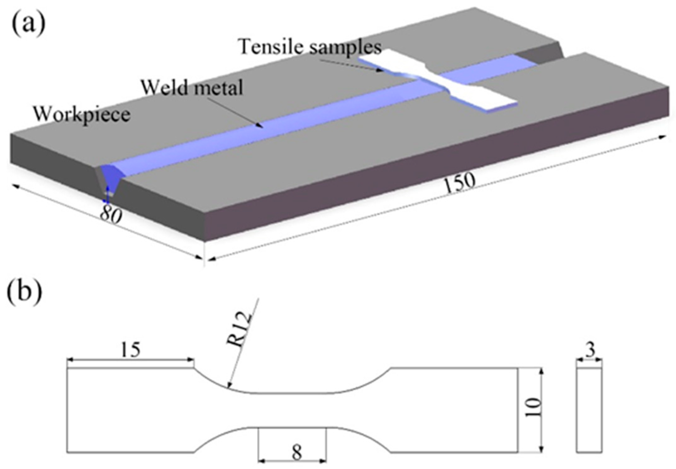
2. Experimental Materials and Procedures

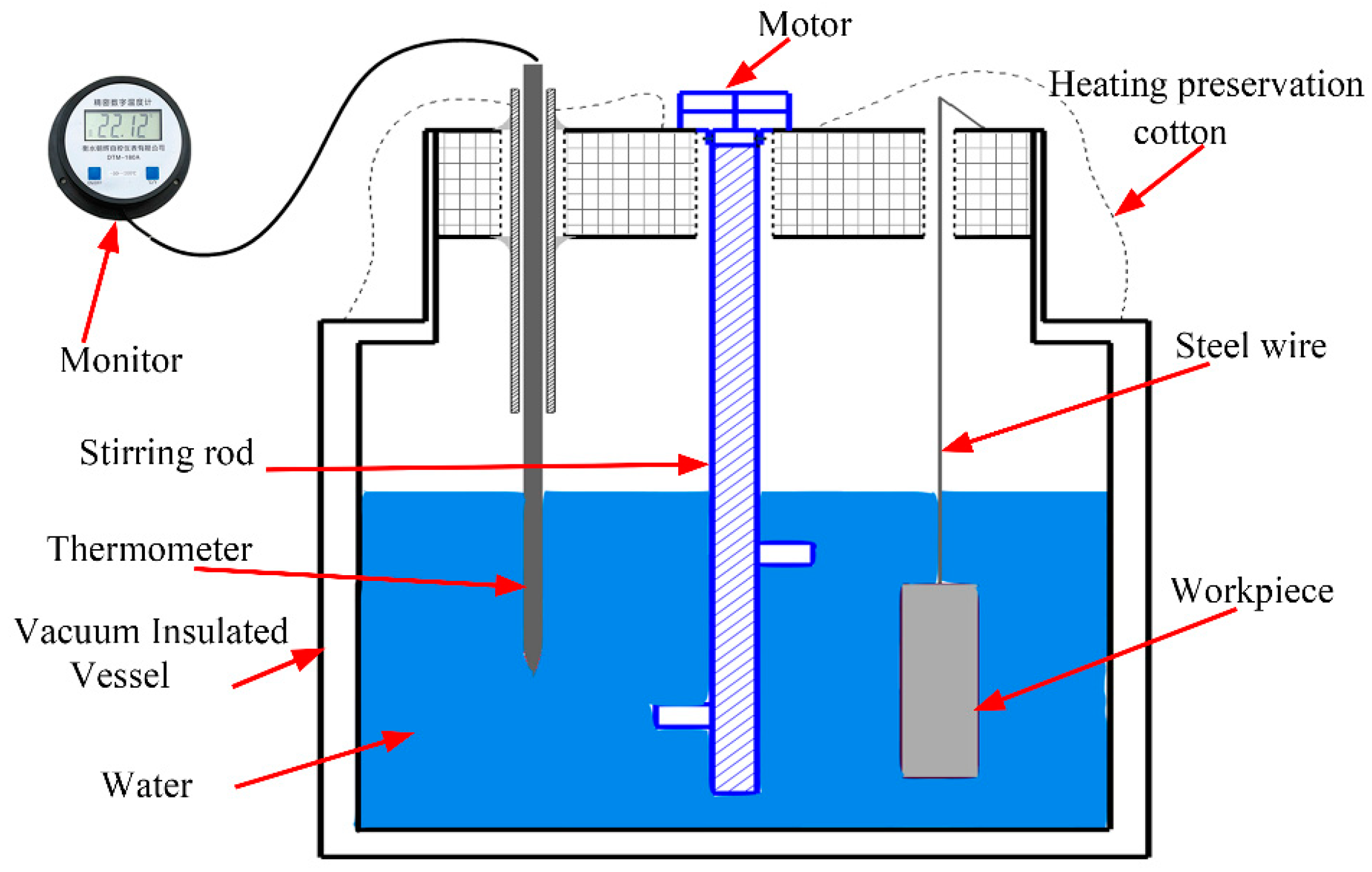
2.1. Underwater Wet Welding Process

Underwater wet self-shielded flux-cored arc welding experiments were carried out automatically at a depth of 0.5 m in a flat position. Groove welds were made to investigate the effect of Al+Fe2O3 on the microstructure and mechanical properties of underwater wet-welded joints. Figure 1 depicts a schematic diagram of the underwater wet welding system, which consists of a traveling machine, a water tank, a welding power supply, a wire feeder, and an electrical signal acquisition device. The welding power source was a constant voltage Aotai NBC 630 (Aotai Electric Co., Ltd., Ji’nan, China). During welding, the welding polarity of DCEP was used. The arc voltage was 30 V, the wire feed speed was 4.5 m/min, the welding speed was 1.5 mm/s, and the wire extension was 15 mm.

2.2. Materials

A mild steel, Q235, was selected as the base material, and its dimensions were 200 mm × 80 mm × 8 mm, which was produced by China Baowu Steel Group Co., Ltd. (Shanghai, China). A schematic of the joint to be welded is shown in Figure 2a. A single pass was made to fill the groove successfully. Figure 2b displays the specimen, which was welded using a 60° V-groove with a 4 mm root opening. The filler was a self-shielded flux-cored wire with a TiO2-CaF2 slag system. The steel stripe on the outside was made of H08A low-carbon steel with a thickness of 0.3 mm and a width of 8 mm. To investigate the effect of Al/Fe2O3 thermite on the underwater welding process, six types of wires with varying Al/Fe2O3 contents (0%, 10%, 20%, 30%, 40%, and 50%), added in flux, were fabricated in the lab. The thermite was composed of a stoichiometric combination of aluminum and Fe2O3. The wire was made using 19–20 wt.% flux fill-to-sheath ratios. The diameter of the experimental flux-cored wires was 1.6 mm. Details of the formulation of the wire with different thermite addition are displayed in Table 1. The powder size of TiO2 and Fe2O3 was 80 mesh. The size of CaF2 and the alloy powders was 100 mesh. It should be noted that while the iron powder and thermite content of the wire remained constant at 50%, the density of the flux decreased as the thermite content increased. The filling rate of the flux-cored wire decreased at a certain wire diameter, and the specific measurement results are shown in Table 1.

2.3. Experimental Methods

After the welding, X-ray fluorescence (XRF, Bruker AXS GmbH., Karlsruhe, Germany) was used to analyze the slag composition at various thermite contents. The microstructure of the weld metal was studied using a metallographic microscope (AxioLab.A1, ZEISS, Oberkochen, Germany) and a scanning electron microscope (SEM, JSM 7800F Prime, JEOL, Tokyo, Japan). The amount of oxygen in the weld metal was measured using a TC500 oxygen/nitrogen analyzer (Leco, St. Joseph, MI, USA). The number and composition of the inclusions were determined using a metallographic microscope and a scanning electron microscope. The area fraction of the inclusions was determined using Equation (1). Image-Pro Plus 6.0 image analysis software was used to calculate the number and size of the inclusions in the weld metal, and tensile tests and microhardness tests were used to evaluate its mechanical properties.
S A = i = 1 k ( d i 2 n i ) D 2 N
where SA represents the area fraction of non-metallic inclusions, %; di is the average diameter of the inclusions, μm; ni represents the number of inclusions; D is the diameter of the investigated view field, μm; N is the number of view field, N = 50.
In order to quantitatively measure the amount of heat transferred to the workpiece when welding using thermite-assisted flux-cored wires, a water calorimeter was designed. The test device, shown in Figure 3, consisted of a vacuum-insulated stainless vessel, a high-precision DTM-180A digital thermometer (Kehui Instrument, Tianjin, China), a stirring rod. (Shanghai Chemspec Corporation, Shanghai, China), and a thermosealed plug covered with heat-preserving cotton (Shanghai Chemspec Corporation, Shanghai, China). The DTM-180A precision digital thermometer uses a Class A PT1000 temperature sensor with high precision and high resolution and can, therefore, reflect the true temperature within seconds. A total of 304L stainless steel was used for the inner and outer layers of the vacuum-insulated stainless vessel. A vacuum existed between the two layers, which effectively reduced heat loss.
The heat transferred to the workpiece during the welding process within a certain period of time was calculated. The welding process was carried out in an air environment. In order to reduce the convective heat loss between the workpiece and the air, the welding time was 20 s, the welding speed was 140 mm/min, the welding parameter arc voltage was 26 V, and the wire feed speed was 55 mm/s. The main steps in measuring T2 were as follows: (1) Before welding, we read the initial temperature T1 of the water in the vessel; (2) immediately after welding, we immersed the workpiece in the water within 3 s to reduce heat loss and improve calculation accuracy; (3) we waited for the digital thermometer’s temperature to stabilize before reading T2. To obtain the average value of T2, we repeated steps (1)–(3) at least three times. The energy obtained by the workpiece was then calculated using Equation (2):
q s = c m ( T 2 T 1 )
where qs represents the energy obtained by the workpiece, J; c is the specific heat capacity of the water (4.2 × 10³ J/kg·°C)); m is the weight of the water in the measuring device (kg); T1 is the initial temperature of the water in the vessel; T2 is the finishing temperature of the water in the vessel;
The device shown in Figure 2 was calibrated prior to measurement. The test copper was heated in a muffle furnace, and its heat content was measured using the water calorimeter at a range of temperatures (50–300 °C, with an interval of 25 °C). Theoretical calculations of the heat content were used to verify the measurements made using the calorimeter. The results showed that the heat calculated using the measuring device was lower than that obtained using the theoretical calculation. The difference between values obtained using these two methods ranged from 5% to 8%. Therefore, an average value of 6.5% was used to calibrate the measuring device.

3. Results and Discussion

3.1. Weld Appearances and Slag

The appearance of welds with different thermite contents is shown in Figure 4. For the basic formulation, the weld seam showed wrinkles and depressions. The transition of the weld seam to the base material was not smooth, indicating that the surface quality was poor. The weld ripples became dense and smooth with the addition of Al/Fe2O3, which proved that the welding bead surface quality was improved. Due to the violent reaction of thermite in the flux, some spatter was formed on both sides of the weld seam when the thermite content exceeded 40 wt.%.
As previously mentioned, the hematite contained a certain amount of SiO2 and Al2O3 in addition to Fe2O3. These oxides reduced the exothermic effect of Al/Fe2O3 thermite. Table 2 shows the composition of the slag with different Al/Fe2O3 contents. The slag in the base formulation belonged to the TiO2-CaO-SiO2 slag system. The high proportion of FeO in the slag was a result of the low amount of deoxidizer in the base formulation. When the thermite content increased, the reduction in the formulation was enhanced. The FeO content in the slag then decreased, while the corresponding Al2O3 content increased from 1.52% to 26.3%. The small amount of SiO2 in the hematite was transferred to the slag alongside that in the core, leading to increased SiO2 concentration in the slag. Furthermore, the slag basicity fell from 1.77 to 0.73, indicating an increase in slag oxidation and in the oxygen content of the weld metal.
B.I = [ZrO2 + MgO + 0.4(CaF2 + NiO + FeO + MnO)]/[SiO2 + 0.3 × (Al2O3)]

3.2. Microstructure Characteristics of Welded Joints with Different Thermite Contents

Figure 5 illustrates the microstructure of the weld metal with various thermite contents. The weld metal in the base formulation was composed of block ferrites. The ferrite grains were relatively coarse, with an average diameter of about 80 μm and a large number of black inclusions, as shown in Figure 5a. The block ferrite was categorized as a primary eutectic ferrite, but it was smaller than the grain boundary ferrite. When the thermite content increased to 10%, the grain boundary ferrite and side lath ferrite appeared. The grain boundary ferrite was large and continuous. The side lath ferrite grew from the grain boundary to the grain, whereas the block ferrite was primarily distributed within the grain. The number of massive ferrites was lower than that of the base formulation. The number of grain boundary ferrite in the weld metal kept growing as the thermite percentage approached 20%. The length of the ferrite lath gradually increased, eventually filling the entire grain. At a thermite content of 30%, acicular ferrite began to appear inside the grain, while the content of side lath ferrite and grain boundary ferrite decreased. When the thermite content was increased further to 40% and 50%, the content of side lath ferrite and grain boundary ferrite continued to decrease, while the content of acicular ferrite increased to 11.5% and 19.4%, respectively.
It was clear that the addition of thermite altered the metallurgical behavior of the weld metal. The microstructure of the weld metal was mainly determined by the welding heat input, alloying element content, and oxygen content (the number of oxide inclusions) [22]. The welding heat input required to melt the wire varied with thermite content, as evidenced by the welding current value. The difference in heat input also affected the weld metal microstructure. Conventional metallurgical ingredients, such as Mn, Ni, and Mo, were not included in the formulation for the flux-cored wires. There should be other reasons for this obvious change. It has been predicted that the addition of thermite may lead to an increase in the amount of oxygen in the weld metal. The relevant research indicated that variations in the weld metal’s oxygen content also affected the microstructural features of the weld metal [23,24]. Therefore, in the current study, it was necessary to analyze the changes in the amount and content of inclusions caused by the addition of thermite.
The white spots in Figure 6 represent the distribution of inclusions in weld metal with various thermite contents. These data were collected from typical microstructure images using Image Pro software. The figure shows that the number of inclusions in the underwater wet welds was high. The inclusions were mostly spherical and ellipsoidal, with a few irregular shapes. When thermite was not used, as seen in Figure 6a, the number of inclusions was high, but their diameter was small. Their number and diameter changed dramatically as the thermite level increased. When the thermite content was low, the inclusions were evenly distributed across the field of view, but when the thermite level was greater than 30%, the inclusions exhibited an aggregation phenomenon.
When the thermite content exceeded 40%, as illustrated in Figure 7, a large number of inclusions agglomerated in the weld metal. This agglomeration reduced the bearing capacity of the welded joint. This was because the aluminothermic reactions produced a large amount of Al2O3, which significantly changed the properties of the slag. Slag with a high melting point cannot be quickly separated from the molten pool. Therefore, the excessive addition of thermite was undesirable in the flux. Meanwhile, it was predicted that with an increase in the thermite content, the inclusions would have a tendency to increase in diameter.
Figure 8 depicts the variation in the number and diameter of the inclusions in the weld metal with different thermite contents. With increasing thermite content, the inclusion density and area fraction in the weld metal increased. The inclusion density in the weld metal was only 7.5 × 10³ N/m3 when no thermite was added, and similarly, the volume fraction of the inclusion stayed at a minimum of 1.87 × 10⁻³%. When Al/Fe2O3 thermite was added, the thermite reaction products could not flow out of the melt pool in time due to the faster cooling rate underwater and remained in the melt pool. This resulted in the formation of a large number of oxide inclusions. When the thermite content was less than 30%, the density and area fraction of the inclusions grew at a slower rate of about 191 and 2.33 × 10⁻⁴, respectively. As the thermite content was greater than 30%, these values were about 615 and 9.01 × 10⁻⁴, indicating that the unit mass of thermite produced more inclusions. At the same time, as the thermite content increased, the size of the inclusions increased and then remained relatively stable. The average diameter of the inclusions was about 0.56 mm for the base formulation, reached 0.79 mm when the thermite content was 30%, and tended to stabilize as the thermite content further increased.
Although the size of the inclusions did not increase with thermite concentration, the number of large inclusions did. Figure 9 displays the distribution of different-size inclusions in the weld metal after statistical analysis for each thermite concentration. The figure shows that the majority of the inclusions in the weld metal measured less than 0.6 mm, followed by inclusions measuring 0.6–1 μm, and the fewest inclusions measured more than 3 μm. As a result, the sizes of the inclusions in the underwater wet weld metal with a TiO2-SiO2-CaO slag system were mostly concentrated in the 0–1 μm. These inclusions accounted for more than 80% of the total quantity.
In accordance with the results shown in Figure 6a, inclusions in the weld metal for the basic formulation that were smaller than 1 μm accounted for 97.3%, while inclusions larger than 1 μm accounted for only 2.7%. When 10% thermite was introduced, the percentage of inclusions smaller than 1 μm was 91.7%, and inclusions greater than 1 μm increased to 8.3%. Upon further increasing the thermite concentration to 20% and 30%, inclusions measuring less than 1 μm and more than 1 μm accounted for 80.8%, 19.2%, 79.8%, and 20.2%, respectively. This indicated that the inclusions steadily grew in size as the thermite content increased. The fraction of inclusions with a size of less than 1 μm grew to 83.5% and 88.3% when the thermite content reached 40% and 50%, respectively. This showed that the weld metal inclusions were decreasing in size. However, it should be observed that the number of inclusions larger than 3 μm steadily increased with the addition of thermite. This result suggested that fine inclusions agglomerated and developed into larger inclusions at a high concentration of thermite.
According to the results of the aforementioned investigation, the addition of thermite to the flux core of the wire increased the density and volume fraction of inclusions in the weld metal. Moreover, the addition of thermite affected the composition of inclusions in the weld metal. Table 3 displays the elemental compositions of the inclusions at various thermite contents. When thermite was not introduced, the predominant inclusions in the weld metal were FeO. As the thermite content increased, Fe in the inclusions decreased, while Si and Al increased. It was predicted that the inclusions would undergo a transformation from Fe-O to SiO2-Al2O3. It is thought that the Fe-O in the inclusions was created via the interaction of Fe in the molten pool with oxide components such as SiO2. The flux and hematite were the sources of the SiO2 in the inclusions, and Al2O3 was a byproduct of the thermite process.
The oxygen concentration of the underwater wet welds with different thermite additions also changed dramatically. The oxygen content variations were measured using an oxygen and nitrogen analyzer, and the results are displayed in Figure 10. The basic formulation’s weld metal had an oxygen content of 0.106 wt.%. The oxygen concentration of the weld metal increased as a result of thermite addition. When the thermite content reached 50%, the weld metal’s oxygen content was 0.182 wt.%. The oxygen was mainly in the form of finely dispersed oxide inclusions. The use of thermite increased the amount of oxide inclusions in the weld metal, resulting in an increase in oxygen content. This was consistent with the results in Figure 7 and Figure 8. According to Harrison [24], higher inclusion contents tended to decrease austenite grain size and increase the amounts of polygonal ferrite and secondary side plates because the transformation temperature changed as a result of the interaction of inclusions with austenite grain boundaries. At the same time, the nucleation of fine intragranular ferrite (acicular ferrite) was aided by oxygen inclusions. This could be used to explain the influence of thermite addition on the microstructure of the weld metal, as shown in Figure 7.

3.3. Mechanical Properties of Welded Joints with Different Thermite Contents

Weld metal microstructure varied as the content of thermite increased. These microstructural changes would result in variations in the mechanical performance of the weld metal. Figure 11a depicts the influence of thermite content on the tensile strength of the weld metal. The ultimate tensile strength (UTS) of the weld metal for the base formulation was 413 MPa. When the thermite content was increased to 10% and 20%, the UTS of the weld metal increased to 426 MPa and 434 MPa, respectively. The tensile strength value increased to a maximum of 446 MPa when the thermite content was increased to 30%, exceeding the tensile strength of the parent material Q235 steel. The tensile strength of the weld metal started to decline as the thermite percentage was raised further, and a minimum value of 379 MPa was reached at a thermite content of 50 wt.%. This low UTS was attributed to the agglomeration of inclusions in the weld metal, which reduced the bearing capacity of the welded joint.
It should be noted that some slag particles were present at the bottom of the groove in the welded joint when the thermite percentage was greater than 30%. This was because the concentration of Al2O3 in the slag was too high to float to the upper portion of the molten pool under a fast-cooling rate. Additionally, as shown in Figure 11b, the average hardness value of the weld metal changed regularly with the addition of thermite, and there was a general increasing trend of microhardness. When the thermite was not utilized, the average hardness value of the weld metal was only 161 HV. With an increase in thermite concentration, the average hardness of the weld metal increased. When the thermite content reached 50%, the average hardness value of the weld metal increased by around 15% to 198 HV. The shift in the microstructure from grain boundary ferrite to acicular ferrite and the increased number of inclusions in the weld metal were responsible for the increase in weld metal hardness.
Figure 12 depicts the microscopic fracture morphology of weld metals with various thermite contents. The fracture surface exhibited coarse dimples and river-like patterns in the base formulation. A mixed fracture pattern was obtained for this fracture, indicating low tensile strength under this parameter. When the thermite addition was 30%, the tensile fracture was composed of many equiaxed dimples distributed with spherical inclusions. The dimples under this parameter were smaller in diameter and deeper than those of the base formulation fractures. This was consistent with the higher strength of the weld metal under this parameter. Meanwhile, the weld metal contained a certain percentage of acicular ferrite. The number and diameter of the inclusions were within a suitable range, which aided in improving the weld metal’s plastic deformation capacity during the tensile process and increasing the weld metal’s strength.
The fracture surface contained a certain percentage of coarse dimples when the thermite content was less than 50%, as shown by the fracture morphology in Figure 12c. However, the overall fracture was flat, and the diameter and depth of the coarse dimples were small, resulting in lower tensile strength under this parameter. When the heat input was above 50%, the number of inclusions until an agglomerated slag formed in the weld, as shown in Figure 12d. The presence of unmelted slag with a high melting point on the microfracture surface lowered the joint’s load-carrying capacity. An excessive number of inclusions also increased the stress concentration problem inside the weld metal and produced microcracks, which further reduced the joint strength.

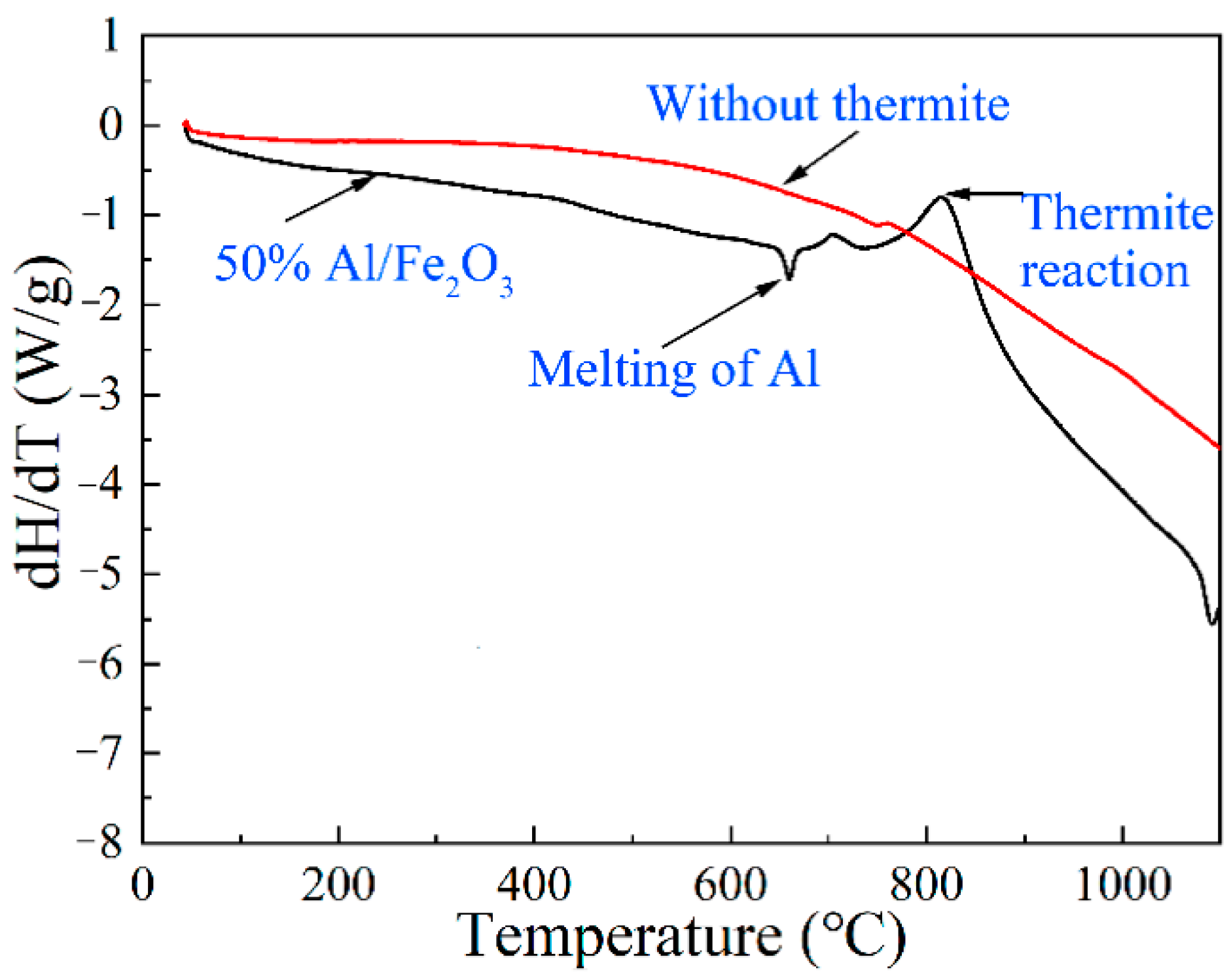
3.4. Effect of Thermite on the Heat Transfer Mechanism of the Welding Process

The exothermic reaction process of thermite is complex due to the multi-component reaction system in the flux-core wire. The chemical heat of thermite is not negligible after it is added to the flux core. An exothermic reaction was carried out in the Al/Fe2O3 system according to Eqations (3)–(5), and the thermite reaction can release more heat during the welding process.
2Al + Fe2O3 → Al2O3 + 2Fe
2Al + Fe3O4 → FeAl2O4 + 2Fe
2Al + 4FeO → FeAl2O4 + 3Fe
We used differential thermal analysis (DSC) tests with multi-component flux, without and with 50% thermite, to determine the exothermic reaction’s onset temperature. The results are depicted in Figure 13. No exothermic peaks were observed in the DSC curves when no thermite was present. The graphs showed obvious heat absorption peaks (at the melting point of Al) and exothermic peaks (the thermite reaction) when thermite was added to the flux, indicating that thermite had a thermogenic effect. It should be noted that the core contained gas-forming, slag-forming, and arc-stabilizing components, which were in direct contact with the Al/Fe2O3 system. For example, Al in the flux may react with the slag-forming component TiO2, and Mn may also react with Fe2O3. The beneficial effect of the Al/Fe2O3 exothermic reaction will be restricted by these reactions.
To further investigate the mechanism of thermite’s effect on the thermal process of welding, the heat device shown in Figure 3 was used to evaluate the thermal efficiency of the welding process in the air environment. Table 4 displays the related parameters required to calculate heat during the welding process. The calculated energy of the welding arc, the energy obtained by the workpiece, the energy of the exothermic reaction, and the energy needed to melt the flux-cored wire are shown in Table 5. The equations for calculating heat are shown below.
qw = U × I × t
where U is the average arc voltage, I is the average welding current obtained from LabVIEW software (2021 SP1, National Instruments Corporation, Austin, TX, USA), and t is 20 s.
q c = i = 1 i = k V f K m M i e q i e
where Mie is the ratio of the thermite in the flux, qie is the amount of heat per unit mass of Al/Fe2O3 thermite (3.977 kJ/g), Km is the flux/sheath ratio (see Table 1), and Vf is the wire feed speed (55 mm/s).
q f = i = 1 i = k ( N i , m V f K i ) 298 T i , t r C p 1 d T + Δ H i , t r + T i , t r T i , m C p 2 d T + Δ H i , m + T i , m T i , B C p 3 d T + Δ H i , B + T i , B T 1 C p 4 d T
where Nim is the mass per unit length of wire; Ki is the proportion of i-th component in the flux; Cp1, Cp2, Cp3, and Cp4 are the molar heat capacities of i-th component in the low-temperature solid, high-temperature solid, liquid, and gaseous states; Ti,tr, Ti,m, and Ti,B are the phase transformation point, melting point, and boiling point of i-th component in the flux; ∆Hi,tr, ∆Hi,m and ∆Hi,B are the enthalpy of phase transformation, enthalpy of melting and enthalpy of vaporization of the i-th component in the flux. The molar heat capacities, enthalpy, and phase transformation temperatures were referenced from the book “Thermochemical properties of inorganic substances” [25].
As shown in Table 4, thermite additions had a considerable impact on the welding arc’s heat input, the energy obtained by the workpiece, and the energy produced by the thermite reaction. Thermite altered the melting behavior of the flux-cored wire, as well as the energy required to melt the wire, influencing the welding current and arc heat input during the welding process. The arc energy input displayed a trend of growing and then dropping as the thermite content increased. The flux-cored wire with the addition of thermite had a higher arc heat input than that of the wire without thermite. The arc energy input remained high when the thermite content was between 10% and 30%.
The workpiece’s measured heat input displayed a similar pattern of fluctuation. Interestingly, the energy input obtained by the workpiece did not peak, even though the wire with 10% thermite addition had the maximum arc energy input. This could be because the high welding arc energy input improved heat dispersion into the workpiece’s surroundings, which decreased the heat it received. The theoretical chemical heat generated by the thermite reaction increased with thermite addition. The maximum chemical heat produced by thermite accounted for around 5.5% of the total arc energy input. It should be noted that the energy input required to melt the wire tended to increase with thermite concentration. This indicated that the addition of Al/Fe2O3 increased the heat required to melt the wire, which proportionately raised the welding arc energy input.
Table 5 demonstrates how thermite affected the thermal efficiency of the welding process in the air. The addition of thermite was proven to enhance the thermal efficiency of the welding process, but the benefit was minimal. When the thermite level reached 50%, the thermal efficiency of the welding arc increased by approximately 3.3%. There was a significant difference between underwater wet welding and onshore welding. The heat and mass transfer processes varied significantly in the two-welding environment. Therefore, a theoretical analysis was carried out to clarify the effect of thermite addition on the cooling rate of welded joints. Cooling time from 800 °C to 500 °C (Δt8/5, s) was determined using the method proposed by Suga [26], as shown in Equations (9) and (10)
R c = 6.25 × 10 5 × Q 0.95 × t 0.17
t 8 / 5 = 455 × R c 1.09
where Q is heat input (J/cm) during the underwater wet welding process, t is the plate thickness (t = 8 mm), and Rc is the cooling rate (◦/s) at the plate thickness t.
Q t Q w + Q c
where Qt is the total heat input in thermite-assisted underwater wet welding process (W), Qw is the heat input from the welding arc, which can be determined by arc voltage (V) and welding current during the underwater wet welding process, qc is chemical heat generated by the thermite reaction during underwater wet welding process (W).
According to the above Equations (9)–(11), the cooling rate of the heat-affected zone with different thermite contents was calculated, as shown in Table 6. Δ*t8/5 in Table 6. represented the cooling time calculated by the welding arc heat input Qw and Δt8/5 represented the cooling calculated by total heat input Q. The cooling time of the welded joint was proportional to the arc input power. When the thermite was introduced into the flux-cored wire, the chemical heat from the thermite reaction increased the total heat input of the welding process. The cooling time of underwater wet welded joints was then increased. This was important for underwater wet welding because it reduced the quenching tendency of low-alloy high-strength steel.
As previously indicated, this above result cannot imply that the addition of Al/Fe2O3 did not considerably improve the welding process. The use of thermite increased underwater wet welding arc stability and promoted metal droplet transfer. Moreover, as demonstrated in Table 4, the maximum chemical heat produced by the exothermic reaction accounted for 7% of the heat obtained by the workpiece. The Al/Fe2O3-type thermite, with a heat yield per unit mass of 3.977kJ/g, was the most highly ranked among several types of thermites. Al/Fe2O3 thermite’s inability to enhance the thermal efficiency of the welding arc may be due to the following. The flux/sheath ratio of the self-shielded flux-cored wire decreased with increasing the content of the thermite, which reduced the content of thermite in the wire. Thermite should have an appropriate density, good fluidity, and a high heat yield in order to enhance the chemical heat per unit length of wire. In this investigation, hematite was typically used instead of pure Fe2O3. This was due to Fe2O3’s low fluidity, which made the preparation of the flux-cored wire problematic. Meanwhile, the theoretical maximum iron concentration of the hematite was 70%. Numerous complicated compounds, such as Al2O3 and SiO2, are also found in hematite, which also reduces the chemical heat generated by the thermite. Thus, future research on thermite-aided underwater wet welding should aim to optimize and choose the type of thermite.

4. Conclusions

The influence of Al/Fe2O3 thermite on electrical dependency, microstructural changes, and mechanical characteristics during the underwater wet FCAW process was examined in this article. The main conclusions are as follows:
  • The addition of the exothermic flux improved the underwater wet weld’s appearance. The FeO content in the slag decreased, and the Al2O3 content increased with increasing thermite content. The slag’s basicity fell from 1.77 to 0.73 because of the formation of Al2O3.
  • Al/Fe2O3 thermite addition increased the inclusion density and area fraction in the underwater wet weld metal. The excessive addition of Al/Fe2O3 thermite led to agglomerated inclusions in the weld metal. The inclusion types changed from Fe-O to SiO2-Al2O3 mixtures.
  • An obvious change in microstructure was observed due to the addition of thermite caused by the de-oxidation products of the thermite process. The ultimate tensile strength first increased and then declined with the addition of thermite. A maximum of 446 MPa was obtained with a thermite percentage of 30 wt.%.
  • The addition of Al/Fe2O3 thermite to flux-cored wire slightly enhanced the thermal efficiency of the welding process. The maximum chemical heat produced by the exothermic reaction accounted for 7% of the heat obtained by the workpiece. Future research on thermite-aided underwater wet welding should aim to develop a new type of thermite and improve the efficiency of the underwater wet welding process.

Author Contributions

J.W. (Jibo Wang): writing—original draft and funding acquisition; C.H.: data curation and formal analysis; H.L.: conceptualization, funding acquisition, and supervision; Z.W. and K.H.: data curation, methodology, validation; D.L.: conceptualization, investigation, writing—review and editing; J.W. (Jianfeng Wang): formal analysis, writing—review and editing, conceptualization; Q.Z.: investigation, resources, validation. All authors have read and agreed to the published version of the manuscript.

Funding

This research and APC were funded by the National Natural Science Foundation of China, grant number 51905225, the Natural Science Foundation of Fujian Province, grant number 2020J05196, and the State Key Laboratory of Advanced Welding and Joining, grant number AWJ-21M09 and AWJ-23M01, and Fujian Provincial Key Laboratory of Welding Quality Intelligent Evaluation, grant number KF-202101 and the Postgraduate Research and Practice Innovation Program of Jiangsu Province (grant nos. KYCX22_3637).

Institutional Review Board Statement

Not applicable.

Informed Consent Statement

Not applicable.

Data Availability Statement

The raw data generated during the present study are available from the corresponding author upon reasonable request.

Conflicts of Interest

The authors declare that they have no known competing financial interest or personal relationship that could have appeared to influence the work reported in this paper.

References

  1. Omajene, J.E.; Martikainen, J.; Kah, P.; Pirinen, M. Fundamental difficulties associated with underwater wet welding. Int. J. Eng. Res. Appl. 2014, 4, 26–31. [Google Scholar]
  2. Fydrych, D.; Łabanowski, J.; Rogalski, G.; Haras, J.; Tomków, J.; Świerczyńska, A.; Jakóbczak, P.; Kostro, Ł. Weldability of S500MC steel in underwater conditions. Adv. Mater. Sci. 2014, 14, 37–45. [Google Scholar] [CrossRef]
  3. Wang, J.; Sun, Q.; Hou, S.; Zhang, T.; Jin, P.; Feng, J. Dynamic control of current and voltage waveforms and droplet transfer for ultrasonic-wave-assisted underwater wet welding. Mater. Des. 2019, 181, 108051. [Google Scholar] [CrossRef]
  4. Liu, S.; Ji, H.; Zhao, W.; Hu, C.; Wang, J.; Li, H.; Wang, J.; Lei, Y. Evaluation of Arc Signals, Microstructure and Mechanical Properties in Ultrasonic-Frequency Pulse Underwater Wet Welding Process with Q345 Steel. Metals 2022, 12, 2119. [Google Scholar] [CrossRef]
  5. Wang, J.; Sun, Q.; Pan, Z.; Yang, J.; Feng, J. Effects of welding speed on bubble dynamics and process stability in mechanical constraint-assisted underwater wet welding of steel sheets. J. Mater. Process. Technol. 2019, 264, 389–401. [Google Scholar] [CrossRef]
  6. Tomków, J.; Landowski, M.; Fydrych, D.; Rogalski, G. Underwater wet welding of S1300 ultra-high strength steel. Mar. Struct. 2022, 81, 103120. [Google Scholar] [CrossRef]
  7. Brätz, O.; Klett, J.; Wolf, T.; Henkel, K.M.; Maier, H.J.; Hassel, T. Induction Heating in Underwater Wet Welding—Thermal Input, Microstructure and Diffusible Hydrogen Content. Materials 2022, 15, 1417. [Google Scholar] [CrossRef]
  8. Guo, N.; Zhang, X.; Fu, Y.; Luo, W.; Chen, H.; He, J.L. A novel strategy to prevent hydrogen charging via spontaneously molten-slag-covering droplet transfer mode in underwater wet FCAW. Mater. Des. 2023, 226, 111636. [Google Scholar] [CrossRef]
  9. Świerczyńska, A.; Fydrych, D.; Rogalski, G. Diffusible hydrogen management in underwater wet self-shielded flux cored arc welding. Int. J. Hydrog. Energy 2017, 42, 24532–24540. [Google Scholar] [CrossRef]
  10. Chen, H.; Guo, N.; Xu, K.; Xu, C.; Zhou, L.; Wang, G. In-situ observations of melt degassing and hydrogen removal enhanced by ultrasonics in underwater wet welding. Mater. Des. 2020, 188, 108482. [Google Scholar] [CrossRef]
  11. Pessoa, E.C.P.; Society, A.W.; Liu, S. The state of the art of underwater wet welding practice: Part 2. Weld. J. 2021, 100, 171–182. [Google Scholar] [CrossRef]
  12. Ma, Q.; Li, H.; Liu, S.; Liu, D.; Wang, P.; Zhu, Q.; Lei, Y. Comparative Evaluation of Self-Shielded Flux-Cored Wires Designed for High Strength Low Alloy Steel in Underwater Wet Welding: Arc Stability, Slag Characteristics, and Joints’ Quality. J. Mater. Eng. Perform. 2022, 31, 5231–5244. [Google Scholar] [CrossRef]
  13. Zhang, X.; Guo, N.; Xu, C.; Du, Y.; Chen, B.; Feng, J. Influence of CaF2 on microstructural characteristics and mechanical properties of 304 stainless steel underwater wet welding using flux-cored wire. J. Manuf. Process. 2019, 45, 138–146. [Google Scholar] [CrossRef]
  14. Allen, J.W.; Olson, D.L.; Frost, R.H. Exothermically assisted shielded metal arc welding. Weld. J. 1998, 77, 277. [Google Scholar]
  15. Malene, S.H.; Park, Y.D.; Olson, D.L. Response of exothermic additions to the flux cored arc welding electrode-Part 1 Effectiveness of exothermically reacting magnesium-type flux additions was investigated with the flux cored arc welding process. Weld. J. 2007, 86. [Google Scholar]
  16. Li, H.L.; Liu, D.; Guo, N.; Chen, H.; Du, Y.P.; Feng, J.C. The effect of alumino-thermic addition on underwater wet welding process stability. J. Mater. Process. Technol. 2017, 245, 149–156. [Google Scholar] [CrossRef]
  17. Pessoa, E.C.; Bracarense, A.Q.; Liu, S. Exothermic additions in a tubular covered electrode and oxidizing reactions influence on underwater wet welding. In Proceedings of the ASME 2007 26th International Conference on Offshore Mechanics and Arctic Engineering, San Diego, CA, USA, 10–15 June 2007; Volume 42703, pp. 259–268. [Google Scholar]
  18. Murzin, V.V.; Russo, V.L. Manual underwater welding structures of steel with higher strength. Weld. Int. 1994, 8, 43–46. [Google Scholar] [CrossRef]
  19. Kumar, A.; Singh, K. Development of exothermic flux for enhanced penetration in submerged arc welding. J. Adv. Manuf. Syst. 2020, 19, 131–146. [Google Scholar] [CrossRef]
  20. Trembach, B.; Grin, A.; Subbotina, V.; Vynar, V.; Knyazev, S.; Zakiev, V.; Kabatskyi, O. Effect of exothermic addition (CuO-Al) on the structure, mechanical properties and abrasive wear resistance of the deposited metal during self-shielded flux-cored arc welding. Tribol. Ind. 2021, 43, 452. [Google Scholar] [CrossRef]
  21. Trembach, B.; Balenko, O.; Davydov, V.; Brechko, V.; Trembach, I.; Kabatskyi, O. Prediction the Melting Characteristics of Self-Shielded Flux Cored arc Welding (FCAW-S) with Exothermic Addition (CuO-Al). In Proceedings of the 2022 IEEE 4th International Conference on Modern Electrical and Energy System (MEES), Kremenchuk, Ukraine, 20–23 October 2022; pp. 1–6. [Google Scholar]
  22. Abson, D.J.; Pargeter, R.J. Factors influencing as-deposited strength, microstructure, and toughness of manual metal arc welds suitable for C-Mn steel fabrications. Int. Met. Rev. 1986, 31, 141–196. [Google Scholar] [CrossRef]
  23. Ferrante, M.; Farrar, R.A. The role of oxygen rich inclusions in determining the microstructure of weld metal deposits. J. Mater. Sci. 1982, 17, 3293–3298. [Google Scholar] [CrossRef]
  24. Harrison, P.L.; Farrar, R.A. Influence of oxygen-rich inclusions on the γ→ α phase transformation in high-strength low-alloy (HSLA) steel weld metals. J. Mater. Sci. 1981, 16, 2218–2226. [Google Scholar] [CrossRef]
  25. Barin, I.; Knacke, O.; Kubaschewski, O. Thermochemical Properties of Inorganic Substances: Supplement; Springer Science & Business Media: Berlin/Heidelberg, Germany, 2013. [Google Scholar]
  26. Yasuo, S. The effect of cooling rate on mechanical properties of underwater wet welds in gravity arc welding. Trans. Jpn. Weld. Soc. 1990, 21, 144–149. [Google Scholar]
Figure 1. Schematic diagram of underwater wet welding system.
Metals 13 00831 g001
Figure 2. Schematic images of the joint (mm): (a) schematic of the joint assembly, (b) schematic of the tensile samples, unit: mm.
Metals 13 00831 g002
Figure 3. Schematic diagram of the designed water calorimeter.
Metals 13 00831 g003
Figure 4. Appearances of underwater wet welds with different thermite content: (a) 0, (b) 10%, (c) 20%, (d) 30%, (e) 40%, (f) 50%.
Metals 13 00831 g004
Figure 5. Microstructure characteristics of weld metal wet different thermite content. (a) 0%, (b) 10%, (c) 20%, (d) 30%, (e) 40%, (f) 50%.
Metals 13 00831 g005
Figure 6. Distribution of inclusions in underwater wet weld metal with different thermite contents. (a) 0%, (b) 10%, (c) 20%, (d) 30%, (e) 40%, (f) 50%.
Metals 13 00831 g006
Figure 7. Aggregation inclusions in the weld metal upon 50 wt.% thermite addition.
Metals 13 00831 g007
Figure 8. Effect of thermite content on the number and diameter of inclusions in the weld metal.
Metals 13 00831 g008
Figure 9. Size distribution of inclusions in weld metal under different thermite conditions.
Metals 13 00831 g009
Figure 10. Effects of the thermite content on the oxygen content of the weld metal.
Metals 13 00831 g010
Figure 11. Variation in mechanical performances of the weld metal under different thermite contents (a) tensile strength, (b) microhardness.
Metals 13 00831 g011
Figure 12. The effects of thermite additions on tensile fracture morphology. (a) 0%, (b) 30%, (c) 40%, (d) 50%.
Metals 13 00831 g012
Figure 13. Differential thermal analysis results of different core components.
Metals 13 00831 g013
Table 1. Formulation of the flux-cored wire with different thermite additions (wt.%).
FormulationTiO2CaF2LiFSiO2MgOTiFeAl/Fe2O3 *Flux/Sheath Ratio
12416224250030.1
224162242401026.1
324162242302022.0
424162242203018.5
524162242104017.2
62416224205015.6
* The Fe2O3 in the formulation was hematite powder with 65% iron content.
Table 2. The compositions of slag (wt.%).
FormulationFeOTiO2CaOSiO2Al2O3MgOZrO2CaF2Slag Basicity
133.747.718.26.931.525.40.784.11.77
22346.818.58.398.46.50.774.81.43
318.843.217.810.914.36.60.744.31.18
417.639.815.713.418.85.90.654.10.97
512.138.416.415.823.66.10.634.50.84
613.433.214.819.726.35.70.584.70.73
Table 3. Element composition of slag in Figure 5 (at.%).
FeTiSiOMnAl
149.05-0.4550.50--
227.882.145.7257.943.982.34
317.153.157.2862.44.175.85
415.722.688.1460.812.849.81
514.332.4610.2756.481.9814.48
67.223.148.4456.752.2822.17
Table 4. The related parameters required to calculate the heat input of the welding process.
U (V)I (A)Mie (%)Nim (g/mm)
126.22143.7800.7426
226.31151.03100.7426
326.27146.65200.7422
426.38146.64300.7515
526.50143.26400.7525
626.52142.67500.7740
Table 5. The heat input and consumption of the exothermic wire.
qw (J)qs (J)qc (W)qf (W)Arc Efficiency (%)qc/qw (%)qc/qs (%)
175,39855,2010118973.200
279,53257,64268119872.51.72.4
377,04858,021114120975.33.03.9
477,36757,483144122674.33.75.0
575,92757,423184123975.64.86.4
675,78857,954208127676.55.57.2
Table 6. The calculated cooling time from 800 °C to 500 °C of underwater wet welded joints with different thermite contents.
TestU (V)I (A)Qc (W)Qw (W)Q (W)Δ*t8/5Δ t8/5
1205.3529.6506088.636088.638.818.81
2206.1129.5592.726090.556183.288.828.96
3213.7329.50155.456305.046460.499.149.37
4215.9029.37196.366340.986537.359.199.49
5210.5529.33250.916175.436426.348.949.32
6211.1729.27283.646180.956464.588.959.38
Disclaimer/Publisher’s Note: The statements, opinions and data contained in all publications are solely those of the individual author(s) and contributor(s) and not of MDPI and/or the editor(s). MDPI and/or the editor(s) disclaim responsibility for any injury to people or property resulting from any ideas, methods, instructions or products referred to in the content.

