
The Synthesis of Lead-Bearing Jarosite and Its Occurrence Characteristic and Leaching Toxicity Evaluation
1
School of Metallurgy and Environment, Central South University, Changsha 410083, China
2
Changsha Research Institute of Mining and Metallurgy Co., Ltd., Changsha 410012, China
3
Chinese National Engineering Research Center for Control & Treatment of Heavy Metal Pollution, Changsha 410083, China
*
Author to whom correspondence should be addressed.
Metals 2023, 13(5), 941; https://doi.org/10.3390/met13050941
Submission received: 26 April 2023
/
Revised: 6 May 2023
/
Accepted: 10 May 2023
/
Published: 12 May 2023
(This article belongs to the Special Issue Comprehensive Utilization of Metallurgical Resources and Environmental Protection)
Abstract
:Lead is the main toxic factor in jarosite residue. It is important to study the release behavior of lead from simulated lead-bearing jarosite (SLBJ) for predicting the stability of jarosite residue and its secondary pollution to the environment. To identify the technical issues and limitations associated with its safe disposal, a comprehensive analysis of the chemical, structural, and morphological characteristics of SLBJ was conducted using various detection techniques including XRF, XRD, SEM-EDS, FTIR, XPS, etc. The environmental stability of SLBJ was assessed through the toxicity characteristic leaching procedure (TCLP), Chinese standard leaching tests (CSLT), and a long-term leaching experiment (LTLE). Phase composition analysis revealed that the primary components of SLBJ are sodium jarosite and lead sulfate. TCLP and CSLT results indicated that lead content surpassed the toxicity identification standard limit by more than 47 times. Furthermore, LTLE indicated that the lead concentration surpassed the standard limit about 15 times after prolonged contact time. This study is of great significance for predicting the stability of jarosite residue and its secondary pollution to the environment.
1. Introduction
The jarosite process, commonly employed in zinc hydrometallurgy, has emerged as a prevalent technique for iron removal. This process offers notable advantages such as operational simplicity, cost-effectiveness, and effective slag filtration performance. Yet at the same time, it also produces a huge amount of jarosite residue which is harmful to the environment [1,2,3]. At present, jarosite residue has been listed as hazardous waste by many countries [4]. The existing research on jarosite residue has predominantly focused on the coprecipitation behavior of heavy metals within jarosite residue; however, there is still a lack of comprehensive understanding regarding the chemical forms and long-term stability of heavy metals in jarosite residue. In fact, the speciation distribution and environmental pollution characteristics of heavy metals, including leaching toxicity, are influenced not only by their content but also by their existing state and the mineral phase structure of jarosite residue. Recent studies have revealed that zinc and lead are the predominant toxic and harmful elements in jarosite residue [5], with zinc primarily existing in the form of zinc ferrite in zinc calcine, which can be replaced by carbonate to prevent the formation of insoluble zinc ferrite and mitigate pollution [6,7]. As lead represents the most significant toxic factor in jarosite residue, it is crucial to investigate the behavior of lead during the jarosite precipitation process and its environmental characteristics, which can reveal that its behavior can bring a substantial impact to the environment.
Numerous researchers have investigated the coprecipitation of various metals and jarosite, such as some prominent studies conducted by Dutrizac et al. [8,9,10,11,12,13,14,15,16,17,18,19,20]. In these studies, a range of metals, including Pb, Ag, Cu, Zn, Cd, Cr, As, In, Au, Tl, Rb, RE, etc., were synthesized and the formation conditions and influencing factors of the coprecipitation process were extensively explored. Additionally, Getskin et al. [21] investigated the behavior of divalent metal ions during coprecipitation and concluded that the coprecipitation with jarosite resulted from the substitution of these ions for Fe3+ in the jarosite lattice to form A(Fe3−xMx2+)(SO4)2(OH)6. The coprecipitation form of lead with jarosite is the most complex; the adsorption of Pb in the presence of iron minerals is the first pathway for coexistence [22]. Numerous studies have reported that Pb ions can strongly bind to iron minerals by forming inner-sphere surface complexes [23,24]. Recently, Lu et al. [25] discovered that Pb ions can penetrate the loose, porous structure of hematite nanoparticles through adsorption. While Pb adsorption on jarosite is possible, its incorporation is typically more prevalent under certain conditions [26,27]. Pb ions can be incorporated at the K-site in jarosite, forming plumbojarosite (Pb0.5Fe3(SO4)2(OH)6), which represents the second pathway. During the formation of plumbojarosite, the formation of PbSO4 is often inevitable, especially in the zinc hydrometallurgy process. Several studies have found that Pb in jarosite residues is primarily in the form of PbSO4 and is largely embedded by jarosite [28]. Thus, embedding PbSO4 in the jarosite matrix during fast coprecipitation is also an important, potentially dominant pathway. These multiple mechanisms for the coexistence of Pb and jarosite contribute to the complex behaviors of Pb during jarosite transformation under various conditions [29]. The coexistence of lead and jarosite via multiple mechanisms makes it difficult to separate and recover the lead.
The pollution characteristics of lead in jarosite residue are influenced by its occurrence state. Lead in the form of a crystal lattice typically has low environmental activity, whereas the adsorbed lead is more detrimental to the environment. Furthermore, the alteration of the mineral phase structure of iron also affects the environmental activity of lead. Environmental factors such as redox conditions, solution pH value, and microorganisms can cause the dissolution or recrystallization of the jarosite phase, thereby modifying its surface properties and crystal structure [30,31]. Consequently, the coprecipitated lead can be released or refixed, influencing the migration and environmental behavior of lead. Wu et al. [32] found that after the addition of 10 mM Fe2+ to the polymetal-containing jarosite at pH7, the release of Zn, Pb, and Cu in the liquid phase increased significantly and the jarosite was converted into goethite or magnetite. Smeaton et al. [33] inoculated an iron-reducing bacteria in the lead-containing jarosite, and the jarosite structure was destroyed after 336 h of incubation. It was found that 12.4% of the iron in the mineral was released into the solution in the form of ferrous iron, and the lead was transformed into cerussite, redistributed, and fixed in the slag. Therefore, it is necessary not only to control lead concentration but also to regulate the occurrence state and phase of lead for ensuring environmental stability.
The jarosite residue generated by zinc hydrometallurgy often possesses a complicated structure and multiple impurities, leading to the difficulty in analysis of lead migration and environmental behavior within the residue. To address this challenge, a kind of simulated lead jarosite residue needs to be synthesized for examining its lead release behavior. A chemical synthesis technique and iron removal conditions of the industrial jarosite method/process were employed in this study to synthesize the simulated lead-containing jarosite by modifying the neutralizer from zinc calcine to NaOH solution.
Characterization and analysis of the synthesized lead-containing jarosite were conducted alongside an investigation of the leaching toxicity of lead. These investigations are crucial in predicting the stability of lead-containing jarosite residue and the subsequent pollution risks to the environment. As such, this study offers a theoretical basis for the reduction of source pollution from jarosite residue by regulating jarosite precipitation in the zinc hydrometallurgical industry.
2. Materials and Methods
2.1. Materials
Ferric sulfate (Fe2(SO4)3·xH2O), sodium sulfate (Na2SO4), lead acetate (Pb(CH3COO)2), sodium hydroxide (NaOH), and sulfuric acid (H2SO4) were purchased from Sinopharm Chemical Reagent Co., Ltd., (Beijing, China) and all the chemicals were of analytical-reagent grade. All solutions were prepared using ultrapure water (18 MΩ·cm).
2.2. Synthesis of Simulated Jarosite
The simulated lead-bearing jarosite was synthesized using a 1 L solution containing 0.25 mol/L Fe2(SO4)3·xH2O and 0.06 mol/L Na2SO4 by constantly stirring at 600 r/min at 95 °C [6,22]. The pH was adjusted to 1.0 with a 7.0 mol/L NaOH solution, followed by the gradual addition of 100 mL of 0.3 mol/L Pb(CH3COO)2 solution at a rate of 50 mL/h and stirring. Meanwhile, NaOH solution was added until the pH was adjusted to 2.0. The precipitates were further stirred for 3 h, followed by settling and decantation of the residual supernatant solutions. The same protocol was used to synthesize jarosite with various lead content by controlling the amount of Pb(CH3COO)2 added while maintaining other synthesis conditions constant. Furthermore, the different lead source was tested by replacing Pb(CH3COO)2 with PbSO4 to investigate the effect of lead ions (from Pb(CH3COO)2) and solid lead (from PbSO4) on iron precipitation using the jarosite process, which was conducted to make the synthesized lead-containing jarosite from different lead sources better reflect the actual lead-containing jarosite residues in the industry. After the synthesis, the simulated jarosite was separated from the solution by vacuum filtration, and then washed with ultrapure water (18 MΩ·cm) several times and dried at 80 °C for 24 h.
2.3. Leaching Test
The Toxicity Characteristic Leaching Procedure (TCLP) is a widely used method prescribed by the US Environmental Protection Agency (EPA) to determine the potential environmental risk of solid samples and classify them as hazardous waste or not. In addition, China Identification Standard for Hazardous Wastes (HJ/T 299-2007;HJ/T 300-2007) [34,35], named CSLT-1 and CSLT-2, respectively, were compared with the TCLP method.
The CSLT method is similar to the TCLP method in terms of sample treatment steps, such as grinding, sieving, and weighing. However, the main difference lies in the leaching agent and pH value. The comparison of the two methods was listed in Table 1.
CSLT-1 is designed for leachate from industrial solid waste landfill sites, while CSLT-2 and TCLP use CH3COOH to simulate leaching solutions, accounting for organic acid presence. As for the pH value selected in the three methods, a lot of empirical data were taken for reference. It is widely acknowledged that metals are more likely to form soluble oxides and increase solubility under acidic conditions, which is consistent with the leaching trend of heavy metals in smelting slag.
The CSLT-2 method was taken as an example to briefly describe the following steps. Dried samples (1.00 g) were added to polyethylene extraction bottles along with liquid extractant at a ratio of 20:1. The extraction fluid consisted of a mixture of glacial acetic acid with pH adjusted to 2.64 ± 0.05. The sample was then tumbled for (18 ± 2) h at the rotation speed of 30 r/min and pressure filtered through acid-treated (CH3COOH) 0.45 μm glass fiber filter paper. The eluant was collected and placed in an acid (CH3COOH)-rinsed polyethylene bottle for further analysis.
In order to simulate the long-term leaching effect of jarosite residue under an acid rain environment, a long-term leaching experiment (LTLE) was designed according to ANS (1986) standard [36]. A 30 g residue was used for each test and the leaching agent (deionized water adjusted to pH of 3.00 ± 0.05 with H2SO4, HNO3, and CH3COOH in a mass ratio of 3:1:3) was to simulate acid rain. The leaching process lasted for 20 d with a leaching speed of 1.25 mL/h. The leaching solution was collected every 24 h and filtered through 0.45 μm filter membrane. Then, the content of heavy metals in the filtrate was analyzed to evaluate its long-term stability.
2.4. Analysis
2.4.1. Determination of Elemental Composition
The chemical composition of jarosite residue was detected firstly by XRF (Bruker, model S4-PIONER) and then the main elements such as iron, lead, zinc, copper, silver, sulfur, arsenic, and cadmium were analyzed by AAS or ICP-AES based on XRF results.
The total content of the main elements could be obtained according to the following steps. The air-dried samples were oven-dried at 90 °C for 4 h, then crushed and sieved to be a particle size of 74 μm. After that, the powders were accurately weighed out to 0.2 g and placed in a 20 mL polyethylene tube with 10 mL of 6 mol/L HCl and stand for digestion at room temperature for 24 h. If there is still a small amount of undigested solid powder, it can be manually agitated to accelerate digestion or be further digested by adding HNO3. The solution was diluted with deionized water in 50 mL volumetric flasks and analyzed by AAS or ICP-AES.
2.4.2. Determination of Phase Composition
The mineralogical composition of the samples was determined firstly by X-ray diffraction analysis (XRD, BRUKER, D8 ADVANCE) using Cu Kα radiation with steps of 0.02° at 10°/min in a 2θ range from 5° to 80° under operating conditions of 40 kV and 40 mA. Then, the phase composition of iron, lead, zinc, and copper was investigated using chemical analysis based on XRD results.
During the analysis, one main phase was dissolved in a preprepared specific solvent. The leaching solution was filtered with a vacuum filter after dissolving completely and the filter residue was used for the analysis of another phase in the next stage. Meanwhile, the content of the supernatant was analyzed by AAS or ICP. The chemical phase analysis process of lead is shown in Figure 1 [37].
2.4.3. Others Analysis
The microstructure, surface morphology, and special part chemical composition were observed by scanning electron microscope (JEOL, Tokyo, Japan, JSM-7900F). The same sample was also subjected to the element distribution analysis through X-ray mapping analysis via SEM. The grain morphology and mineralogical surface composition of jarosite residue were examined by XPS (Thermo Fisher Scientific, Waltham, MA, USA, ESCALAB 250Xi) with Al Kα X-ray source in a vacuum of 10−7 Pa. The molecular bonding structure and the phase composition were studied by FTIR (Thermo Fisher Scientific, Waltham, MA, USA, IS50 FT-IR) on KBr pellets in the 4000–400 cm−1 spectral range with 32 scans per spectrum at a resolution of 4 cm−1. The particle size of jarosite residue was analyzed by a laser particle size analyzer (Malvern Panalytical, Malvern, UK, Mastersizer-2000). The specific surface area analysis measurement was determined by a fully automatic nitrogen adsorption-specific surface instrument (BSD Instrument, Beijing, China, 3H-2000A).
3. Results and Discussion
3.1. Chemical Composition
The results of the chemical element analysis of this simulated lead-bearing jarosite, named PJ10, PJ10-P, PJ2, and PJ6, respectively, are shown in Table 2. The results show that the molar ratio of sodium to iron in the simulated jarosite is less than 0.33, which may be attributed to the substitution of lead for part of sodium leading to the formation of Pb-containing jarosite. The Pb content of PJ10 synthesized using Pb(CH3COO)2 as the lead source is consistent with the theoretical value, while the Pb content of PJ10-P synthesized using PbSO4 is lower than the theoretical value. This may be due to the fact that PbSO4 is added in the solid form and the fact that only part of it can participate in the precipitation process of jarosite. The uneven distribution of Pb in PJ10-P resulted in a lower Pb content.
3.2. Phase Composition
Figure 2 shows the XRD spectrum of the formation process of PJ10. It is found that the characteristic diffraction peaks of lead jarosite during different period are the same, mainly including the diffraction peak of sodium jarosite (NaFe3(SO4)2(OH)6, PDF #36-4025), and lead sulfate (PbSO4, PDF #36-1461). The characteristic peaks of sodium jarosite and lead sulfate are enhanced with the extension of time, which indicates that the crystallinity of lead jarosite is higher.
Figure 3 shows the XRD patterns of PJ10 compared with the sodium jarosite (NJ) and lead sulfate (PB). The results show that the diffraction peaks of sodium jarosite (PDF#36-0425) and lead sulfate (PDF#36-1461) in the PJ10 can correspond well to the diffraction peaks of NJ and PB and there is no other miscellaneous peak.
Figure 4 shows the XRD patterns of simulated jarosite with different lead content. The results show that the characteristic diffraction peaks of PbSO4 increase obviously with the increase of lead content, which indicates that most of lead in SLBJ exists in the form of PbSO4. The characteristic diffraction peak of sodium jarosite also increases with the increase of lead content, which indicates that the addition of lead is beneficial to the precipitation of jarosite. It is found that the rate of vitriol precipitation is obviously accelerated after the addition of lead acetate, and the time is shortened by 1/3 compared with that of jarosite synthesis without lead. It is also found that lead sulfate can promote the vitriol precipitation process. Therefore, the addition of lead can promote the jarosite precipitation process and accelerate the precipitation of iron.
The chemical phase analysis of lead was carried out on SLBJ with different lead content for getting more knowledge about the existing forms of lead. The results are shown in Table 3. It is found that lead exists mainly as lead sulfate and lead jarosite (including others). The proportion of lead sulfate is 31.3%, 32.1%, and 34.3%, respectively, in PJ2, PJ6, and PJ10, meanwhile, lead jarosite is 68.5%, 67.7%, and 65.6%, respectively. The lead in the lead-containing jarosite samples, synthesized using the same lead source and synthesis method, mainly exists in the same form. The proportion of the lead sulfate phase ranges from 31% to 35% and slightly increases with increasing lead content, while the proportion of the lead jarosite phase ranges from 65% to 69% and slightly decreases with increasing lead content. The proportion of lead sulfate in PJ10-P increases to 81.3%, which is much higher than others, indicating that the lead phase in SLBJ from different lead sources is different.
3.3. Structural Feature
SEM analysis was carried out for the formation process of PJ10 after different reaction times and the results are shown in Figure 5. It can be seen that coarse jarosite particles are generated at the beginning of the reaction, and small particles of lead sulfate are adsorbed on the surface of the generated jarosite. Lead sulfate adsorbed on the surface is wrapped with jarosite particles growing up, and greatly reduced when the reaction lasts for 180 min. The formed crystal is a smooth octahedron with a particle size of about 5–10 μm. Only a small amount of fine lead sulfate can be seen on the surface, which indicates that most of the lead sulfate adsorbed on the surface is wrapped in the crystal.
The secondary and backscattered electron images of PJ10 are shown in Figure 6, presenting the difference in chemical compositions. It is found that the PJ10 consists of ~10 μm regular octahedral or overlapping darker rhombohedral particles and ~1 μm brighter oval or round grains. BSE analysis shows the major elements of the darker phase are Na, Fe, S, and O, indicating that could be sodium jarosite. Whereas, the brighter particles contain Pb, S, and O, in a molar ratio of 1:0.9:3.9, indicating that the bright white point is mainly lead sulfate. The small lead sulfate particles are widely distributed in the jarosite substrate, making it difficult for lead to be separated from PJ10.
The BSE of SLBJ with different lead content is taken to show the difference in the distribution of lead in Figure 7. The graph depicts a gradual increase in the intensity of bright spots, indicating an increase in the amount of lead sulfate embedded on the surface with an increase in the lead content.
In order to identify the internal morphology and element distribution of PJ10, the samples were cured with triethanolamine-epoxy resin and analyzed by SEM-EDS after slicing, grinding, and polishing, and the results are shown in Figure 8. The presence of three distinct types of particles in PJ10 is revealed. The first type is identified as PbSO4, which is characterized by bright white spots at points 2, 4, 5, and 9, and the main elements present in this type of particle are O, S, and Pb. The second type is identified as jarosite with a darker phase, observed at points 6, 7, 8, 10, and 12, with the predominant elemental composition of O, S, Fe, and Na. The third type is determined to be lead-containing jarosite, observed at points 1, 3, and 11, with main elemental constituents of O, S, Fe, Na, and Pb, and is found to have a scattered distribution of lead, with fine lead-containing particles embedded within the jarosite substrate, bringing challenges to their separation.
Furthermore, Figure 9 displays the SEM of PJ10-P, which was synthesized using lead sulfate as the lead source. Notably, the particles of PJ10-P synthesized with lead sulfate are larger compared to PJ10, with an average size of approximately 20 μm. PJ10-P particles exhibit a spherical morphology composed of numerous overlapping rhombohedra and embedded with a relatively small amount of fine lead sulfate. Importantly, the amount of lead sulfate embedded or adsorbed on the surface of PJ10-P is noticeably lower than that of PJ10. This observation may be attributed to the limited participation and interaction of the solid lead sulfate during the jarosite precipitation process, resulting in reduced lead inclusion or adsorption.
3.4. Molecular Bonding Structure
The infrared spectrum of PJ10 is given in Figure 10, comparing both sodium jarosite (NJ) and lead sulfate (PB) to gain further insight into the structural features of PJ10; data analysis was performed according to the results and relevant manuals [38,39,40]. The spectrum shows that the stretching vibration peak at 3360 cm−1 is attributed to v-OH, while the peak at 1636 cm−1 corresponds to the stretching vibration of HOH caused by water molecule deformation. Additionally, peaks at 1190 cm−1, 1100 cm−1, and 1000 cm−1 are identified as stretching vibration peaks of v3(SO4), indicating the presence of sodium jarosite and a lead sulfate structure. Furthermore, peaks at 629 cm−1 and 597 cm−1 are assigned with v4(SO4) stretching vibrations, consistent with the characteristic peaks of sodium jarosite and lead sulfate. This confirms the existence of jarosite and lead sulfate in PJ10. Moreover, peaks at 473 cm−1 and 507 cm−1 are indicative of the octahedral structure of FeO6, characteristic of jarosite.
Comparatively, PJ10 exhibits a more complex FTIR spectrum compared to NJ. Notably, the characteristic peak of lead sulfate v4(SO4) at 597 cm−1 present in PJ10 suggests the presence of PbSO4 in the structure. Furthermore, fluctuations in characteristic peaks between 400 cm−1 and 480 cm−1 indicate possible changes in the Fe-O structure, possibly due to the substitution of Pb for Fe in the lattice of the Fe-O structure, resulting in the formation of lead jarosite.
3.5. Surface Performance
In order to gain a deeper understanding of the elemental composition and valence state in PJ10, photoelectron spectroscopy was conducted to determine the binding energies of Fe2p, C1s, O1s, S2p, Pb4f, and Zn2p in a sample. The obtained XPS spectrum was analyzed using Avantage software (as shown in Figure 11) and interpreted in conjunction with relevant references [41,42].
The full spectrum (Figure 11f) reveals that the PJ10 predominantly consists of O, Pb, Fe, S, Na, and other elements. Among them, Fe2p, O1s, C1s, S2p, and Pb4f were subjected to peak fitting to determine their valence state and possible chemical forms.
The binding energies of Fe2p3/2 and Fe2p1/2 are determined to be 711.9 eV and 726.1 eV, respectively, both of which are higher than 710 eV, indicating the presence of Fe(III) in the initial minerals. Further peak-splitting analysis of Fe2p3/2 (Figure 11a) reveal characteristic peaks corresponding to Fe(III) and Fe(III)-SO4, with electron binding energies of 713.5 eV, 715.7 eV, and 711.9 eV, respectively. Additionally, a satellite peak of Fe2p is observed at 720.7 eV.
The characteristic peak of Fe(OH)O (Figure 11b) was identified from the peak fitting spectrum of O1s, with an electron binding energy of 513.5 eV. The C1s peak separation result (Figure 11c) shows that carbon bonds are present as C-C, with an electron binding energy of 284.4 eV. S2p peak separation results (Figure 11d) indicate that sulfur bonds are predominantly in the form of SO4, with corresponding electron binding energies of 168.5 eV and 169.7 eV, respectively.
The electron binding energy of Pb4f5/2 is determined to be 143.7 eV, which corresponds to the characteristic peak of PbO2. Peak splitting analysis of Pb4f7/2 (Figure 11e) reveals fitting spectra with characteristic peaks of PbO, PbO2, and PbSO4, corresponding to electron binding energies of 138.8eV, 137.4eV, and 139.4eV, respectively. The characteristic peaks of Pb in PJ10 are found to be similar to those in industrial jarosite residue, suggesting that the synthesized simulated jarosite residue PJ10 is representative in terms of Pb composition.
3.6. Particle Size Features
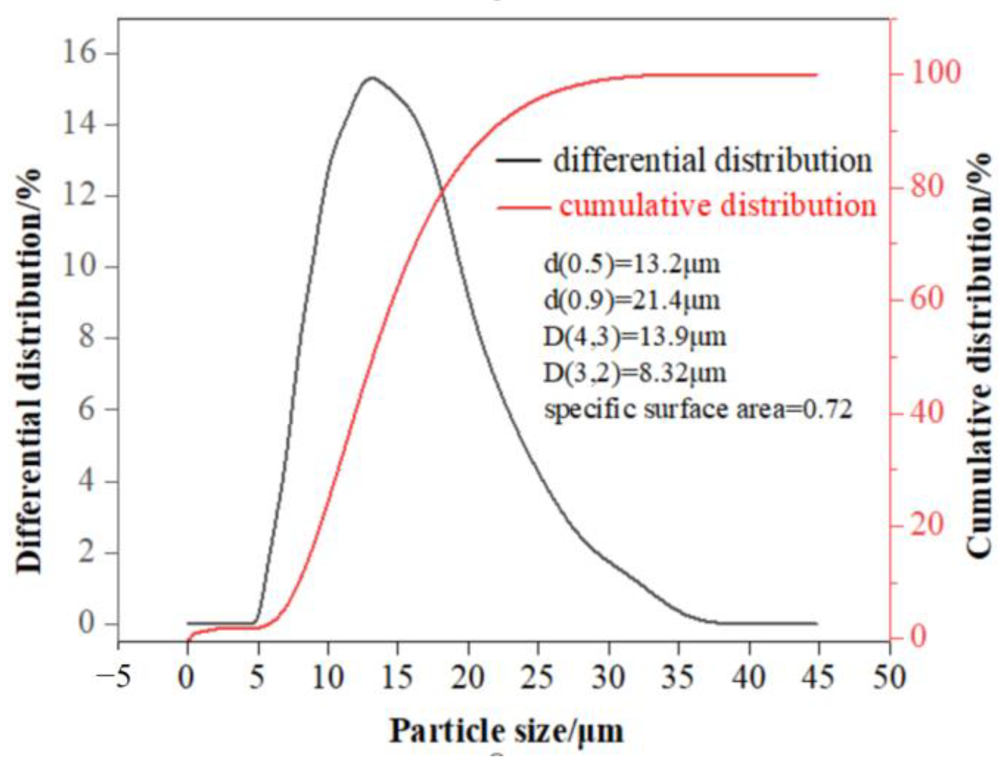
Figure 12 shows a range of the particle size distribution from 0 to 50 μm. It is found that the particles exhibit a small size, with d(0.5) and d(0.9) values of 13.2 μm and 21.4 μm, respectively. The volume average particle size D(4,3) is calculated to be 13.9 μm while the surface area average particle size D(3,2) is determined to be 8.32 μm. Additionally, the specific surface area of PJ10 is measured as 0.72 m2/g. Notably, PJ10 displays larger surface area and volume average particle size values in comparison to NJ, indicating that an addition of lead can result in the increase in the particle size.
3.7. Environmental Stability
The leaching toxicity of Pb in PJ10 was investigated and the results are presented in Table 4. The toxicity was assessed using three different detection methods, showing yielded concentrations were 238 mg/L, 73.9 mg/L, and 246 mg/L, respectively. The TCLP and CSLT-2 methods both utilize CH3COOH as the extractant, which has the capability to dissolve PbSO4 and release more Pb from the residue. In contrast, the CSLT-1 method employs H2SO4 as the extractant, which cannot dissolve PbSO4 and releases less Pb. Since organic acids are commonly present in natural environments, the use of CH3COOH as the extractant can more accurately reflect the toxicity release. Since it has the highest Pb concentration exceeding the standard threshold by 47.7 times, it is classified as hazardous waste.
Long-term stacking of PJ10 in the environment may pose environmental pollution risk due to heavy metal redissolution. Therefore, the results of continuous leaching procedure are shown in Table 5. It is found that the concentration of Pb in the leaching solution was high, ranging from 243 to 186 mg/L during the initial stage of leaching (0–120 h) due to the leaching of Pb embedded on the surface by mixed acid. Subsequently, the lead concentration decreased steadily to a range of 186–87 mg/L with continuous leaching for 120–216 h and the lead remained relatively stable at 70–80 mg/L after 216 h. This could be attributed to the destruction of the PJ10 structure, leading to the migration of internal lead to the surface where it reacted with the extractant. As the reaction approached equilibrium, the concentration of lead in the leaching solution reached a plateau. However, the concentration of lead in the leachate remained significantly high at around 75 mg/L even at equilibrium, which was about 15 times higher than the toxic identification standard threshold of 5 mg/L for lead, indicating that jarosite exhibits high leaching activity and lead is unstable, thus it is categorized as hazardous waste.
4. Conclusions
It can be concluded that the formation process of simulated lead-bearing jarosite involves the nucleation and growth of jarosite particles, with lead sulfate adsorbed on the formed jarosite. The addition of lead is beneficial to the precipitation of jarosite and the source of lead affects its synthesis. The synthesized jarosite consists mainly of sodium jarosite and lead sulfate, with the PbSO4 phase accounting for 31–34% of the total lead. The structural characteristic peaks of sodium jarosite and lead sulfate are present in the synthesized lead jarosite, consistent with the findings obtained from XRD, SEM, FTIR, and XPS analyses. The results indicate that the synthesized lead-bearing jarosite is representative of industrial jarosite residue. However, the leaching toxicity and long-term stability test results reveal that lead-containing jarosite is hazardous waste, with high environmental activity and unstable lead content, which far exceeds the standard lead threshold. Thus, proper disposal of lead-containing jarosite is necessary for preventing adverse environmental and health impacts.
Author Contributions
J.P. and X.Y. conceived and designed the experiments; J.P. and X.Y. analyzed the data; J.P. wrote and edited the paper; X.Y. and H.L. revised the work critically for important intellectual content. Conceptualization, J.P.; methodology, J.P.; software, J.P., L.H. and Z.S.; validation, J.P. All authors have read and agreed to the published version of the manuscript.
Funding
This work was supported by the Major Program Natural Science Foundation of the Hunan Province of China (No. 2021JC0001), the National Natural Science Foundation of China (No. 22276218), and the National Key R and D Program of China (No. 2021YFC2902804 and No. 2022YFC2904603).
Data Availability Statement
The original data used in this study cannot be made publicly available due to privacy and ethical considerations. Additionally, some of the funding projects related to this study are still ongoing and have not yet been concluded. Therefore, the data cannot be released at this time. We assure readers that our conclusions and findings have been reached through rigorous analysis of the available data and robust methodologies. We will reevaluate the possibility of sharing the data once all relevant funding projects have been concluded and all privacy and ethical considerations have been addressed.
Acknowledgments
We gratefully acknowledge many important contributions from the researchers of all the reports cited in our paper.
Conflicts of Interest
The authors declare no conflict of interest.
References
- Ahamed, A.M.; Pons, M.N.; Ricoux, Q.; Issa, S.; Goettmann, F.; Lapicque, F. New pathway for utilization of jarosite, an industrial waste of zinc hydrometallurgy. Miner. Eng. 2021, 170, 107030. [Google Scholar] [CrossRef]
- Kushwaha, P.; Agarwal, M.; Ghosh, A. Value-added products from jarosite hazardous waste: A review. Mater. Today Proc. 2023, 76, 201–205. [Google Scholar] [CrossRef]
- Hoeber, L.; Steinlechner, S. A comprehensive review of processing strategies for iron precipitation residues from zinc hydrometallurgy. Clean. Eng. Technol. 2021, 4, 100214. [Google Scholar] [CrossRef]
- Cruells, M.; Roca, A. Jarosites: Formation, Structure, Reactivity and Environmental. Metals 2022, 12, 802. [Google Scholar] [CrossRef]
- Shi, M.; Min, X.; Tian, C.; Hao, T.; Zhu, S.; Ge, Y.; Wang, Q.; Yan, X.; Lin, Z. Mechanisms of Pb (II) coprecipitation with natrojarosite and its behavior during acid dissolution. J. Environ. Sci. 2022, 122, 128–137. [Google Scholar] [CrossRef]
- Chen, J.Y. Separation and Utilization of Iron in Metallurgy; Metallurgical Industry Press: Beijing, China, 1991. [Google Scholar]
- Leiva, C.A.; Gálvez, M.E.; Fuentes, G.E.; Acuña, C.A.; Alcota, J.A. Effects of Various Precipitants on Iron Removal from a Zinc Concentrate Pressure Leaching Solution. Minerals 2022, 12, 84. [Google Scholar] [CrossRef]
- Dutrizac, J.E.; Dinardo, O. The co-precipitation of copper and zinc with lead jarosite. Hydrometallurgy 1983, 11, 61–78. [Google Scholar] [CrossRef]
- Dutrizac, J.E.; Dinardo, O.; Kaiman, S. Factors affecting lead jarosite formation. Hydrometallurgy 1980, 5, 305–324. [Google Scholar] [CrossRef]
- Dutrizac, J.E.; Kaiman, S. Synthesis and properties of jarosite-type compounds. Can. Mineral. 1976, 14, 151–158. [Google Scholar]
- Dutrizac, J.E. The Behaviour of Impurities during Jarosite Precipitation. In Hydrometallurgical Process Fundamentals; Springer: Berlin/Heidelberg, Germany, 1984; pp. 125–169. [Google Scholar]
- Dutrizac, J.E. The Behaviour of the Rare Earths during the Precipitation of Sodium, Potassium, and Lead Jarosites. Hydrometallurgy 2004, 73, 11–30. [Google Scholar] [CrossRef]
- Dutrizac, J.E.; Chen, T.T. Factors Affecting the Incorporation of Cobalt and Nickel in Jarosite. Can. Metall. Q. 2004, 43, 305–320. [Google Scholar] [CrossRef]
- Dutrizac, J.E.; Jambor, J.L. Behaviour of cesium and lithium during the precipitation of jarosite-type compounds. Hydrometallurgy 1987, 17, 251–265. [Google Scholar] [CrossRef]
- Dutrizac, J.E.; Hardy, D.J.; Chen, T.T. The behaviour of cadmium during jarosite precipitation. Hydrometallurgy 1996, 41, 269–285. [Google Scholar] [CrossRef]
- Dutrizac, J.E.; Chen, T.T.; Beauchemin, S. The behaviour of thallium (III) during jarosite precipitation. Hydrometallurgy 2005, 79, 138–153. [Google Scholar] [CrossRef]
- Dutrizac, J.E.; Kaiman, S. Rubidium. jarosite and thallium jarosite—New synthetic jarosite-type compounds and their structures. Hydrometallurgy 1975, 1, 51–59. [Google Scholar] [CrossRef]
- Dutrizac, J.E.; Jambor, J.L. The behaviour of arsenic during jarosite precipitation: Arsenic precipitation at 97 °C from sulphate or chloride media. Can. Metall. Q. 1987, 26, 91–101. [Google Scholar] [CrossRef]
- Dutrizac, J.E.; Chen, T.T. The behaviour of gallium during jarosite precipitation. Can. Metall. Q. 2000, 39, 1–14. [Google Scholar] [CrossRef]
- Dutrizac, J.E.; Chen, T.T. Synthesis and characterization of the chromium (III) analogues of jarosite-type compounds. Can. Metall. Q. 2006, 45, 249–260. [Google Scholar] [CrossRef]
- Getskin, L.S.; Margulis, E.V.; Beiskeeva, L.I.; Yaroslavtsev, A.S. Investigation of the hydrolytic deposition of iron in the form of jarosites from sulphate solutions. Izv. Yvssh. Uchebn. Zaved. Tsvetn. Metall. 1975, 6, 40–44. [Google Scholar]
- Jun, P.; Wei, Y.J.; Shi, M.Q.; Wu, J.H.; Wang, Q.W.; Zhang, L.; Hui, L.; Xu, Y. Spontaneous separation of Pb from PbSO4-coprecipitated jarosite using freeze-thaw cycling with thiourea. Trans. Nonferrous Met. Soc. China 2022, 32, 1019–1030. [Google Scholar]
- Yan, Y.; Wan, B.; Mansor, M.; Wang, X.; Zhang, Q.; Kappler, A.; Feng, X. Co-sorption of metal ions and inorganic anions/organic ligands on environmental minerals: A review. Sci. Total Environ. 2022, 803, 149918. [Google Scholar] [CrossRef] [PubMed]
- Yan, H.J.; Zhang, H.Y.; Shi, Y.J.; Ping, Z.; Huan, L.I.; Wu, D.L.; Liu, L. Simulation on release of heavy metals Cd and Pb in sediments. Trans. Nonferrous Met. Soc. China 2021, 31, 277–287. [Google Scholar] [CrossRef]
- Lu, Y.; Hu, S.; Wang, Z.; Ding, Y.; Lu, G.; Lin, Z.; Dang, Z.; Shi, Z. Ferrihydrite transformation under the impact of humic acid and Pb: Kinetics, nanoscale mechanisms, and implications for C and Pb dynamics. Environ. Sci. Nano 2019, 6, 747–762. [Google Scholar] [CrossRef]
- Sowers, T.D.; Blackmon, M.D.; Bone, S.E.; Kirby, A.M.; Jerden, M.L.; Noerpel, M.R.; Bradham, K.D. Successful Conversion of Pb-Contaminated Soils to Low-Bioaccessibility Plumbojarosite Using Potassium-Jarosite at Ambient Temperature. Environ. Sci. Technol. 2022, 56, 15718–15727. [Google Scholar] [CrossRef] [PubMed]
- Bao, Y.; Lai, J.; Wang, Y.; Fang, Z.; Su, Y.; Alessi, D.S.; Wang, H. Effect of fulvic acid co-precipitation on biosynthesis of Fe (III) hydroxysulfate and its adsorption of lead. Environ. Pollut. 2022, 295, 118669. [Google Scholar] [CrossRef]
- Shi, M.; Min, X.; Ke, Y.; Lin, Z.; Yang, Z.; Wang, S.; Peng, N.; Yan, X.; Luo, S.; Wu, J.; et al. Recent progress in understanding the mechanism of heavy metals retention by iron(oxyhydr) oxides. Sci. Total Environ. 2021, 752, 141930. [Google Scholar] [CrossRef]
- Gao, K.; Jiang, M.; Guo, C.; Zeng, Y.; Fan, C.; Zhang, J.; Reinfelder, J.R.; Huang, W.; Lu, G.; Dang, Z. Reductive dissolution of jarosite by a sulfate reducing bacterial community: Secondary mineralization and microflora development. Sci. Total Environ. 2019, 690, 1100–1109. [Google Scholar] [CrossRef]
- Hua, J.; Sun, J.; Chen, M.; Liu, C.; Wu, F. Aqueous Fe (II)-catalyzed iron oxide recrystallization: Fe redox cycling and atom exchange, mineralogical recrystallization and contributing factor. Rev. Environ. Sci. Bio/Technol. 2023, 22, 55–78. [Google Scholar] [CrossRef]
- Deng, H.; Tu, Y.; Wang, H.; Wang, Z.; Li, Y.; Chai, L.; Lin, Z. Environmental behavior, human health effect and pollution control of heavy metal (loid) s towards full life cycle processes. Eco-Environ. Health 2022, 1, 229–243. [Google Scholar] [CrossRef]
- Wu, J.; Chai, L.; Lin, Z.; Wei, Y.; Shi, M.; Peng, J.; Peng, N.; Yan, X. Fe(II)-induced transformation of Jarosite residues generated from zinc hydrometallurgy: Influence on metals behaviors during acid washing. Hydrometallurgy 2021, 200, 105523. [Google Scholar] [CrossRef]
- Smeaton, C.M.; Walshe, G.E.; Smith, A.M.; Hudson-Edwards, K.A.; Dubbin, W.E.; Wright, K.; Beale, A.M.; Fryer, B.J.; Weisener, C.G. Simultaneous release of Fe and As during the reductive dissolution of Pb-As jarosite by Shewanella putrefaciens CN32. Environ. Sci. Technol. 2012, 46, 12823–12831. [Google Scholar] [CrossRef]
- HJ/T299-2007; Soild Waste-Extraction Procedure for Leaching Toxicity-Sulphuric Acid & Nitric Acid Method. Ministry of Economy and Environment: Beijing, China, 2007.
- HJ/T 300-2007; Soild Waste-Extraction Procedure for Leaching Toxicity-Acetic Acid Buffer Solution Method. Ministry of Economy and Environment: Beijing, China, 2007.
- Patra, A.C.; Sumesh, C.G.; Mohapatra, S.; Sahoo, S.K.; Tripathi, R.M.; Puranik, V.D. Long-term leaching of uranium from different waste matrices. J. Environ. Manag. 2011, 92, 919–925. [Google Scholar] [CrossRef]
- Zhang, H.B. Chemical Phase Analysis of Ores and Industrial Products; Metallurgical Industry Press: Beijing, China, 1992. [Google Scholar]
- Nakamoto, K. Infrared and Raman Spectra of Inorganic and Coordination Compounds; American Cancer Society: Anchorage, AK, USA; John Wiley & Sons: Hoboken, NJ, USA, 2006. [Google Scholar]
- Wen, L. The Infrared Spectroscopy of Minerals; Chongqing University Press: Chengdu, China, 1989. [Google Scholar]
- Socrates, G. Infrared and Raman characteristic group frequencies. tables and charts. Proteomics 2005, 108, 1–347. [Google Scholar]
- Moulder, J.F.; Chastain, J.; King, R.C. Handbook of x-Ray Photoelectron Spectroscopy: A Reference Book of Standard Spectra for Identification and Interpretation of XPS Data; Perkin-Elmer Corportion: Waltham, MA, USA, 1992. [Google Scholar]
- Crist, B.V. The Elements of Native Oxides. In Handbook of Monochromatic XPS Spectra; XPS International, Inc.: Mountain View, CA, USA, 1999. [Google Scholar]
Figure 1.
Methodology used for chemical phase analysis of lead in jarosite residue.
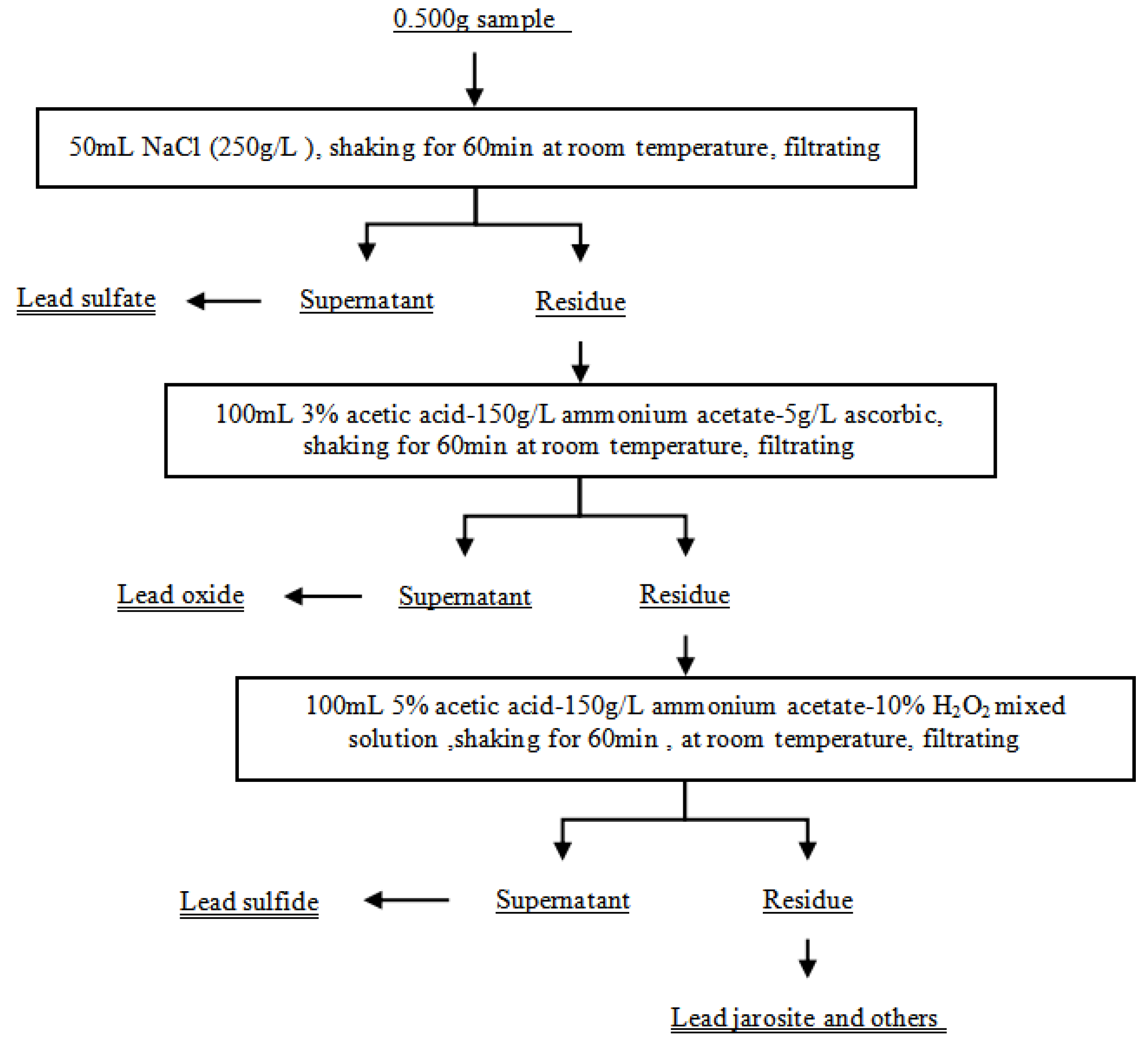
Figure 2.
XRD patterns of PJ-10 in different time periods.

Figure 3.
XRD patterns of PJ 10 compared with NJ and PB.
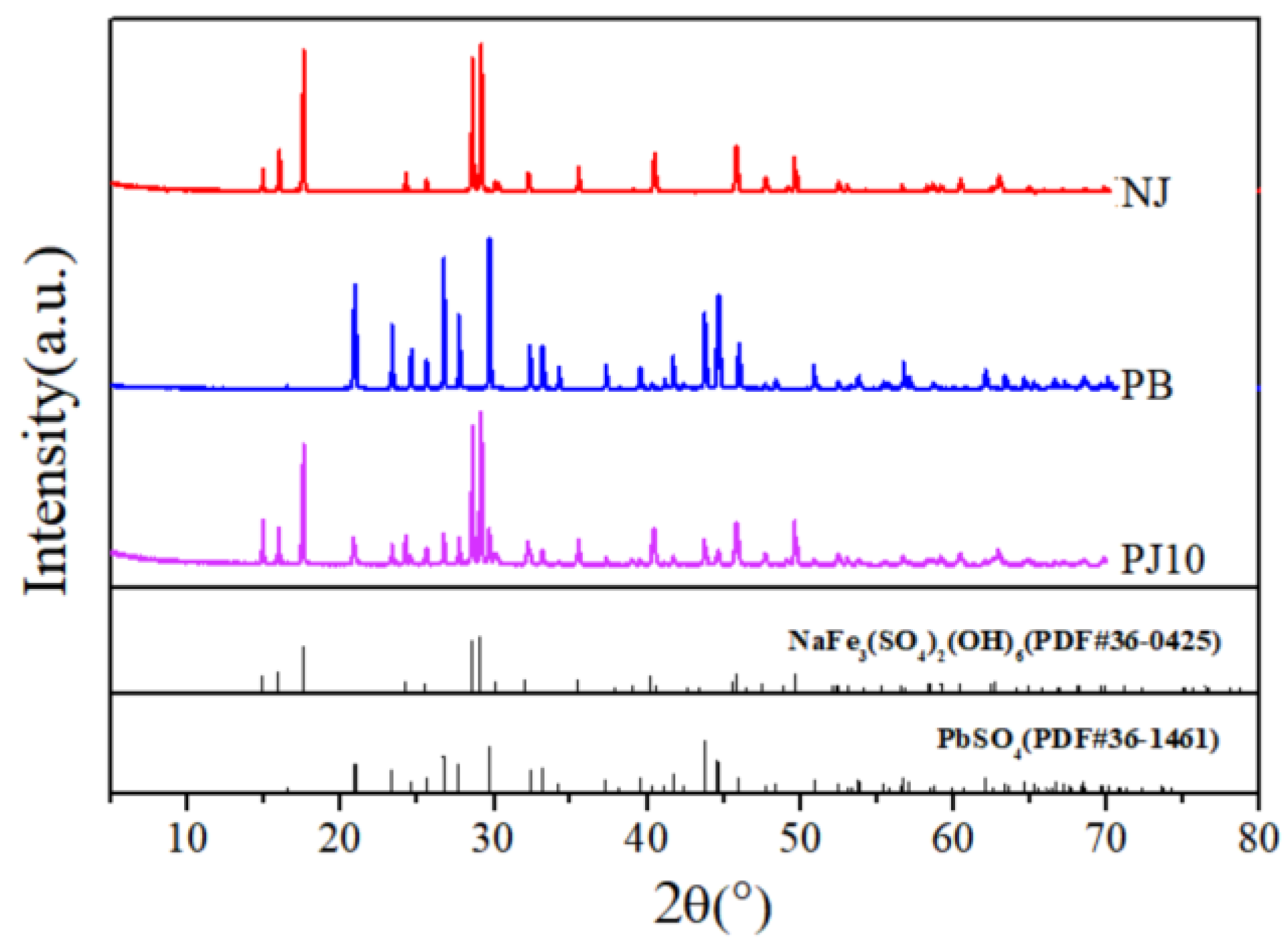
Figure 4.
XRD patterns of SLBJ with different lead contents.
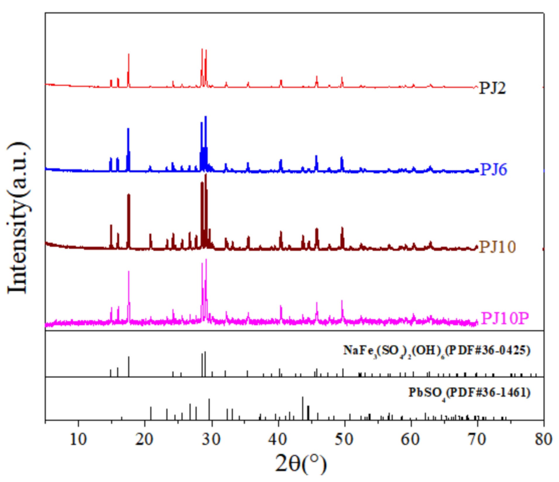
Figure 5.
SEM of the formation process of PJ10 at different times: (a) 5 min, (b) 60 min, and (c) 180 min.
Figure 5.
SEM of the formation process of PJ10 at different times: (a) 5 min, (b) 60 min, and (c) 180 min.

Figure 6.
SEM images and BSE images of PJ10. (a) and (b) are secondary electron images, (c) is the backscattered electron image, and (c)-1 and (c)-2 are the EDS date of points 1 and 2 in (c), respectively.
Figure 6.
SEM images and BSE images of PJ10. (a) and (b) are secondary electron images, (c) is the backscattered electron image, and (c)-1 and (c)-2 are the EDS date of points 1 and 2 in (c), respectively.
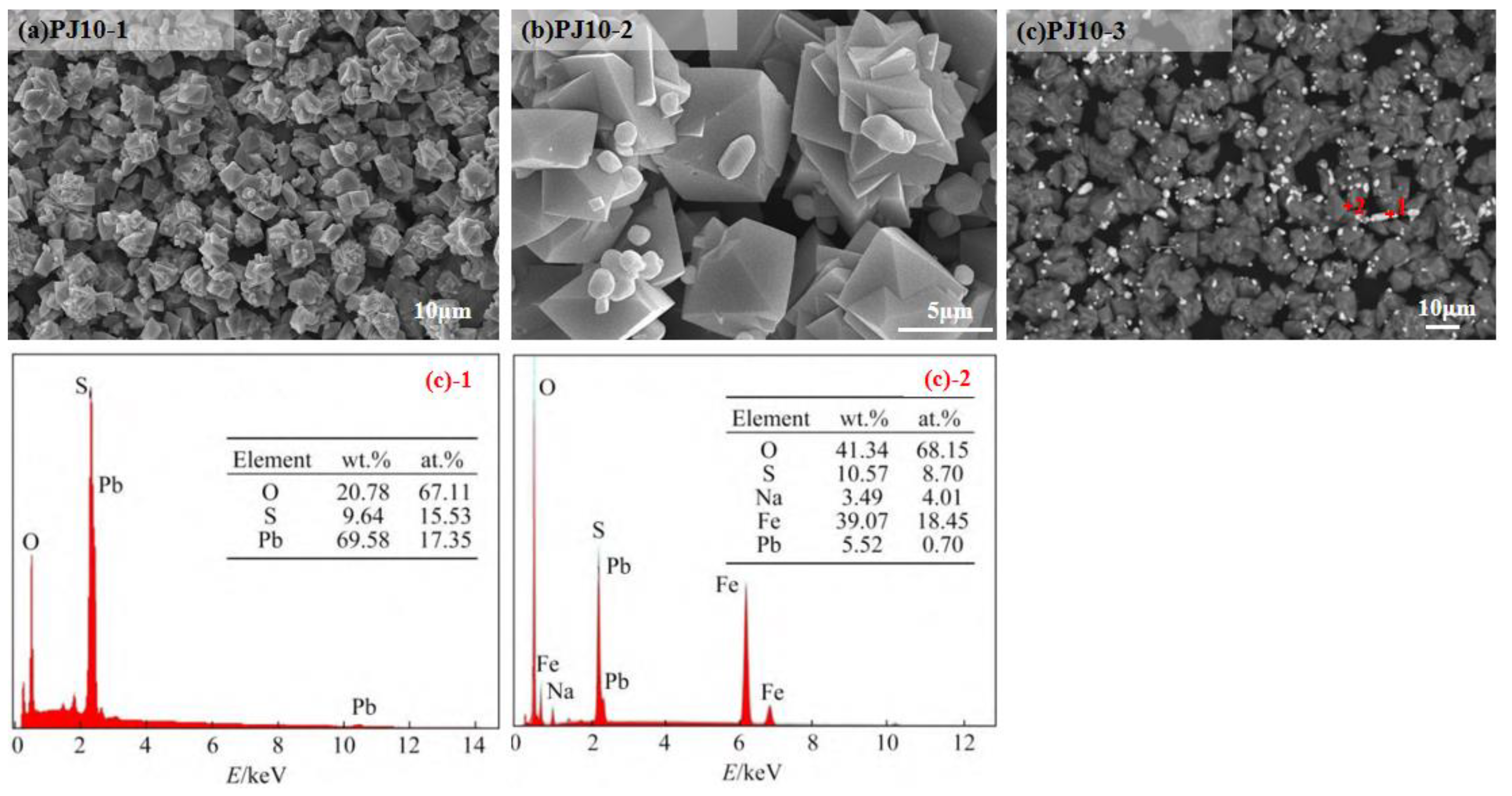
Figure 7.
BSE images of SLBJ with different Pb content. (a,b) are PJ2; (c,d) are PJ6; (e,f) are PJ10.
Figure 7.
BSE images of SLBJ with different Pb content. (a,b) are PJ2; (c,d) are PJ6; (e,f) are PJ10.
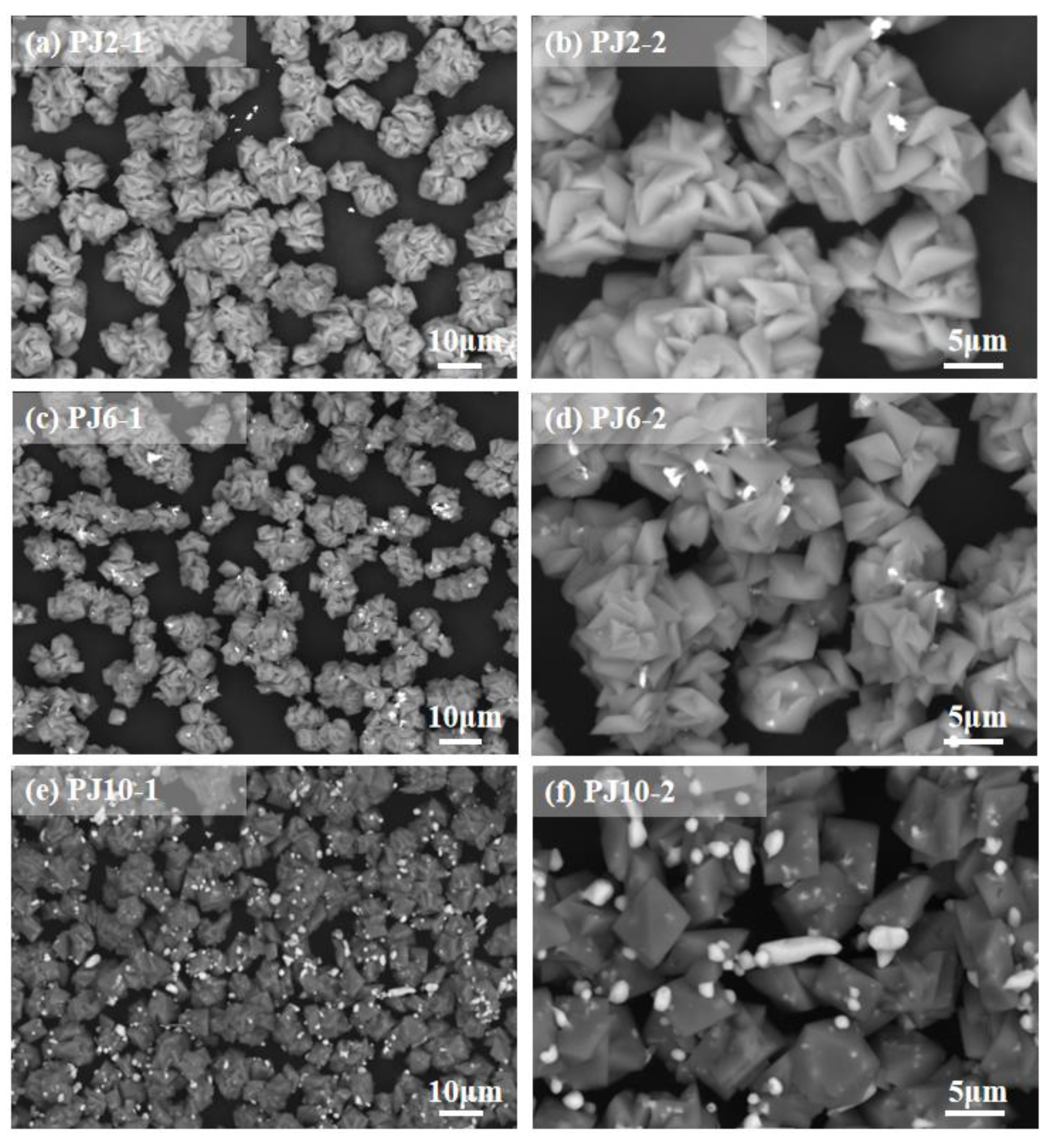
Figure 8.
Back scattered electron image of PJ10.
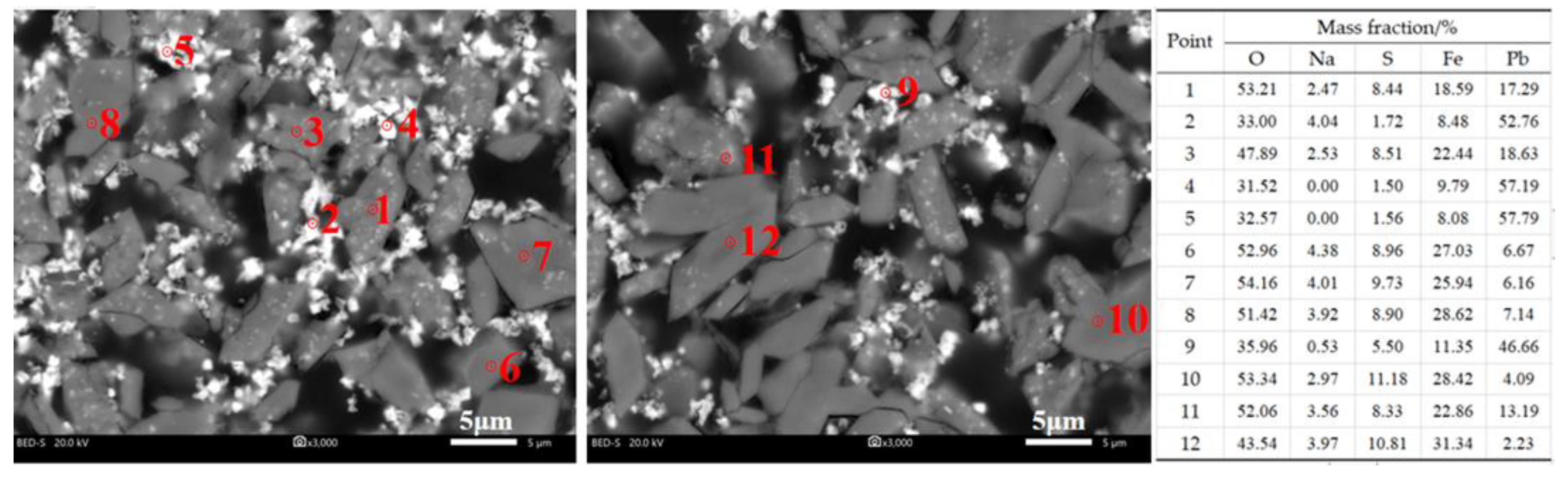
Figure 9.
SEM images of PJ10-P. (a) Mag. 10,000× and (b) Mag. 5000×.

Figure 10.
FTIR spectra of PJ10. (a) PJ10; (b) NJ; (c) PB.

Figure 11.
The XPS spectra of PJ10. (a) Fe2p; (b) O1s; (c) C1s; (d) S2p; (e) Pb4f; (f) full spectrum.
Figure 11.
The XPS spectra of PJ10. (a) Fe2p; (b) O1s; (c) C1s; (d) S2p; (e) Pb4f; (f) full spectrum.

Figure 12.
Particle size distribution of PJ10.

Table 1.
Comparison of TCLP and CSLT Leaching Methods.
| Method | Leaching Reagent | Oscillation Time |
|---|---|---|
| TCLP | CH3COOH (acetic acid); pH 2.88 ± 0.05 | At room temperature for (18 ± 2) h, 30 r/min |
| CSLT-1 (HJ/T 299-2007) | H2SO4 and HNO3 in a mass ratio of 2:1; pH 3.20 ± 0.05 | At room temperature for (18 ± 2) h, 30 r/min |
| CSLT-2 (HJ/T 300-2007) | CH3COOH(glacial acetic acid); pH 2.64 ± 0.05 | At room temperature for (18 ± 2) h, 30 r/min |
Table 2.
Chemical composition of simulated jarosite by chemical analysis (mass fraction, %).
| Sample Name | Main Element Content/% | Na/Fe Molar Ratio | |||
|---|---|---|---|---|---|
| Pb | Fe | Na | S | ||
| PJ2 | 2.27 | 31.8 | 3.45 | 14.4 | 0.26 |
| PJ6 | 5.87 | 31.7 | 3.57 | 14.4 | 0.27 |
| PJ10 | 9.86 | 27.7 | 2.98 | 14.2 | 0.26 |
| PJ10-P * | 7.37 | 31.8 | 3.68 | 14.5 | 0.28 |
* The lead source used in the synthesis is PbSO4, while the others are Pb(CH3COO)2.
Table 3.
The chemical phase of lead in SLBJ with different lead contents.
| Phase | PJ2 | PJ6 | PJ10 | PJ10-P | ||||
|---|---|---|---|---|---|---|---|---|
| w(Pb)/% | Phase Percentage/% | w(Pb)/% | Phase Percentage/% | w(Pb)/% | Phase Percentage/% | w(Pb)/% | Phase Percentage/% | |
| lead sulfate | 0.71 | 31.3 | 1.88 | 32.1 | 3.38 | 34.3 | 5.99 | 81.3 |
| lead oxide | 0.0036 | 0.16 | 0.011 | 0.18 | 0.011 | 0.11 | 0.015 | 0.20 |
| lead sulfide | 0.0007 | 0.03 | 0.004 | 0.06 | 0.008 | 0.08 | 0.001 | 0.02 |
| lead jarosite and others | 1.55 | 68.5 | 3.97 | 67.7 | 6.46 | 65.6 | 1.37 | 18.5 |
| Total | 2.27 | 100 | 5.87 | 100 | 9.86 | 100 | 7.37 | 100 |
Table 4.
Leaching concentrations of PJ10 (mg/L).
| Element | Regulatory Threshold (China) | Regulatory Threshold (USEPA) | Leaching Concentrations | ||
|---|---|---|---|---|---|
| TCLP Method | CSLT-1 Method | CSLT-2 Method | |||
| Pb | ≤5 | ≤5 | 238 | 73.9 | 246 |
Table 5.
Variation of leaching concentration of Pb with time in the continuous leaching experiment of PJ10.
Table 5.
Variation of leaching concentration of Pb with time in the continuous leaching experiment of PJ10.
| No. | Time (h) | Concentration of Lead in Solution (mg/L) | ηPb * (%) |
|---|---|---|---|
| 1 | 24 | 243 | 0.25 |
| 2 | 48 | 242 | 0.74 |
| 3 | 72 | 191 | 1.32 |
| 4 | 96 | 188 | 2.08 |
| 5 | 120 | 186 | 3.03 |
| 6 | 144 | 149 | 3.94 |
| 7 | 168 | 117 | 4.77 |
| 8 | 192 | 90.7 | 5.50 |
| 9 | 216 | 87.6 | 6.30 |
| 10 | 240 | 83.2 | 7.15 |
| 11 | 264 | 80.3 | 8.04 |
| 12 | 288 | 78.6 | 9.00 |
| 13 | 312 | 75.3 | 9.99 |
| 14 | 336 | 70.6 | 11.0 |
| 15 | 360 | 72.0 | 12.1 |
| 16 | 384 | 70.9 | 13.2 |
| 17 | 432 | 78.2 | 14.7 |
| 18 | 456 | 75.7 | 16.1 |
| 19 | 480 | 74.7 | 17.6 |
* ղPb means the proportion of the total accumulate leaching amount in relation to the total lead.
Disclaimer/Publisher’s Note: The statements, opinions and data contained in all publications are solely those of the individual author(s) and contributor(s) and not of MDPI and/or the editor(s). MDPI and/or the editor(s) disclaim responsibility for any injury to people or property resulting from any ideas, methods, instructions or products referred to in the content. |
© 2023 by the authors. Licensee MDPI, Basel, Switzerland. This article is an open access article distributed under the terms and conditions of the Creative Commons Attribution (CC BY) license (https://creativecommons.org/licenses/by/4.0/).
Share and Cite
MDPI and ACS Style
Peng, J.; He, L.; Liu, H.; Sun, Z.; Yan, X. The Synthesis of Lead-Bearing Jarosite and Its Occurrence Characteristic and Leaching Toxicity Evaluation. Metals 2023, 13, 941. https://doi.org/10.3390/met13050941
AMA Style
Peng J, He L, Liu H, Sun Z, Yan X. The Synthesis of Lead-Bearing Jarosite and Its Occurrence Characteristic and Leaching Toxicity Evaluation. Metals. 2023; 13(5):941. https://doi.org/10.3390/met13050941
Chicago/Turabian StylePeng, Jun, Luhua He, Hui Liu, Zhumei Sun, and Xu Yan. 2023. "The Synthesis of Lead-Bearing Jarosite and Its Occurrence Characteristic and Leaching Toxicity Evaluation" Metals 13, no. 5: 941. https://doi.org/10.3390/met13050941
Note that from the first issue of 2016, this journal uses article numbers instead of page numbers. See further details here.