Article

A Novel Lap-Butt Joint Design for FSW of Aluminum to Steel in Tee-Configuration: Joining Mechanism, Intermetallic Formation, and Fracture Behavior

by
Reza Beygi
1,2,*,
Amir Abbas Talkhabi
2,
Majid Zarezadeh Mehrizi
2,
Eduardo A. S. Marques
3,
Ricardo J. C. Carbas
1 and
Lucas F. M. da Silva
3
1
Institute of Science and Innovation in Mechanical and Industrial Engineering (INEGI), Rua Dr. Roberto Frias, 4200-465 Porto, Portugal
2
Department of Materials Engineering and Metallurgy, Faculty of Engineering, Arak University, Arak 38156-8-8349, Iran
3
Department of Mechanical Engineering, Faculty of Engineering of the University of Porto, Rua Dr. Roberto Frias, 4200-465 Porto, Portugal
*
Author to whom correspondence should be addressed.
Metals 2023, 13(6), 1027; https://doi.org/10.3390/met13061027
Submission received: 28 April 2023 / Revised: 19 May 2023 / Accepted: 24 May 2023 / Published: 27 May 2023
(This article belongs to the Special Issue Feature Papers in Structural Integrity of Metals)

Abstract

:
The development of new joint configurations suitable for dissimilar materials enables a wider range of applications and allows for an accelerated replacement of traditional structural construction materials by lightweight materials. The T-configuration is a joint configuration that has not been sufficiently studied for use with dissimilar materials, especially when created using the friction stir welding (FSW) process. In this study, a combined lap/butt design was introduced and implemented, seeking to create a T-joint between aluminum and steel. Characterization of the joints showed that FSW could be successfully used to join aluminum and steel in a T-configuration. The formation of intermetallic bonds and kissing bonds was carefully analyzed, and their contribution to the fracture behavior during loading in the skin and stringer directions was studied. Finite element simulation was used to determine the stress state at the interface during loading. The characterization results showed that the intermetallic, as an indicator of metallurgical bonding, is formed when special features are observed in the pattern of material flow. The fractography images showed that the stress state has a major impact on the fracture. The results of the present study can be effectively used to design and fabricate dissimilar joints, taking into account the loading condition.

Graphical Abstract

1. Introduction

In a vehicle manufacturing context, joining processes that enable efficient joining of dissimilar materials are seen as an important tool to meet increasingly stricter carbon dioxide emission regulations, enabling the manufacture of lightweight multi-material structures [1]. Aluminum is an ideal candidate for use in these structures [2], and successfully joining aluminum to steel (Al/St) is considered one of the most important challenges associated with this type of structure [3]. There are various methods suitable for joining these materials, e.g., cold metal transfer [4], by which Al is fused with a zinc layer on St by low heat input. This process produces fewer intermetallic compounds (IMCs) than fusion welding because the heat input is lower [5]. Mechanical joining methods are also used to join Al to St, such as direct pin pressing [6], by which no IMC is formed. However, mechanical bonding methods show reduced joint integrity and are not flexible enough to be used in some joint configurations. Friction Stir Welding (FSW), as a solid-state joining process, has proven itself in the welding of dissimilar materials [7]. FSW can control the formation of harmful intermetallic compounds (IMCs) of Al-Fe formed during welding [8]. An FSW process creates a bond between dissimilar materials through a combination of metallurgical bonding and mechanical interlocking [9]. The contribution of each mechanism to the joint strength is highly dependent on the process parameters, joint configuration, and loading conditions. The FSW process establishes different joining mechanisms in different joining configurations. In the overlap configuration, for example, the mechanical interlock plays the most important role in joining [10], although it has been reported that a metallurgical bond prevails when the FSW tool does not touch the lower layer [11]. The T configuration has recently attracted a lot of attention due to its greater potential for structural applications [12]. Adhesive bonding is one of the methods commonly used to make T-joints. However, the integrity of adhesively bonded T-joints is significantly compromised by the stress concentration in the corners of the joint that creates the peel stress [13]. Therefore, special modifications of the joint configuration are required to change the state of stress in the joints [14]. Adhesive bonding is often better suited for composite materials, as metallic materials can also be joined using welding processes that are superior to adhesive bonding in some respects. More accurately, welded joints are less sensitive to stress conditions and can preserve joint integrity [15]. The FSW process can be used to join similar metals, but its potential for joining dissimilar metals in a T-configuration is still underexploited [16]. Some studies on FSW welding of dissimilar materials are discussed below.
Rana et al. [17] joined Al sheets to titanium sheets through the FSW process and investigated the joining mechanism. The welding was implemented in lap design in one pass of welding. They reported that mechanical interlock plays an important role in the strength of T-joints. Su et al. [18] joined titanium alloys in T-configuration in two passes of welding in butt welding design. The factor which mostly affected the mechanical properties was the texture of titanium in various regions of the weld. The heat effect of the second pass on the first one can also influence fracture behavior [19]. Doung et al. [20] joined two dissimilar aluminum alloys (AA7075 and AA5083) in a lap configuration with a lap weld design in one pass. They found that the parameters which favor the strength in the skin direction may reduce the joint efficiency in the stringer direction. To obtain a strong weld in the direction of the stringer, the interface of two materials should be mixed properly by the tool action to eliminate the oxide layers at the interface. This needs a long pin, able to penetrate the bottom layer. However, a long pin produces a hook which deteriorates the bond strength in the skin direction. The kissing bond in these configurations occurs mainly in the corner of the fillet and makes it prone to early fracture. To alleviate this problem, Su et al. [21] joined AA5083 aluminum alloy in a T-configuration using a stationary shoulder from the filler corners in two passes. Ultimately, the main defect associated with the T-jointing of Al alloys is the formation of kissing bonds, which affect the joint strength differently in the skin and stringer directions [21]. Jesus et al. [22] observed that butt weld design performs better than a lap configuration for T-joining of Al alloys, as fewer defects are produced during FSW. When dissimilar materials are welded, the aspects of microstructural changes that are affected by the FSW parameters and that can affect mechanical properties differ from those encountered when similar materials are welded. In FSW of similar materials, dynamic recrystallization in the nugget zone plays an important role in determining the mechanical properties of the joint [23]. The presence of nanoparticles in the nugget zone can stimulate dislocation density, which promotes recrystallization in the heat-affected zone. However, it also prevents grain growth [24]. The most important parameters in the heat-affected zone are softening due to the dissolution of precipitates and/or work softening [25]. These aspects are less important in the FSW of dissimilar metals since the main challenge of this process now lies in the formation of brittle IMCs.
T-joints of similar materials created using FSW mostly show ductile fracture behavior [26]. The main initiation sites of failure in these welds are the heat-affected zone (HAZ), process defects, and kissing bonds. T-joining dissimilar materials presents another important challenge in addition to those encountered when welding similar materials. In dissimilar joining, the IMC layer acts as the site for fracture initiation and propagation and causes brittle damage [27]. Depending on the process and geometry, the distribution of the IMC layer can vary along the interface of dissimilar materials [28]. The mechanisms of joining and IMC formation in T-jointing of dissimilar materials are still not well studied, and there are few publications on this subject, some of which had been mentioned in the previous paragraph.
The present study aims to propose a procedure to join Al to St in a T-configuration using FSW, which, to the authors’ knowledge, has not been done before. A combined butt-lap design was developed for joining Al and St in a T-configuration. Characterization of the phases formed during the process was performed, seeking to identify IMC formation and distribution as well as the detection of defects and kissing bond formation. The T-joints manufactured using this process were mechanically tested in both the skin and stringer directions, and their strength was evaluated. The fracture surfaces were carefully studied, and the fracture properties were correlated with the phase characterization results and the mechanical test results. Finite element simulation was used to evaluate the stress state in the joint area during two loading conditions. Finally, a correlation between the joint design and the fracture behavior was made.

2. Materials and Method

A commercially pure aluminum (Al1050) and St37 steel, with sheet thicknesses of 3 and 5 mm, respectively, were selected to be joined by FSW in a T-configuration. For this purpose, a groove was made in Al by removing a rectangle with a width and height of 3 and 3.5 mm, respectively. The edge of St was cleaned and then placed in this groove. To facilitate welding in a T-configuration, a special fixture was designed (Figure 1a) and fabricated (Figure 1b). Al/St was placed in the fixture, as shown in Figure 1c. To produce the FSW tool, tool steel (H13) was machined and then heat treated. Welding was performed from both sides in two separate passes (Figure 1c). The position of the tool with respect to the sheets is shown in Figure 1c,d. An offset of 0.5–1 mm of the tool in St was chosen to ensure metallurgical bonding. For each pass, St was placed on the advancing side. FSW was performed in a position control mode with a shoulder plunge depth of 0.2 mm into the workpiece. The rotation speed was 950 rpm, and the welding speed was 30 mm/min, according to previous studies [29].
After the weld was completed, the specimens were cut into several pieces for tensile testing and joint characterization (Figure 2). Cutting was done through electrical discharge machining to minimize deleterious mechanical effects on the joints. The width of the specimens used for tensile testing was 13.5 mm.
Some of the samples were embedded in resin and then polished with mechanical grinding and diamond paste to aid subsequent observation under optical and scanning electron microscopy. For optical microscopy, a two-step etching method was used to reveal the microstructure of Al and St. First, Picral plus Keller was used for steel, and then a solution of Acetic acid (10 mL) plus Picric acid (4.2 g) plus H2O (40 mL) was used for Al. To prepare the samples for SEM imaging, cross-sections of resin-mounted joints were polished with increasingly finer grits of sandpaper (from P80 to P2500). The specimens were then polished with diamond paste (1.5 µm) and then directly examined by SEM without any etching. Both secondary electron (SE) and backscattered electron (BSE) analyses were used in SEM to observe the morphology and phase distribution in the joint region. BSE can be effectively used to distinguish between Al, St, and Al-St IMCs due to the contrast resulting from the chemical composition. The SE mode was used to observe defects in the cross-section of the joints. It was also used to see the fracture surfaces of the failed specimens after the tensile test. Energy dispersion spectroscopy (EDS) was used to determine the chemical composition of the phases.
Two loading conditions were used to determine the strength of the joints: the skin direction and the stringer direction, as seen in Figure 3a,b, respectively. A custom fixture was designed (Figure 3b) and fabricated (Figure 3c) to allow for an examination of the joint strength in the stringer direction. Tensile testing was performed at a cross-head speed of 2 mm/min for both skin and stringer directions (Figure 3d). This test rate was chosen to evaluate the strength of the joints under quasi-static loading [30]. Three specimens were tested for each loading condition to ensure result repeatability. Load-displacement curves were recorded during the tensile test, and the maximum load was recorded for the ultimate fracture load (or the ultimate tensile strength). The tested specimens were further analyzed using SEM to study the fracture surface and to investigate the mechanism of fracture.
The Abaqus finite element software was used to simulate the loading process in the skin and stringer directions, allowing the determination of the stress state at the joint interface. The joint geometry was simplified, as shown in Figure 4a. The model used a two-dimensional (2D) configuration, using a shell geometry with a thickness of 13.5 mm. The elastic-plastic behavior of the materials followed the data reported in a previous paper by the authors [9]. Triangular elements were chosen for Al and St, and rectangular elements were chosen for the interface (Figure 4b). The element types used to model the materials and interface were the CPE3 and CPE4R types, respectively. A quasi-static explicit analysis was used to solve the model.

3. Results

From this section onward, the T-joint is represented as vertically reversed, leaving the stringer (St) on top and the skin (Al) on the bottom. The macrostructure of the joint is presented in Figure 5. In this scale, no defect can be seen, which shows that the process parameters were correctly defined. The boundary between the nugget zone and the base material (or heat-affected zone) is clearly visible, while some entrained particles of St can be observed in the nugget zone. St was thinned in the middle of the nugget zone, which is the direct result of the tool offset used during the FSW process.
Higher magnification images of the joint zone are provided in Figure 6. At this stage, only the microstructure of the Al/St interface was studied as the samples failed at the interface. The other areas, such as the heat-affected zone (HAZ) and the thermomechanically affected zone (TMAZ), were not studied as they did not contribute to the failure. The main purpose of this optical microscopy observation was to identify defects and material flow in the joint area. Different parts of the joint were selected and viewed at different magnifications. Figure 6a–c shows the images taken from the dragged particle of St in the Al matrix. No defect is observed at the interface. The pattern of material flow is visible in the optical images, showing that the directions of material flow around the interface are parallel on two sides of the interface. Figure 6d shows the inner region of the end face of St in the Al matrix. Detached Al fragments can be observed in the St matrix. The material flow at the interfaces of Al/St is crossed, and no flow appears to occur in Al. Figure 6e shows the outer region of the end face of St, where the flow lines of Al just near the interface appear to be bent parallel to the interface. The regions shown in Figure 6d,e were under the influence of the shoulder and pin without direct contact with St with the tool. Figure 6f shows the Al/St interface at a location where there was direct contact between the tool and St. The flow lines are parallel on two sides of the interface. Figure 6g shows the Al/St interface that was under the influence of the bottom of the pin without direct contact with the pin. The patterns of material flow show that St was bent and pulled far away from the pin by the influence of Al flow. In fact, the pin did not have any direct role in the flow of St. The flow lines on two sides of the interface are completely crossed at the interface and thus are non-parallel. Figure 6h shows the Al/St interface that was under the influence of and in direct contact with the bottom of the pin. The flow lines on both sides of the interface are parallel. These results imply that the flow lines are parallel on two sides of the interface when the tool is in direct contact with St.
It should be noted that neither the IMC nor the microscopic defects at the interface can be observed in the optical microscopy images. For the observation of IMCs and micro defects, only the SEM technique can provide useful images. Figure 7a shows the cross-section of the weld corresponding to the second pass of the weld. Figure 7b shows a BSE SEM image of the vertical interface where the pin was in direct contact with St during the FSW. Figure 7c,d show SE and BSE images taken at higher magnification in the area where there was no direct contact with the pin. A gap can be seen in this area, indicating a kissing bond. No protrusion of Al into St is observed in this region. This region corresponds to the regions shown in Figure 6g, where the flow lines were unparallel on two sides of the interface. Figure 7e–g shows the SEM images taken from various parts of the interface of Al/St located at the bottom of the pin on the right side (the first pass). The regions away from the pin periphery possess a kissing bond (Figure 7c,d,f–h), while the regions in contact with the pin exhibit an IMC layer at the interface showing a bond (Figure 7b). The interface shown in Figure 7b corresponds to Figure 6h, where the flow lines are parallel on two sides of the interface. The SEM images with kissing bond correspond to Figure 6g, where the flow lines are crossed at the interface.
Figure 8a–f shows SEM images from the end-face of St, which is influenced by both the shoulder and the pin. A few entrapped Al fragments can be observed inside this part of St. This is due to the mixed upward-lateral flow of St that occurred in two passes on two sides during FSW. The interfaces of Al/St in this region are all of the kissing bond type, around which the material flow lines are crossed (Figure 6d).
Figure 9a,b shows the SEM images of the vertical Al/St interface created during the second and first welding passes, respectively. In the second pass, the interface is non-uniform, and the thickness of the IMC layer varies between 1.0–3.5 μm. The IMC layer in the first pass is uniform, with an average thickness of 5 μm. The flow lines around these interfaces are parallel, as shown in Figure 6f. EDS line scan analyses across the interfaces (yellow lines) are provided in Figure 9c,d. The presence of a gradient of the Fe and Al elements at the interface is an indicator of the presence of the IMC layer.
Figure 10a shows the load-displacement curves obtained from testing the joints in the skin and stringer directions. Figure 10b shows a schematic representation of the joints’ failure process. When the joint is loaded in the direction of the stringers, both the maximum load and the ductility are higher than when the joints are loaded in the direction of the skin. This suggests that the St is pulled out from Al when the joint is loaded in the stringer direction. In contrast, when loaded in the skin direction, the specimen failed along the Al/St interface of the first pass.
Figure 11 shows SEM images of different parts of the fracture surface of the joint loaded in the skin direction. Region a (Figure 11a) shows the fracture through Al. This area failed in a ductile manner due to the absence of the Al/St interface. The fracture surface shown in Figure 11b (region b) exhibits dimples indicative of ductile damage, which corresponds to the interface shown in Figure 7b and Figure 6h. The SEM images shown in Figure 11c–e (Regions d and c) are the images of the fracture surfaces taken from the St and Al sides, respectively. These brittle fracture surfaces correspond to the vertical Al/St interface shown in Figure 10 and Figure 6f. In fact, this fracture surface is a pseudo-brittle one whose mechanism has been thoroughly explained in a previous paper by the authors [31]. The tearing ridges of this fracturing process can be observed in Figure 11e.
The SEM images of the fracture surface of different areas of the specimen tested in the stringer direction are shown in Figure 12. Figure 12a shows the fracture surface from the Al side of the vertical interface corresponding to Figure 6f and Figure 10. Dimples are evident in this area, again indicating a ductile fracture. A low-magnification image of the fracture surface from the St side of the interface, corresponding to Figure 6f and Figure 10, is shown in Figure 12b. Highlighted blue regions in this figure correspond to the interfaces shown in Figure 6d,h. Higher magnification images shown in Figure 12c show the dimples whose EDS analysis is provided below. The EDS analysis results only show Al, indicating that the fracture has started on the Al base material, close to the Al/St interface. Figure 12d shows the SEM image of the fracture surface, whose brittle region corresponds to the interface shown in Figure 6h. A higher magnification of this surface is provided in Figure 12e, whose EDS analysis is provided below. The presence of both Al and Fe indicates that fracture has occurred through the IMC layer. Figure 12f shows the SEM image of the fracture surface from the end-face of St. The brittle region corresponds to the interface shown in Figure 6d. Figure 12g shows the fracture surface presenting a brittle region consistent with region d. The higher magnification of the ductile region shown in Figure 12h is similar to that of region d.

4. Discussion

The results of the metallographic examination and the SEM images show that when the flow lines on both sides of the Al/St interface are parallel, there is a metallurgical bond presenting a layer of IMC compound at the interface. This happens when the probe, which is inside the Al matrix, comes into contact with St. Otherwise, a “kissing bond” will form, causing an incomplete bond between Al and St. This “kissing bond” is unavoidable because the length of the pin should be less than the thickness of the Al so that the lower part of the specimen does not come into contact with the pin. This kissing bond, which exists in the fillet corner (see Figure 13a), has been previously reported during the T-joining of Al alloys by FSW [20]. The entrapped Al fragment inside the steel at the end-face of St (Figure 6d) is due to the combined upward and inside-lateral flow of St in the first and second welding passes (Figure 13a). This flow of material leads to the formation of a hook that obstructs the flow of Al on the other side. The two hooks formed in two passes converge and trap Al. Since there is no flow in this confined Al region, no Al/St interface bonding forms in this region (as seen in Figure 8).
Since the process is performed in two passes, the IMC layer at the Al/St interface is not uniform. Shoulder and pin contribute mainly to the nucleation and growth of the IMC layer during FSW, respectively [32]. The interface at the first welding pass is affected by the heat of the second pass, which leads to the growth of the previously formed IMC layer (see Figure 13a,b). Moreover, the discontinuities of the IMC layer at the interface disappear, resulting in a uniform IMC layer there. This causes the fracture toughness of the interface to decrease [30] and will therefore cause the joint to fail when loaded in the skin direction at the interface of the first weld pass. The disappearance of discontinuities during the second pass is attributed to the higher diffusion rate of atoms at the curvatures. The flux of atoms at the tip of a curve ( J ) is obtained from [33]:
J = J 0 ( 1 + γ Ω k T K )
where J 0 is the flux of atoms across a flat interface, γ is the surface energy, T is temperature, k is Boltzmann’s constant, Ω is the atomic volume, and K is the curvature. A high curvature at the interface between IMC and St causes the J-value to be so high that the curvatures grow rapidly and turn into flat surfaces (Figure 13c). Therefore, the IMC layer in the first weld is thicker and straight due to the heat effect of the second weld on the first, while the IMC layer in the second weld is irregular and thin (see Figure 13b). This causes the first weld to be weak, and for this reason, during a tensile test in the skin direction, the joint fails at the interface of the first weld.
The effect of heat generated during the second pass on the first pass in T-joints was also observed during similar joining of Al alloys [21]. In this case, the joint failed from the HAZ of the first pass, where the hardness was reduced due to the additional heat delivery.
The fracture surface results show that the fracture pattern obtained under loading in the stringer direction is not the same as that found for loading in the skin direction. Based on these observations, it becomes possible to identify the pattern of the fracture surface in each loading condition. The schematics of fracture mechanisms in both loading conditions are shown in Figure 14. These interfaces, which appear to have experienced brittle failure when loaded in the direction of the stringers, exhibited a morphology typical of ductile fracture when loaded in the direction of the skin and vice versa. This can be due to the stress state at the interface, which must be determined for the two loading conditions. This was achieved with the FE simulation, and the obtained results are presented below.
The results of the FE simulations help to understand the stress state along the Al/St interfaces in various locations of the joints. Matching these results with previous observations helps to correlate the fracture behavior with the loading condition. Figure 15a,b shows the shear stress and normal stress developed during loading in the direction of the skin, respectively. Figure 16a,b shows the shear stress and normal stress developed during loading in the direction of the stringer, respectively. The schematic representation of the fracture surfaces in Figure 14 has been added for a better understanding of the fracture mechanism. Figure 17a–d shows the tensile and shear stress distribution along the Al/St interfaces in two loading conditions. These results were obtained when the applied external loads during the simulation were slightly lower than the experimentally determined failure loads. According to these results, the vertical interface is under tensile and shear stress when loaded in the skin and stringer directions, respectively. The opposite holds for the horizontal interface. These results also show that, under shear loads, the interface fails in a ductile manner. In contrast, the failure is brittle when the joint is loaded in the normal direction. In a ductile fracture, which occurs under shear stress, failure occurs from the parent material Al. In ductile fracture, which occurs during tensile loading, failure occurs at the interface of the IMC layer.
The results of the present study show that joining Al/St in T configuration by FSW is technically feasible. The present study dealt with a T-joint in which Al was used as the skin. If St is to be placed as skin, a new procedure needs to be developed and modified. The results also show that the Al/St interface, which contains a brittle IMC layer, acts more strongly under shear loading. In this case, the Al near the interface fails in a ductile manner so that the surface of St after fracture is covered by Al. These results can be used for designing the joint geometry of Al/St, doing so in a manner that ensures that the interface is under shear load to prevent catastrophic failure.

5. Conclusions

A successful Al/St-T joint was created using the FSW process in two passes, where Al was the skin and St was the stringer. The obtained joints were completely metallurgical, without any mechanical interlock. The following results were obtained after the characterization of the joints:
1-
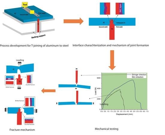
The material flow around the tool can form a metallurgical bond only if the flow lines of the two materials (Al and St) are in the same direction. Otherwise, a “kissing bond” is formed, which has very low strength. No IMC layer was observed in these kissing bonds;
2-
The thickness of the IMC layer is slightly higher in the first welding pass, which is due to the heat effect of the second welding pass. As a result, the irregularities formed at the interface in the first pass disappear in the second pass, mainly due to the growth of IMC. This leads to a weakening of this interface and leads to its failure during the tensile test in the direction of the skin;
3-
The fracture load is higher when the load is applied in the stringer direction. In this state, a larger part of the interface is in the shear mode. In this mode, the Al/St interface breaks in a ductile manner through the Al instead of undergoing a brittle fracture through the IMC layer.

Author Contributions

Conceptualization, R.B. and L.F.M.d.S.; Methodology, A.A.T. and M.Z.M.; Validation, R.J.C.C.; Formal Analysis, R.B. and E.A.S.M.; Writing—Original Draft Preparation, R.B.; Writing—Review & Editing, E.A.S.M., M.Z.M. and R.J.C.C.; Supervision, L.F.M.d.S. All authors have read and agreed to the published version of the manuscript.

Funding

The authors acknowledge the funding under the reference “UIDP/50022/2020—LAETA—Laboratório Associado de Energia, Transportes e Aeronáutica”. The authors also thank Arak University for the facilities provided for the friction stir welding process.

Data Availability Statement

Not applicable.

Conflicts of Interest

The authors declare no conflict of interest.

References

  1. Gullino, A.; Matteis, P.; D’aiuto, F. Review of aluminum-to-steel welding technologies for car-body applications. Metals 2019, 9, 315. [Google Scholar] [CrossRef]
  2. Rostamiyan, Y.; Seidanloo, A.; Sohrabpoor, H.; Teimouri, R. Experimental studies on ultrasonically assisted friction stir spot welding of AA6061. Arch. Civ. Mech. Eng. 2015, 15, 335–346. [Google Scholar] [CrossRef]
  3. Huang, Y.; Wan, L.; Meng, X.; Xie, Y.; Lv, Z.; Zhou, L. Probe shape design for eliminating the defects of friction stir lap welded dissimilar materials. J. Manuf. Process. 2018, 35, 420–427. [Google Scholar] [CrossRef]
  4. Singh, J.; Arora, K.S.; Shukla, D.K.; Kumar, H. Mechanical and microstructural characterization of cold metal transfer (CMT) spot aluminium-steel weld-brazed joints. Proc. Inst. Mech. Eng. Part L J. Mater. Des. Appl. 2022, 236, 2506–2515. [Google Scholar] [CrossRef]
  5. Xu, P.; Hua, X.; Shen, C.; Huang, Y.; Li, F.; Zhang, Y. Dynamic growth model of Fe2Al5 during dissimilar joining of Al to steel using the variable polarity cold metal transfer (VP-CMT). J. Mater. Process. Technol. 2022, 302, 117477. [Google Scholar] [CrossRef]
  6. Römisch, D.; Kraus, M.; Merklein, M. Investigation of the influence of formed, non-rotationally symmetrical pin geometries and their effect on the joint quality of steel and aluminium sheets by direct pin pressing. Proc. Inst. Mech. Eng. Part L J. Mater. Des. Appl. 2022, 236, 1187–1202. [Google Scholar] [CrossRef]
  7. Wang, X.; Lados, D.A. Optimization of aluminum-to-steel friction stir lap welding for the fabrication of high-integrity structural components. J. Adv. Join. Process. 2022, 5, 100114. [Google Scholar] [CrossRef]
  8. Beygi, R.; Carbas, R.; Queiros, A.; Marques, E.A.S.; Shi, R.; da Silva, L.F.M. Comparative Study Between Stainless Steel and Carbon Steel During Dissimilar Friction Stir Welding with Aluminum: Kinetics of Al–Fe Intermetallic Growth. Met. Mater. Int. 2022, 28, 1948–1959. [Google Scholar] [CrossRef]
  9. Beygi, R.; Akhavan-Safar, A.; Carbas, R.; Barbosa, A.; Marques, E.; da Silva, L. Utilizing a ductile damage criterion for fracture analysis of a dissimilar aluminum/steel joint made by friction stir welding. Eng. Fract. Mech. 2022, 274, 108775. [Google Scholar] [CrossRef]
  10. Liu, H.; Chen, Y.; Yao, Z.; Lou, F. Effect of tool offset on the microstructure and properties of AA6061/AZ31B friction stir welding joints. Metals 2020, 10, 546. [Google Scholar] [CrossRef]
  11. Matsuda, T.; Ogaki, T.; Hayashi, K.; Iwamoto, C.; Nozawa, T.; Ohata, M.; Hirose, A. Fracture dominant in friction stir spot welded joint between 6061 aluminum alloy and galvannealed steel based on microscale tensile testing. Mater. Des. 2022, 213, 110344. [Google Scholar] [CrossRef]
  12. Hashem, M.; Wagih, A.; Lubineau, G. Laser-based pretreatment of composite T-joints for improved pull-off strength and toughness. Compos. Struct. 2022, 291, 115545. [Google Scholar] [CrossRef]
  13. Carvalho, P.M.D.; Campilho, R.D.S.G.; Sánchez-Arce, I.J.; Rocha, R.J.B.; Soares, A.R.F. Adhesively-bonded T-joint cohesive zone analysis using dual-adhesives. Procedia Struct. Integr. 2022, 41, 24–35. [Google Scholar] [CrossRef]
  14. Nejad, R.M.; Moghadam, D.G.; Hadi, M.; Zamani, P.; Berto, F. An investigation on static and fatigue life evaluation of grooved adhesively bonded T-joints. Structures 2022, 35, 340–349. [Google Scholar] [CrossRef]
  15. Nonnenmann, T.; Beygi, R.; Carbas, R.; da Silva, L.; Öchsner, A. Feasibility study on hybrid weld-bonding between dissimilar material for automotive industry. Int. J. Adhes. Adhes. 2023, 121, 103316. [Google Scholar] [CrossRef]
  16. Sun, T.; Roy, M.J.; Strong, D.; Simpson, C.; Withers, P.J.; Prangnell, P.B. Weld zone and residual stress development in AA7050 stationary shoulder friction stir T-joint weld. J. Mater. Process. Technol. 2019, 263, 256–265. [Google Scholar] [CrossRef]
  17. Rana, H.; Campanella, D.; Buffa, G.; Fratini, L. Dissimilar titanium-aluminum skin-stringer joints by FSW: Process mechanics and performance. Mater. Manuf. Process. 2022, 38, 471–484. [Google Scholar] [CrossRef]
  18. Su, Y.; Li, W.; Gao, F.; Vairis, A. Effect of FSW process on anisotropic of titanium alloy T-joint. Mater. Manuf. Process. 2021, 37, 25–33. [Google Scholar] [CrossRef]
  19. Su, Y.; Li, W.; Liu, X.; Gao, F.; Yu, Y.; Vairis, A. Strengthening mechanism of friction stir welded alpha titanium alloy specially designed T-joints. J. Manuf. Process. 2020, 55, 1–12. [Google Scholar] [CrossRef]
  20. Duong, H.D.; Okazaki, M.; Tran, T.H. Influence of probe length on the formation of an interface in friction stir welded T-lap joints. Mater. Manuf. Process. 2021, 36, 693–701. [Google Scholar] [CrossRef]
  21. Su, Y.; Li, W.; Patel, V.; Vairis, A.; Wang, F. Formability of an AA5083 aluminum alloy T-joint using SSFSW on both corners. Mater. Manuf. Process. 2019, 34, 1737–1744. [Google Scholar] [CrossRef]
  22. Jesus, J.; Costa, J.; Loureiro, A.; Ferreira, J. Assessment of friction stir welding aluminium T-joints. J. Mater. Process. Technol. 2018, 255, 387–399. [Google Scholar] [CrossRef]
  23. Chaudry, U.M.; Han, S.C.; Jun, T.S. Effect of welding speed on the microstructure and texture development in the individual weld zone of friction stir welded DP780 steel. J. Mater. Res. Technol. 2023, 23, 4976–4989. [Google Scholar] [CrossRef]
  24. Liu, T.S.; Qiu, F.; Yang, H.Y.; Shu, S.L.; Xie, J.F.; Jiang, Q.C.; Zhang, L.C. Insights into the influences of nanoparticles on microstructure evolution mechanism and mechanical properties of friction-stir-welded Al 6061 alloys. Mater. Sci. Eng. A 2023, 871, 144929. [Google Scholar] [CrossRef]
  25. Kumar, K.K.; Kumar, A.; Nagu, K. Mechanical and Corrosion Behaviour of Friction Stir Welded 5083–6061 Aluminium Alloy Joints: Effect of Base Material Position. Trans. Indian Inst. Met. 2023, 1–12. [Google Scholar] [CrossRef]
  26. Su, Y.; Li, W.; Shen, J.; Fu, B.; dos Santos, J.F.; Klusemann, B.; Vairis, A. Comparing the local-global deformation mechanism in different friction stir welding sequences of Ti-4Al-0.005B titanium alloy T-joints. Mater. Sci. Eng. A 2021, 823, 141698. [Google Scholar] [CrossRef]
  27. Beygi, R.; Galvão, I.; Akhavan-Safar, A.; Pouraliakbar, H.; Fallah, V.; da Silva, L.F.M. Effect of Alloying Elements on Intermetallic Formation during Friction Stir Welding of Dissimilar Metals: A Critical Review on Aluminum/Steel, Mdpi.Com. (n.d.). Available online: https://www.mdpi.com/2075-4701/13/4/768 (accessed on 28 April 2023).
  28. Karimi-Dermani, O.; Abbasi, A.; Roeen, G.A.; Nayyeri, M.J. A novel approach to dissimilar joining of AA7075 to AZ31B by friction stir soldering using Sn intermediate layer. Mater. Manuf. Process. 2022, 37, 942–955. [Google Scholar] [CrossRef]
  29. Beygi, R.; Carbas, R.; Barbosa, A.; Marques, E.; da Silva, L. Buttering for FSW: Enhancing the fracture toughness of Al-Fe intermetallics through nanocrystallinity and suppressing their growth. J. Manuf. Process. 2023, 90, 233–241. [Google Scholar] [CrossRef]
  30. Beygi, R.; Mehrizi, M.Z.; Akhavan-Safar, A.; Safaei, S.; Loureiro, A.; da Silva, L.F.M. Design of friction stir welding for butt joining of aluminum to steel of dissimilar thickness: Heat treatment and fracture behavior. Int. J. Adv. Manuf. Technol. 2021, 112, 1951–1964. [Google Scholar] [CrossRef]
  31. Beygi, R.; Carbas, R.; Barbosa, A.; Marques, E.; da Silva, L.F.M. A comprehensive analysis of a pseudobrittle fracture at the interface of intermetallic of η and steel in aluminum/steel joints made by FSW: Mi-crostructure and fracture behavior. Mater. Sci. Eng. A 2021, 824, 141812. [Google Scholar] [CrossRef]
  32. Tanaka, T.; Nezu, M.; Uchida, S.; Hirata, T. Mechanism of intermetallic compound formation during the dissimilar friction stir welding of aluminum and steel. J. Mater. Sci. 2020, 55, 3064–3072. [Google Scholar] [CrossRef]
  33. Sieradzki, K. Curvature Effects in Alloy Dissolution. J. Electrochem. Soc. 1993, 140, 2868–2872. [Google Scholar] [CrossRef]
Figure 1. (a) Drawing of the fixture used to perform the T-joint. (b) The fixture for T-joining. (c) The schematic of the process shows Al and St sheets and the location of the first and second welds. (d) Positioning of the tool with respect to the specimen.
Metals 13 01027 g001
Figure 2. (a) Crown of the weld showing the skin side of the T-joint. (b) Cut specimens that were used for both microstructure and mechanical testing.
Metals 13 01027 g002
Figure 3. (a,b) Schematic of the tensile tests used for determination of the joint strength in the skin as well as stringer directions. (c) Fixture used for tensile testing in stringer direction. (d) Tensile testing in the stringer direction.
Metals 13 01027 g003
Figure 4. (a) Schematic of the joint geometry used for the FE simulation. (b) Mesh shape and elements used for the simulation.
Metals 13 01027 g004
Figure 5. Cross section of Al-St T-joint showing the interface and the nugget zone.
Metals 13 01027 g005
Figure 6. Metallography image of various zones of the weld region. (a0) The macrograph of the weld. (ac) Around the St fragment in the matrix of Al. (d,e) From the end-face of St in the junction of pin- and shoulder-influenced region. (f) From the interface around the pin-contacted region. (g) Under the pin without contact with the pin. (h) Under the pin with the contact of the bottom of the pin.
Metals 13 01027 g006
Figure 7. (a0) The macrograph of the weld. (ad) SEM images of the second weld pass of the T-joint taken from the bottom of the pin. (eh) SEM images of the first weld pass of the T-joint taken from the bottom of the pin.
Metals 13 01027 g007
Figure 8. (a0) Macrograph of the weld with the rectangle marking the end-face of St in the pin- and shoulder-influenced region. (a) BS SEM image of this region. (b,c) SE and BSE images of the Al/St. (df) Higher magnification SE and BSE images of the Al/St interface.
Metals 13 01027 g008
Figure 9. (a0) The macrograph of the weld. (a,b) The vertical Al/St interface of the second and first weld, respectively. (c,d) Chemical line scan analysis across the interface along the yellow lines marked in a and, respectively. The color maps of elements are provided as insets.
Metals 13 01027 g009
Figure 10. (a) Load-displacement curves of the Al/St T-joint tested in skin and stringer directions. (b) The schematic of the T-joint failure under two loading conditions was drawn from the real tested specimens.
Metals 13 01027 g010
Figure 11. (a0) The joint after fracture. SEM images of the fracture surface of Al/St T-joint loaded in the skin direction taken from various regions; (a) from Al, (b) from region b, which was in shear loading, (c) from region c in Al, which was in normal loading, and (d,e) from the St interface which was in normal loading. (f) The schematic of the fractured joint with different regions marked.
Metals 13 01027 g011
Figure 12. (a0) The joint after fracture. SEM images of the fracture surface of Al/St T-joint loaded in the stringer direction taken from various regions; (a) from Al of the vertical interface, (b) from St of the vertical interface. The highlighted blue regions show the brittle fracture. (c) Higher magnification from the St side of the vertical interface. (d) From the Al side of the horizontal interface. (e) Higher magnification image thereof. (f) From Al in contact with the end-face of St. (g) From Al of the vertical interface. (h) Higher magnification image thereof. (i) The schematic of the fractured joint with different regions marked. (j) The EDS analyses taken from brittle and ductile regions.
Metals 13 01027 g012
Figure 13. (a) Schematic of FSW during the second welding pass. The red arrows show the direction of material flow in the second pass. The black arrows show the flow of heat from the second pass to the first pass, causing the IMC layer to grow. (b) The interfaces of Al/St in the second and first pass (see also Figure 9a,b). (c) The rapid growth of the tip curvatures of the IMC layer of the first weld due to the heat of the second weld.
Metals 13 01027 g013
Figure 14. Schematic of T-joint failure under (a) stringer loading, (b) skin loading.
Metals 13 01027 g014
Figure 15. (a) The shear and (b) tensile stresses developed in the T-joint loaded in the skin direction. The arrows point to the schematics of fracture.
Metals 13 01027 g015
Figure 16. The (a) shear and (b) tensile stresses developed in the T-joint loaded in the stringer direction. The arrows point to the schematics of fracture.
Metals 13 01027 g016
Figure 17. The tensile and shear stress distribution along the interfaces of the Al/St (a,c) correspond to the vertical interfaces, and (b,d) correspond to the horizontal interfaces shown above the diagrams in two loading conditions. (a,b) correspond to the skin loading, and (c,d) correspond to the stringer loading.
Metals 13 01027 g017
Disclaimer/Publisher’s Note: The statements, opinions and data contained in all publications are solely those of the individual author(s) and contributor(s) and not of MDPI and/or the editor(s). MDPI and/or the editor(s) disclaim responsibility for any injury to people or property resulting from any ideas, methods, instructions or products referred to in the content.

