Article

Selective Cementation of Gold Using an Iron Oxide and Zero-Valent Aluminum Galvanic System from Gold–Copper Ammoniacal Thiosulfate Solutions

1
Laboratory of Chemical Resources, Division of Sustainable Resources Engineering, Graduate School of Engineering, Hokkaido University, Sapporo 060-8628, Japan
2
Department of Materials and Resources Engineering, College of Engineering and Technology, Mindanao State University-Iligan Institute of Technology, Iligan City 9200, Philippines
3
Department of Earth Resource Engineering and Environmental Science, Faculty of International Resources Science, Akita University, Akita 010-0865, Japan
4
Division of Sustainable Resources Engineering, Faculty of Engineering, Hokkaido University, Sapporo 060-8628, Japan
*
Authors to whom correspondence should be addressed.
Metals 2023, 13(7), 1289; https://doi.org/10.3390/met13071289
Submission received: 26 June 2023 / Revised: 10 July 2023 / Accepted: 14 July 2023 / Published: 18 July 2023

Abstract

:
Ammonium thiosulfate leaching is a promising alternative to the conventional cyanide method for extracting gold from ores. However, strategies for recovering gold from the leachate are less commercially used due to its low affinity to gold. The present study investigated the recovery of gold from the leachate using iron oxides (hematite, Fe2O3 or magnetite, Fe3O4). Cementation experiments were conducted by mixing 0.15 g of aluminum powder as an electron donor and 0.15 g of an electron mediator (activated carbon, hematite, or magnetite) in 10 mL of ammonium thiosulfate leachate containing 100 mg/L gold ions and 10 mM cupric ions for 24 h at 25 °C. The results of the solution analysis showed that when activated carbon (AC) was used, the gold was recovered together with copper (recoveries were 99.99% for gold and copper). However, selective gold recovery was observed when iron oxides were used, where the gold and copper recoveries were 89.7% and 21% for hematite and 85.9% and 15.4% for magnetite, respectively. An electrochemical experiment was also conducted to determine the galvanic interaction between the electron donor and electron mediator in a conventional electrochemical setup (hematite/magnetite–Al as the working electrode, Pt as the counter electrode, Ag/AgCl as the reference electrode) in a gold–thiosulfate medium. Cyclic voltammetry showed a gold reduction “shoulder-like” peak at −1.0 V using hematite/Al and magnetite/Al electrodes. Chronoamperometry was conducted and operated at a constant voltage (−1.0 V) determined during cyclic voltammetry and further analyzed using SEM-EDX. The results of the SEM-EDX analysis for the cementation products and electrochemical experiments confirmed that the gold was selectively deposited on the iron oxide surface as an electron mediator.

1. Introduction

Recently, high-grade gold ores have been reported to be gradually depleting, and the refractory gold ores comprising approx. one-third of the total gold production from open pit/underground mines and in tailing deposits have become the interest of this study. In refractory ores, sulfide-type gold ores, especially gold-pyritic ore, account for a substantial proportion of gold resources (i.e., about 22%). The recovery of gold from gold-pyritic ore has recently come into the spotlight as a valuable study in resources fields [1,2,3,4]. Additionally, gold recovery places environmental hazards on storing these sulfide-rich minerals, as these minerals potentially form in highly acidic water, commonly known as acid mine drainage (AMD) [4]. Currently, for processing refractory gold ore, conventional processing is conducted through the roasting process followed by the cyanidation process. This current technology is being practiced in industrial mining plants, such as the roasting–cyanidation leaching plant of Zhongyuan Gold Smelter Co. Ltd. in Henan Province, Sanmenxia, China [5]. In the later leaching process, where cyanide is conventionally employed, the solvent exhibits health and environmental hazards due to its potential toxicity if not appropriately managed [1,2,6]. For these reasons, many studies have been conducted to find alternative solvents to mitigate the risk from using cyanide, such as thiourea [7,8,9], thiocyanate [10], halogen-based [11,12,13,14] and thiosulfate [15,16,17,18,19,20,21] solvents. Among the alternatives, ammonium thiosulfate has been highlighted since it has been shown to have a higher selectivity and leaching rate to gold, and most importantly, it is less corrosive and non-toxic to humans [15,16,17,18,19,20,21]. Methods to recover gold from the leachate have not been extensively practiced due to a low affinity to carbon during the gold adsorption recovery process [16,17,18,22,23,24,25], which has caused limitations in commercial operations.
For these reasons, the development of an alternative recovery method for gold ions in the ammonium thiosulfate system is needed. A recent study reported that gold recovery could be efficiently achieved by cementing the gold ions via galvanic interactions between activated carbon (electron mediator) and zero-valent aluminum (ZVAl) (electron donor) in a gold–copper ammoniacal thiosulfate system [15]. The recovery results using ZVAl or AC in a single system were negligible. However, when mixed as a binary system, over 99% of the Au ions could be recovered through the following suggested mechanisms, where ZVAl acted as an electron donor (i.e., anode) and activated carbon (AC) acted as an electron mediator (i.e., cathode), creating the galvanic cell and finally leading to a reductive deposition of the gold–thiosulfate complex onto the activated carbon attached to ZVAl [16,17,18]. To further explore the potential of this technique, further researched was conducted to understand the behavior of gold ions in an ammonium thiosulfate system in the presence of various metallic combinations of electron donors, zero-valent aluminum, and electron mediators, such as Fe and Cu. The results showed that approx. 20% and 40% of gold ions were recovered, respectively [15]. Although the recovery of gold ions was not discussed, Choi et al. also further conducted a study to remove cadmium (Cd2+) and zinc (Zn2+) ions from the sulfate-based solvents using aluminum and iron oxide materials (e.g., Fe3O4). The results showed that approx. 83% of Cd2+ and 92% of Zn2+ were removed from the acid solutions. In contrast, the recovery efficiency was negligible when employing the ZVAl sole system (i.e., 0% recovery of Cd2+ and Zn2+) due to the thin insulating oxyhydroxide film on the surface of the ZVAl. Although the recovery efficiencies were lower than the Al/AC system, the research highlighted that metal ions could be recovered via galvanic interactions using ZVAl and other conductive materials [26].
As previously mentioned, when dealing with pyritic refractory ores, the leaching agent cannot contact gold in the ore because the gold grains are encapsulated in sulfide minerals such as pyrite, FeS2 [27]. Amongst all the pretreatment processes, roasting has been conventionally employed to convert pyrite into various porous iron oxides, such as hematite (Fe2O3) and magnetite (Fe3O4), so that the gold grains can be exposed to the leach solutions, making them susceptible for extraction [3,4,28,29,30].
Considering the semiconductive properties of hematite (Fe2O3) and magnetite (Fe3O4), it is possible for them to be used as electron mediators in the cementation process proposed by the previous researchers [15,16,17,18]. In this case, activated carbon can be eliminated when processing refractory gold ores. By treating refractory gold in pyrite (FeS2), we could mitigate the formation of acid mine drainage (AMD). In the present study, the technical feasibility of two iron oxides (hematite (Fe2O3) and magnetite (Fe3O4); common products for pyrite roasting) as the electron mediators for the enhanced cementation of gold from ammonia thiosulfate leachate was evaluated using zero-valent aluminum as an electron donor.

2. Materials and Methods

2.1. Materials

All the chemicals used were purchased from Wako Pure Chemical Industries, Ltd., Osaka, Japan. ZVAl (99.99%, CAS No.: 012-19172) was used as an electron donor in the cementation experiments. Activated carbon (99.99%, CAS No.: 031-02135) with approx. 800–1500 m2/g of a specific surface area, hematite (Fe2O3, 99.99%, CAS No.: 096-02821), and magnetite (Fe3O4, 99.99%, CAS No.: 093-01035) were used as the electron mediators.

2.2. Solution Preparation

The Au–ammonium thiosulfate solution was prepared by leaching 50 mg of Au powder (99.999%, CAS No.: 937902 Wako Pure Chemical Industries, Ltd., Osaka, Japan) in 500 mL of an ammonium thiosulfate solution containing 1 M Na2S2O3 5H2O (CAS No.: 197-03585), 0.5 M NH3 (CAS No.: 016-03146), 0.25 M (NH4)2SO4 (CAS No.: 016-03445), and 10 mM CuSO4 (CAS No.: 034-04445). The materials were mixed in a beaker using a magnetic stirrer with a built-in heater and a part of a thermocouple was submerged in the solution to maintain a temperature of 30 °C for 24 h with a constant shaking frequency of 600 min−1. Electrolyte solutions were prepared by dissolving Na2S2O3 5H2O and metal ions (Cu2+ and Au+) into 0.1 M NH3/0.05 M (NH4)2SO4 buffer solutions.

2.3. Cementation Experiments

The cementation experiments were conducted by mixing 0.15 g of the electron donor (ZVAl) and 0.15 g of an electron mediator (AC, Fe2O3, or Fe3O4) with 10 mL of a gold–ammonium thiosulfate solution in 50 mL Erlenmeyer flasks using a thermostated water bath shaker (shaking amplitude, 40 mm; frequency, 120 min−1) at 25 °C. Most of the experiments were conducted in the air, while a part was conducted by purging oxygen in the flask and solution using ultra-pure nitrogen (N2) gas. After a predetermined time, the filtrates and residues were separated via filtration using 0.2 μm syringe-driven membrane filters (LMS et al., Tokyo, Japan).
The residues were thoroughly washed with deionized water, followed by drying the residues in a vacuum oven at 40 °C, and then further analyzed using scanning electron microscopy with energy-dispersive X-ray (SEM-EDS, JSM-IT200TM, JEOL Co., Ltd., Tokyo, Japan), operated at an accelerating voltage of 15 kV, 1000× to 1500× magnification and a working distance (WD) of 10 mm. The elemental maps were produced at 2000 cps with a 60-min time constant and a high pixel resolution of 256 × 256 (~10-min scans).
The concentrations of gold ions that remained in the sterile solution were determined using inductively coupled plasma atomic emission spectroscopy (ICP-AES) (ICPE-9820, Shimadzu Corporation, Kyoto, Japan, with a margin of error = ±2%). The Au recovery (AuR) was then calculated according to the following equation.
A u R = A u i   [ A u f   ] [ A u i   ] × 100
where [Aui] and [Auf] are denoted as the initial and final dissolved Au concentrations, respectively. Note that the initial and final dissolved gold concentrations were measured, and the recovery experiments were performed in three replicate samples.

2.4. Electrochemical Measurements

2.4.1. Preparation of the Aluminum–Hematite (Al/Hem) and Aluminum–Magnetite Electrode (Al/Mag)

The improvised Al electrode was prepared by cutting a cuboid (10 ×10 × 2 mm) from of a large aluminum metal sheet using a diamond cutter, connecting it to copper wires using silver conducting paste, and fixing it inside a plastic mold (25 mm diameter and 10 mm height) using Technovit® non-conductive resin. Next, the surface of the Al electrode was exposed by polishing it with silicon carbide papers of decreasing grain size (#200, #600, #1000, #1500), followed by polishing it with 5 and 1 μm Al2O3 pastes on a smooth glass plate. Finally, the polished electrode was ultrasonically cleaned for 5 min to remove residually attached Al2O3 particles and washed several times with DI water. The exposed surface of the polished Al working electrode was then oxidized under atmospheric conditions for 2 days to mimic the oxide layer on Al during the cementation process. The oxidized Al working electrode was subjected to SEM-EDX analysis using SEM-EDS, JSM-IT200TM, JEOL Co., Ltd., Tokyo, Japan to elucidate the magnitude of the oxide being formed. The iron oxide powder attached to the Al electrodes (iron oxide/Al electrodes) was then prepared by mixing 0.05 g of iron oxide powder (Fe3O4 or Fe2O3) with 5 mL of acetone, and the resulting mixture was then carefully attached to the surface of the Al electrode. After the acetone was evaporated, the iron oxide/Al electrodes were used as the working electrode. This procedure was chosen to prevent any “scratching” of the Al oxide layer formed on the electrode and has been successfully used in previous electrochemical studies [31].
Before conducting the electrochemical measurements of the improvised FexOX/Al working electrodes, backscattered electron photomicrographs with elemental mapping and point EDX analysis of the aluminum electrode were taken, as shown in Figure 1. The result showed that traces of O were detected after exposing the surface of the aluminum electrode for 2 days. These traces were dispersedly formed on the surface of the electrode. The presence of this layer mimicked the surface oxide layer of ZVAl during the gold recovery process. Thus, iron oxides were added to the Al electrode surface to understand the electrochemical properties of hematite and magnetite on the Au recovery.

2.4.2. Cyclic Voltammetry Measurements

To elucidate the electrochemical properties of the iron oxide/Al electrodes, cyclic voltammetry (CV) was conducted using a computer-driven potentiostat (SP-300, Biologic, Vaucanson, France) with a conventional three-electrode system composed of an iron oxide/Al electrode as the working electrode, an Ag/AgCl electrode filled with saturated KCl as the reference electrode, and a platinum (Pt) electrode as the counter electrode. The measurements were conducted in an anoxic condition (without dissolved oxygen) by purging the prepared 150 mL electrolyte solution with ultra-pure N2 gas (99.99%) for 45 min before the electrochemical measurements were taken. Three electrodes were immersed in a glass cell with a water jacket before the N2 purge and equilibrated at 25 °C for 30 min. In all the cases, the measurements were always taken after the equilibration of the working electrode to its open circuit potential (OCP). Equilibrium, here, means that the measured electrode potential of the working electrode did not change by more than 2 mV for 60 s. After that, the scan began from the OCP and moved towards more negative potentials at a rate of 20 mV/s up to −1.5 V, after which the sweep direction was reversed and moved towards increasingly positive potentials. The scan direction was again reversed after reaching +1.0 V and then moved back to the starting position (i.e., OCP). This entire process constituted one cycle. Each measurement lasted three cycles under unstirred conditions. After each experiment, the electrode was then re-polished using fine-grained Si–carbide papers (#1200 and #1500) and Al2O3 pastes (5 μm and 1 μm) to expose a new and unreacted surface for the next cycle, and 5 mg of new iron oxide particles were attached to the surface of the triplicate measurements using this technique.

2.4.3. Chronoamperometry and Electrode Surface Characterization

The electrodes for the surface characterization were prepared by applying the chronoamperometry technique using a computer-driven potentiostat electrochemical measurement (SP-300, Biologic, Vaucanson, France) with a conventional three-electrode system at 25 °C. After the equilibration of the working electrode to the OCP, the electrode was polarized at a fixed electrode potential of −1.0 V for 10 min using Au and Cu electrolytes. This potential was selected since the reduction peak of gold was observed using cyclic voltammetry. The process was agitated at a constant speed of 120 rpm using a magnetic stirrer. After the process, the working electrode was removed from the cell, immersed in deionized water, and cured in a vacuum oven at 40 °C for 24 h. The surface of the working electrode was then investigated using scanning electron microscopy with energy-dispersive X-ray, SEM-EDX [31].

3. Results and Discussion

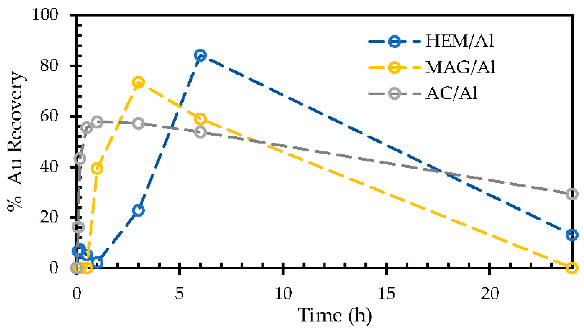
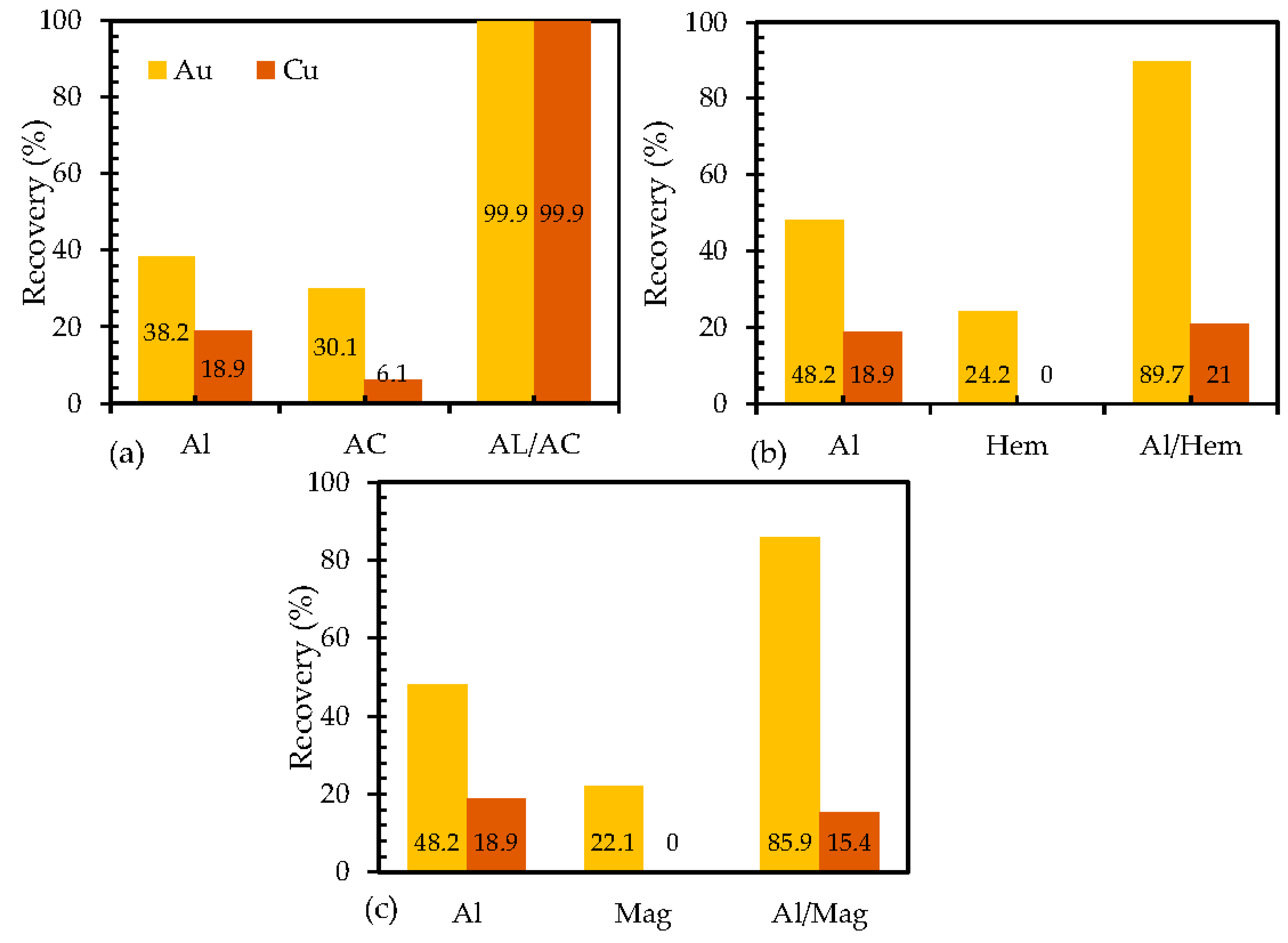
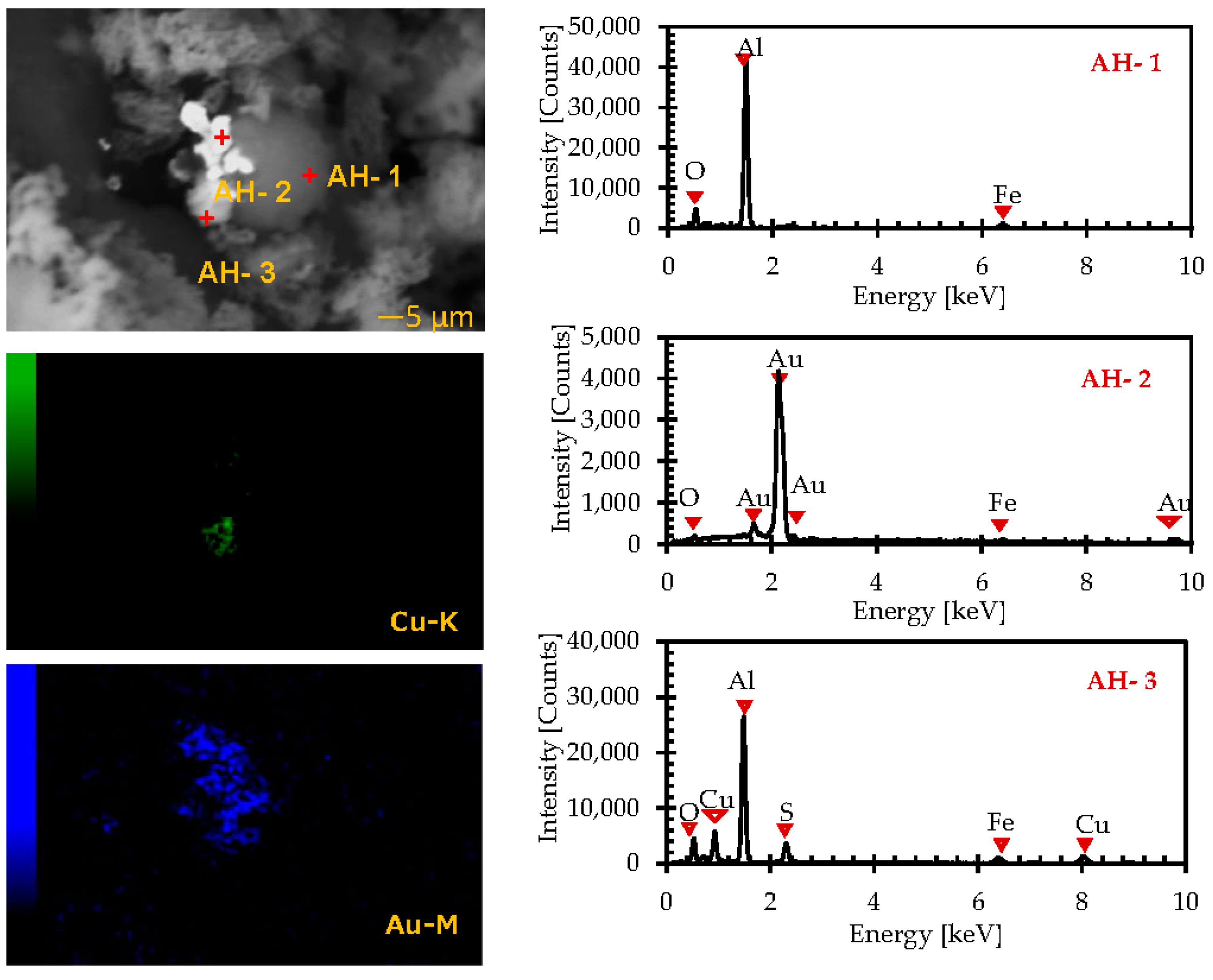
3.1. Recovery of Gold Ions from Ammonium Thiosulfate Solution

Figure 2 shows the percent recovery of gold ions from a gold–copper ammoniacal thiosulfate solution using different galvanic constituents: (a) ZVAl/and or activated carbon (AC), (b) ZVAl/and or hematite (Hem), and (c) ZVAl/ and or magnetite (Mag) in the air, respectively. Figure 2a shows that the gold recovery was negligible when ZVAl was used without electron mediators, such as AC, due to the passivation of the ZVAl surface with aluminum oxide insulator. This passivation layer (aluminum oxide layer) hindered the transfer of electrons from ZVAl to the gold ions in the solution phase, suppressing the electrochemical deposition of gold and copper [15,16,17,18]. Activated carbon had a high specific surface area. It functioned as an adsorbent for the metal ions even without electron donors, such as ZVAl, while the gold and copper recoveries with activated carbon were approx. 24% and 5%, respectively. The low recoveries indicated a limited adsorption of gold and copper complexes from the aqueous phase to activated carbon [16,17,18]. The copper and gold recoveries were also deficient even when activated carbon and ZVAl were used together. As shown in Figure 2b for hematite and Figure 2c for magnetite, it was also found that the gold and copper recoveries were limited when using iron oxides alone or iron oxide and ZVAl together.
The low recoveries of gold at 24 h in the air (Figure 2) may have been due to the dissolution of cemented gold caused by oxidation with O2 [16,17,18]. Figure 3 shows the recoveries of gold using ZVAl and electron mediators as a function of time. It was observed that the gold recoveries increased with time to reach a maximum of 58% at the first 1 h for AC/Al, 75% at 3 h for Fe2O3/Al, and 84% at 6 h for Fe3O4/Al. All the gold recoveries then decreased with time. The increase in the gold recoveries in the initial period suggested that gold was deposited in the presence of both ZVAl and the electron mediators in the short term due to the following equation.
2 A u ( S 2 O 3 ) 2 3 + 6 A l 0 + 6 H + = 2 A u 0 + 8 S 0 + 3 A l 2 O 3 + 3 H 2 O
However, the decrease in the gold recoveries after the maxima, as observed in Figure 3, may have been due to the oxidation of the deposited gold with dissolved oxygen, as shown in Equation (3).
4Au0 + 8(S2O3)2− + O2 + 2H2O = 4Au(S2O3)23− + 4OH
Since the dissolution of gold was significantly affected in the presence of oxygen (O2), the subsequent cementation experiments were conducted without O2 by purging the gold thiosulfate solution with N2 gas for 45 min, as presented in Figure 4a–c, and using ZVAl as an electron donor and various electron mediators. When ZVAI was used without electron mediators, the gold and copper recoveries were slightly improved. The recoveries were 35% for Au and 29% for Cu. These results may have been due to the limited passivation of the Al2O3 layer on the ZVAl surface, allowing for a limited electron transfer from the electron donor (ZVAl) to the metal ions. Insignificant gold and copper recoveries were observed when only electron mediators were used (without ZVAl). The recoveries for Au and Cu were less than 40%, regardless of the electron mediator. This result could indicate that the ability of AC, Fe2O3, and Fe3O4 as adsorbents to the metal ions is limited.
However, when both ZVAl as an electron donor and the electron mediators were used together (binary system), high gold recoveries were observed. The recoveries were approx. 99% using AC/Al, 94% using Fe2O3/Al, and 87% using Fe3O4/Al, respectively. This result may suggest that galvanic couples composed of ZVAl as electron donors and the electron mediators (AC, Fe2O3, and Fe3O4) are remarkably effective in recovering Au from ammonia thiosulfate solutions. A selective recovery of Cu was observed, and the Cu recoveries were 95% using AC/Al, 21% using Fe2O3/Al, and 15% using Fe3O4/Al. These results indicate that Fe2O3/Al and Fe3O4/Al could be used for the selective recovery of gold from copper–ammoniacal thiosulfate solutions.
To investigate the associations of cemented Au and Cu, a morphological analysis of the representative particles on the residues from the cementation experiments was examined in detail using SEM-EDX analysis, as shown in Figure 5, Figure 6 and Figure 7. The results shown in Figure 5 for the residue using AC/Al were consistent with the previously reported results [16,17,18]. In the SEM-BSE image, bright (white) domains (points AC-2 and AC-3) were observed on the surface of the grey particle (point AC-1). The point spectrum data showed that, at the grey particles (point AC-1), firm Al and O peaks were detected with a minor S peak, suggesting that the grey particle was ZVAl with an oxidized surface. In the spectrum at the bright domains (AC-2 and AC-3), the Au and Cu peaks were observed together with the C peak, suggesting that the bright domains corresponded to the Au and Cu deposited on the AC.
The SEM-EDX mapping image confirmed that Au and Cu were always deposited on the AC attached to ZVAl. Figure 6 and Figure 7 show the results of the SEM-EDX analysis for the solid residues obtained in the cementation experiments using Fe2O3/Al and Fe3O4/Al, respectively. The point spectrum and mapping results shown in Figure 6 and Figure 7 suggested that Au was deposited on the iron oxide particles attached to the ZVAl surface. Noticeably, the copper signal intensity ranged from 200 to 6000 cps, as illustrated in Figure 6 AH-3 and Figure 7 AM-3, while the values were higher in the results (1000–31,000 cps) illustrated in Figure 4 AC-2 and AC-3, implying that the copper deposition was limited for the iron oxide/Al system. An analysis of the spectra from 40 different points on illuminated bright particles was conducted. The results showed that the ratio of the gold signal to copper signal was higher for the residues using iron oxide/Al than those using AC/Al. This result agreed with the result illustrated in Figure 4 and confirmed that Au was preferably cemented compared to Cu when iron oxides were used as the electron mediators.

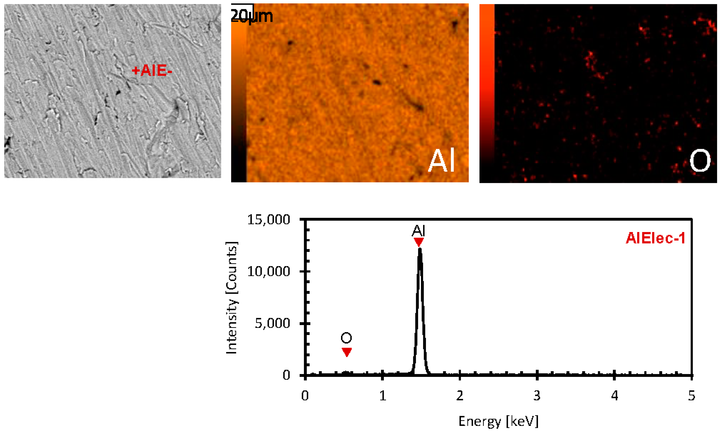
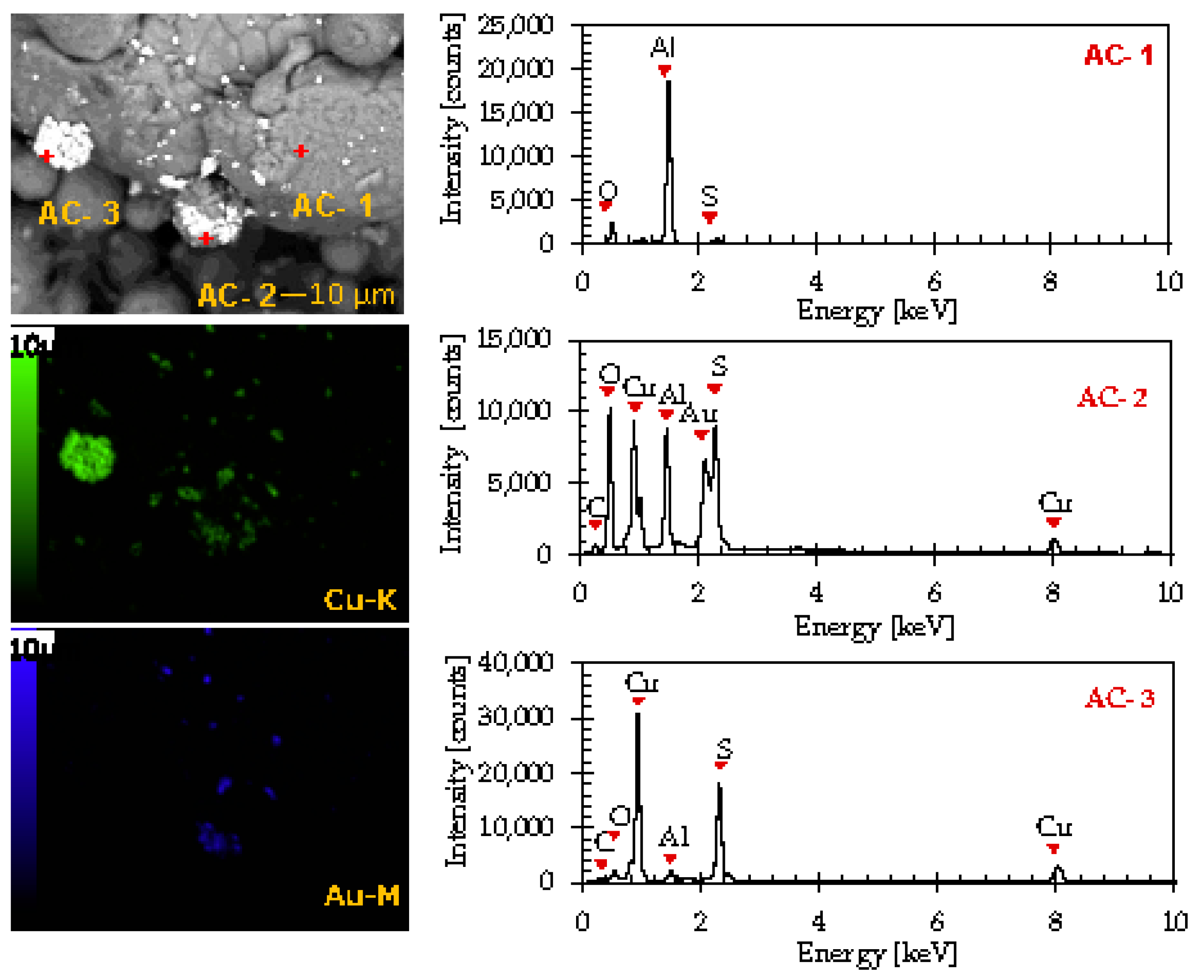
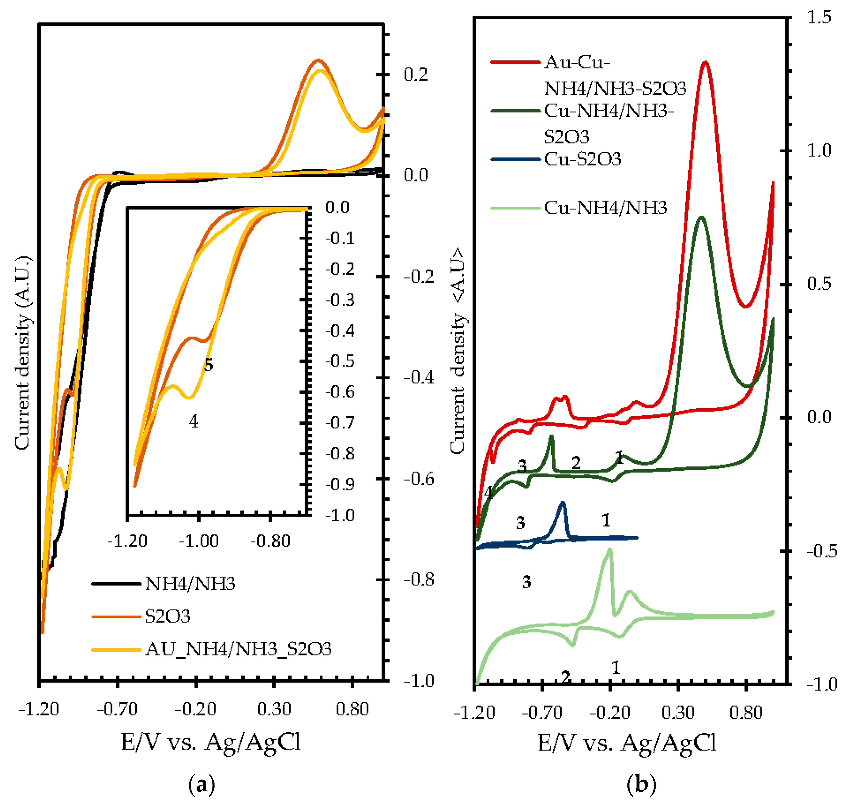
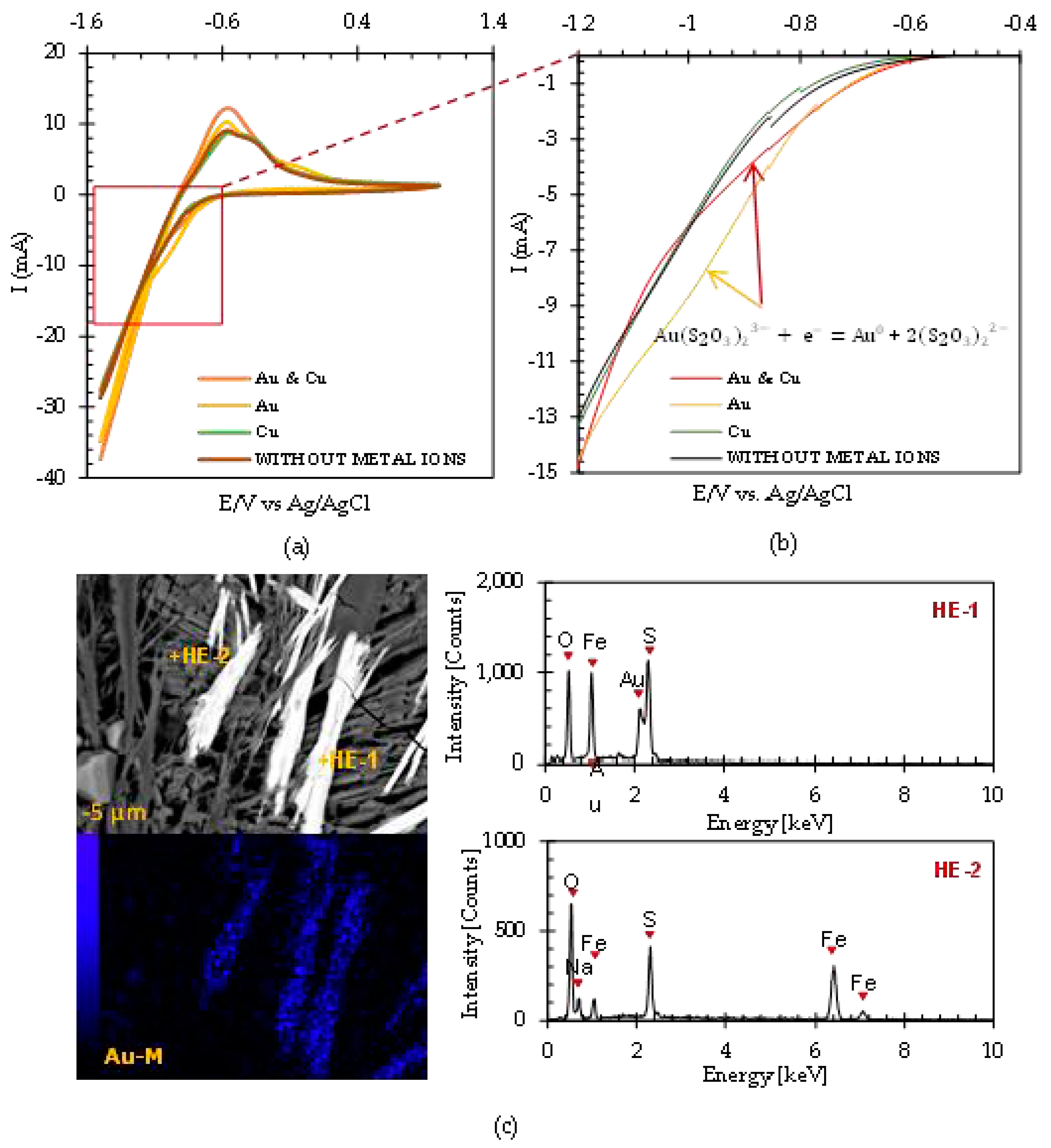
3.2. Electrochemical Properties of the Fe2O3/Al and Fe3O4/Al Electrodes

The cementation of Au and Cu from ammonium thiosulfate solutions was an electrochemical process. When ZVAl was used as an electron donor, the following half-cell reaction of an anode reaction was as follows.
Al = Al3+ + 3e
For the cathodic reactions, the deposition of Cu and Au were assumed to be the following.
Cu(NH3)42+ + 2e = Cu + 4NH3
Au(S2O3)23− + e = Au + 2S2O32−
It is important to note that the anodic reaction was typical for the Cu and Au deposition, while the cathodic reactions differed for Cu and Au. This result suggested that the selective deposition of Au observed in the previous sections was because an Au cathodic reaction was preferred to a Cu reaction when iron oxide was used as an electron mediator. A series of electrochemical experiments were conducted to confirm the results.
To identify the reduction potential of Cu(NH3)42+ and Au(S2O3)23−, cyclic voltammetry was conducted using a Pt working electrode in NH4+/NH3 buffer solutions containing different electrolytes. Figure 8a presents the effects of S2O32− and the gold ions on the electrochemical experiments. In the voltammogram spectra generated using a control (without metal ions) NH4/NH3 buffer solution, the current density was almost zero between −0.7 V and +1.0 V, indicating no electrochemical reaction in the range. However, below −0.7 V, the current decreased with a decreasing electrode potential. This may have been due to a reduction in H2O to form H2 gas.
In the case of S2O32−, a new cathodic current peak appeared at −0.9 V, which was assigned to the reduction in S2O32−. In the anodic region in the cyclic voltammogram with S2O32−, a significant anodic peak was observed around +0.6 V. This peak was observed even when the initial potential scan direction was positive, indicating that the anodic current peak was due to the oxidation of S2O32−.
When the gold ions were added to S2O32−, Au(S2O3)23− was formed. In the experimental results with Au(S2O3)23−, a similar cathodic current peak was observed at −0.9 V. When comparing the cyclic voltammograms, the peak current density was more substantial with Au(S2O3)23− than with S2O32−, implying that both S2O32− and Au+ in Au(S2O3)23− were reduced at almost similar redox potentials.
Figure 8b shows the effects of the cupric species on the cyclic voltammogram. When CuSO4 was added to the NH4/NH3 buffer solution, Cu(NH3)42+ was formed. With Cu(NH3)42+, two cathodic peaks were centered at approximately −0.2 V and −0.5 V, and two anodic peaks appeared. The presence of two cathodic peaks implied that Cu2+ in Cu(NH3)42+ underwent a two-step reduction process. The cathodic peak at −0.2 V corresponded to the reduction in Cu2+ to Cu+, while the peak at −0.5 V corresponded to the reduction in Cu+ to Cu0. Two anodic peaks in the cyclic voltammogram with Cu(NH3)42+ may have been the back reactions of the two-step reduction process. The oxidation of Cu0 to Cu+ and Cu+ to Cu2+ occurred at −0.2 V and 0 V, respectively.
When CuSO4 and S2O32− were added into the NH4/NH3 buffer solution together, two sets of reduction and anodic peaks were observed in the cyclic voltammogram. One was approx. −0.2 V and the other was approx. −0.8 V. The cathodic peak at −0.2 V was also observed in the voltammogram without S2O32−, confirming that this peak was due to the reduction in the Cu(NH3)42+ to Cu(NH3)2+ species.
The peak at −0.8 V was not observed without S2O32− and CuSO4, implying that this cathodic peak reduced the cuprous thiosulfate complexes, such as Cu(S2O3) to Cu0. The cuprous thiosulfate complexes were formed from the amine complex Cu(NH3)2+, which was the reduction product of Cu (NH3)42+. Table 1 summarizes the reduction reactions observed in the cyclic voltammograms, as shown in Figure 8.
Figure 9 and Figure 10 illustrate the voltammogram of the Fe2O3/Al and Fe3O4/Al working electrodes in different electrolyte systems (i.e., 10 mM Cu ions, 10 mM Au ions, 10mM Cu and Au ions, and without metal ions). The cathodic sweep parts were highlighted and projected in the right-side corner of the figures. When comparing the results without metal ions and with only Cu2+, there was no significant difference in the current potential curves, indicating that Cu2+ was not reduced on the iron oxide/Al electrodes. On the other hand, the cathodic current with Au+ was larger than without metal ions, indicating that the gold ions were reduced on the iron oxide/Al electrodes. The cathodic current with the Cu and Au ions was the same as with the electrolyte containing only Au ions, confirming that only Au was reduced on the electrode.
In contrast, Cu2+ was not reduced, i.e., the selective reduction of gold ions occurred on the iron oxide/Al electrodes. The previous paper reported that when an Al electrode was used without an electron mediator, there was no significant reduction current due to the deposition of metal ions, such as Cu and Au [17,18]. Therefore, it can be concluded that the reduction in metal ions occurred only when iron oxides were attached to the surface of the Al electrode. This result suggested that the iron oxides functioned as the electron mediators from Al to the metal ions.
Furthermore, to elucidate the electrochemical behavior of the different improvised electrodes, Figure 11 shows the narrow reduction curves of (a) AC/Al, (b) Fe3O4/Al, (c) Fe2O3/Al, and (d) the comparative reductive scan using the Au and Cu electrolytes of all improvised electrodes (AC/Al (blue line), Fe3O4/Al (red line), Fe2O3/Al (yellow line). It can be observed that when using AC/Al, two shoulder-like peaks were observed at approx. −0.5 V and −1.0 V, while for the iron oxides/Al electrode, only one shoulder-like peak was observed and assigned to the reduction in gold ions. Figure 11d elucidates the comparative narrow reductive scan of all improvised electrode. The results suggest that the cyclic voltammogram agreed with the results during the cementation experiments, where only gold ions could be cemented when using iron oxide in both single and binary systems.
Chronoamperometry was conducted by applying a fixed electrode potential of −1.0 V in the stirred solutions for 60 min to confirm the deposition of Au on the working electrodes. After 60 min, the electrodes were taken out and dried to await SEM-EDX analysis. The elemental mapping and point analysis results are illustrated at the bottom side of Figure 9 and Figure 10. The point analysis results showed that Au peaks were observed along with S peaks at the point HE-1, as shown in Figure 9, and the point ME-1, as shown in Figure 10. At the same point, Fe and O peaks were detected, implying that gold ions were reduced on the surface of the iron oxide particles attached to the Al electrode.
As shown in Figure 12, the gold deposited onto the iron oxide showed a similar morphology with the iron oxide particles (morphology, here, pertains to the shape of the iron oxides). The hematite and deposited gold were in longitudinal orientation (Figure 12A) while the magnetite and gold had an endless array of “nodular-like” particles (Figure 12B). These morphological observation results further supported that the iron oxides were an electron mediator between the electron donor (Al) and the electron acceptor, namely the Au(S2O3)23− ions.
Au(S2O3)23− = Au+ + 2S2O32−
2S2O32− + 6H2O + 8e = 4S0 + 12OH
Au+ + e = Au0
Au(S2O3)23− + 6H2O + 9e = Au0 + 4S0 + 12OH

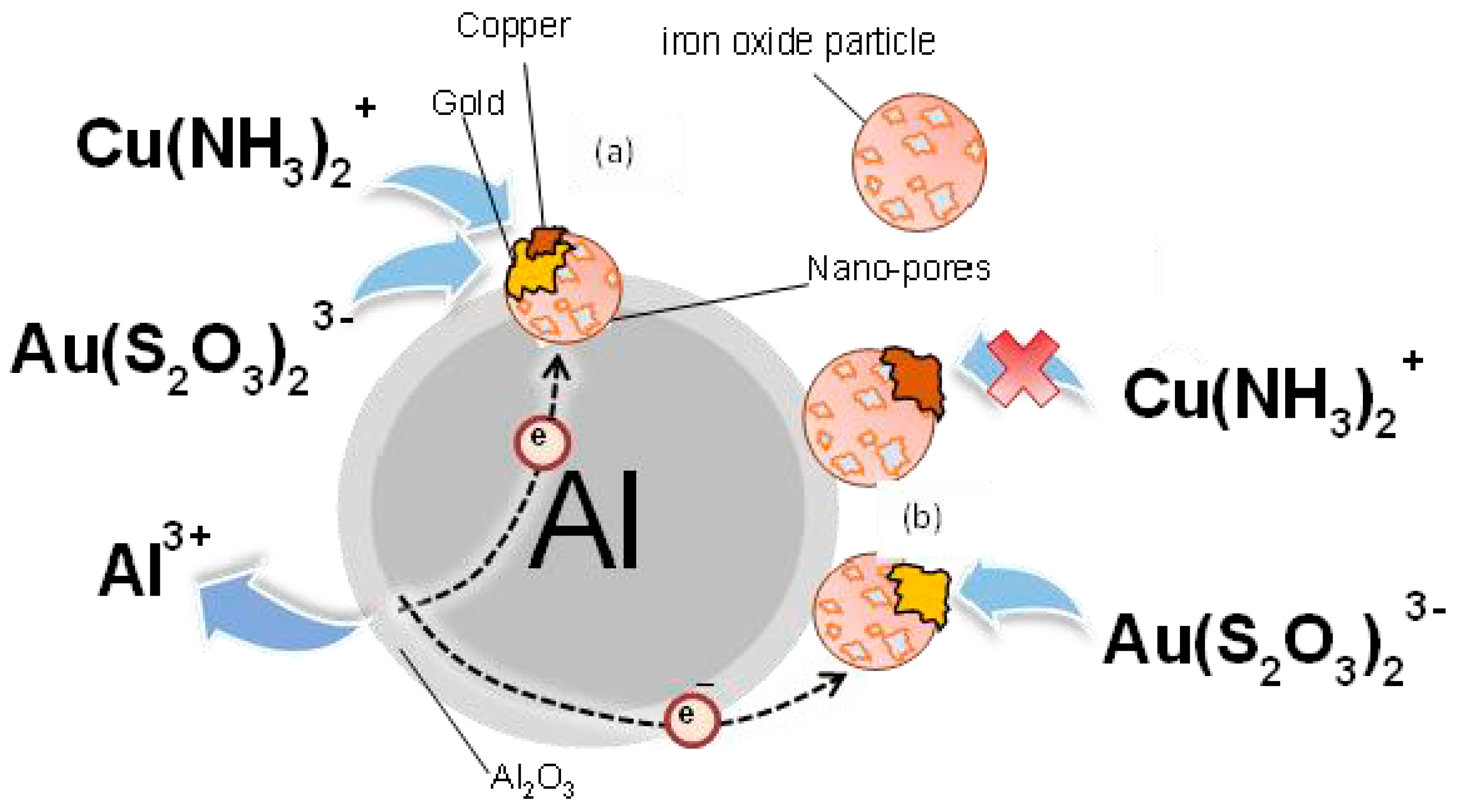
3.3. Proposed Cementation Model

Figure 13 shows the schematic diagram of the proposed cementation model of gold using iron oxides and ZVAl. In this model, ZVAl acted as an electron donor or anode where the anodic dissolution of ZVAl occurred (Equation (4)). An iron oxide particle attached to the ZVAl particle surface acted as an electron mediator or cathode. Electrons from ZVAl passed through the iron oxide to the gold thiosulfate complexes adsorbed on the surface. The cathodic reaction was the cementation (reductive deposition) of Au and S from Au(S2O3)23− (Equation (10)). These ions were assigned as electron acceptors. This mechanism was supported by the electrochemical and surface analysis results presented in Figure 9 and Figure 10.
Several interesting matters that can be observed from the proposed model are presented as follows.
First, for the electron transfer mechanism across the Al2O3 layer between ZVAl and the iron oxide particle, the ZVAl surface was covered with a fragile layer of Al2O3 due to autogenous oxidation. Since Al2O3 is an electric insulating material, a direct current could not pass through this layer. The interpretation of the electron transfer through the insulating Al2O3 layer was expressed via (1) the quantum tunnelling effect [32] and (2) an alternative current transfer through the Al2O3 layer acting as a capacitor [16].
The tunnelling effect interpreted the electron transfer when the Al2O3 layer was fragile, where a thin Al2O3 layer was broken down upon continuous agitation where the particles collided. On the other hand, electron transfer through the Al2O3 capacitor was possible when electrochemical reactions (anodic and cathodic reactions) or physical contact with ZVAl and the iron oxides were dynamically changed over time.
Lastly, the most important issue associated with the proposed model was the selective deposition of gold. Gold was deposited on the iron oxide surface when iron oxides were used as an electron mediator. However, the copper deposition was limited (Figure 6 and Figure 7). Furthermore, the reduction potential of Au(S2O3)23− was much lower than that of Cu(NH3)42+, indicating that from the thermodynamic viewpoint, a reductive deposition of copper was more accessible than gold. This result was confirmed when using activated carbon as an electron mediator where both copper and gold were deposited. These results further suggested that the selective gold deposition was due to the properties of the iron oxide used as the electron mediators, and simple thermodynamic considerations could not interpret the mechanism.
The selective deposition of gold in an ammonia thiosulfate leaching system was significant and industrially attractive since this system required cupric ions as a leaching catalyst, and extremely high concentrations of copper ions coexisted with low concentrations of gold leached from the ores. If the selective deposition of gold were possible, separating gold and copper would not require after the deposition step, and the process would become more straightforward compared to the previous research [16,17,18], where both Cu and Au were cemented using AC as the electron mediator. Thus, understanding the mechanism of selective gold deposition with iron oxide is essential and further studies are needed and may be presented in the following paper.

4. Conclusions

The potential of iron oxides (Fe2O3 and Fe3O4) for use as an electron mediator and their galvanic interactions with zero-valent aluminum for enhancing gold cementation from a gold–copper ammoniacal thiosulfate solution was evaluated. The cementation experiments confirmed that iron oxides could be a potential candidate as an electron mediator. Different from activated carbon (with a 99% Au and Cu recovery) that was previously proposed as an electron mediator, the selective recovery of gold was obtained at approx. 84–89% Au and the Cu recovery was approx. 15–21% Cu when using iron oxides, even when the ammonia thiosulfate leachate contained a high concentration of copper ions. Furthermore, the electrochemical analysis further validated selective cementation. When using iron oxides, the cyclic voltammograms obtained one “shoulder-like” peak centered at −1.0 V for hematite and magnetite, which was assigned to reducing gold ions. Compared to activated carbon, the voltammogram spectra obtained two “shoulder-like” peaks centered at −1.0 V and −0.5 V, which were assigned to gold and copper reduction, respectively.
Lastly, the surface analysis revealed that the morphology of the metal deposited on the surface of the iron oxide/Al electrode after chronoamperometry mimicked the morphology of the iron oxide particles and was assigned only to gold. With these results, a promising effective technology can be used to treat the century-old problem dealing with pyritic-gold bearing ore, where, after the roasting process, gold can be recovered via a thiosulfate leaching–cementation process without using activated carbon as an absorbent. Though this research was focused on the technical feasibility of iron oxides as an electron mediator, the results warrant an in-depth investigation using natural refractory gold ores, which may be presented in the following paper.

Author Contributions

Conceptualization, J.Z., S.J. and N.H.; formal analysis, J.Z., S.J., M.I. and N.H.; investigation, J.Z., Y.E. and N.H.; methodology, J.Z., S.J., A.K., N.O. and I.P.; project administration, N.H.; resources, N.H.; software, J.Z.; supervision, S.J., I.P., M.I., Y.E. and N.H.; validation, J.Z. and N.H.; writing—original draft, J.Z. and N.H.; writing—review and editing, J.Z., S.J. and N.H. All authors have read and agreed to the published version of the manuscript.

Funding

This research received no external funding.

Data Availability Statement

Supporting data can be accessed upon request to the authors.

Conflicts of Interest

The authors declare no conflict of interest.

References

  1. Qin, H.; Guo, X.; Tian, Q.; Zhang, L. Pyrite enhanced chlorination roasting and its efficacy in gold and silver recovery from gold tailing. Sep. Purif. Technol. 2020, 250, 117168. [Google Scholar] [CrossRef]
  2. Qin, H.; Guo, X.; Tian, Q.; Yu, D.; Zhang, L. Recovery of Gold from sulfide refractory gold ore: Oxidation roasting pretreatment and gold extraction. Miner. Eng. 2021, 164, 106822. [Google Scholar] [CrossRef]
  3. Konadu, K.T.; Huddy, R.J.; Harrison, S.T.; Osseo-Asare, K.; Sasaki, K. Sequential pretreatment of double refractory gold ore (DRGO) with a thermophilic iron oxidizing archaeon and fungal crude enzymes. Miner. Eng. 2019, 138, 86–94. [Google Scholar] [CrossRef]
  4. Dong, Z.; Jiang, T.; Xu, B.; Yang, Y.; Li, Q. Recovery of gold from pregnant thiosulfate solution by the resin adsorption technique. Metals 2017, 7, 555. [Google Scholar] [CrossRef] [Green Version]
  5. Nan, X.-Y.; Cai, X.; Jun, K. Pretreatment Process on Refractory Gold Ores with As. ISIJ Int. 2014, 54, 543–547. [Google Scholar] [CrossRef] [Green Version]
  6. Xie, F.; Chen, J.-N.; Wang, J.; Wang, W. Review of gold leaching in thiosulfate-based solutions. Trans. Nonferrous Met. Soc. China 2021, 31, 3506–3529. [Google Scholar] [CrossRef]
  7. Qin, H.; Guo, X.-Y.; Tian, Q.-H.; Zhang, L. Recovery of gold from refractory gold ores: Effect of pyrite on the stability of the thiourea leaching system. Int. J. Miner. Met. Mater. 2021, 28, 956–964. [Google Scholar] [CrossRef]
  8. Sun, C.-B.; Zhang, X.-L.; Kou, J.; Xing, Y. A review of gold extraction using noncyanide lixiviants: Fundamentals, advancements, and challenges toward alkaline sulfur-containing leaching agents. Int. J. Miner. Met. Mater. 2020, 27, 417–431. [Google Scholar] [CrossRef]
  9. Tremblay, L.; Deschênes, G.; Ghali, E.; McMullen, J.; Lanouette, M. Gold recovery from a sulphide bearing gold ore by percolation leaching with thiourea. Int. J. Miner. Process. 1996, 48, 225. [Google Scholar] [CrossRef]
  10. Ma, C.J.; Li, J.Y.; Liu, R.J. A review of thiocyanate hydrometallurgy for the recovery of gold. Appl. Mech. Mater. 2015, 768, 53. [Google Scholar] [CrossRef]
  11. Ahtiainen, R.; Lundström, M. Cyanide-free gold leaching in exceptionally mild chloride solutions. J. Clean. Prod. 2019, 234, 9. [Google Scholar] [CrossRef]
  12. Ahtiainen, R.; Lundström, M.; Liipo, J. Preg-robbing verification and prevention in gold chloride-bromide leaching. Miner. Eng. 2018, 128, 153. [Google Scholar] [CrossRef]
  13. Wang, H.-X.; Sun, C.-B.; Li, S.-Y.; Fu, P.-F.; Song, Y.-G.; Li, L.; Xie, W.-Q. Study on gold concentrate leaching by iodine-iodide. Int. J. Miner. Met. Mater. 2013, 20, 323–328. [Google Scholar] [CrossRef]
  14. Konyratbekova, S.; Baikonurova, A.; Ussoltseva, G.; Erust, C.; Akcil, A. Thermodynamic and kinetic of iodine-iodide leaching in gold hydrometallurgy. Trans. Nonferrous Met. Soc. China 2015, 25, 3774. [Google Scholar] [CrossRef]
  15. Jeon, S.; Bright, S.; Park, I.; Tabelin, C.B.; Ito, M.; Hiroyoshi, N. The effects of Coexisting Copper, Iron, Cobalt, nickel and zinc ions on Gold recovery by enhanced cementation via Galvanic Interactions between zero-valent aluminum and activated carbon in ammonium thiosulfate system. Metals 2021, 11, 1352. [Google Scholar] [CrossRef]
  16. Jeon, S.; Tabelin, C.B.; Takahashi, H.; Park, I.; Ito, M.; Hiroyoshi, N. Enhanced Cementation of gold via galvanic interaction using activated carbon and zero-valent aluminum: A novel Approach to recover gold ions from ammonium thiosulfate medium. Hydrometallurgy 2019, 191, 105165. [Google Scholar] [CrossRef]
  17. Jeon, S.; Bright, S.; Park, I.; Tabelin, C.B.; Ito, M.; Hiroyoshi, N. A simple and efficient recovery technique for gold ions from ammonium thiosulfate medium by galvanic interactions of zero-valent aluminum and activated carbon: A parametric and mechanistic study of cementation. Hydrometallurgy 2021, 208, 105815. [Google Scholar] [CrossRef]
  18. Jeon, S.; Bright, S.; Park, I.; Kuze, A.; Ito, M.; Hiroyoshi, N. A kinetic study on enhanced cementation of gold ions by galvanic interactions between aluminum as an electron donor and activated carbon as an electron mediator in ammonium thiosulfate system. Minerals 2022, 12, 91. [Google Scholar] [CrossRef]
  19. Aylmore, M.; Muir, D. Thiosulfate leaching of gold—A review. Miner. Eng. 2001, 14, 135. [Google Scholar] [CrossRef]
  20. Arima, H.; Fujita, T.; Yen, W. Gold cementation from ammonium thiosulfate solution by zinc, copper, and aluminum powders. Mater. Trans. 2002, 43, 485–493. [Google Scholar] [CrossRef] [Green Version]
  21. Xu, B.; Kong, W.; Li, Q.; Yang, Y.; Jiang, T.; Liu, X. A review of thiosulfate leaching of gold: Focus on thiosulfate consumption and gold recovery from pregnant solution. Met.-Open Access Metall. J. 2017, 7, 222. [Google Scholar] [CrossRef]
  22. Feng, D.; van Deventer, J. Thiosulfate leaching of gold in the presence of pyrite. Hydrometallurgy 2006, 82, 126–132. [Google Scholar] [CrossRef]
  23. Feng, D.; van Deventer, J. Effect of hematite on thiosulphate leaching of gold. Int. J. Miner. Process. 2007, 82, 138–147. [Google Scholar] [CrossRef]
  24. Karavasteva, M. Kinetics and deposit morphology of gold cemented on magnesium, aluminum, zinc, iron, and copper from ammonium thiosulfate-ammonia solutions. Hydrometallurgy 2010, 104, 119–122. [Google Scholar] [CrossRef]
  25. Gallagher, N.P.; Hendrix, J.L.; Milosavljevic, E.G.; Nelson, J.H.; Solujic, L. Affinity of activated carbon towards some gold (I) complexes. Hydrometallurgy 1990, 25, 305–316. [Google Scholar] [CrossRef]
  26. Choi, S.; Jeon, S.; Park, I.; Ito, M.; Hiroyoshi, N. Addition of Fe3O4 as electron mediator for enhanced cementation of cd2+ and Zn2+ on aluminum powder from sulfate solutions and magnetic separation to concentrate cemented metals from cementation products. J. Environ. Chem. Eng. 2021, 9, 106699. [Google Scholar] [CrossRef]
  27. Hu, G.; Dam-Johansen, K.; Wedel, S.; Hansen, J.P. Decomposition and Oxidation of Pyrite. Prog. Energy Combust. Sci. 2006, 32, 295–314. [Google Scholar] [CrossRef]
  28. IAlp; Celep, O.; Paktunç, D.; Thibault, Y. Influence of potassium hydroxide pretreatment on the extraction of gold and silver from a refractory ore. Hydrometallurgy 2014, 146, 64. [Google Scholar] [CrossRef]
  29. Balarini, J.C.; Polli, L.d.O.; Miranda, T.L.S.; de Castro, R.M.Z.; Salum, A. Importance of roasted sulphide concentrates characterization in the hydrometallurgical extraction of zinc. Miner. Eng. 2008, 21, 100–110. [Google Scholar] [CrossRef]
  30. Fu, P.; Li, Z.; Feng, J.; Bian, Z. Recovery of Gold and Iron from Cyanide Tailings with a Combined Direct Reduction Roasting and Leaching Process. Metals 2018, 8, 561. [Google Scholar] [CrossRef] [Green Version]
  31. Tabelin, C.B.; Veerawattananun, S.; Ito, M.; Hiroyoshi, N.; Igarashi, T. Pyrite oxidation in the presence of hematite and alumina: II. Effects on the cathodic and anodic half-cell reactions. Sci. Total Environ. 2017, 581–582, 126–135. [Google Scholar] [CrossRef] [PubMed]
  32. Ke, B.; Li, Y.; Chen, J.; Zhao, C.; Chen, Y. DFT study on the galvanic interaction between pyrite (100) and galena (100) surfaces. Appl. Surf. Sci. 2016, 367, 270–276. [Google Scholar] [CrossRef]
Figure 1. Backscattered electron photomicrograph with elemental mapping and point EDS analysis of the improvised aluminum electrode.
Metals 13 01289 g001
Figure 2. Percent recovery of gold and copper from the different galvanic constituents in an air atmosphere using (a) activated carbon (AC) and/or ZVAl, (b) hematite (Hem) and/or ZVAl, and (c) magnetite (Mag) and/or ZVAl.
Metals 13 01289 g002
Figure 3. Percent recovery of gold with respect to time using ZVAl and different electron mediators.
Metals 13 01289 g003
Figure 4. Percent recovery of gold and copper from different galvanic constituents in a nitrogen atmosphere using (a) activated carbon (AC) and/or ZVAl, (b) hematite (Hem) and/or ZVAl, and (c) magnetite (Mag) and/or ZVAl.
Metals 13 01289 g004
Figure 5. Backscattered electron photomicrograph using an energy-dispersive point analysis with elemental mapping of the leach residue using Al and AC galvanic systems.
Metals 13 01289 g005
Figure 6. Backscattered electron photomicrograph using an energy-dispersive point analysis with elemental mapping of the leach residue using Al and hematite galvanic systems.
Metals 13 01289 g006
Figure 7. Backscattered electron photomicrograph using an energy-dispersive point analysis with elemental mapping of the leach residue using Al and Magnetite galvanic system.
Metals 13 01289 g007
Figure 8. Voltammogram characterization of (a) NH4/NH3, S2O3, and Au-NH4/NH3_S2O3; and (b) Au-CU-NH4/NH3-S2O3, Cu-NH4/NH3, Cu-NH4/NH3-S2O3 and Cu-S2O3.
Metals 13 01289 g008
Figure 9. Cyclic voltammogram of the Fe2O3/Al electrode at different electrolytes: (a) wide scan; (b) narrow reduction voltammogram; (c) backscattered electron photomicrograph with elemental mapping and a pointed analysis of the Cu–Au electrolytes.
Metals 13 01289 g009
Figure 10. Cyclic voltammogram of the Fe3O4/Al electrode at different electrolytes: (a) wide scan; (b) narrow reduction voltammogram; (c) backscatter electron photomicrograph with elemental mapping and a pointed analysis of the Cu–Au electrolytes.
Metals 13 01289 g010
Figure 11. Cyclic voltammogram narrow reduction curve: (a) AC/Al, (b) Fe3O4/Al, (c) Fe2O3/Al, and (d) a narrow reductive scan of all the improvised electrodes at the Cu and Au electrolytes.
Metals 13 01289 g011
Figure 12. Backscattered electron photomicrograph of (A) hematite particles (left) and hematite with Au (right), and (B) magnetite particles (left) and magnetite with Au (right).
Metals 13 01289 g012
Figure 13. Schematic diagram of the proposed galvanic electron transfer mechanism of iron oxide and zero-valent aluminum. (a) Direct contact on the porosity within the Al–oxyhydroxide layer and (b) direct transfer through the Al–oxyhydroxide layer.
Metals 13 01289 g013
Table 1. Summary of the reduction reactions observed in the cyclic voltammograms using Pt as a working electrode, as shown in Figure 8.
Assigned Reductions ReactionsPotential (V)
C u ( N H 3 ) 4 2 + + e C u ( N H 3 ) 2 + + 2 N H 3 −0.2
C u ( N H 3 ) 4 + + e C u 0 + 4 N H 3 −0.5
C u ( S 2 O 3 ) 2 3 + e C u 0 + 2 S 2 O 3 2 −0.8
2S2O32− + 6 H 2 O + 8e → 4S0 + 12OH−0.9
A u ( S 2 O 3 ) 2 3 + 6 H 2 O + 9 e A u 0 + 4 S 0 + 12 O H −1.0
Disclaimer/Publisher’s Note: The statements, opinions and data contained in all publications are solely those of the individual author(s) and contributor(s) and not of MDPI and/or the editor(s). MDPI and/or the editor(s) disclaim responsibility for any injury to people or property resulting from any ideas, methods, instructions or products referred to in the content.

