
Cyclic Oxidation Kinetics and Thermal Stress Evolution of TiAl Alloys at High Temperature
by
Shiwei Tian
1,2,*,
Tengkun Zhang
1,
Shangwu Zeng
3,
Yefei Zhang
1,
Dejun Song
2,
Yulai Chen
1,
Qiang Kang
4 and
Haitao Jiang
1 1
National Engineering Research Center for Advanced Rolling and Intelligent Manufacturing, University of Science and Technology Beijing, Beijing 100083, China
2
Research Laboratory VIII, Luoyang Ship Material Research Institute, Luoyang 471026, China
3
Advisory Planning and Strategic Intelligence Group, China Metallurgical Information and Standardization Institute, Beijing 100730, China
4
Ansteel Beijing Research Institute Co., Ltd., Beijing 102211, China
*
Author to whom correspondence should be addressed.
Metals 2024, 14(1), 28; https://doi.org/10.3390/met14010028
Submission received: 21 November 2023
/
Revised: 20 December 2023
/
Accepted: 22 December 2023
/
Published: 26 December 2023
(This article belongs to the Special Issue Microalloying in Ferrous and Non-ferrous Alloys)
Abstract
:The oxidation resistance of TiAl alloys is crucial for their commercial application. In this paper, a cyclic oxidation test with stable air circulation was designed to investigate the cyclic oxidation behavior of the TNM alloy and 4822 alloy at 800 °C and to analyze the phase, morphology, and thermal stress evolution of the oxide layer. The oxidation weight gain curves of both alloys are found to be in parabolic form, and the oxidation reaction orders of the TNM alloy and 4822 alloy are 2.374 and 1.838, respectively. The Nb and Mo elements enhance the antioxidant performance of the TNM alloy by inhibiting the dissolution and diffusion of oxygen, Ti, and Al atoms in the TiAl alloy. The thermal stress evolution of the two alloys during the heating and cooling phases of the cyclic oxidation process are calculated separately, and it is found that the thermal stresses in the TNM alloy are smaller than those in the 4822 alloy, while the maximum thermal stresses appear at the oxide/substrate interface rather than inside the oxide scale, which quantitatively explains the oxidation peeling resistance of the two alloys.
1. Introduction
TiAl alloys have low density, high specific strength, and good high-temperature mechanical properties [1,2]. They are considered to be the best candidates for high-temperature structural materials in the range of 650–900 °C, and have shown great application potential in aviation, aerospace, automotive, and other fields. The GEnxTM engine uses Ti–48Al–2Cr–2Nb (4822 alloy) instead of the nickel-based superalloy to manufacture the last two stages of low-pressure turbine blades, and the weight of a single engine is reduced by about 72.5 kg [3]. To improve the high-temperature properties and expand the application range of TiAl alloys, third-generation TiAl alloys with high Nb and Mo addition have been developed in recent years, which have higher strength and oxidation resistance. The Ti–43.5Al–4Nb–1Mo–0.1B alloy (as the Nb and Mo represent the decisive alloying elements, this TiAl alloy family has been named the TNM alloys) proposed by Clemens et al. is one of the third-generation TiAl alloys [4,5,6,7].
In addition to its mechanical properties, another problem to be solved is the oxidation of TiAl alloys during service. When the temperature is higher than 750 °C, the oxidation resistance of TiAl alloys decreases significantly [8]. The oxidation resistance of TiAl alloys is not only related to the oxidation temperature and time, but also to the content of the alloying elements, oxidation atmosphere, microstructure, surface roughness, and applied load. Yoshihara [9] found that Nb substitutes for Ti in rutile as a cation with valence 5, and the growth rate of rutile in Ti–Nb alloys, is remarkably reduced by Nb substitution of Ti, which helps to improve the oxidation resistance of TiAl alloys. Lee [10] studied the effect of element addition on TiAl alloys, and found that Nb, W, and Si are beneficial, while Cr and V are harmful to the oxidation resistance of TiAl alloys. Grip [11] found that the oxidation resistance in the resistance sintering method was better than that of the pressureless sintering method, because the former promoted the formation of dense Al2O3. Su [12] prepared the 4822 alloy by vacuum hot pressing sintering and found that the increase in the surface porosity led to an increase in the oxidation weight gain. Yang [13] compared the oxidation resistance of TiAl alloys with different microstructures and found that the submicron (ω0 + γ) has better oxidation resistance than the nearly lamellar structure. In addition, the oxidation resistance of TiAl alloys can be improved by pre-oxidation, surface treatment, and coating protection [14]. Typical coatings include the Ti–Si coating, Al–Si coating, and NiCoCrAlY coating [15,16,17]. The surface modification includes halogen element treatment, surface nitriding [18,19], and so on.
At present, TiAl alloys are mainly initially used in low-pressure turbine blades. Due to the increased weight and risk of failure, the use of protective coatings is not the best strategy. At this time, more attention is paid to the oxidation resistance and spalling resistance of the TiAl alloy itself. In the TNM alloy, due to the addition of Nb and Mo elements, the microstructure and the chemical composition of each phase in the TiAl alloy change, which affects the oxidation resistance of the TiAl alloy. At the same time, it is noted that most of the previous studies were focused on isothermal oxidation [20], and most of the experimental conditions were based on static air. However, in actual service, TiAl alloys often undergo cyclic temperature changes and have continuous contact with oxygen. In the process of repeated heating and cooling, it is easy to generate large thermal stress on the surface of the TiAl alloy, causing the oxide scale on the surface to fall off, which is fatal to the service of the TiAl alloy. To ensure the normal use of TiAl alloys under harsh conditions, it is necessary to form a highly stable protective oxide scale to prevent the oxide scale from cracking during long-term oxidation [21]. Due to the inconsistent thermal expansion coefficients between the oxide scale and the substrate, or between different oxide layers, compressive stress or tensile stress will be generated during cooling or heating. The adhesion between the oxide scale and the substrate is also related to the thickness of the oxide scale and the interface defects. Once the stress exceeds the binding force between the oxide scale and the substrate, the oxide scale is prone to crack or even fall off. At present, the research on the exfoliation of oxide scale on the surface of the TiAl alloy mostly depends on qualitative analysis and lacks quantitative characterization. Therefore, this paper compares the very promising TNM alloy with the commercial 4822 alloy, designs a cyclic oxidation test with stable air circulation, analyzes the difference in oxidation resistance between the two TiAl alloys, and quantitatively analyzes the effect of thermal stress on oxide layer cracking.
2. Materials and Methods
The materials used in this paper are Ti–44.5Al–3.8Nb–1.0Mo–0.3Si–0.1B (at. %, this alloy is slightly different from the TNM alloy compositions proposed by Clemens, mainly in regard to the differences in Si and Al content) and commercial forged Ti–48Al–2Cr–2Nb (at. %) alloys. The TNM alloy ingot was melted in a vacuum suspension furnace, then hot isostatically pressed at 1250 °C at 175 MPa, and finally rolled at 1200 °C with a deformation of 60%. The oxidation experiments were conducted in a box-type resistance furnace (SX-5-12, made by Zhongkeyiqi, Beijing, China) at a temperature of 800 °C. Normally, oxidation experiments are carried out in resistance furnaces that are not charged with air (known as still air). With the growth in the oxidation time, the oxygen content inside the furnace is gradually consumed and declines. Therefore, in the later stages of oxidation, oxygen content variations can interfere with the experimental results. To avoid the above situation, an air compressor was added to the resistance furnace to ensure the airflow and oxygen content in the furnace (note: there was a small round hole of Φ6 mm at the front and back of the resistance furnace).
The size of the TiAl specimen was 10 × 10 × 5 mm3; all six surfaces were mechanically polished with a roughness of 32 ± 3 μm (Rmax). A total of twenty TNM alloys and twenty 4822 alloys were used. Every 4 alloys were placed in a symmetrical position in the crucible to ensure consistent experimental conditions. The airflow and pressure were 50 mL/min and 0.2 MPa, respectively. The TNM and 4822 alloy specimens were simultaneously placed in a crucible with an inner diameter of 80 mm, a height of 20 mm, and a wall thickness of 4 mm. Put the crucible into the furnace at 800 °C, and the crucible was removed and cooled for 10 min after oxidizing for 60 min, which is an oxidation cycle (shown in Figure 1). To determine the heating and cooling speed of the specimen, the temperature at different moments was measured by a temperature tester, and the test results are shown in Figure 1. The specimen rapidly rose above 700 °C during the heating process. In the temperature range of 700 °C to 800 °C, the heating rate was reduced, after about 10 min or so the specimen reached 800 °C, and the furnace atmosphere temperature was the same. The temperature after 10 min of blast cooling was 65.7 °C, and the average cooling rate was 1.2 °C/s.
The specimens were weighed every 10 cycles; four specimens were weighed at each weighing point and the average oxidized weight gains were calculated. The thermal expansion curves of the TiAl alloys were completed using a DIL805A quenching expansion instrument (made by BÄHR Thermoanalyse GmbH, Hüllhorst, Germany). X-ray diffraction (XRD, made by Bruker, Billerica, MA, USA) was performed to characterize the phases of the specimens. The target material was Cu, the scanning speed was 10°/min, the step size was 0.02°, and the scanning range was 10~90°. The results were analyzed using the MDI jade software (Jade 5.0 version). A Quanta 450FEG field emission environmental scanning electron microscope from FEI, USA, was used for the oxide observation of the specimens. The surface observation of the oxidized specimens did not require any treatment, while the cross-section observation required nickel plating, cold mounting, and low-speed grinding and polishing.
3. Results and Discussion
3.1. Oxidation Kinetics Analysis
Figure 2 shows the cyclic oxidation kinetics curves of the TNM alloy and 4822 alloy. The oxidation kinetic curves of the two alloys are basically parabolic types. That is, the oxidized weight gain increases rapidly at the beginning of oxidation and slows down as the oxidation time increases. The weight gain of the 4822 alloy is greater than that of the TNM alloy, and the curve of the 4822 alloy appears to fluctuate after cyclic oxidation for 300 cycles, and the fluctuation becomes more obvious as the number of oxidation cycles increases.
The oxidation kinetics of TiAl alloys can be expressed by Equation (1) [22]:
where the is the oxidation weight gain per unit area (mg/cm2), K is the oxidation reaction rate constant (mg/cm2·h−1), t is the oxidation time (h), and n is the reaction order.
If n ≤ 1, the oxidation kinetics curve is linear, that is, the oxidation weight gain is proportional to the oxidation time, and the oxidation resistance of the oxide film is poor. When 1 < n ≤ 2, the oxidation law is between a straight line and a parabola, the thickness of the oxide film does not grow proportionally, but increases to a certain extent. When n > 2, the oxide film becomes dense and the diffusion coefficient in the film decreases. In the process of cyclic oxidation, there is no clear formula to quantify the oxidation resistance. In a sense, the heating and cooling stages of cyclic heat treatment are the accumulation of a series of micro-isothermal oxidation processes. In addition, most of the time, cyclic oxidation occurs in the isothermal oxidation stage. Besides, the experimental conditions of the TNM and 4822 alloys are the same, and it is acceptable to use the isothermal oxidation formula to evaluate their oxidation resistance at the same time. It is calculated that the n value of the 4822 alloy is 1.838, and the n value of the TNM alloy is 2.374 (higher than 2), indicating that the cyclic oxidation resistance of the TNM alloy is better than that of the 4822 alloy.
3.2. Phase and Morphology Analysis of Oxidation Surface
Figure 3 shows the XRD patterns of the two alloys after different oxidation cycles. The oxidation products of the two alloys are mainly composed of A12O3 and TiO2. For the TNM alloy, the peak intensity of TiO2 at 2θ = 27.66° and 2θ = 57.38° increases with the increase in the oxidation cycles. This shows that the oxidation product content increases as the oxidation time increases. For the 4822 alloy, the peak intensity of the oxidation products of the 4822 alloy decreases when the cyclic oxidation reaches 400 times, and then increases again when the oxidation reaches 710 times. This is closely related to the peeling of the oxide scale and second oxidation. When the oxide peels off, the substrate is exposed, the diffraction peaks of the substrate are enhanced, and the diffraction peaks of the oxides are weakened. With the increase in the number of oxidation cycles, the exposed substrate undergoes secondary oxidation, which is manifested by the re-enhancement of the oxide diffraction peaks.
Figure 4 shows the macroscopic morphologies of the alloys after different oxidation cycles. After 300 oxidation cycles, the edges of the 4822 alloy begin to flake off, and the inner brown oxide layer is shown here. After 400 oxidation cycles, multiple flaking can be observed on the 4822 alloy. At the same time, the initial peeling area is re-oxidized, and the color changes from brown to gray. After 520 cycles of oxidation, the flaking area has penetrated the entire surface of the 4822 alloy. The flaking moment corresponds with the fluctuation in the oxidation kinetics curves in Figure 2. As for the TNM alloy, after 710 oxidation cycles, there is only one small spall on the edge of the alloy. Besides, it is noted that the TNM alloy shows different color changes at different oxidation cycles. From the macroscopic morphology, it can be concluded that the anti-stripping ability of the oxidation scale on the TNM alloy is greater than that of the 4822 alloy. Strictly speaking, the peeling ability of the alloy can be better evaluated by weighing the peeled oxide scale. In this paper, because the anti-stripping ability of the 4822 and TNM alloys are too different, we compare and analyze them directly with macro photos, which is not very rigorous.
Figure 5 shows the surface morphologies of the two alloys after different oxidation cycles. Many granular TiO2 cluster oxides grow on the surface of TNM alloy, and there is a fine Al2O3 layer underneath (Figure 5a). The oxidation scale on the 4822 alloy is composed of prismatic TiO2 oxides, and there are many gaps between these TiO2 oxides. As can be seen from Figure 5a–d, the oxide size of the two alloys increases with the increasing oxidation cycles. Besides, under the same cycles, the oxide size of the 4822 alloy is larger than that of the TNM alloy.
Figure 6 shows the peeling area of the two alloys. After 710 oxidation cycles, only a small area of the oxide scale on the TNM alloy peels off, while the oxide scale on the 4822 alloy first exhibits peeling and then second peeling (Figure 6b). The peeling areas of the two alloys are similar in morphology. There are many pits left by the flaking of the oxide scale, and the oxides are very fine. Although the oxide scale is composed of multiple layers, it is not absolutely flat between the layers or between the oxide layer and the substrate, and the size of the oxide particles in each layer is not uniform, so many pits appear after the oxide scale peels off. After the oxide scale flakes off, leaving the substrate or the thin oxide film exposed to the air, the elements of the substrate diffuse through the thin oxide film to the surface and react with oxygen to regenerate fine oxides. Whether from a macroscopic or microscopic observation of the surface morphology of the oxides, it is known that the anti-stripping ability of the TNM alloy is better than that of the 4822 alloy.
3.3. Cross-Sectional Morphology of Oxide Scale
Figure 7 shows the cross-sectional morphologies of the oxide scales on the two alloys after 300, 520, and 710 oxidation cycles. The oxide scale thickness of the two alloys increases with the increase in the oxidation cycles. At the same number of oxidation cycles, the oxide scale thickness on the 4822 alloy is larger than that of the TNM alloy, which is consistent with the oxidation kinetics curves. The oxide scale on the TNM alloy remains intact after 520 oxidation cycles, and microcracks appear between the oxide scale and the substrate after 710 oxidation cycles (Figure 7e). As for the 4822 alloy, not only do obvious cracks appear between the oxide scale and the substrate, but the cracks have also expanded into the TiO2/Al2O3 mixed layers after 300 oxidation cycles (Figure 7b). After 520 oxidation cycles, the oxide scale is separated from the substrate and transversely fractured (Figure 7d). After 710 oxidation cycles, the first peeling of the oxide scale and the second growth in the oxide scale can be observed (Figure 7f). After 710 oxidation cycles, the outermost layer of the TNM alloy has formed continuous TiO2, which is consistent with the observation results on the surface morphology. At the same time, there is a certain amount of Al2O3 in the inner layer of the TiO2.
Figure 8 shows the element distribution along the oxide scale to the substrate. It can be observed that for both alloys, the outermost layer shows the peak of the Ti element, representing the outermost layer is TiO2, and the peak of the TiO2 on the outer side of the TNM alloy is weak, indicating that the growth in the TiO2 on the TNM alloy is inhibited to a certain extent. On the inside of the TiO2, the peak of Al can be seen, representing Al2O3. In Figure 8a, it can be seen that there is a peak of N near the substrate. It is generally believed that TiN or Ti2AlN is formed here [23,24]. As it is close to the substrate, it is not shown in the XRD patterns. It can also be noted that there are Nb and Mo enrichment zones near the TiN/Ti2AlN. Previous studies have shown that Nb-rich and Mo-rich zones can effectively hinder the internal diffusion of oxygen atoms and the external diffusion of Ti and Al atoms [25]. In the range of 6~10μm in Figure 8b, obvious alternating peaks of Ti and Al can be observed, which means that there is mixed growth in the TiO2 and Al2O3 in the 4822 alloy.
How to inhibit the formation and growth of TiO2 and promote the formation of continuous dense Al2O3 is the key to improving the oxidation resistance of TiAl alloys [26]. In the TiAl alloy, because the oxidation kinetics of the Ti and Al elements to form TiO2 and Al2O3 are similar, a continuous Al2O3 film cannot be formed in the air atmosphere, but TiO2 and Al2O3 are formed at the same time [27]. Since the self-diffusion coefficient of the Ti element in the TiAl alloy is much larger than that of the Al element, it is beneficial to the outer diffusion of Ti to form the outermost TiO2 layer. According to the cross-sectional morphology analysis, it can be seen that the growth rate of the outermost TiO2 layer in the TNM alloy is slower than that of the 4822 alloy. In addition, the Al2O3 inside the TNM alloy is denser than that of the 4822 alloy.
Firstly, studies have shown that Nb and Mo elements can effectively reduce the solid solubility of oxygen atoms in the TiAl alloy substrate [25]. Secondly, high valence elements Nb and Mo can replace or partially replace Ti4+ in TiO2. Nb and Mo ions are doped in the TiO2 lattice, which reduces the concentration of oxygen vacancies and defects in TiO2, thereby reducing the internal diffusion rate of O and hindering the internal oxidation [28]. Besides, Nb and Mo are enriched at the interface between the substrate and the oxide scale, which hinders the outward diffusion of Ti and Al atoms and inhibits the overgrowth of the outermost TiO2 layer. In addition, the TiAl alloy with the addition of Nb and Mo has stronger anti-stripping ability, which will be explained in the next section. The above factors lead to better oxidation resistance of the TNM alloy than that of the 4822 alloy.
3.4. Stress-Induced Cracking Mechanism in the Cyclic Oxidation Process
The oxidation resistance of TiAl alloys depends not only on whether a dense and protective oxide scale can be formed on the surface, but also on the anti-stripping ability of the oxide scale. During the cyclic oxidation process, due to the difference in thermal expansion coefficients of the oxides and the substrate, the temperature change will cause stress between the oxide scale and the substrate, or between different oxide layers. The calculation method is as follows [22]:
In the formula, σox is the stress endured by the oxides (MPa), and Eox and EM, respectively, represent the elastic modulus of the oxide and the matrix or two adjacent oxides. Moreover, αox and αM, respectively, represent the thermal expansion coefficients of the oxide and the matrix or two adjacent oxides. Additionally, hox and hM, respectively, represent the thickness of the oxide and the matrix or two adjacent oxides. Then, Ta and Tb represent the start and end temperature, respectively. The v is Poisson’s ratio, and vox and vM, respectively, represent the Poisson’s ratio of the oxide and the matrix or two adjacent oxides.
When Ta = Tb (constant temperature oxidation) or αox = αM, σox = 0, there is no stress between the oxide and the substrate or between two adjacent oxides. When αox < αM and Ta > Tb (cooling stage), σox < 0, meaning that the oxide is under compressive stress. When αox < αM and Ta < Tb (heating stage), σox > 0, indicating that the oxide is under tensile stress. Since the thickness of the oxide scale is much smaller than that of the substrate (hox << hM), Equation (2) can be simplified as:
Figure 9 shows the thermal expansion curves of the two alloys. During the heating stage, the temperature ranges in which the expansion of the TNM alloy and 4822 alloy increase linearly are RT~500 °C and RT~700 °C, respectively. The temperatures of 500 °C and 700 °C are the starting points for the reduction in the expansion coefficients of the TNM alloy and 4822 alloy, respectively. The decreasing trend in the TNM alloy curve is gentle, while that of the 4822 alloy is relatively severe, especially between 700 °C and 800 °C. The thermal expansion coefficients of each temperature interval are calculated from the thermal expansion curves, as shown in Table 1. From Table 1, it can be seen that the thermal expansion coefficients of the TNM alloy are lower than that of the 4822 alloy. According to the references, the elastic modulus of TiO2, Al2O3, and TiN are 282 GPa, 400 GPa, and 248 GPa, respectively, and Poisson’s ratios are 0.368, 0.205, and 0.270 [29,30,31], respectively. Substituting these data into Equation (3), the stress between the oxide scale and the substrate or between the oxide layers during the heating/cooling stage can be obtained, as shown in Table 2.
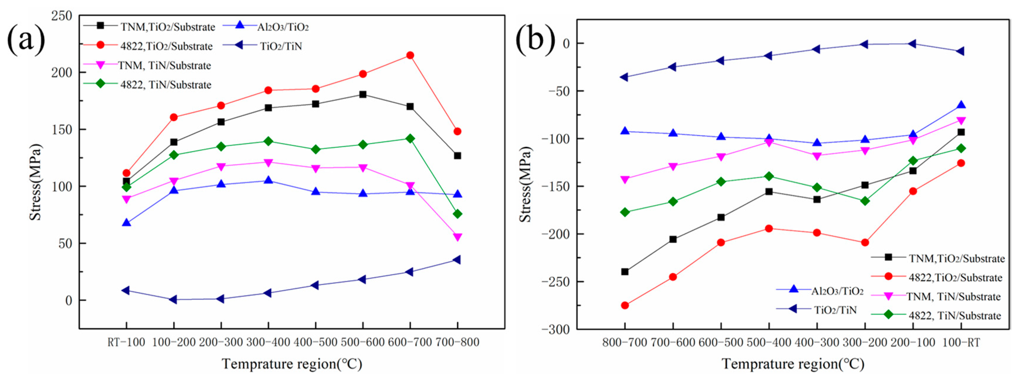
Figure 10 shows the stress between the oxide scale and the substrate, or between the oxide layers, at each temperature region during the cyclic oxidation process. When there is no TiN layer between the oxide scale and the substrate, the TiO2 is next to the substrate, and the tensile stress of the substrate on the TiO2 in the TNM alloy increases gradually with the temperature increase from RT to 600 °C. It reaches the maximum value of 180.55 MPa in the 500~600 °C region, while the stress of the 4822 alloy reaches the maximum value of 214.87 MPa in the 600~700 °C region.
In regard to the TNM alloy, the tensile stress values of the substrate acting on the TiO2 at all temperature regions are smaller than that of the 4822 alloy, and the maximum stress difference is 45.0 MPa in the 600~700 °C region. During the cooling process, the compressive stress of the substrate acting on the TiO2 in the two alloys decreases with the decrease in temperature. Meanwhile, the compressive stress of the 4822 alloy is significantly greater than that of the TNM alloy, and the maximum compressive stress difference is −60.27 MPa in the 300~200 °C region. The tensile/compressive stress value of TiO2 acting on Al2O3 has no obvious change trend, and the stress value is relatively small. However, it can be inferred from Equation (2) that as the oxidation time increases, and the TiO2 layer becomes thicker, the stress of TiO2 on Al2O3 will increase.
When an obvious TiN layer is formed between the oxide scale and the substrate, the TiN is subjected to stress from the substrate, which is similar to that of TiO2, except that the stress value is smaller. This is because the coefficient of thermal expansion of TiN is higher than that of TiO2 and closer to the substrate. Besides, the interaction force between TiN and the TNM alloy substrate is still smaller than that between TiN and the 4822 alloy substrate. Since the thermal expansion coefficients of TiO2 and TiN are relatively close, the stress between them is very small.
It seems that the stress generated at each stage (every 100 °C as an interval) is not particularly large. However, as the heating and cooling time is short, the accumulated stress in a short period of time can reach up to 1000 MPa. In addition, the cyclic oxidation needs to undergo many times of alternating heating and cooling, so that the oxide scale is repeatedly subjected to tensile/compressive stress. When the stress exceeds the bonding force, microcracks and peeling will occur. From the point of view of the stress value, it does not matter whether TiO2 or TiN is subjected to the greatest stress by the substrate. Thus, cracks should be generated between the TiO2 or TiN layer and the substrate, not between the oxide layers, which is consistent with the cracks in Figure 7. Therefore, the substrate is exposed after the oxide scale is peeled off.
The reason why the oxidation resistance of the TNM alloy is better than that of the 4822 alloy is not only that the oxide scale is less stressed by the substrate and the stress changes smoothly, but it is also related to the structure of the oxide scale. The oxide scale on the TNM alloy has an obvious layered structure, while the oxide scale on the 4822 alloy has a mixed structure of TiO2 and Al2O3. This mixed structure cannot effectively prevent the internal diffusion of oxygen, making the oxide scale thicker. Moreover, this structure puts the entire oxide scale in a larger stress state during the heating and cooling stages of the cycle oxidation process.
4. Conclusions
The behavior of cyclic high-temperature oxidation for two alloys, TNM and 4822, was investigated under constant air flow conditions to compare the oxidation kinetics, oxidation morphology, and thermal stress distribution, and the following main conclusions were revealed:
- In the flowing air atmosphere, the oxidation weight gain curves of the two TiAl alloys at 800 °C show a parabolic type. The oxide scale is mainly composed of TiO2 and Al2O3, and the TNM alloy shows better anti-oxidation peeling performance.
- The Nb and Mo elements hinder the dissolution of oxygen atoms in the TiAl alloy substrate and promote the formation of continuous dense Al2O3. In addition, the Nb and Mo elements are enriched at the substrate/oxide interface, which hinders the external diffusion of Ti and Al atoms and the internal diffusion of oxygen atoms, thus improving the oxidation resistance of the TNM alloy.
- It is found that the thermal stress of the TNM alloy during heating and cooling is less than that of the 4822 alloy. It is also found that the thermal stress between the oxide scale and the substrate is greater than that inside the oxide scale, which explains the reason why the oxide scale peeling mainly occurs at the interface between the oxide scale and the substrate.
Author Contributions
Conceptualization, S.Z. and Y.C.; methodology, D.S.; software, Q.K. and H.J.; validation, T.Z.; formal analysis, Q.K.; investigation, S.T., T.Z. and S.Z.; resources, Y.Z. and H.J.; data curation, T.Z. and D.S.; writing—original draft preparation, S.T. and S.Z.; writing—review and editing, Y.C. and H.J.; visualization, Y.Z. and H.J.; project administration, Y.C.; funding acquisition, S.T. and D.S. All authors have read and agreed to the published version of the manuscript.
Funding
This research was funded by National Natural Science Foundation of China, grant number No. 52201035.
Data Availability Statement
The data generated and/or analyzed during the current study are not publicly available for legal/ethical reasons, but are available from the corresponding author on reasonable request.
Acknowledgments
We also thank Zhiqian Liao, Chong Li from the Luoyang Ship Material Research Institute and Yongjun Zhang from the University of Science and Technology Beijing for their contributions and efforts in the experiments, analyses and discussions in this study.
Conflicts of Interest
Author Qiang Kang was employed by the company Ansteel Beijing Research Institute Co., Ltd. The remaining authors declare that the research was conducted in the absence of any commercial or financial relationships that could be construed as a potential conflict of interest.
References
- Yang, Y.; Liang, Y.; Li, C.; Lin, J. Microstructure and Mechanical Properties of TiAl Matrix Composites Reinforced by Carbides. Metals 2022, 12, 790. [Google Scholar] [CrossRef]
- Jiang, H.; Zhang, G.; Guo, W.; Tian, S.; Lin, H.; Zeng, S. Deformation Behavior of Ti2AlNb—Based Alloy during Dynamic Compression. Adv. Eng. Mater. 2018, 20, 1800281. [Google Scholar] [CrossRef]
- Kim, Y.W.; Kim, S.L. Advances in gamma alloy materials–processes–application technology: Successes, dilemmas, and future. JOM 2018, 70, 553–560. [Google Scholar] [CrossRef]
- Clemens, H.; Mayer, S. Design, processing, microstructure, properties, and applications of advanced intermetallic TiAl alloys. Adv. Eng. Mater. 2013, 15, 191–215. [Google Scholar] [CrossRef]
- Clemens, H.; Boeck, B.; Wallgram, W.; Schmoelzer, T.; Droessler, L.M.; Zickler, G.A.; Leitner, H.; Otto, A. Experimental Studies and Thermodynamic Simulations of Phase Transformations in Ti-(41-45) Al-4Nb-1Mo-0.1 B Alloys; MRS Online Proceedings Library (OPL): Warrendale, PA, USA, 2008; p. 1128. [Google Scholar]
- Clemens, H.; Wallgram, W.; Kremmer, S.; Güther, V.; Otto, A.; Bartels, A. Design of novel β-solidifying TiAl alloys with adjustable β/B2-phase fraction and excellent hot-workability. Adv. Eng. Mater. 2008, 10, 707–713. [Google Scholar] [CrossRef]
- Wallgram, W.; Clemens, H.; Kremmer, S.; Otto, A.; Güther, V. Hot-Die Forging of a β-Stabilized γ-TiAl Based Alloy; MRS Online Proceedings Library (OPL): Warrendale, PA, USA, 2008; p. 1128. [Google Scholar]
- Bik, M.; Galetz, M.; Mengis, L.; White, E.; Wieczorek, W.; Łyszczarz, K.; Mroczka, K.; Marchewka, J.; Sitarz, M. Oxidation behaviour of uncoated and PDC-SiAlOC glass-coated TiAl at 750° C in dry and humid air. Appl. Surf. Sci. 2023, 632, 157601. [Google Scholar] [CrossRef]
- Yoshihara, M.; Miura, K. Effects of Nb addition on oxidation behavior of TiAl. Intermetallics 1995, 3, 357–363. [Google Scholar] [CrossRef]
- Lee, D. Effect of Cr, Nb, Mn, V, W and Si on high temperature oxidation of TiAl alloys. Met. Mater. Int. 2005, 11, 141–147. [Google Scholar] [CrossRef]
- Garip, Y. Investigation of isothermal oxidation performance of TiAl alloys sintered by different processing methods. Intermetallics 2020, 127, 106985. [Google Scholar] [CrossRef]
- Su, Z.; Song, X.; Duan, Z.; Chen, H.; Huang, H.; Liu, Y.; Han, Y. High Temperature Oxidation Behaviors of Powder Metallurgical γ-TiAl Based Alloys: Effects of Surface Defects on Morphology of the Oxide Scale. Metals 2022, 12, 1743. [Google Scholar] [CrossRef]
- Yang, G.; Bai, W.; Han, S.; Wang, Y.; Cheng, L.; Zuo, J.; Kim, S.W. An enhanced oxidation resistance in Ti-40Al-8Nb alloys with submicron (ω0+ γ) microstructure: A comparative study. Corros. Sci. 2023, 213, 110989. [Google Scholar] [CrossRef]
- Swadźba, R.; Laska, N.; Bauer, P.P.; Krztoń, H. Effect of pre-oxidation on cyclic oxidation resistance of γ-TiAl at 900° C. Corros. Sci. 2020, 177, 108985. [Google Scholar] [CrossRef]
- Crespo-Villegas, J.; Cavarroc, M.; Knittel, S.; Martinu, L.; Klemberg-Sapieha, J.E. Protective TixSiy coatings for enhanced oxidation resistance of the ɣ-TiAl alloy at 900° C. Surf. Coat. Technol. 2022, 430, 127963. [Google Scholar] [CrossRef]
- Yang, L.; Gao, F.; Zhou, Z.; Jia, Y.; Du, Y.; Wang, J.; Qiao, Y.; Zhu, S.; Wang, F. Oxidation behavior of the AlN coatings on the TiAl alloy at 900° C. Corros. Sci. 2023, 211, 110891. [Google Scholar] [CrossRef]
- Swadźba, R.; Swadźba, L.; Mendala, B.; Bauer, P.P.; Laska, N.; Schulz, U. Microstructure and cyclic oxidation resistance of Si-aluminide coatings on γ-TiAl at 850° C. Surf. Coat. Technol. 2020, 403, 126361. [Google Scholar] [CrossRef]
- Donchev, A.; Gleeson, B.; Schütze, M. Thermodynamic considerations of the beneficial effect of halogens on the oxidation resistance of TiAl-based alloys. Intermetallics 2003, 11, 387–398. [Google Scholar] [CrossRef]
- Magnan, J.; Weatherly, G.C.; Cheynet, M.C. The nitriding behavior of Ti-Al alloys at 1000° C. Metall. Mater. Trans. A 1999, 30, 19–29. [Google Scholar] [CrossRef]
- Narayana, P.L.; Kim, J.H.; Yun, D.W.; Kim, S.E.; Reddy, N.S.; Yeom, J.T.; Seo, D.; Hong, J.K. High temperature isothermal oxidation behavior of electron beam melted multi-phase γ-TiAl alloy. Intermetallics 2022, 141, 107424. [Google Scholar] [CrossRef]
- Rahmel, A.; Schütze, M.; Quadakkers, W.J. Fundamentals of TiAl oxidation—A critical review. Mater. Corros. 1995, 46, 271–285. [Google Scholar] [CrossRef]
- Young, D.J. High Temperature Oxidation and Corrosion of Metals; Elsevier: Amsterdam, The Netherlands, 2008. [Google Scholar]
- Lu, W.; Chen, C.L.; Wang, F.H.; Lin, J.P.; Chen, G.L.; He, L.L. Phase transformation in the nitride layer during the oxidation of TiAl-based alloys. Scr. Mater. 2007, 56, 773–776. [Google Scholar] [CrossRef]
- Zhao, B.; Wu, J.; Sun, J.; Tu, B.; Wang, F. Effect of nitridation on the oxidation behavior of TiAl-based intermetallic alloys. Intermetallics 2001, 9, 697–703. [Google Scholar] [CrossRef]
- Tian, S.; He, A.; Liu, J. Oxidation resistance of TiAl alloy improved by hot-pack rolling and cyclic heat treatment. Mater. Charact. 2021, 178, 111196. [Google Scholar]
- Zhao, P.X.; Li, X.B.; Xing, W.W.; Bo, C.H.; Kui, L.I. Cyclic oxidation behavior of Nb/Mn/Si alloying beta-gamma TiAl alloys. Trans. Nonferrous Met. Soc. China 2023, 33, 128–140. [Google Scholar] [CrossRef]
- Lin, X.J.; Huang, H.J.; Yuan, X.G.; Wang, Y.X.; Zheng, B.W.; Zuo, X.J.; Zhou, G. High-temperature oxidation behavior of a cast Ti-47.5 Al-2.5 V-1.0 Cr-0.2 Zr alloy. China Foundry 2022, 19, 443–454. [Google Scholar] [CrossRef]
- Xu, Z.; Li, Q.; Gao, S.; Shang, J. Synthesis and characterization of niobium-doped TiO2 nanotube arrays by anodization of Ti–20Nb alloys. J. Mater. Sci. Technol. 2012, 28, 865–870. [Google Scholar] [CrossRef]
- Anada, H.; Shida, Y. Effect of Mo addition on the oxidation behavior of TiAl intermetallic compound. Mater. Trans. JIM 1995, 36, 533–539. [Google Scholar] [CrossRef]
- Jiang, S.S.; Zhang, K.F. Study on controlling thermal expansion coefficient of ZrO2–TiO2 ceramic die for superplastic blow-forming high accuracy Ti-6Al-4V component. Mater. Des. 2009, 30, 3904–3907. [Google Scholar] [CrossRef]
- Yao, H.; Ouyang, L.; Ching, W. Ab Initio Calculation of Elastic Constants of Ceramic Crystals. J. Am. Ceram. Soc. 2007, 90, 3194–3204. [Google Scholar] [CrossRef]
Figure 1.
Heating and cooling temperature curves during cyclic oxidation.
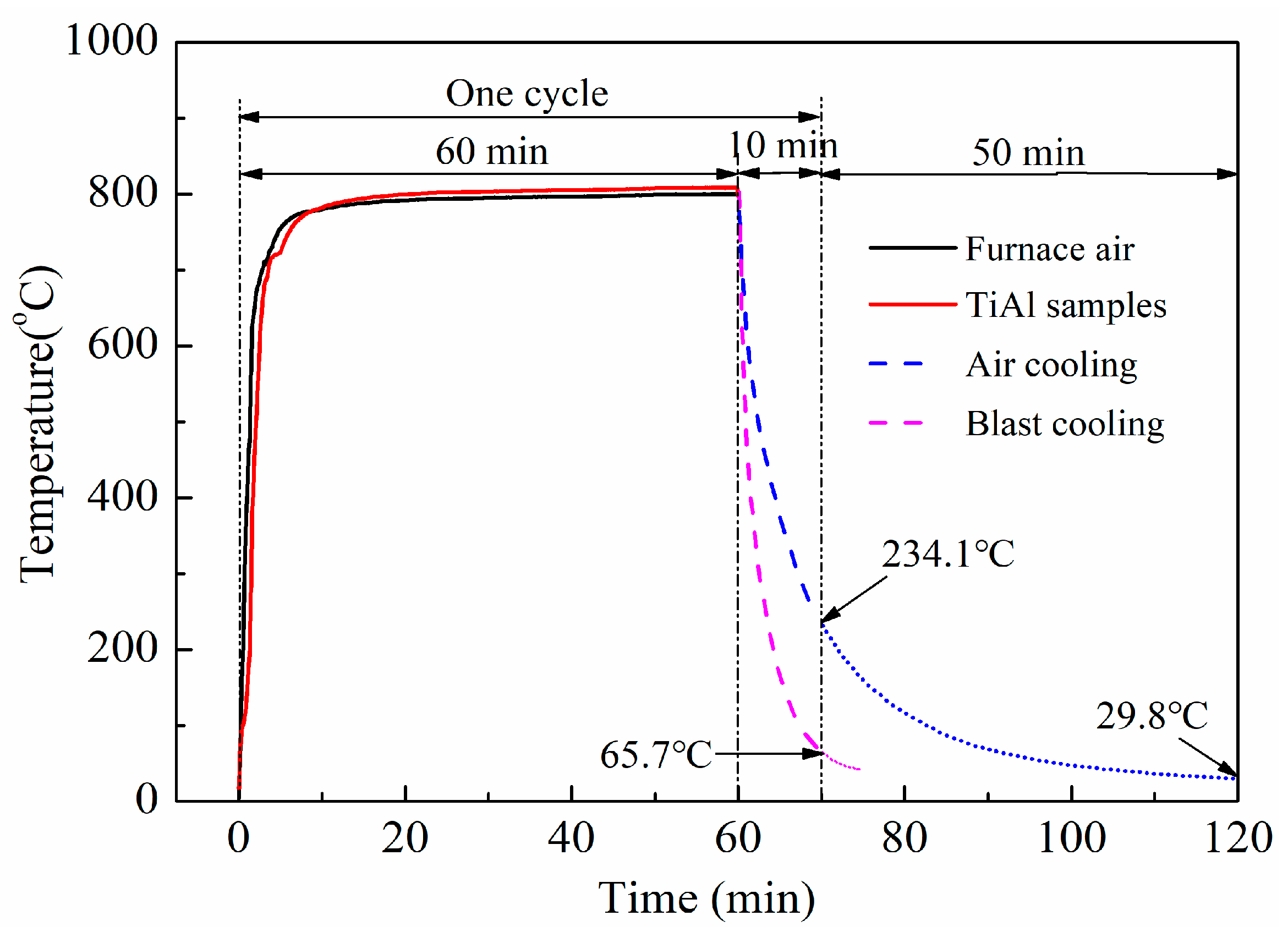
Figure 2.
Oxidation kinetics curves of TNM and 4822 alloys.

Figure 3.
XRD patterns of TiAl alloys after cyclic oxidation: (a) TNM alloy and (b) 4822 alloy.
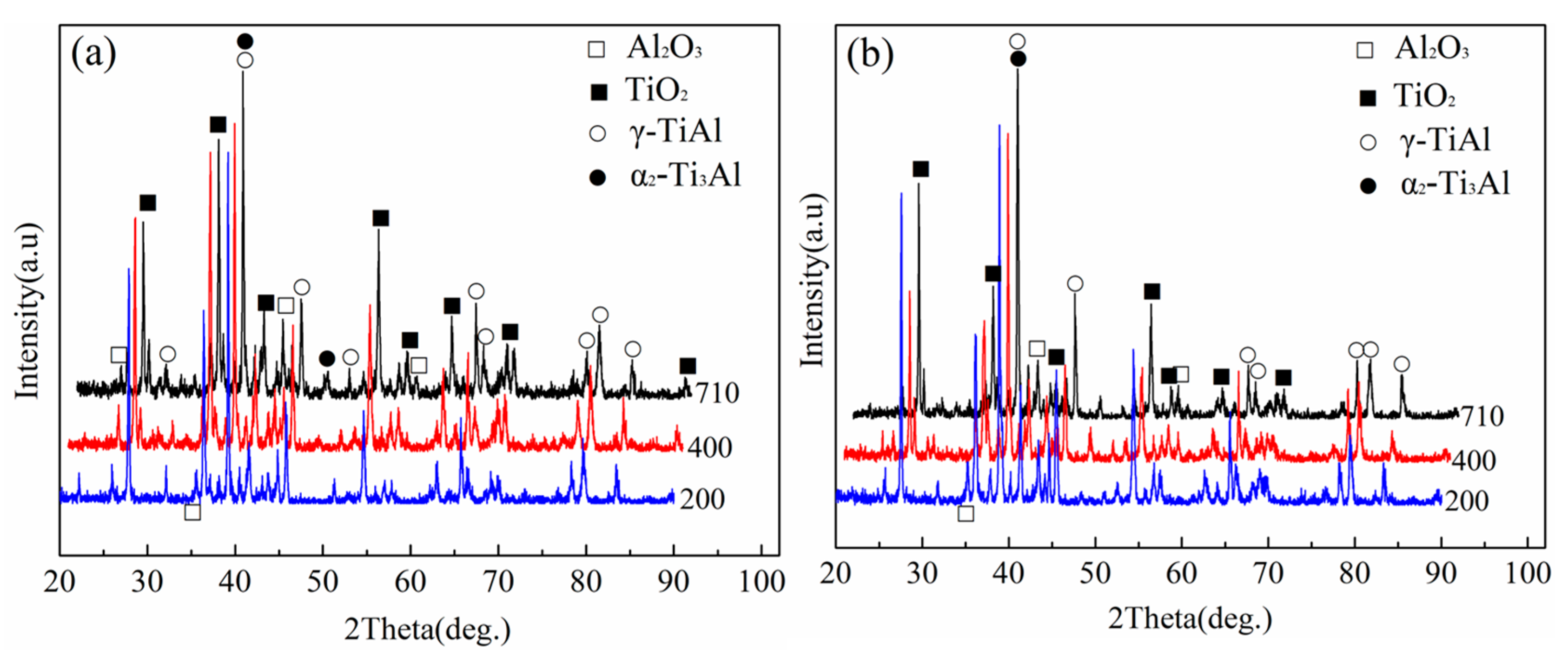
Figure 4.
Macroscopic morphology of TiAl alloys after different oxidation cycles: (a) 300 cycles, (b) 400 cycles, (c) 520 cycles, (d) 710 cycles.
Figure 4.
Macroscopic morphology of TiAl alloys after different oxidation cycles: (a) 300 cycles, (b) 400 cycles, (c) 520 cycles, (d) 710 cycles.
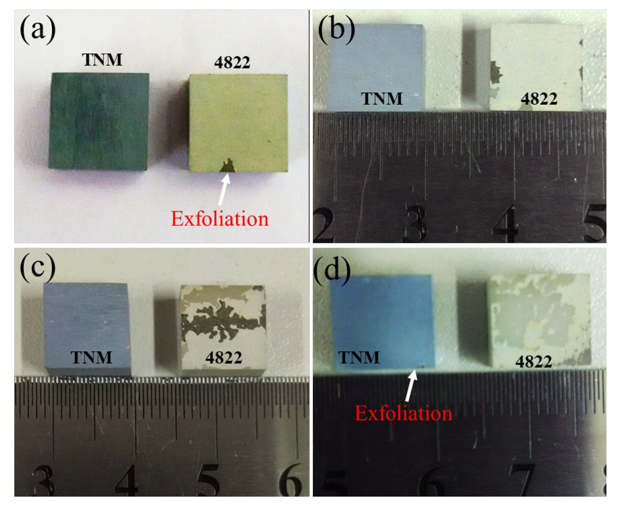
Figure 5.
Surface oxide morphology of TiAl alloys after different oxidation cycles: (a) TNM, 300 cycles; (b) 4822, 300 cycles; (c) TNM, 520 cycles; (d) 4822, 520 cycles.
Figure 5.
Surface oxide morphology of TiAl alloys after different oxidation cycles: (a) TNM, 300 cycles; (b) 4822, 300 cycles; (c) TNM, 520 cycles; (d) 4822, 520 cycles.

Figure 6.
Surface oxide morphology of TiAl alloys after 710 oxidation cycles: (a) TNM, (a1) peeling area and (a2) outermost oxidation scale; (b) 4822, (b1) secondary peeling and (b2) first peeling.
Figure 6.
Surface oxide morphology of TiAl alloys after 710 oxidation cycles: (a) TNM, (a1) peeling area and (a2) outermost oxidation scale; (b) 4822, (b1) secondary peeling and (b2) first peeling.

Figure 7.
Cross-sectional morphologies of TiAl alloys after different oxidation cycles: (a) TNM, 300 cycles; (b) 4822, 300 cycles; (c) TNM, 520 cycles; (d) 4822, 520 cycles; (e) TNM, 710 cycles; (f) 4822, 710 cycles.
Figure 7.
Cross-sectional morphologies of TiAl alloys after different oxidation cycles: (a) TNM, 300 cycles; (b) 4822, 300 cycles; (c) TNM, 520 cycles; (d) 4822, 520 cycles; (e) TNM, 710 cycles; (f) 4822, 710 cycles.
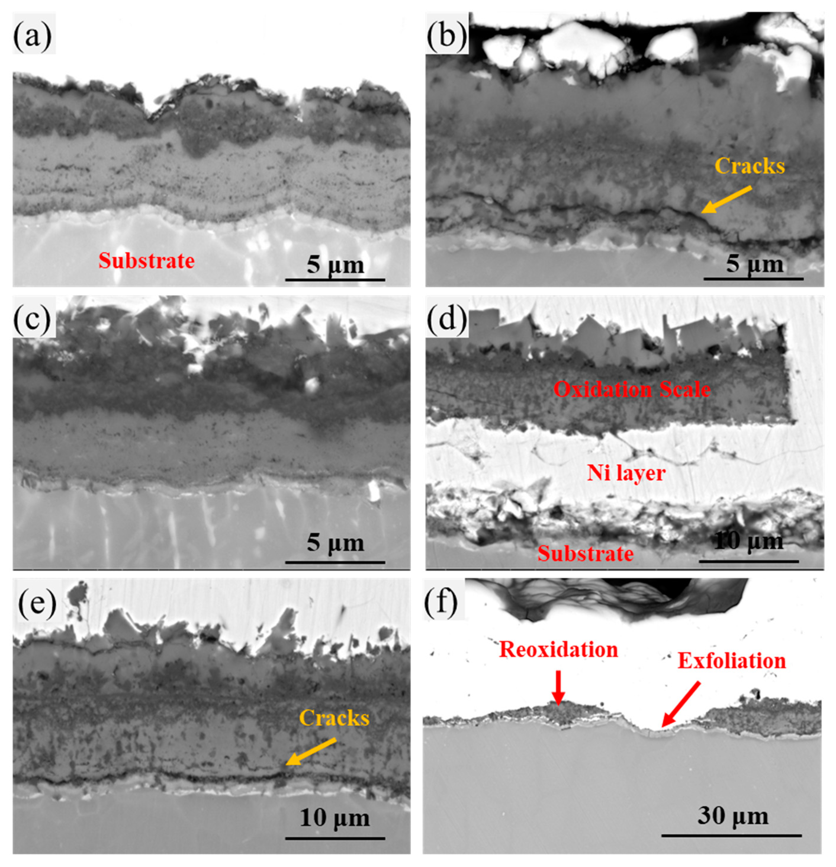
Figure 8.
Distribution of elements along the cross section after 300 oxidation cycles: (a) TNM and (b) 4822.
Figure 8.
Distribution of elements along the cross section after 300 oxidation cycles: (a) TNM and (b) 4822.
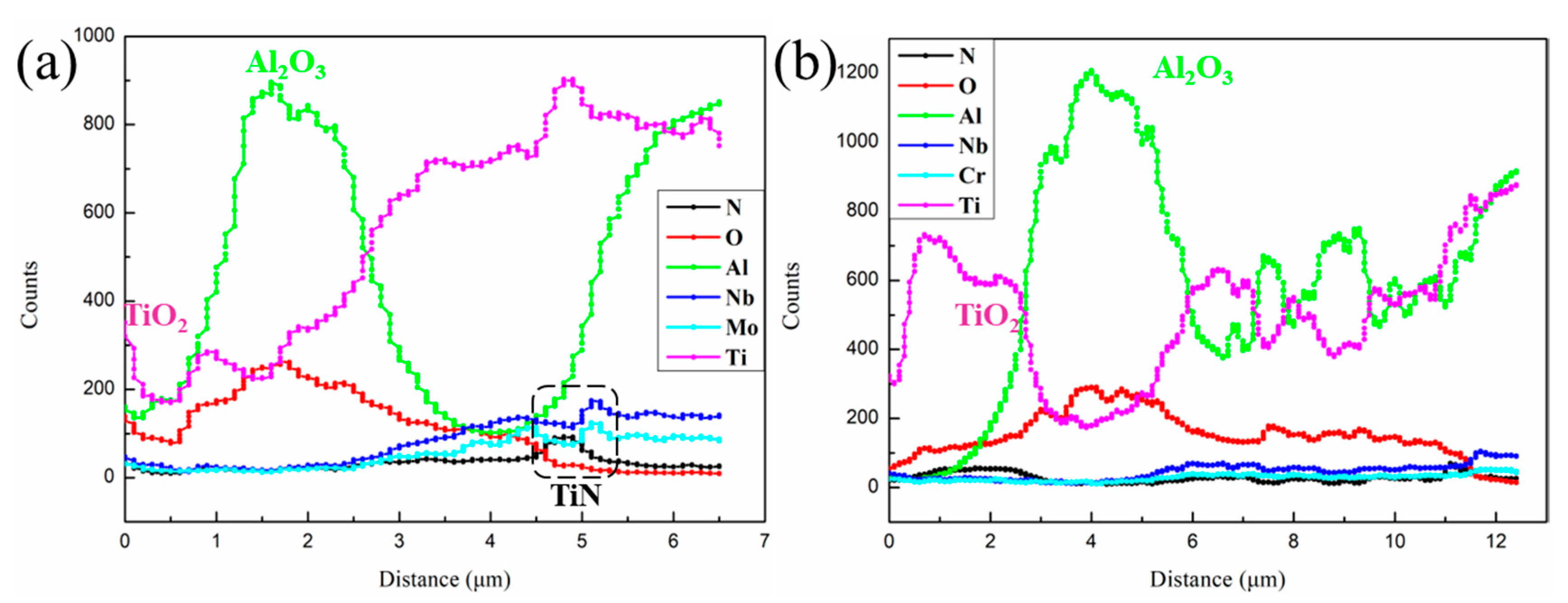
Figure 9.
The expansion curves of TiAl alloy in the heating and cooling stages.

Figure 10.
Thermal stress during (a) heating stage and (b) cooling stage of TiAl alloys.

Table 1.
Thermal expansion coefficient (×10−6/°C).
| Materials | TNM | 4822 | Al2O3 | TiO2 | TiN | ||
|---|---|---|---|---|---|---|---|
| Temperature | Heating | Cooling | Heating | Cooling | — | — | — |
| RT | — | — | — | — | — | — | — |
| 100 °C | 11.47 | 11.22 | 11.69 | 12.27 | 6.50 | 8.20 | 7.80 |
| 200 °C | 11.54 | 11.43 | 12.03 | 11.91 | 6.70 | 8.43 | 8.45 |
| 300 °C | 12.16 | 12.00 | 12.49 | 13.35 | 6.83 | 8.66 | 8.70 |
| 400 °C | 12.67 | 12.56 | 13.02 | 13.35 | 7.00 | 8.89 | 9.10 |
| 500 °C | 12.97 | 12.60 | 13.27 | 13.47 | 7.40 | 9.11 | 9.55 |
| 600 °C | 13.39 | 13.44 | 13.79 | 14.03 | 7.66 | 9.34 | 9.95 |
| 700 °C | 13.38 | 14.18 | 14.39 | 15.06 | 7.86 | 9.57 | 10.40 |
| 800 °C | 12.63 | 15.16 | 13.11 | 15.95 | 8.12 | 9.79 | 10.98 |
| 900 °C | 11.22 | 16.35 | 15.34 | 17.36 | 8.33 | — | — |
| 1000 °C | 11.25 | 19.19 | 18.80 | 18.89 | 8.50 | — | — |
| RT to 800 | 12.57 | 12.89 | 12.94 | 13.73 | — | — | — |
Table 2.
Thermal stress during heating stage and cooling stage of TiAl alloys (MPa).
| Temperature (°C) | TiO2/Substrate | Al2O3/TiO2 | TiN/Substrate | TiO2/TiN | |||
|---|---|---|---|---|---|---|---|
| TNM | 4822 | TNM/4822 | TNM | 4822 | TNM/4822 | ||
| Heating stage | RT–100 | 104.39 | 111.49 | 67.44 | 89.20 | 99.18 | 8.54 |
| 100–200 | 138.73 | 160.54 | 95.98 | 104.95 | 127.43 | 0.60 | |
| 200–300 | 156.39 | 170.78 | 101.53 | 117.71 | 134.90 | 1.19 | |
| 300–400 | 168.72 | 184.15 | 104.86 | 121.33 | 139.51 | 6.27 | |
| 400–500 | 172.20 | 185.47 | 94.87 | 116.16 | 132.38 | 13.14 | |
| 500–600 | 180.55 | 198.39 | 93.21 | 116.74 | 136.63 | 18.22 | |
| 600–700 | 169.84 | 214.87 | 94.87 | 101.11 | 141.95 | 24.79 | |
| 700–800 | 126.79 | 148.00 | 92.66 | 56.11 | 75.75 | 35.55 | |
| RT–800 | 1217.62 | 1373.70 | 745.43 | 823.31 | 987.74 | 108.32 | |
| Cooling stage | 100–RT | −93.31 | −125.70 | −65.27 | −80.45 | −110.19 | −8.27 |
| 200–100 | −133.86 | −155.19 | −95.98 | −101.24 | −123.16 | −0.60 | |
| 300–200 | −148.85 | −209.12 | −101.53 | −111.97 | −165.50 | −1.19 | |
| 400–300 | −163.85 | −198.86 | −104.86 | −117.62 | −151.25 | −6.27 | |
| 500–400 | −155.80 | −194.39 | −100.13 | −103.68 | −139.49 | −13.14 | |
| 600–500 | −182.76 | −209.09 | −98.38 | −118.43 | −145.17 | −18.22 | |
| 700–600 | −205.73 | −245.19 | −94.87 | −128.44 | −166.15 | −24.79 | |
| 800–700 | −239.78 | −275.04 | −92.66 | −142.14 | −177.16 | −35.55 | |
| 800–RT | −1323.96 | −1612.58 | −753.69 | −903.96 | −1178.08 | −280.36 | |
Disclaimer/Publisher’s Note: The statements, opinions and data contained in all publications are solely those of the individual author(s) and contributor(s) and not of MDPI and/or the editor(s). MDPI and/or the editor(s) disclaim responsibility for any injury to people or property resulting from any ideas, methods, instructions or products referred to in the content. |
© 2023 by the authors. Licensee MDPI, Basel, Switzerland. This article is an open access article distributed under the terms and conditions of the Creative Commons Attribution (CC BY) license (https://creativecommons.org/licenses/by/4.0/).
Share and Cite
MDPI and ACS Style
Tian, S.; Zhang, T.; Zeng, S.; Zhang, Y.; Song, D.; Chen, Y.; Kang, Q.; Jiang, H. Cyclic Oxidation Kinetics and Thermal Stress Evolution of TiAl Alloys at High Temperature. Metals 2024, 14, 28. https://doi.org/10.3390/met14010028
AMA Style
Tian S, Zhang T, Zeng S, Zhang Y, Song D, Chen Y, Kang Q, Jiang H. Cyclic Oxidation Kinetics and Thermal Stress Evolution of TiAl Alloys at High Temperature. Metals. 2024; 14(1):28. https://doi.org/10.3390/met14010028
Chicago/Turabian StyleTian, Shiwei, Tengkun Zhang, Shangwu Zeng, Yefei Zhang, Dejun Song, Yulai Chen, Qiang Kang, and Haitao Jiang. 2024. "Cyclic Oxidation Kinetics and Thermal Stress Evolution of TiAl Alloys at High Temperature" Metals 14, no. 1: 28. https://doi.org/10.3390/met14010028
Note that from the first issue of 2016, this journal uses article numbers instead of page numbers. See further details here.