
The Effects of Target Thicknesses and Backing Materials on a Ti-Cu Collision Weld Interface Using Laser Impact Welding


Department of Materials Science and Engineering, The Ohio State University, Columbus, OH 43210, USA
*
Author to whom correspondence should be addressed.
Metals 2024, 14(3), 342; https://doi.org/10.3390/met14030342
Submission received: 31 January 2024
/
Revised: 1 March 2024
/
Accepted: 14 March 2024
/
Published: 16 March 2024
(This article belongs to the Special Issue Impact Welding Technology of Metal Alloys)
Abstract
:This study demonstrates that the thickness of the target and its backing condition have a powerful effect on the development of a wave structure in impact welds. Conventional theories and experiments related to impact welds show that the impact angle and speed of the flyer have a controlling influence on the development of wave structure and jetting. These results imply that control of reflected stress waves can be effectively used to optimize welding conditions and expand the range of acceptable collision angle and speed for good welding. Impact welding and laser impact welding are a class of processes that can create solid-state welds, permitting the formation of strong and tough welds without the creation of significant heat affected zones, and can avoid the gross formation of intermetallic in dissimilar metal pairs. This study examined small-scale impact using a consistent launch condition for a 127 µm commercially pure titanium flyer impacted against commercially pure copper target with thicknesses between 127 µm and 1000 µm. Steel and acrylic backing layers were placed behind the target to change wave reflection characteristics. The launch conditions produced normal collision at about 900 m/s at the weld center, with decreasing impact speed and increasing angle moving toward the outer perimeter. The target thickness had a large effect on wave morphology, with the wave amplitude increasing with target thickness in both cases, peaking when target thickness is about twice flyer thickness, and then falling. The acrylic backing showed a consistently smaller unwelded central zone, indicating that impact welding is possible at a smaller angle in that case. Strength was measured in destructive tensile testing. Failure was controlled by the breakdown of the weaker of the two base metals over all thicknesses and backings. This demonstrates that laser impact welding is a robust method for joining dissimilar metals over a range of thicknesses.
1. Introduction
The ability to join dissimilar metals without degradation in properties is important in many industries [1]. Joining dissimilar metals is typically more difficult than joining similar metals due to variations in the physical, mechanical, and metallurgical characteristics of the parent metals being welded; consequently, dissimilar welds often have different weld morphologies than their similar counterparts [2].
Fusion welding is the dominant joining method, which often creates complex brittle intermetallic compounds (IMCs) in dissimilar metal pairs [3]. Solid state welding can avoid melting and intermetallic formation. Friction stir welding and impact welding are the most common methods of solid-state welding. Impact welding produces far less heat and produces less intermetallic formation than friction stir welding [4,5]. Explosive welding (EW), vaporizing foil actuator welding (VFAW), magnetic pulse welding (MPW), and laser impact welding (LIW) are all methods employed to achieve impact welding.
One notable benefit of LIW in comparison to explosive welding or electromagnetic welding lies in its ability to apply impact precisely to a specific location with sub-micron precision with simple fixturing and short process times. Additionally, LIW requires a relatively low amount of energy, typically in the range of a few joules. Consequently, LIW is a suitable method for creating welds in applications that involve micro- or nano-interfaces.
In impact welding, it is common to observe a regular and wavy interface that resembles hydrodynamic turbulent flow. This phenomenon may be explained by at least one of two proposed mechanisms, which are not mutually exclusive of one another. One is the Kelvin–Helmholtz instability mechanism, suggested by Hunt [6], which takes place between the material jetted from the surfaces and the parent material. This instability causes significant plastic deformation near the weld interface, resulting in the formation of wavy structures. The other mechanism, proposed by Blazynski [7] and supported by Godunov SK [8], encompasses the interaction of elastic stress waves propagating within the materials as they rebound from the opposing surface. Blazynski asserted that distinctive undulating patterns emerge when these shockwaves intersect at the same point. These mechanisms have offered a valuable framework for predicting the characteristics of the interfacial waves quantitatively, as elucidated by Cowan [9]. Moreover, a scholarly investigation into laser impact welding (LIW), examining the process, fundamental principles, phenomena related to interfacial waves, and the resulting microstructural characteristics, were conducted by Kangnian et al. [10]. In conclusion, the occurrence of wave formation results from the interaction of stress waves emanating from both the target and the flyer, rather than solely from the flyer, as discussed before [11,12].
Supporting Blazynski’s mechanism, Ben-Artzy et al. conducted experiments in electromagnetic tube welding, where they modified the thickness of the inner tube, which served as the target, and then observed the resulting impact on the wavelength of the interfacial waves in the weld cross-section [13]. These experiments demonstrated a direct relationship between the thickness of the target and the wavelength of the interfacial waves. Their observations supported the position that wavelength of the interface is directly influenced by the stress waves traveling through the target material (inner tube). However, these findings failed to consider the impacts of stress waves that stem from the flyer material, as discussed previously [11].
Vivek et al. used vaporizing foil actuators to generate a high-velocity flyer plate that collided with a grooved copper target, thereby creating a weld [14]. Through systematic experimentation and analysis, the optimal parameters that lead to successful welds were determined. Several experiments were conducted by changing the impact energy and collision angle for achieving a wavy interface. The authors reported that each impact angle had an effective velocity for the flyer to collide with the target and form a bonded joint. This research emphasizes the importance of controlling these parameters to achieve reliable welds in dissimilar material combinations, as illustrated by Sunny, S., et al. [15].
There is an exciting opportunity to tailor wave generation with the aim of improving bonding in impact welding by modifying the target’s supporting structure. This becomes exceptionally important in instances where ultra-thin metal sheets, which lack the capacity to withstand substantial wave-induced deformation, need to be joined. It is also critical when welding dissimilar materials, as this could lead to undesired phase particles forming, and thereby threatening, the bond’s integrity. Kapil et al. demonstrated the influence of employing polyvinyl chloride (PVC) plastic as a backing material behind the target on the weld interface [16]. The authors clarified how the utilization of PVC affected both the strength and the failure of the joints due to the crack propagation. These cracks could potentially stem from the disruptive forces produced beneath the target plate. Owing to the mismatch in acoustic impedance between the target and the steel die, tensile waves rebounded from the interface of the target and die, creating interference with the tensile waves bouncing off the flyer’s free surface, thereby attempting to detach the flyer and target.
This study examines the influence of target thickness and backing materials on the interfacial waves. To achieve this objective, a dissimilar joint consisting of titanium–copper was studied. The study effectively emphasized the formation of waves and provided a comprehensive analysis of interfacial wave behavior under various process conditions.
2. Materials and Methods
This work used a new, but very effective method of the small-scale acceleration of flyers for impact welding known as augmented laser impact welding. This was recently disclosed in detail [17]. A commercial high energy pulsed Nd:YAG laser system (PowerliteTMPrecision II Scientific System from Continuum Lasers, Milpitas, CA, USA) was used, as shown in Figure 1. The pulse achieved peak energy of 3.0 J/pulse, featuring an 8.0 ns pulse width, and operates at a wavelength of 1064 nm, as described previously by Wang et al. [18]. Gunpowder nitromethane (GPN), which is a combination of 10 g of nitromethane at 95% concentration and 1 g of smokeless pistol gunpowder, augmented the optical energy. In this experimental setup, 9 mm thick borosilicate glass is employed as a confinement layer, while Qihan, W., et al. used water instead of glass as a transparent layer to examine the interfacial waves [19]. Positioned at a certain standoff distance from the flyer (0.5 mm), this distance is precisely determined by the application of layers of double-sided tape. These layers are strategically positioned along two edges of the flyer, maintaining an approximate distance of 15 mm between them, thereby creating a 0.5 mm gap between the glass and the flyer for applying GPN. Furthermore, the diameter of the spot size was kept at 5.22 mm by measuring the size of the area on an aluminum plate coated with black Sharpie marker, which was subsequently ablated by the laser. The laser parameters were configured as detailed in the provided Table 1. Two kinds of backing materials were used, i.e., steel and acrylic with thicknesses of 3 mm and 6.45 mm, respectively.
The flyer material chosen for this experimentation consisted of titanium (CP Ti grade 2) sheets, each measuring 0.127 mm in thickness, which were cut into square dimensions of 25 mm × 25 mm. The target material, copper (Cu 110), at varied thicknesses (0.127, 0.152, 0.254, 0.508, and 1 mm) also prepared in 25 mm × 25 mm dimensions. The experimental setup entailed the acceleration of the titanium flyer across a specified stand-off distance of 0.5 mm, colliding with the copper target which produces impact welding. According to these various setup parameters, three samples were welded using each scenario for the robustness of the results.
The effect of directionality on the interfacial waves was also studied in two directions; one was parallel to stand-off and another in perpendicular orientation, as illustrated in Figure 2. The samples were cut perpendicularly and parallel to the stand-off’s orientation using an EDM cutting machine and then embedded in epoxy resin under cold conditions to prevent any impact from heat during the mounting process. Subsequently, the samples underwent grinding and polishing to achieve a smooth surface with a 1 μm finish. Finally, a concluding stage of vibratory polishing was conducted using 0.05 μm colloidal silica. The polished samples were examined using an Olympus GX71 optical microscope (Olympus, Tokyo, Japan) to analyze the weld interface under varying conditions of target thicknesses and backing materials.
The experimental approach involved the utilization of a high-speed camera (5 × 10⁶ frame/second) (from Shimadzu, Kyoto, Japan) and photonic Doppler velocimetry (PDV) (built at The Ohio State University, USA) to analyze the launch of a freely propelled flyer in a scenario where there was no target in close proximity. Typically, a flat and open surface was placed at the center of the incident beam diameter. Upon launch, this surface would rapidly deform, resulting in the formation of a concave indentation, a detail highlighted by Wang, H. [18].
For analyzing and evaluating the characteristics of the joint strength, the mechanical lap shear test was performed to show the load–displacement curves for the welded joints. The lap shear test was executed employing an MTS electromechanical load frame, with the welded connections subjected to evaluation at a controlled velocity of 1 mm/s. To uphold uniformity in the orientation of the welds during the loading process, spacers were integrated within the grips of the testing apparatus, thereby guaranteeing the parallelism of weld alignments with the loading axis.
3. Results and Discussion
The influence on the interfacial waves by the target thickness and the backing materials were observed by this experimental research. The observable interfacial waves between titanium and copper are distinct, attributable to their contrasting levels of plasticity and melting points. This contrast gives rise to a noticeable swirling flow, causing the vortex to transform into a spiral configuration, with the interface curling upon itself, as discussed previously [20,21]. This study provided significant results as classified into the effects of directionality, target thickness, and the backing materials.
3.1. Measuring the Flyer Velocity
The determination of collision velocity was accomplished using photon Doppler velocimetry (PDV), a precise measurement technique. The assessment of flyer speed facilitated the computation of collision velocity, revealing a high value of 900 m/s at a stand-off distance of 0.5 mm, as shown in Figure 3. This observed velocity magnitude emphasized the rapid nature of the collision, which is the main key for collision welding, as discussed by Kawano, R. [22].
To understand and demonstrate the features of the launch, a high-speed camera (5 × 10⁶ frame/second) was used to investigate the progression of the collision. Figure 4 presented distinct frames describing the progressive deformation of the Ti flyer, captured by a high-speed camera every 2 µs. At the initial instant, the laser was activated. In the following frames, the protrusion was created, and the dimple achieved complete formation while the remaining portion of the flyer remained stationary. Ultimately, the flyer was destroyed and disintegrated due to its exceedingly thin thickness and high levels of deformations.
3.2. The Effect of Directionality
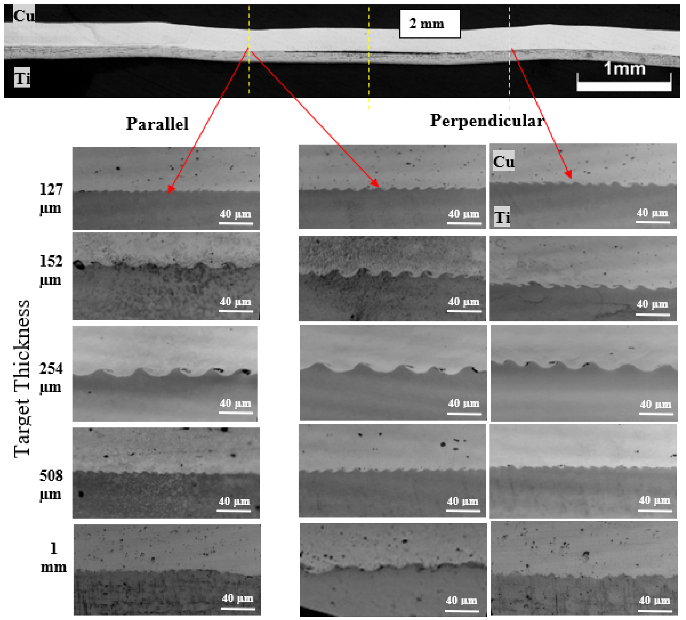
Figure 5 shows that interfacial waves provided greater magnitudes of wavelength and wave amplitude in the direction perpendicular to the stand-off in comparison to the parallel orientation. This phenomenon can be rationalized by the wave confinement resulting from the interaction between the stand-off and the jetting post-collision in the perpendicular scenario. Moreover, material dynamics experienced restrictions due to the presence of the stand-off. In contrast, in the parallel direction, the waves propagated uninhibitedly without encountering any constraining influences [23]. The interfacial wavelengths and amplitudes (the mean of the three largest wavelengths), at varying target thicknesses, were presented in the respective perpendicular and parallel directions and detailed in Table 2. The graphical representation in Figure 6 corroborated that the interfacial wave exhibited greater magnitudes in the perpendicular direction across all recorded target thicknesses. Moreover, the amplitude of these waves exhibited an escalating trend with increasing target thickness, up to a threshold of 254 µm, corresponding to twice the value of the flyer thickness. This interesting observation will be expounded upon in the subsequent section.
3.3. The Effect of Target Thickness
This section aimed to systematically explore and analyze how different target thicknesses affected the interfacial wavelength and amplitude during laser impact welding. Comparing the microstructures for both backing materials in Figure 7 and Figure 8, the trend observed is that the interfacial waves increased with increasing target thickness until it was twice that of the flyer thickness. Similar observations were previously discussed by Taeseon Lee, Jaramillo, and Zhang, Sh. [24,25,26]. Following the collision, the propagated waves traversed the entirety of the target’s thickness, subsequently undergoing reflection upon encountering its opposing surface which led to a more prolonged and intensified shockwave. Consequently, these waves became subject to the complicated interplay of constructive and destructive interference phenomena, influencing both their wavelengths and amplitude characteristics. An increase in the target’s thickness influenced both the amplitude and period of the waves. Additionally, the increase in target thickness was found to increase plastic deformation at the interface. This can be explained by the thicker materials possessing a higher mass, enabling them to absorb more energy when exposed to a laser beam. This heightened energy absorption leads to elevated temperatures and more substantial plastic deformation at the welding interface due to the higher resistance of thicker targets to bulk deformation. Moreover, the increased mass of thicker materials requires a longer time for laser energy to penetrate and reach the interface, allowing for greater heat accumulation and prolonged interaction time that further enhances plastic deformation. Variances in thermal conductivity between thicker and thinner materials can also impact heat distribution and dissipation, influencing plastic deformation behavior at the welding interface. Finally, the thicker material induces higher pressures at the interface during the welding process, promoting enhanced material flow and plastic deformation, thereby contributing to the development of a robust weld [27]. In summary, this trend was a result of the complex interplay between energy transfer, material behavior, and shockwave dynamics [8,25].
After exceeding double the thickness of the flyer, the target’s increased thickness was associated with a subsequent decrease in both wavelengths and amplitudes. This observation aligns with simulation studies by Taeseon Lee [24]. This phenomenon can be rationalized by the excessive dissipation of energy across the large thickness of the target, resulting from the propagation of waves over prolonged distances within the cross-sectional domain. Consequently, this mechanism provided a reduction in the plastic deformation flow along the interface connecting the flyer and target materials. The combination of these factors, including greater energy absorption and altered thermal dynamics, results in a diminished manifestation of interfacial waves when the target thickness exceeds twice that of the flyer. The corresponding interfacial wavelengths and amplitudes for different target thicknesses were quantified and depicted graphically, as shown in Table 3 and Figure 9.
In the case of steel backing at a target thickness of 1 mm, there was a deviation from the typical wavelength trend. Unlike the common pattern where the wavelength decreased after the target thickness surpassed twice the flyer thickness, in this case, it showed an increase instead. This behavior requires further accurate investigation to elucidate the triggering mechanisms.
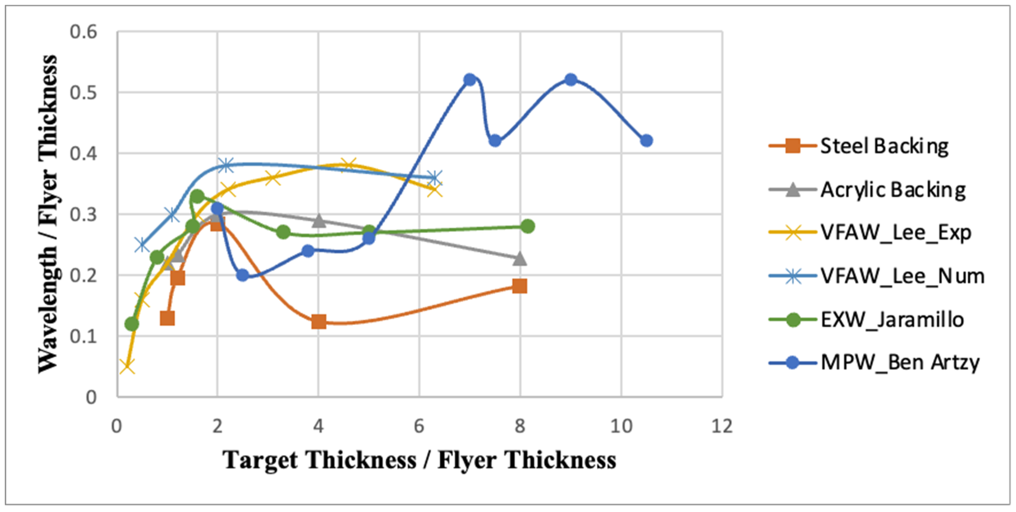
Figure 10 represented significant findings concerning the ratio of the wavelengths and the target to the flyer thickness, considering both backing materials. These results were analyzed in correlation with the established literature and the discussions presented by earlier researchers and showed consistency with their findings [11,13,25]
3.4. The Effect of Backing Material (Steel versus Acrylic Backing)
The impact of the backing material had a substantial influence over both the interfacial wave dynamics and the structural integrity of the joint, as illustrated before [16,28]. The shock impedance of a material has a great influence on impact welding, and it is dependent on its mechanical properties, specifically its density and elastic modulus. Steel is a dense and rigid material with a high elastic modulus, making it effective at absorbing and transmitting shockwaves. Acrylic, on the other hand, is a lighter and less rigid material, which generally results in lower shock impedance. Firstly, in the case of acrylic backing, the emergence and propagation of interfacial waves occurred at 1.5 mm from the central axis of the weld. In contrast, the interfacial waves elicited by steel backing became discernible at 2 mm from the central axis. This can be observed as shown in Figure 5 and Figure 8.
The interfacial wavelength and amplitude had greater magnitudes with acrylic backing compared to steel backing, as shown in Figure 11. This contrast in behavior can be attributed to the disparities in the wave reflection mechanisms between the two materials, as illustrated through the simulation obtained previously [29]. The acrylic backing had considerable wave reflection due to its inherent free-surface attributes. On the other hand, the steel backing had a density similar to the target material and thus had less wave reflection. This phenomenon is related to the acoustic impedance of materials and how it affects the reflection of waves. Acoustic impedance is a measure of how much a material resists the flow of sound energy and depending on the density and the speed of sound on the material [30]. When a wave encounters a boundary between two different materials, some of the wave energy is transmitted into the second material, and some is reflected back into the first material. The amount of reflection and transmission depends on the difference in acoustic impedance between the two materials. While the shockwave encounters a material with higher acoustic impedance (steel), there is an impedance mismatch, and the reflected wave tends to be compressive in nature. This is because the higher impedance material resists the compression of the wave, leading to a reflected wave with a compressive characteristic. Conversely, if the shockwave encounters a material with lower acoustic impedance (Acrylic), there is an impedance mismatch, and the reflected wave tends to be tensile in nature. This is because the lower impedance material allows for easier compression, leading to a reflected wave with a tensile nature [31].
Furthermore, steel had higher dissipation and absorption of energy compared to acrylic. This is due to steel’s denser and more metallic nature, allowing it to absorb and dissipate energy effectively. In contrast, acrylic, being a lighter and less dense material, tends to absorb less energy. The distinct molecular structures and compositions of steel and acrylic contribute to their contrasting abilities to absorb and handle energy. This dissimilarity results in the attenuation of wave intensity within the steel-backed configuration. A graphic representation of the correlation between wavelength and amplitude across diverse target thicknesses is shown in Figure 9, supporting the above-mentioned hypothesis.
It is noteworthy that the dimensions of the non-welded zone localized at the center of the weld, which had a great impact on the weld’s quality, were smaller for the acrylic backing compared to the steel, as shown in Figure 12. This noticeable distinction can be attributed to the divergent mechanical properties inherent in the respective backing materials [32]. Notably, steel, characterized by its elevated strength and hardness attributes, substantially influenced the distribution of forces and stress along the interface. This, in turn, rendered the initiation of cracks during the collision phase, consequently impeding the immediate bonding of interfacing materials [33]. Additionally, the ductility of steel, as compared to the brittleness of acrylic, introduces a great effect in influencing the angle of collision, which had a significant impact on the interfacial waves.
A further combination of this complex interaction is the higher energy dissipation observed in cases involving steel backing. This excessive dissipation negatively affects the reinforcement mechanisms operative at the interface, as it affected both frictional interactions and surface bonding efficacy [34]. The dimensions of the un-welded zone and graphical curves relative to the different target thickness for both backing materials, steel and acrylic, are shown in Table 4 and Figure 13.
3.5. Mechanical Testing (Lap Shear Test)
The outcomes of the lap shear tests conducted on the samples incorporating both types of backing materials are shown in Figure 14. Failures were observed on the copper (Cu) side within the welding nugget boundaries for target thicknesses of 127, 152, and 254 µm. In contrast, for thicknesses of 508 µm and 1 mm, the nugget was pulled out on the titanium (Ti) side, which provided an indication of the high strength of the welded joints, as discussed before [10,11,12,13,14].
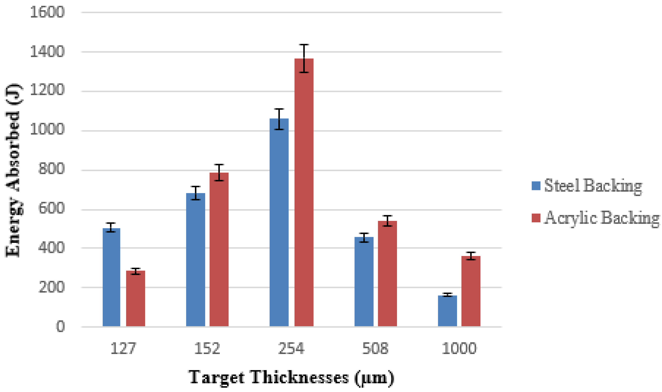
Furthermore, the load–displacement curves shown in Figure 15 offered insight into the mechanical behavior of the joints compared to the backings used. According to the observation on curves, the specimen featuring a target thickness of 254 µm, equivalent to twice the magnitude of the flyer’s thickness, stands out as exhibiting optimal performance. Moreover, Figure 16 and Figure 17 show the peak loads and energy absorption during the lap shear test across various target thicknesses for both steel and acrylic backing. While Figure 17 indicated that the maximum peak load occurred at 508 mm, Figure 17 demonstrates that the energy absorbed reached higher values at 254 mm. This is consistent with earlier descriptions which illustrated that the largest magnitudes of interfacial waves were obtained at this target thickness.
Additionally, a noticeable trend emerged when examining the load–displacement curves: those associated with the acrylic backing consistently exhibited elevated profiles and superior outcomes. These findings matched the discussions in the previous section which elucidated that acrylic backing provided better joints than steel backing.
4. Conclusions
An experimental investigation was conducted using augmented laser impact welding to examine how the thickness of the target and the backing materials affect the collision weld interface of a Ti-Cu joint. The results illustrated that:
- One noteworthy finding is that utilizing a single launch system, as described previously, enables the welding of efficient joints ranging from 127 µm to 1000 µm of target thickness, without the need for any alterations in the process.
- The wavelength and amplitude of the interfacial waves had greater magnitudes in the direction perpendicular to the stand-off, as compared to the parallel orientation.
- Increasing the target thickness increased the interfacial wave amplitude until approximately twice the flyer thickness was attained; beyond this threshold, a subsequent reduction in interfacial waves was observed.
- Interfacial waves formed closer to the weld center at a distance of 1.5 mm when an acrylic backing was employed, whereas this distance extended to 2 mm in the case of a steel backing.
- The unwelded zone at the center of the weld exhibited a smaller extent in instances where an acrylic backing was used, in contrast to scenarios involving a steel backing.
- Interfacial wavelength and amplitude were greater when an acrylic backing was used, as opposed to the use of a steel backing.
- During lap shear testing, in all cases, the welds did not experience failure at the interface; instead, failures occurred within the base metal. Failures occurred at the Cu side (for 127, 152, and 254 µm target thickness) leaving a complete weld nugget. For thicker target thickness (508 µm and 1 mm), failure occurred at the Ti side around the nugget which indicated that the interfacial joint had a high strength.
In all instances except for the thinnest target, the lap shear test results exhibited higher strengths for specimens with acrylic backing in comparison to those with steel backing.
Author Contributions
Conceptualization, M.A., A.V. and G.D.; methodology, M.A. and B.T.; software, B.T.; validation, A.V., B.P. and G.D.; investigation, M.A. and A.V.; writing—original draft preparation, M.A.; writing—review and editing, M.A., B.P. and G.D.; visualization, M.A., A.V. and B.P.; supervision, G.D. All authors have read and agreed to the published version of the manuscript.
Funding
This research is a part of a Ph.D. scholarship from the Egyptian government for the author M.A. (Mohammed Abdelmaola) at the OSU.
Data Availability Statement
The original contributions presented in the study are included in the article, further inquiries can be directed to the corresponding author.
Acknowledgments
The authors appreciate this PhD scholarship opportunity at OSU, provided by the Egyptian government for the author (Mohammed Abdelmaola). Additionally, the authors acknowledge partial support from the National Science Foundation Engineering Research Center for Hybrid Autonomous Manufacturing Moving from Evolution to Revolution (HAMMER-ERC) under Award Number EEC-2133630.
Conflicts of Interest
The authors declare no conflicts of interest.
References
- Khanna, O.P. Welding Technology; Dhanpat Rai & Co.: New Delhi, India, 2010. [Google Scholar]
- Messler, R.W. Joining of Materials and Structures: From Pragmatic Process to Enabling Technology; Elsevier: Amsterdam, The Netherlands; Boston, MA, USA, 2004. [Google Scholar]
- Martinsen, K.; Hu, S.J.; Carlson, B.E. Joining of dissimilar materials. CIRP Ann. 2015, 64, 679–699. [Google Scholar] [CrossRef]
- Wang, H.; Wang, K.; Zheng, W. Microstructure complexities of laser impact welded Al-Ti bonding interface. Scr. Mater. 2022, 211, 114488. [Google Scholar] [CrossRef]
- Dimatteo, V.; Ascari, A.; Liverani, E.; Fortunato, A. Experimental investigation on the effect of spot diameter on continuous-wave laser welding of copper and aluminum thin sheets for battery manufacturing. Opt. Laser Technol. 2022, 145, 107495. [Google Scholar] [CrossRef]
- Hunt, J.N. Wave formation in explosive welding. Philos. Mag. J. Theor. Exp. Appl. Phys. 1968, 17, 669–680. [Google Scholar] [CrossRef]
- Blazynski, T.Z. (Ed.) Explosive Welding, Forming and Compaction; Springer: Dordrecht, The Netherlands, 1983. [Google Scholar] [CrossRef]
- Godunov, S.K.; Deribas, A.A.; Zabrodin, A.V.; Kozin, N.S. Hydrodynamic effects in colliding solids. J. Comput. Phys. 1970, 5, 517–539. [Google Scholar] [CrossRef]
- Cowan, G.R.; Bergmann, O.R.; Holtzman, A.H. Mechanism of bond zone wave formation in explosion-clad metals. Metall. Trans. 1971, 2, 3145–3155. [Google Scholar] [CrossRef]
- Wang, K.; Wang, H.; Zhou, H.; Zheng, W.; Xu, A. Research Status and Prospect of Laser Impact Welding. Metals 2020, 10, 1444. [Google Scholar] [CrossRef]
- Lee, T.; Zhang, S.; Vivek, A.; Kinsey, B.; Daehn, G. Flyer Thickness Effect in the Impact Welding of Aluminum to Steel. J. Manuf. Sci. Eng. 2018, 140, 121002. [Google Scholar] [CrossRef]
- Wang, X.; Wang, X.; Li, F.; Lu, J.; Liu, H. Interface Kinematics of Laser Impact Welding of Ni and SS304 Based on Jet Indentation Mechanism. Metall. Mater. Trans. A 2020, 51, 2893–2904. [Google Scholar] [CrossRef]
- Ben-Artzy, A.; Stern, A.; Frage, N.; Shribman, V.; Sadot, O. Wave formation mechanism in magnetic pulse welding. Int. J. Impact Eng. 2010, 37, 397–404. [Google Scholar] [CrossRef]
- Vivek, A.; Liu, B.C.; Hansen, S.R.; Daehn, G.S. Accessing collision welding process window for titanium/copper welds with vaporizing foil actuators and grooved targets. J. Mater. Process. Technol. 2014, 214, 1583–1589. [Google Scholar] [CrossRef]
- Sunny, S.; Gleason, G.; Mathews, R.; Malik, A. Simulation of laser impact welding for dissimilar additively manufactured foils considering influence of inhomogeneous microstructure. Mater. Des. 2021, 198, 109372. [Google Scholar] [CrossRef]
- Kapil, A.; Lee, T.; Vivek, A.; Cooper, R.; Hetrick, E.; Daehn, G. Spot impact welding of an age-hardening aluminum alloy: Process, structure and properties. J. Manuf. Process. 2019, 37, 42–52. [Google Scholar] [CrossRef]
- Thurston, B.; Lewis, T.; Li, J.; Vivek, A.; Daehn, G. Augmented Laser Impact Welding: A New Process Demonstration in Welding Aluminum Alloy 2024-T3. J. Mater. Eng. Perform. 2023. [Google Scholar] [CrossRef]
- Wang, H.; Taber, G.; Liu, D.; Hansen, S.; Chowdhury, E.; Terry, S.; Lippold, J.; Daehn, G. Laser impact welding: Design of apparatus and parametric optimization. J. Manuf. Process. 2015, 19, 118–124. [Google Scholar] [CrossRef]
- Wang, Q.; Wang, H.; Ran, M.; Tong, Z.; Wang, R.; Zheng, W. The achievement of lap weld and gap control for laser impact welding with water as the confinement layer. J. Manuf. Process. 2023, 95, 105–114. [Google Scholar] [CrossRef]
- Rija Nirina, R.; Sapanathan, T.; Buiron, N.; Rachik, M. Magnetic pulse welding of Al/Al and Al/Cu metal pairs: Consequences of the dissimilar combination on the interfacial behavior during the welding process. J. Manuf. Process. 2015, 20, 112–127. [Google Scholar] [CrossRef]
- Jaramillo, D.; Szecket, A.; Inal, O.T. On the transition from a waveless to a wavy interface in explosive welding. Mater. Sci. Eng. 1987, 91, 217–222. [Google Scholar] [CrossRef]
- Kawano, R.; Tanaka, S.; Inao, D.; Hokamoto, K. Acceleration of metal plates by hybridization of electrical and chemical energy for potential application in high-velocity impact welding. J. Mater. Process. Technol. 2023, 318, 118014. [Google Scholar] [CrossRef]
- Wang, Q.; Wang, K.; Wang, H.; Zheng, W. Variety of microstructure and mechanical properties along the laser impact welded interface. Sci. Technol. Weld. Join. 2023, 28, 128–136. [Google Scholar] [CrossRef]
- Lee, T.; Zhang, S.; Vivek, A.; Daehn, G.; Kinsey, B. Wave formation in impact welding: Study of the Cu–Ti system. CIRP Ann. 2019, 68, 261–264. [Google Scholar] [CrossRef]
- Jaramillov, D.; Inal, O.T.; Szecket, A. Effect of base plate thickness on wave size and wave morphology in explosively welded couples. J. Mater. Sci. 1987, 22, 3143–3147. [Google Scholar] [CrossRef]
- Zhang, S.; Lueg-Althoff, J.; Hahn, M.; Tekkaya, A.E.; Kinsey, B. Effect of Process Parameters on Wavy Interfacial Morphology During Magnetic Pulse Welding. J. Manuf. Sci. Eng. 2020, 143, 011010. [Google Scholar] [CrossRef]
- Gleason, G.; Sunny, S.; Mathews, R.; Malik, A. Numerical investigation of the transient interfacial material behavior during laser impact welding. Scr. Mater. 2022, 208, 114325. [Google Scholar] [CrossRef]
- Moghaddas, M.A.; Abdollah-zadeh, A.; Hajian, M. The effects of back-plate support and welded metal type on the characteristics of joints produced by magnetic pulse welding. Int. J. Adv. Manuf. Technol. 2019, 102, 379–392. [Google Scholar] [CrossRef]
- Meng, Z.; Zhou, R.; Gong, M.; Guo, W.; Liu, W.; Huang, S. Interface formation and interlayer factors of three-dissimilar-metal layers joint in impact welding. J. Manuf. Process. 2021, 70, 414–426. [Google Scholar] [CrossRef]
- Meyers, M.A. Dynamic Behavior of Materials, 1st ed.; John Wiley & Sons, Ltd.: Hoboken, NJ, USA, 1994. [Google Scholar] [CrossRef]
- Gleason, G.; Bailey, K.; Sunny, S.; Malik, A.; Bernal, R.A. Influence of surface roughness on the transient interfacial phenomena in laser impact welding. J. Manuf. Process. 2022, 80, 480–490. [Google Scholar] [CrossRef]
- Liu, H.; Jin, H.; Shao, M.; Tang, H.; Wang, X. Investigation on Interface Morphology and Mechanical Properties of Three-Layer Laser Impact Welding of Cu/Al/Cu. Metall. Mater. Trans. A 2019, 50, 1273–1282. [Google Scholar] [CrossRef]
- Gupta, M.K.; Singh, N.K.; Gupta, N.K. Energy dissipation and notch sensitivity of mild steel at different strain rates and temperatures. Int. J. Impact Eng. 2023, 178, 104610. [Google Scholar] [CrossRef]
- Liu, H.; Yang, B.; Wang, C.; Han, Y.; Liu, D. The mechanisms and applications of friction energy dissipation. Friction 2022, 11. [Google Scholar] [CrossRef]
Figure 1.
Laser system and experimental chamber.
Figure 2.
Schematic of the directionality of the joint interface.
Figure 3.
The flyer velocity as a function of displacement.
Figure 4.
Various frames (a–l) captured every 2 µs by a high-speed camera following laser irradiation reveal the protrusion and the formation of cone-shaped dimples on the titanium flyer plate.
Figure 4.
Various frames (a–l) captured every 2 µs by a high-speed camera following laser irradiation reveal the protrusion and the formation of cone-shaped dimples on the titanium flyer plate.

Figure 5.
Microstructures of interfacial waves at different target thicknesses in both perpendicular and parallel directions, with steel backing.
Figure 5.
Microstructures of interfacial waves at different target thicknesses in both perpendicular and parallel directions, with steel backing.

Figure 6.
Interfacial wavelength and amplitude, for different target thicknesses, in both perpendicular and parallel directions, with steel backing.
Figure 6.
Interfacial wavelength and amplitude, for different target thicknesses, in both perpendicular and parallel directions, with steel backing.
Figure 7.
The effect of different target thicknesses on the interfacial waves with steel backing in a direction perpendicular to the stand-off.
Figure 7.
The effect of different target thicknesses on the interfacial waves with steel backing in a direction perpendicular to the stand-off.

Figure 8.
Effect of different target thicknesses on the interfacial waves, with acrylic backing.
Figure 9.
Interfacial wavelength and amplitude for different target thicknesses with steel backing and acrylic backing.
Figure 9.
Interfacial wavelength and amplitude for different target thicknesses with steel backing and acrylic backing.
Figure 10.
The impact of normalized target thickness on the wavelength relative to the literature.

Figure 11.
Interfacial waves for different target thicknesses for both steel and acrylic backing at the left side from the center of the weld.
Figure 11.
Interfacial waves for different target thicknesses for both steel and acrylic backing at the left side from the center of the weld.
Figure 12.
The dimensions of the non-welded zone localized at the center of the weld with steel and acrylic backing.
Figure 12.
The dimensions of the non-welded zone localized at the center of the weld with steel and acrylic backing.

Figure 13.
The un-welded zone relative to the different target thicknesses with steel and acrylic backing.
Figure 13.
The un-welded zone relative to the different target thicknesses with steel and acrylic backing.

Figure 14.
Lap shear-tested samples with (a) steel (b) acrylic backing.

Figure 15.
Load–displacement curves for lap shear test of welded samples with (a) steel (b) acrylic backing.
Figure 15.
Load–displacement curves for lap shear test of welded samples with (a) steel (b) acrylic backing.
Figure 16.
Peak loads during lap shear test at different target thicknesses for steel and acrylic backing.
Figure 16.
Peak loads during lap shear test at different target thicknesses for steel and acrylic backing.
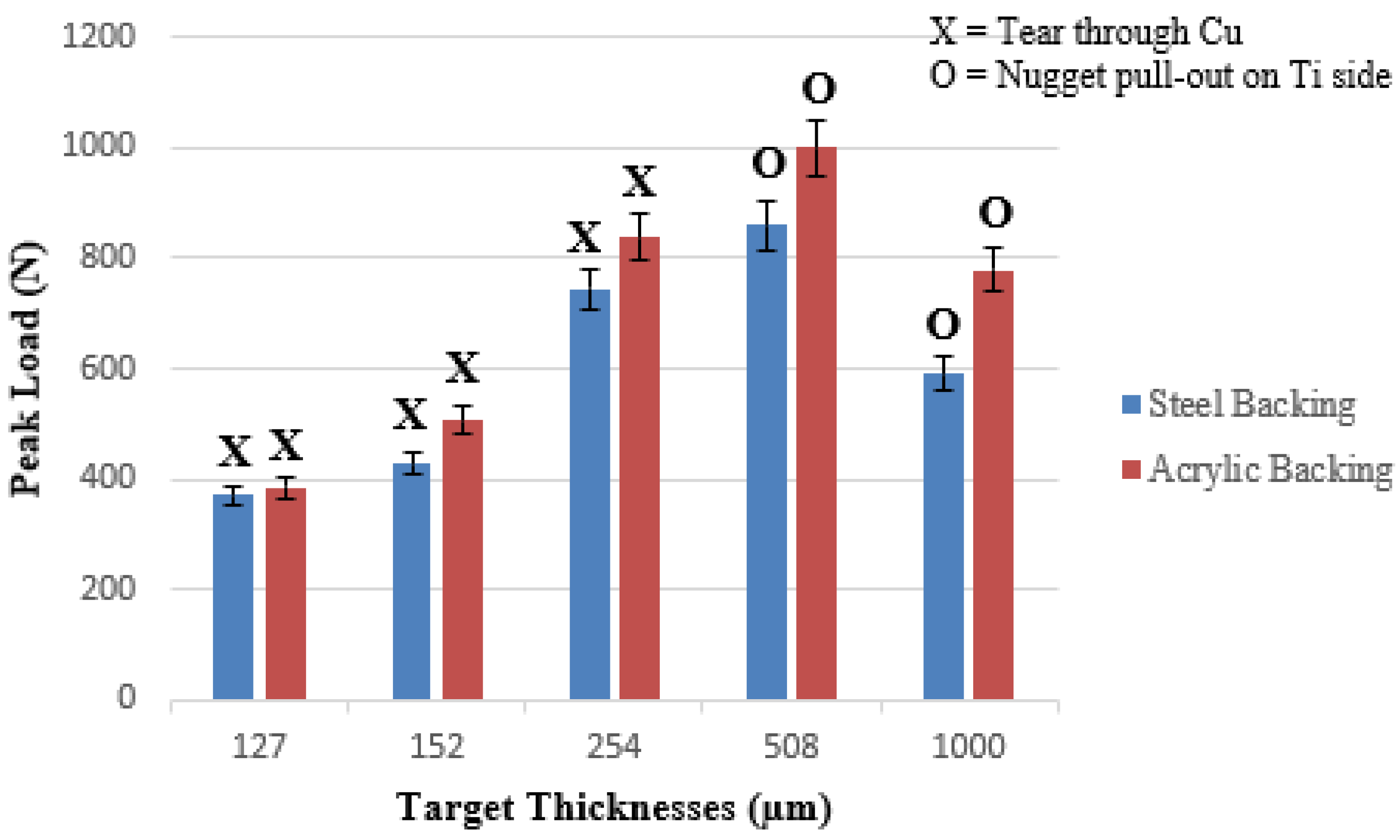
Figure 17.
Energy absorbed during lap shear test at different target thicknesses for steel and acrylic backing.
Figure 17.
Energy absorbed during lap shear test at different target thicknesses for steel and acrylic backing.

Table 1.
Select laser parameters.
| Power Density (GW/cm2) | Energy (J) | Wavelength (nm) | Pulse Width (nm) | Spot Size (mm) |
|---|---|---|---|---|
| 1.34 | 3.14 | 1064 | 8 | 5.22 |
Table 2.
The values of interfacial wavelength and amplitude, for different target thicknesses, in both perpendicular and parallel directions, with steel backing.
Table 2.
The values of interfacial wavelength and amplitude, for different target thicknesses, in both perpendicular and parallel directions, with steel backing.
| Directionality | Perpendicular | Parallel | |||
|---|---|---|---|---|---|
| Target Thickness (µm) | Wavelength (µm) | Amplitude (µm) | Wavelength (µm) | Amplitude (µm) | |
| 127 | 16.46 | 3.11 | 9.35 | 1.46 | |
| 152 | 25 | 4.6 | 22.8 | 4.3 | |
| 254 | 36.23 | 8.42 | 35.4 | 7.76 | |
| 508 | 15.8 | 2.83 | 9.85 | 1.85 | |
| 1000 | 23.15 | 3.1 | 20.45 | 2.26 | |
Table 3.
The values of interfacial wavelengths and amplitudes for different target thicknesses with steel and acrylic backing.
Table 3.
The values of interfacial wavelengths and amplitudes for different target thicknesses with steel and acrylic backing.
| Target Thickness (µm) | Steel Backing | Acrylic Backing | ||
|---|---|---|---|---|
| Wavelength (µm) | Amplitude (µm) | Wavelength (µm) | Amplitude (µm) | |
| 127 | 16.46 | 3.11 | 28 | 4.7 |
| 152 | 25 | 4.6 | 29.6 | 5.53 |
| 254 | 36.23 | 8.42 | 38.5 | 9.06 |
| 508 | 15.8 | 2.83 | 38 | 4.43 |
| 1000 | 23.15 | 3.1 | 29.04 | 5.5 |
Table 4.
Width of the un-welded zone at the center of the weld.
| Target Thickness (mm) | Steel Backing (mm) | Acrylic Backing (mm) |
|---|---|---|
| 0.127 | 2.14 | 0.33 |
| 0.152 | 1.95 | 0.31 |
| 0.254 | 1.91 | 0.27 |
| 0.508 | 2.16 | 0.29 |
| 1 | 2.2 | 1.65 |
Disclaimer/Publisher’s Note: The statements, opinions and data contained in all publications are solely those of the individual author(s) and contributor(s) and not of MDPI and/or the editor(s). MDPI and/or the editor(s) disclaim responsibility for any injury to people or property resulting from any ideas, methods, instructions or products referred to in the content. |
© 2024 by the authors. Licensee MDPI, Basel, Switzerland. This article is an open access article distributed under the terms and conditions of the Creative Commons Attribution (CC BY) license (https://creativecommons.org/licenses/by/4.0/).
Share and Cite
MDPI and ACS Style
Abdelmaola, M.; Thurston, B.; Panton, B.; Vivek, A.; Daehn, G. The Effects of Target Thicknesses and Backing Materials on a Ti-Cu Collision Weld Interface Using Laser Impact Welding. Metals 2024, 14, 342. https://doi.org/10.3390/met14030342
AMA Style
Abdelmaola M, Thurston B, Panton B, Vivek A, Daehn G. The Effects of Target Thicknesses and Backing Materials on a Ti-Cu Collision Weld Interface Using Laser Impact Welding. Metals. 2024; 14(3):342. https://doi.org/10.3390/met14030342
Chicago/Turabian StyleAbdelmaola, Mohammed, Brian Thurston, Boyd Panton, Anupam Vivek, and Glenn Daehn. 2024. "The Effects of Target Thicknesses and Backing Materials on a Ti-Cu Collision Weld Interface Using Laser Impact Welding" Metals 14, no. 3: 342. https://doi.org/10.3390/met14030342
Note that from the first issue of 2016, this journal uses article numbers instead of page numbers. See further details here.