
Effect of Hydrogen on Fatigue Life and Fracture Morphologies of TRIP-Aided Martensitic Steels with Added Nitrogen


1
Department of Mechanical Engineering and Intelligent Systems, Faculty of Engineering, Tohoku Gakuin University, Sendai 984-8588, Japan
2
Department of Engineering, Course of Mechanics and Robotics, National Institute of Technology (KOSEN), Nagano College, Nagano 381-8550, Japan
3
Department of Mechanical System Engineering, College of Engineering, Ibaraki University, Hitachi 316-8511, Japan
4
Japan Atomic Energy Agency, Tokai 319-1195, Japan
5
Institute for Materials Research, Tohoku University, Sendai 980-8577, Japan
*
Author to whom correspondence should be addressed.
Metals 2024, 14(3), 346; https://doi.org/10.3390/met14030346
Submission received: 9 February 2024
/
Revised: 9 March 2024
/
Accepted: 14 March 2024
/
Published: 17 March 2024
(This article belongs to the Special Issue Fatigue, Creep Behavior and Fracture Mechanics of Metals)
Abstract
:The effects of hydrogen on the tensile properties, fatigue life, and tensile and fatigue fracture morphologies of nitrogen-added ultrahigh-strength transformation-induced plasticity (TRIP)-aided martensitic (TM) steels were investigated. The total elongation and number of cycles to failure (Nf) of the hydrogen-charged TM steels decreased with the addition of nitrogen; in particular, adding 100 ppm of nitrogen decreased the total elongation and Nf of the TM steels. The quasi-cleavage cracking around the AlN occurred near the sample surface, which is the crack propagation region, although dimples appeared at the center of the fracture surface in the tensile samples. The initial fatigue crack initiated at the AlN precipitate or matrix/AlN interface, located at the notch root. During crack propagation, new cracks were initiated at the AlN precipitates or matrix/AlN interfaces, while quasi-cleavage crack regions were observed around the AlN precipitates. The decrease in the total elongation and Nf of the hydrogen-charged TM steel with 100 ppm of added nitrogen might be attributable to the crack initiation around the AlN precipitates formed by a large amount of hydrogen trapped at the AlN precipitates and matrix/AlN interfaces, and to the dense distribution of AlN, which promoted crack linkage.
1. Introduction
High-strength transformation-induced plasticity (TRIP) [1]-aided steels with tensile strengths of 980 and 1180 MPa have been applied in automobile frame parts in recent decades to reduce vehicle weight and improve collision safety. The press formability and impact and fatigue properties are degraded when the tensile strength exceeds 980 MPa. In addition, hydrogen embrittlement [2] is a crucial consideration in the adoption of high-strength steels in automobiles. Hydrogen embrittlement is caused by hydrogen introduced during production processes and service use, such as pickling, plating, and corrosion, through contact with airborne sea salt and splashes containing antifreeze salts. Sugimoto et al. systematically investigated the tensile properties [3,4,5], press formabilities [6], fatigue properties [7], V-bendabilities [6], hydrogen embrittlement properties [4,5], and impact properties [8] of high-strength TRIP-aided steels with tensile strengths exceeding 1000 MPa. They found that excellent properties were obtained in these steels due to the effective TRIP effect of retained austenite. Because the addition of nitrogen to steel can increase its tensile strength through solution-hardening and fine nitride precipitation, and improve its corrosion resistance [9,10,11], it is expected that the tensile strength and corrosion resistance of high-strength TRIP-aided steels can also be further improved by nitrogen addition. Moreover, Kim et al. [12] and Luo et al. [13] investigated the effect of nitrogen on the hydrogen embrittlement of austenitic stainless steels, and reported that the hydrogen embrittlement properties of nitrogen-added austenitic stainless steels were improved owing to the decrease in the diffusivity of hydrogen and the improvement of the stability of austenite. Therefore, the hydrogen embrittlement properties of high-strength TRIP-aided steels are expected to be improved by nitrogen addition. However, the effect of nitrogen addition on the hydrogen embrittlement behavior of the TRIP-aided steels possessing metastable retained austenite is not revealed sufficiently. In addition, because the fatigue strength of metallic materials increases with their tensile strength [14], nitrogen addition could also improve the fatigue properties of high-strength TRIP-aided steels [7].
In recent years, many investigators have studied the fatigue properties [15,16,17] and fatigue fracture mechanisms of high-strength steels [15,18,19] used for carbon-neutral applications, such as fuel cell vehicles powered by hydrogen energy. Murakami et al. [19] investigated the fatigue properties of austenitic stainless steels and tempered martensitic steels in a high-pressure hydrogen gas atmosphere, and found that the hydrogen environment accelerated crack propagation, although the fatigue limit of these steels did not change significantly. Matsuoka et al. [18,20] investigated the crack propagation behavior of austenitic stainless steels. They proposed a mechanism for dislocation emission at the crack tip of the plastic deformation region under hydrogen-containing conditions and a crack propagation mechanism. Fernández-Sousa et al. [21] investigated the effect of hydrogen trapping on hydrogen diffusion and hydrogen embrittlement under repetitive loading conditions. They found that the hydrogen embrittlement fracture was suppressed by the highly dispersed hydrogen-trapping sites with high binding energies in the microstructure. Guo et al. [22] investigated the effects of retained austenite morphologies on the fatigue properties and the fatigue crack initiation and propagation behaviors in high-strength steels containing retained austenite. They reported that crack propagation was suppressed owing to the martensitic transformation of film-type retained austenite at the microcrack tip, and that intergranular fracture was promoted by crack initiation at the retained austenite and/or the martensite/retained austenite interfaces. Malitckii et al. [23] investigated the effects of retained austenite on hydrogen trapping and fatigue fracture in high-strength steel sheets. However, the effect of hydrogen on the fatigue properties and fatigue fracture behaviors of high-strength steel for automotive applications is still poorly understood.
In this study, the effects of hydrogen on the tensile properties, fatigue life, and fatigue fracture behavior of 1470 MPa-grade TRIP-aided martensitic (TM) steel with additive nitrogen were investigated for the potential applications of TM steel as a high-strength steel with a tensile strength of 1470 MPa in automotive structural parts.
2. Materials and Methods
Table 1 lists the chemical compositions of the steels used in this study. A cold-rolled steel sheet with a chemical composition of 0.2 C–1.0 Si–1.5 Mn–0.5 Al–0.05 Nb (mass%) was used as the base steel (steel A), and nitrogen was added at 100 and 200 mass ppm to the base steel while the same amount of carbon was removed (C + N = 0.2 mass%). The martensite-transformation-start temperature (MS) [24], which was calculated using Equation (1), is listed in Table 1.
MS (°C) = 550 – 361 × (%[C]) – 39 × (%[Mn]) – 0 × (%[Si]) + 30 × (%[Al]) – 5 × (%[Mo])
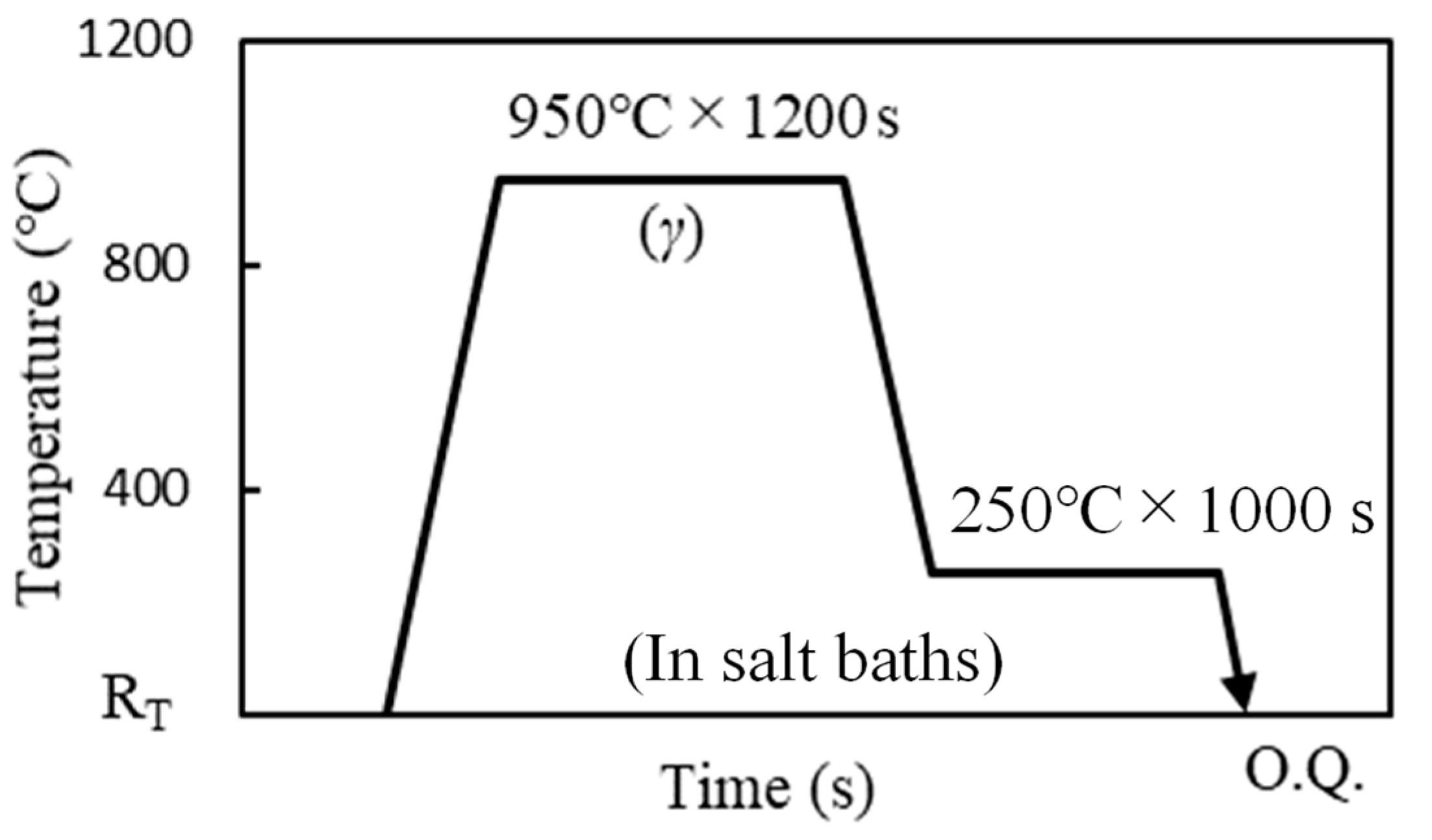
Figure 1 shows the heat treatment process of the steels. The TM steels were produced by annealing at 950 °C for 1200 s followed by isothermal transformation treatment at 250 °C for 1000 s in salt baths after the test specimens were prepared using laser cutting. Here, the TM steels produced from steels A, B, and C are referred to as TM-A, TM-B, and TM-C steels, respectively.
The volume fraction of retained austenite (fγ) was quantified using the integral intensities of the α-Fe200, α-Fe211, γ-Fe200, γ-Fe220, and γ-Fe311 diffraction peaks obtained using CuKα radiation. The carbon concentration in retained austenite (Cγ) was estimated using Equation (2) [25] from the average lattice parameter (aγ (×10−10 m)), which was measured from the γ-Fe200, γ-Fe220, and γ-Fe311 diffraction peaks of CuKα radiation.
where Mnγ, Alγ, Nγ, Nbγ, and Moγ represent the concentrations of the respective elements (mass%) in the retained austenite. In this study, the concentrations of the added alloying elements were substituted for these concentrations.
aγ = 3.5780 + 0.0330Cγ + 0.00095Mnγ + 0.0056Alγ + 0.0220Nγ + 0.0051Nbγ + 0.0031Moγ
Tensile tests were carried out on a tensile testing machine at a crosshead speed of 10 mm/min (initial strain rate of 8.33 × 10⁻³/s) at 25 °C in ambient atmospheres with and without hydrogen using tensile specimens with a gauge length of 15 mm, width of 6 mm, and thickness of 1.2 mm at the parallel part, as shown in Figure 2a [7]. The tensile tests were performed twice for each tensile testing condition. The tensile properties were evaluated based on the tensile strength (TS), yield or 0.2% offset proof stress (YS), total elongation (TEl), and uniform elongation (UEl). The hydrogen embrittlement properties were evaluated based on the hydrogen embrittlement susceptibility (HES), which was calculated as
where ε0 and ε1 denote the total elongation without and with hydrogen, respectively.
HES = (1 − (ε1/ε0))
Load-controlled fatigue tests were conducted on a servohydraulic fatigue testing machine. A sinusoidal waveform of 10 Hz was applied at a stress ratio of 0.1 and 25 °C on a fatigue specimen with a width of 5 mm, radius of 2.5 mm at the notch root, and thickness of 1.2 mm, as shown in Figure 2b [7]. The stress concentration factor at the notch tip was 1.6. The fatigue properties without hydrogen were evaluated based on the fatigue limit, which is defined as the stress amplitude (Δσ = (σmax − σmin)/2) at which no failure occurred until 1 × 10⁷ cycles. In the specimens with hydrogen, the fatigue life at the stress amplitude of Δσ = 135 MPa was used to evaluate the fatigue properties because the fatigue limit did not appear until the stress amplitude decreased to Δσ = 135 MPa.
Figure 3 shows the hydrogen charging and fatigue test apparatuses. Hydrogen charging was performed on the tensile and fatigue specimens via cathode charging. The specimen and a platinum wire were used as the cathode and anode, respectively. The surfaces and side surfaces of the parallel part of the tensile test specimen and those at the center, which contained a 14 mm-long notch region in the fatigue test specimen, were charged with hydrogen, and the other portions were masked using silicon sealant. Hydrogen pre-charging was conducted at a current density of 10 A/m2 at 25 °C for 48 h in a 3 wt. % NaCl solution containing 3 g/L NH4SCN before the tensile and fatigue tests [4]. In addition, hydrogen charging was conducted continuously during the fatigue tests under the same conditions as those applied for hydrogen pre-charging.
The hydrogen concentrations in the steels were measured using thermal desorption spectrometry (TDS). The samples, which were charged with hydrogen under the same hydrogen charging conditions as those of the tensile and fatigue samples, were heated from room temperature to 800 °C at a heating rate of 100 °C/h. The hydrogen desorbed during the TDS measurements was detected using a quadrupole mass spectrometer. The diffusible hydrogen concentration, which affects the occurrence of hydrogen embrittlement, was defined as the total amount of hydrogen desorbed from room temperature to 200 °C.
The microstructures of the heat-treated TM steels were observed using scanning electron microscopy (SEM) (Hitachi High-Tech Corporation and JEOL Ltd., Tokyo and Akishima, Japan), electron-backscatter diffraction pattern (EBSD) (Oxford Instruments, Abingdon-on-Thames, United Kingdom) equipped with SEM and transmission electron microscopy (TEM) (JEOL Ltd., Tokyo, Japan). The SEM and EBSD samples mounted in an acryl polymer were prepared by grinding using waterproof papers of #320, #600 and #1200 grids (Sankyo Rikagaku Co., Ltd., Okegawa, Japan), followed by polishing with 9 and 3 μm single-crystal diamond slurries and 0.06 μm colloidal silica for 5 min each. The SEM sample was etched using a 3% nital etchant. The samples with a diameter of 3 mm were used for TEM observation. The thickness of the sample was reduced to 0.1 mm using waterproof papers of #320, #600, #1200, #1500 and #2000 grids, and then the TEM sample was punched using a punch-die set with the diameter of 3 mm and a clearance of 10%. The punched sample was polished on a dimple grinder with 0.3 μm diamond paste and 0.06 μm colloidal silica until the thickness at the center of the TEM sample reached 0.03 μm. Finally, the TEM sample was electrochemically polished using a 4.2% perchloric acid + 21.2% glycerin + 74.5% ethanol solution at 26 V. The fracture surfaces of the tensile and fatigue specimens were observed using SEM.
3. Results and Discussion
3.1. Microstructure and Tensile Properties
Figure 4 shows the microstructures of the TM steels observed by SEM and TEM. The band contrast and phase maps analyzed by electron backscatter diffraction (EBSD) for aluminum nitride (AlN) precipitated in the TM steels are shown in Figure 5. In the phase maps, the light blue, blue, and red regions, respectively, correspond to AlN and martensite, which possessed body-centered cubic structures, and retained austenite, with a face-centered cubic structure. The microstructure of the TM steels consisted of a martensite matrix, fine retained austenite located at the martensite lath boundaries, and martensite–austenite constituents at the triple junctions of the prior austenite grain boundaries (Figure 4). Coarse AlN was precipitated in TM-B and TM-C steels containing 100 and 200 ppm nitrogen, respectively, whereas a fine and uniform martensite matrix was found in the TM steels. The size of the AlN precipitates increased with the nitrogen content from approximately 10 μm in length in the rolling direction in the TM-B steel to approximately 20 μm in length in the rolling direction in the TM-C steel (Figure 5).
Figure 6 shows the nominal stress–strain curves of the TM steels with and without hydrogen. The tensile properties and retained austenite characteristics of the TM steels without hydrogen are listed in Table 2 [7]. The TS, YS, TEl, and UEl values of the TM steels were 1369–1396 MPa, 1083–1111 MPa, 14.0–16.5%, and 6.6–6.9%, respectively. The addition of 100 ppm nitrogen did not change TS, YS, TEl, and UEl significantly, whereas the addition of 200 ppm nitrogen slightly decreased TS, YS, and TEl. The initial volume fraction of retained austenite (fγ0) in the TM steels was not significantly changed by the addition of 200 ppm nitrogen, whereas the initial carbon concentration in the retained austenite (Cγ0) increased. The fracture elongation of the hydrogen-charged TM steels decreased, although the yield and maximum strengths did not change significantly. Figure 7 shows a comparison of the TS and TEl of TM steels with and without hydrogen. The HES of the TM steels is shown in Figure 8. Hydrogen charging significantly decreased the TEl of the TM steels, although their TS did not change significantly. In particular, the TEl of hydrogen-charged TM-B and TM-C steels, which contained significant amounts of nitrogen, decreased compared to that of TM-A steel, which was a conventional TM steel. TM-B steel showed high HES, whereas TM-A and TM-C steels had similar HES values. The yielding and work-hardening behavior of the TM steels with and without hydrogen did not change, implying that the transformation behavior of retained austenite did not change owing to the hydrogen absorption. It has been reported that the TRIP-aided bainitic ferrite steels with and without hydrogen exhibited similar trends of the transformation of retained austenite due to the high stability of retained austenite, owing to the carbon concentration, the morphology of retained austenite and the matrix structure surrounding the retained austenite [5]. It is expected that the high stability of retained austenite was also achieved owing to the microstructural features in the TM steels.
3.2. Fatigue Properties
Figure 9 shows the S–N curves of the nitrogen-containing TM steels. The FL of the nitrogen-added TM steels without hydrogen and the number of cycles to failure (Nf) at the stress amplitude (Δσ) of 135 MPa of the TM steels with hydrogen are shown in Figure 10. In the TM steels without hydrogen charging, FL decreased from 270 to 252 MPa with increasing nitrogen content. TM-A steel, which contained 0 ppm nitrogen, exhibited the highest fatigue limit (Figure 9 and Figure 10). Meanwhile, Nf was reduced in the hydrogen-charged TM steels at the same Δσ as that in the tests on the steels without hydrogen. Moreover, FL did not appear in the TM steels with hydrogen, even when the Δσ was decreased to 135 MPa. Comparing the Nf at the Δσ of 135 MPa of the TM steels, the Nf of 5,062,939 of TM-B steel containing 100 ppm nitrogen was smaller than the Nf values of 6,512,960 and 6,079,119 of nitrogen-free TM-A and TM-C steel containing 200 ppm nitrogen, respectively, indicating that TM-B steel had a short fatigue life (Figure 10).
3.3. Fracture Surfaces
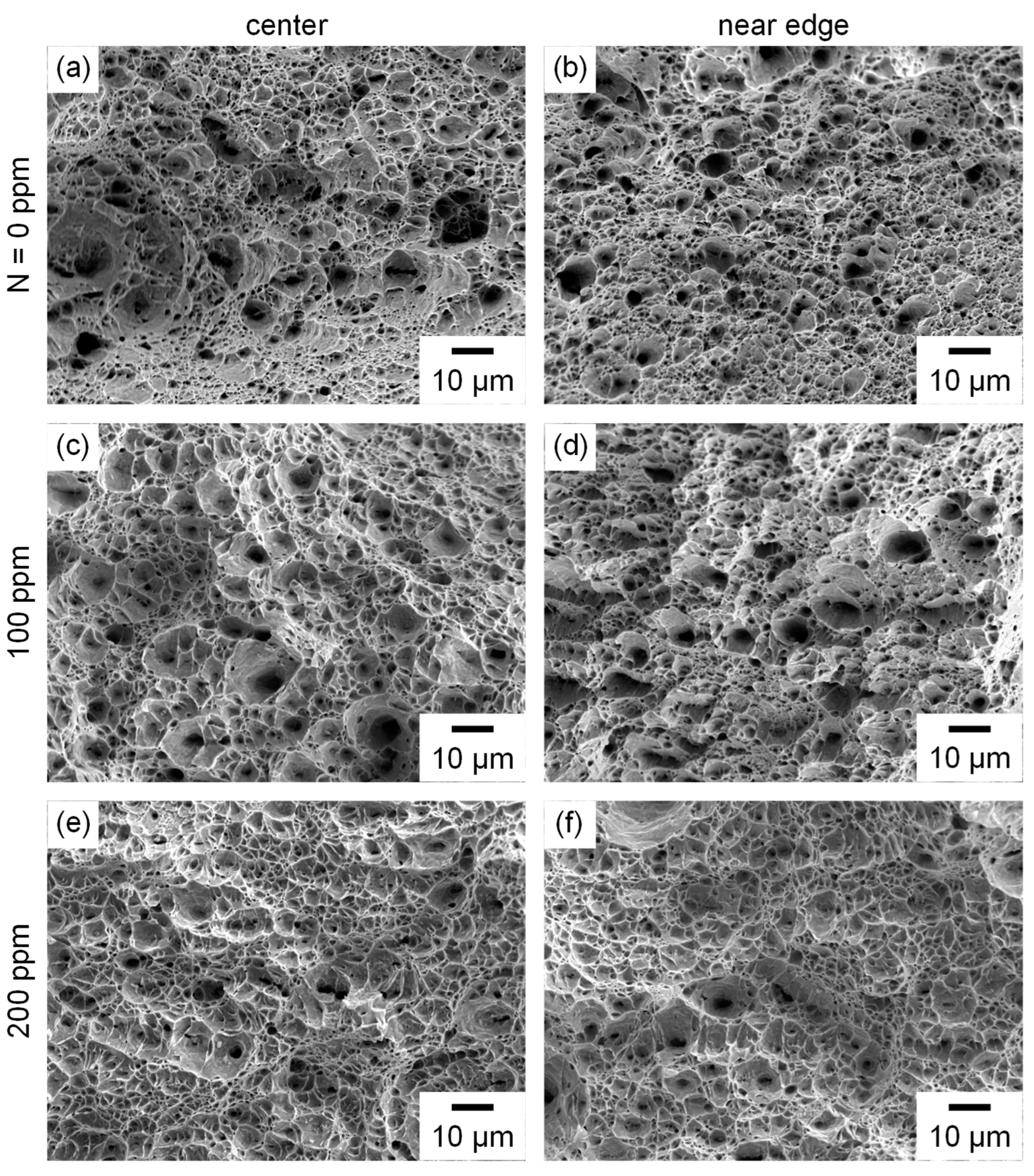
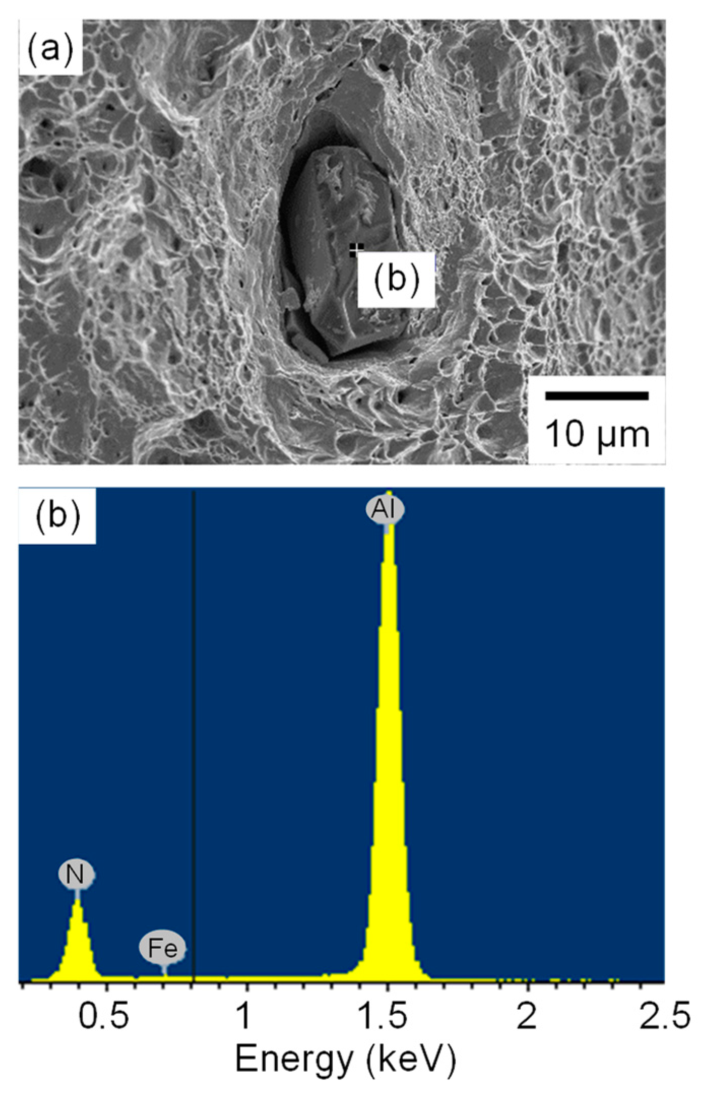
Figure 11 and Figure 12 show SEM images of the fracture surfaces of the TM steels after tensile tests conducted without and with hydrogen, respectively. For the tensile tests conducted without hydrogen, the fracture surface of each TM steel exhibited fine dimples at both the center and the edges. In contrast, though fine dimples appeared at the centers of the fracture surfaces in the hydrogen-charged TM steels, quasi-cleavage facets around the precipitates were observed at the edges of nitrogen-containing TM-B and TM-C steels. It is noted that the sizes and depths of dimples at the center of the fracture surface appeared to be similar in the TM steels without and with hydrogen charging. Figure 13 shows the results of energy-dispersive X-ray spectroscopy (EDX) analysis of the precipitates on the fracture surface of the TM-C steel without hydrogen charging. The EDX result confirms that the precipitates were AlN.
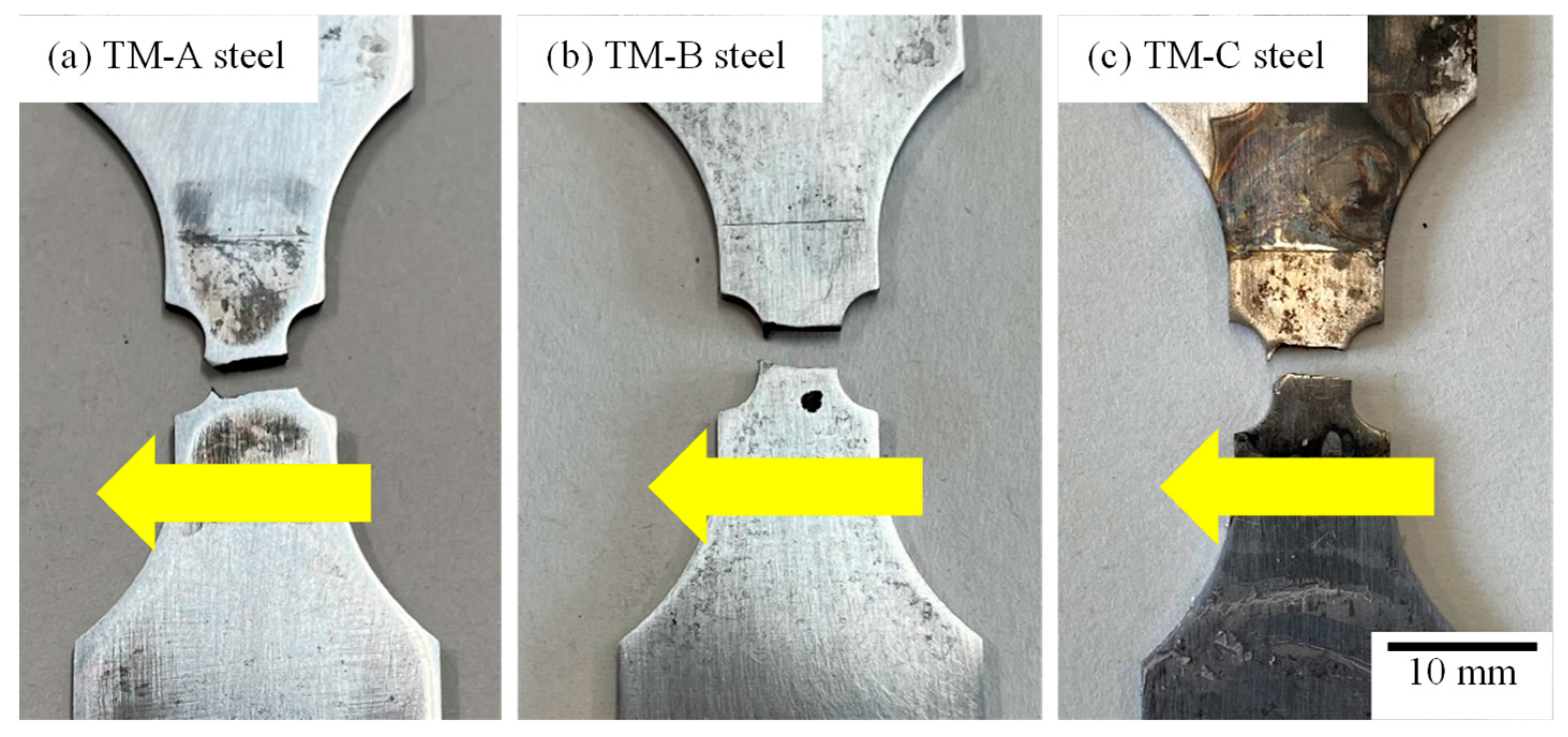
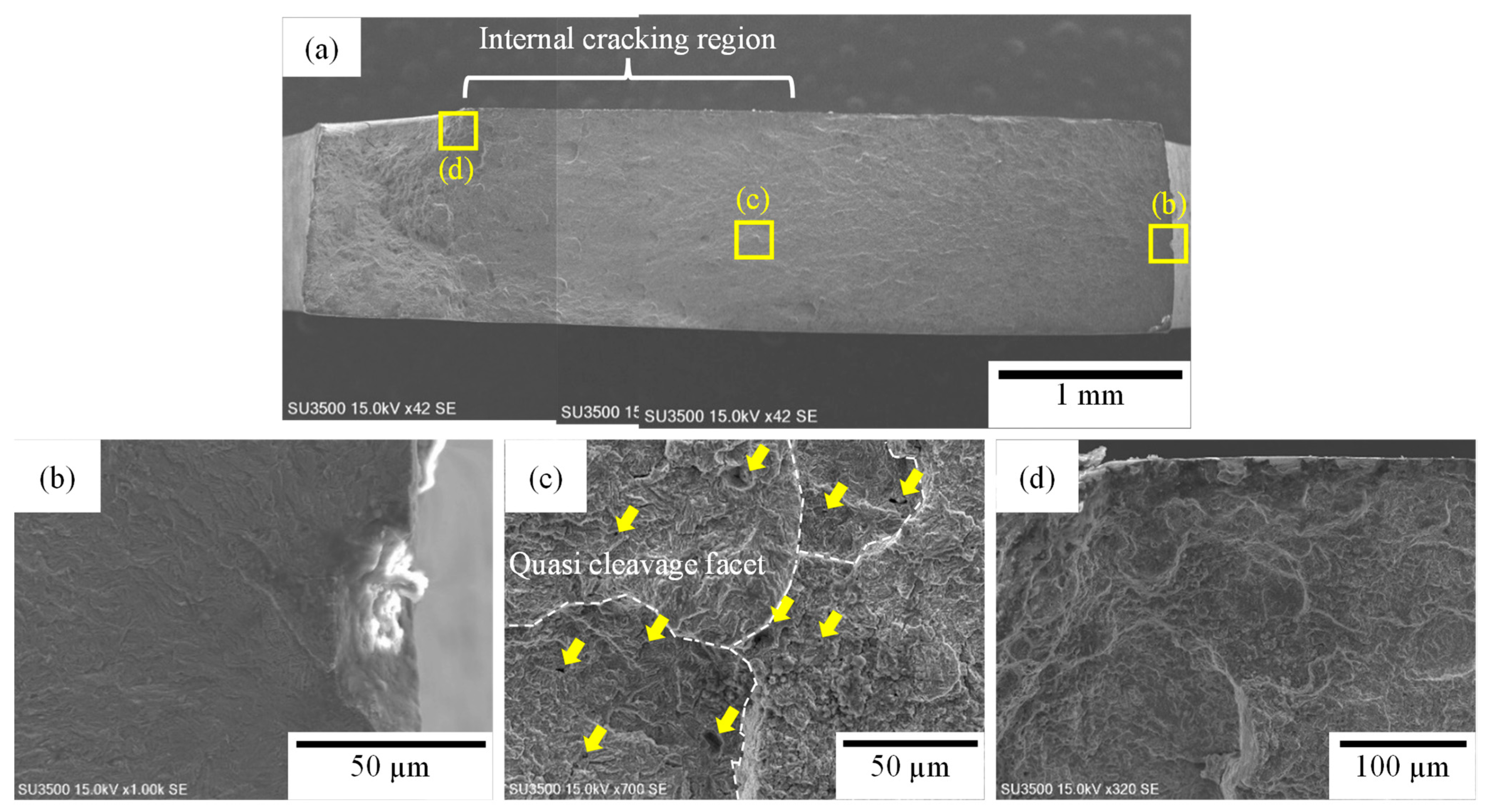
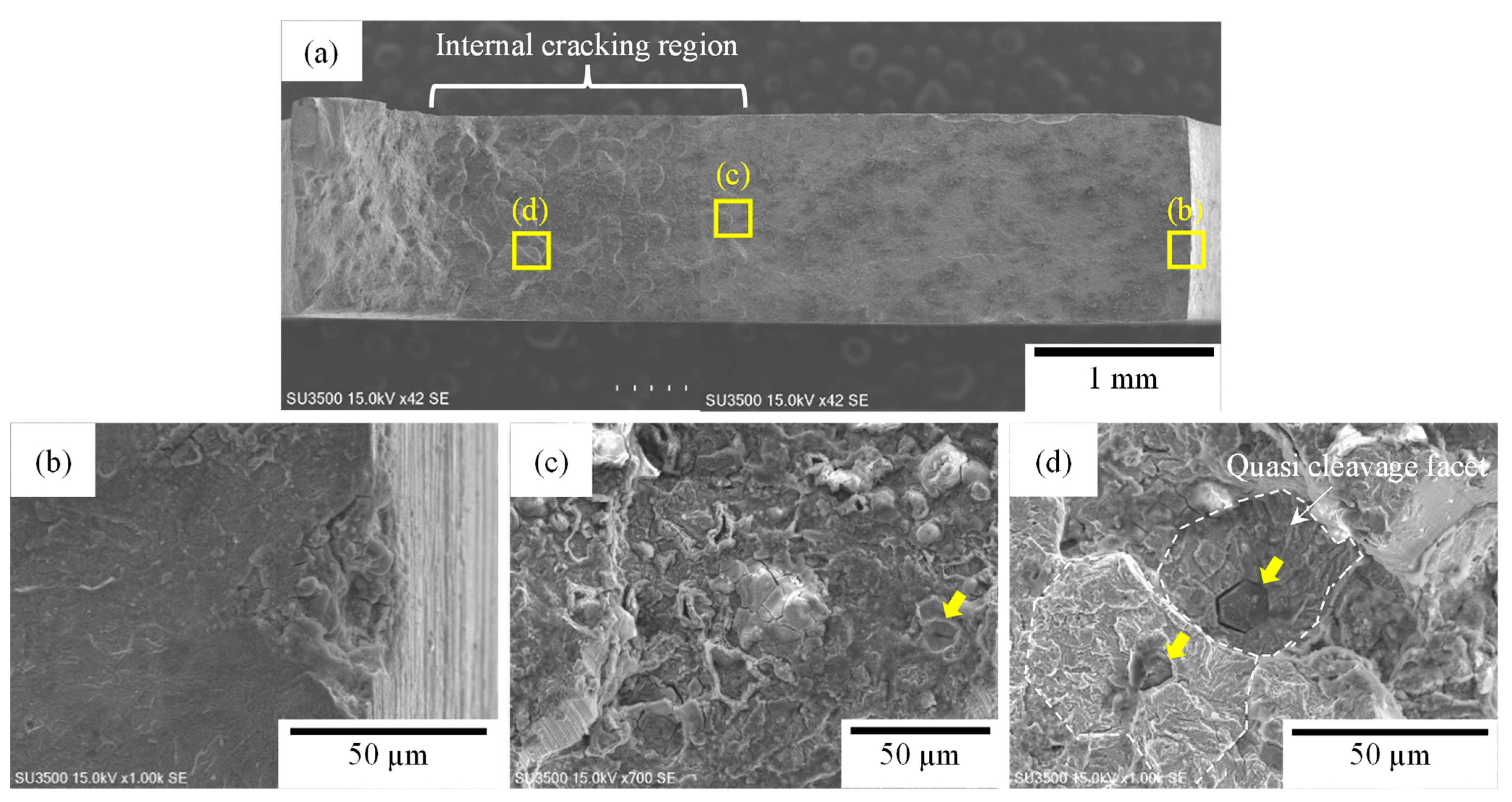
Figure 14 shows the fatigue specimens after the fatigue tests with hydrogen. Fatigue cracks were initiated on one side of the notch root and propagated toward the opposite side before final failure occurred in the TM steels. Figure 15, Figure 16 and Figure 17 show the fracture surfaces of the TM steels after fatigue tests with hydrogen. The magnified SEM images of the notch root around the fatigue crack initiation portion (Figure 15b, Figure 16b and Figure 17b) show that the fatigue crack was initiated at the precipitate and/or matrix/precipitate interface. Within the crack propagation regions of nitrogen-containing TM-B and TM-C steels, new cracks were initiated at the precipitates located inside the specimen, and quasi-cleavage facets evolved around the precipitates, while TM-A steel exhibited a typical fatigue fracture surface (Figure 15c, Figure 16c and Figure 17c). The elemental analysis of the precipitates using EDX suggests it might be AlN. The fracture surfaces in the final fracture region consisted of a mixture of dimples and quasi-cleavages in TM-A, TM-B, and TM-C steels.
3.4. Hydrogen Analysis
The hydrogen evolution curves of the TM steels are shown in Figure 18 [4]. The TM steels exhibited hydrogen desorption from room temperature to approximately 150 °C. The height of the hydrogen desorption peak increased with the nitrogen content, while the hydrogen desorption peak temperature increased slightly with the nitrogen content. The diffusible hydrogen concentrations desorbed below 200 °C were 0.89, 1.53, and 2.72 mass ppm for TM-A, TM-B, and TM-C steels, respectively [4]. It was suggested that hydrogen absorbed in steel is trapped at dislocations [26], in retained austenite and/or matrix/retained austenite interfaces [27,28], and at matrix/precipitate interfaces [29]. In the TM steels, the effects of these factors on the hydrogen-trapping behavior might be small because the martensite matrix morphology and volume fraction of retained austenite were only slightly changed by nitrogen addition. Nitrogen addition to the TM steels resulted in AlN precipitation in the TM steels in which the size of the AlN precipitates increased with the amount of nitrogen [4,7]. Observations of the fracture surface after the fatigue tests with hydrogen indicate that the absorbed hydrogen might be trapped in the AlN precipitates and at the matrix/AlN interfaces because many cracks were present at the AlN precipitates and matrix/AlN interfaces. The increase in diffusible hydrogen content and the increase in the hydrogen desorption peak temperature with the increase in additive nitrogen suggest the role of AlN precipitates acting as hydrogen trap sites with relatively high binding energies compared to the hydrogen traps in the nitrogen-free TM steels.
3.5. Effect of Hydrogen on Fatigue Life
The FL of the TM steels without hydrogen decreased with increasing nitrogen content, as shown in Figure 9 and Figure 10. In contrast, FL did not appear in the TM steels with hydrogen, and Nf at Δσ = 135 MPa decreased with the amount of nitrogen. It was reported that fatigue crack propagation during high-cycle fatigue tests with hydrogen charging was promoted by hydrogen absorption in conventional structural steels such as Cr–Mo and ferrite–perlite steels [30,31]. In this study, it is assumed that the in-depth distribution of hydrogen was homogeneous in the TM steel specimens because hydrogen charging was conducted continuously before and during the fatigue tests. In general, the fatigue crack propagation rate is given by
where a is the crack length, N is the number of cycles, C and m are material-dependent constants, and ΔK is the stress intensity factor range. Matsuoka et al. [20] reported that the crack propagation rates (da/dN) in fatigue tests with hydrogen were increased compared to those in tests in the ambient atmosphere. In TM steels, therefore, fatigue failure presumably occurs at small numbers of cycles in fatigue tests with hydrogen. Moreover, it was reported [7] that crack propagation was suppressed in fatigue tests without hydrogen in TM steels because of stress relaxation due to the martensitic transformation of the retained austenite at the fatigue crack tip. It is expected that the martensitic transformation of highly stable retained austenite suppressed the crack initiation and propagation although hydrogen was absorbed in the TM steels. However, the crack propagation in TRIP-aided steels might be promoted by the accumulation of supersaturated hydrogen around the martensite, which was transformed from retained austenite, owing to the difference between their hydrogen solubilities [32]. These factors may also affect fatigue property degradation in hydrogen-charged TM steels.
da/dN = CΔKm
3.6. Effect of Nitrogen on Fatigue Life and Hydrogen Embrittlement Fracture Behavior
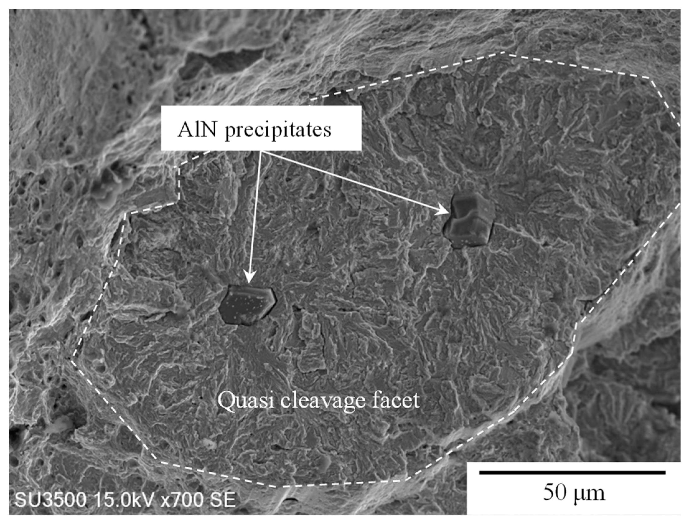
The TM steels with hydrogen charging exhibited lower TEl values compared to those without hydrogen charging (Figure 7). In particular, the TEl of TM-B steel containing 100 ppm nitrogen was remarkably reduced by hydrogen absorption, which resulted in the highest HES (Figure 8). When fatigue tests were carried out at a stress amplitude (Δσ) of 135 MPa with hydrogen, the fatigue lives reflected by the Nf values of nitrogen-containing TM-B and TM-C steels were shorter than that of nitrogen-free TM-A steel. In particular, the Nf of TM-B steel was significantly reduced (Figure 10). AlN precipitation was observed both in TM-B and TM-C steels (Figure 5), although their matrix and retained austenite characteristics were hardly changed by nitrogen addition. Therefore, the martensitic transformation behavior of nitrogen-containing TM steels was presumably similar to that of conventional TM steels [7]. In the tensile specimens, the fracture morphologies near the surfaces of the specimen were changed by hydrogen absorption. Hydrogen promoted crack initiation at the AlN precipitates and matrix/AlN interfaces, and quasi-cleavage facets were observed around the AlN precipitates. However, void initiation due to the high triaxial stress inside the specimens after necking resulted in dimples in TM steels both without and with hydrogen (Figure 11 and Figure 12). It was reported that in TM steel fatigue specimens containing nitrogen without hydrogen [7], fatigue cracks were initiated at the AlN precipitates and/or the matrix/AlN interfaces located near the notch root of the fatigue specimen and propagated along and/or across the martensite laths. New fatigue cracks developed at the AlN precipitates and/or the matrix/AlN interfaces ahead of the crack tip, because the AlN enhanced stress concentration and coalescence of the cracks possibly accelerated fatigue crack propagation in the nitrogen-added TM steels. It is assumed that hydrogen trapping at the AlN precipitates and/or the matrix/AlN interfaces, which is evidenced by the TDS measurements shown in Figure 18, probably promoted the crack initiation. Figure 19 and Figure 20 show typical fracture surfaces in the crack propagation regions of TM-B and TM-C steels after the fatigue tests with hydrogen. In TM-B steel, there were more traces with fine AlN precipitates than in TM-C steel. It is hypothesized that quasi-cleavage cracks were propagated from the fine AlN precipitates, which absorbed a large amount of hydrogen. Notably, the AlN precipitates in TM-C steel (approximately 20 μm in length in the rolling direction) were larger than those in TM-B steel (approximately 5–10 μm in length in the rolling direction), and the quasi-cleavage region had a large area in the former. The AlN precipitate number densities in the nitrogen-containing TM steels were estimated from the SEM images of the fracture surfaces to be 680 pieces/mm2 for TM-B steel and 80 pieces/mm2 for TM-C steel, corresponding to the mean distance between adjacent AlN precipitates of 38.3 μm for TM-B steel and 112 μm for TM-C steel. According to the previous research reported by authors [7], the weight fraction of AlN of the TM-B steel was approximately 0.03 wt. % whereas that of the TM-C steel was approximately 0.06 wt. %, which is double. When it is assumed that the density of AlN was constant and the volume of AlN of the TM-C steel was 23 times larger than that of TM-B steel, the number of AlN precipitates decreased owing to the increase in the weight of AlN due to the increase in the volume of AlN per particle. As shown in Figure 16c and Figure 17d, the number density of the precipitates was larger and the distance between adjacent AlN precipitates was smaller in TM-B steel compared to those in TM-C steel, and these characteristics presumably promoted quasi-cleavage facet coalescence and crack propagation in TM-B steel, resulting in earlier catastrophic failure. In addition, the newly developed crack at the AlN precipitates and/or the matrix/AlN interfaces ahead of the crack tip might also eradicate the fatigue limit of TM steels with hydrogen. In the tensile tests with hydrogen, crack initiation at the AlN precipitates and/or matrix/AlN interfaces, quasi-cleavage facet coalescence, and quasi-cleavage crack propagation were presumably promoted ahead the crack tip. The decreased TEl in the tensile tests and the smaller number of cycles to failure of the nitrogen-added TM steels in the fatigue tests with hydrogen are therefore attributed to the higher number density of the crack initiation site, that is, AlN precipitates and/or matrix/AlN interfaces, and the promoted coalescence of those cracks. It should, however, be noted that voids were initiated inside the specimens at regions of high triaxial stress in tensile specimens both with and without hydrogen, and that the initial fatigue cracks in fatigue tests both with and without hydrogen were initiated at the AlN precipitates and/or matrix/AlN interfaces at the notch root.
4. Conclusions
The tensile and fatigue properties of nitrogen-added TM steels with hydrogen and the tensile and fatigue crack propagation behaviors of these steels with hydrogen were investigated to improve the fatigue properties and hydrogen embrittlement resistance of advanced ultra-high-strength steel sheets. The main results are summarized as follows:
(1) The microstructure of TM steel consisted of a martensite matrix and fine retained austenite. Although nitrogen addition did not significantly change the morphology of the martensite matrix and retained austenite characteristics, coarse AlN precipitates were formed in the martensite matrix when nitrogen was added at the concentrations of 100 and 200 ppm. The size of the AlN precipitates in the TM steel with 200 ppm of nitrogen was larger than that in the TM steel containing 100 ppm nitrogen, whereas the number density of AlN precipitates was larger in the latter;
(2) The total elongation of each TM steel decreased after hydrogen charging. In particular, the TM steel containing 100 ppm nitrogen exhibited a significant decrease in total elongation following hydrogen charging, and showed high hydrogen embrittlement susceptibility compared to the other TM steels;
(3) The fatigue limit of the hydrogen-uncharged TM steels decreased from 270 to 252 MPa as the amount of nitrogen increased. The apparent fatigue limit was not exhibited in the hydrogen-charged TM steels in the range of the stress amplitude in this study, whose minimum was 135 MPa. The number of cycles to failure in the hydrogen-charged TM steels containing 100 ppm nitrogen was less than those of the other TM steels;
(4) In the hydrogen-charged TM steels, quasi-cleavage facets were initiated around the AlN precipitates in the crack propagation regions of the tensile and fatigue specimens. The number density of AlN precipitates, which caused quasi-cleavage fracturing in the TM steel with 100 ppm nitrogen, was larger than that in the TM steel with 200 ppm nitrogen, although the AlN precipitates in the former were smaller;
(5) The increased susceptibility to hydrogen embrittlement in tensile tests and the reduced number of cycles to failure at a stress amplitude of 135 MPa in fatigue tests for TM steels containing 100 ppm nitrogen can be attributed to the precipitation of AlN precipitates with a high number density, which promoted the quasi-cleavage crack coalescence.
Author Contributions
Conceptualization, T.H. and A.N.; methodology, T.H. and A.N.; validation, T.H., A.N., E.A. and J.K.; formal analysis, T.H., J.K. and Y.S.; investigation, T.H., A.N., J.K. and Y.S.; writing—original draft preparation, T.H. and A.N.; writing—review and editing, T.H., A.N. and E.A.; project administration, T.H. and A.N.; funding acquisition, E.A., T.H. and A.N. All authors have read and agreed to the published version of the manuscript.
Funding
The authors gratefully acknowledge the financial support obtained through grants from The Iron and Steel Institute of Japan (2012). Parts of this work were financially supported by The Amada Foundation, No. AF-2020002-A3 and National Institute of Technology (KOSEN), Nagano College Foundation. Also, this work was performed under the GIMRT Program of the Institute for Materials Research, Tohoku University (Proposal Nos. 19K0032 and 20K0002).
Data Availability Statement
The original contributions presented in the study are included in the article, further inquiries can be directed to the corresponding author.
Acknowledgments
We would like to thank Zulhafiz Bin Zolkepeli and Kohei Terashima at National Institute of Technology (KOSEN), Nagano College.
Conflicts of Interest
The authors declare no conflicts of interest.
References
- Zackay, V.F.; Parker, E.R.; Fahr, D.; Bush, R. The enhancement of ductility in high-strength steels. Trans. Am. Soc. Met. 1967, 60, 252–259. [Google Scholar]
- Matsuyama, S. Delayed Fracture of High Strength Steels. Tetsu-To-Hagané 1994, 80, 679–684. [Google Scholar] [CrossRef]
- Mukherjee, M.; Mohanty, O.N.; Hashimoto, S.; Hojo, T.; Sugimoto, K. Strain-induced Transformation Behaviour of Retained Austenite and Tensile Properties of TRIP-aided Steels with Different Matrix Microstructure. ISIJ Int. 2006, 46, 316–324. [Google Scholar] [CrossRef]
- Hojo, T.; Chanvichitkul, K.; Waki, H.; Nishimura, F.; Akiyama, E. Hydrogen embrittlement properties of nitrogen added ultra-high-strength TRIP-aided martensitic steels evaluated by using conventional strain rate technique. Procedia Manuf. 2018, 15, 1581–1587. [Google Scholar] [CrossRef]
- Hojo, T.; Kikuchi, R.; Waki, H.; Nishimura, F.; Ukai, Y.; Akiyama, E. Effect of Strain Rate on the Hydrogen Embrittlement Property of Ultra High-strength Low Alloy TRIP-aided Steel. ISIJ Int. 2018, 58, 751–759. [Google Scholar] [CrossRef]
- Nagasaka, A.; Hojo, T.; Shibayama, Y.; Fujita, M.; Ohashi, T.; Miyasaka, M.; Akiyama, E. V-Bendability of Ultrahigh-Strength Low Alloy TRIP-Aided Steel Sheets with Bainitic Ferrite Matrix. ISIJ Int. 2022, 62, 247–256. [Google Scholar] [CrossRef]
- Hojo, T.; Kobayashi, J.; Sugimoto, K.; Takemoto, Y.; Nagasaka, A.; Koyama, M.; Akiyama, E. Effects of Matrix Structure and Nitrogen Content on Fatigue Properties of Ultrahigh-Strength Low Alloy TRIP-Aided Steels. ISIJ Int. 2021, 61, 591–598. [Google Scholar] [CrossRef]
- Hojo, T.; Kobayashi, J.; Sugimoto, K. Impact properties of low-alloy transformation-induced plasticity-steels with different matrix. Mater. Scie. Technol. 2016, 32, 1035–1042. [Google Scholar] [CrossRef]
- Bahrami, F.; Hendry, A. Microstructure and mechanical behaviour of nitrogen alloyed martensitic stainless steel. Mater. Sci. Technol. 2013, 11, 488–497. [Google Scholar] [CrossRef]
- Ono, A.A.; Alonso, N.; Tschiptsch, A.P. The Corrosion Resistance of Nitrogen Bearing Martensitic Stainless Steels. ISIJ Int. 1996, 36, 813–817. [Google Scholar] [CrossRef]
- Grabke, H.J. The Role of Nitrogen in the Corrosion of Iron and Steels. ISIJ Int. 1996, 36, 777–786. [Google Scholar] [CrossRef]
- Kim, K.S.; Kang, J.H.; Kim, S.J. Nitrogen effect on hydrogen diffusivity and hydrogen embrittlement behavior in austenitic stainless steels. Scr. Mater. 2020, 184, 70–73. [Google Scholar] [CrossRef]
- Luo, Y.; Li, W.; Jiang, L.; Zhong, N.; Jin, X. Hydrogen embrittlement and hydrogen diffusion behavior in interstitial nitrogen-alloyed austenitic steel. Int. J. Hydrog. Energy 2021, 46, 32710–32722. [Google Scholar] [CrossRef]
- Murakami, Y.; Endo, M. Effects of defects, inclusions and inhomogeneities on fatigue strength. Int. J. Fatigue 1994, 16, 163–182. [Google Scholar] [CrossRef]
- Matsunaga, H.; Yoshikawa, M.; Kondo, R.; Yamabe, J.; Matsuoka, S. Slow strain rate tensile and fatigue properties of Cr–Mo and carbon steels in a 115 MPa hydrogen gas atmosphere. Int. J. Hydrog. Energy 2015, 40, 5739–5748. [Google Scholar] [CrossRef]
- Macadre, A.; Yano, H.; Matsuoka, S.; Furtado, J. The effect of hydrogen on the fatigue life of Ni–Cr–Mo steel envisaged for use as a storage cylinder for a 70 MPa hydrogen station. Int. J. Fatigue 2011, 33, 1608–1619. [Google Scholar] [CrossRef]
- Aoki, Y.; Kawamoto, K.; Oda, Y.; Noguchi, H.; Higashida, K. Fatigue characteristics of a type 304 austenitic stainless steel in hydrogen gas environment. Int. J. Fract. 2005, 133, 277–288. [Google Scholar] [CrossRef]
- Nakamura, M.; Okazaki, S.; Matsunaga, H.; Matsuoka, S. SSRT and fatigue life properties of austenitic stainless steel weld metal 317L in high-pressure hydrogen gas. Trans. JSME 2018, 84, 17–00437. [Google Scholar] [CrossRef]
- Murakami, Y.; Kanezaki, T.; Mine, Y.; Matsuoka, S. Hydrogen Embrittlement Mechanism in Fatigue of Austenitic Stainless Steels. Metall. Mater. Trans. A 2008, 39, 1327–1339. [Google Scholar] [CrossRef]
- Matsuoka, S.; Tanaka, H.; Homma, N.; Murakami, Y. Influence of hydrogen and frequency on fatigue crack growth behavior of Cr-Mo steel. Int. J. Fract. 2010, 168, 101–112. [Google Scholar] [CrossRef]
- Fernández-Sousa, R.; Betegón, C.; Martínez-Pañeda, E. Analysis of the influence of microstructural traps on hydrogen assisted fatigue. Acta Mater. 2020, 199, 253–263. [Google Scholar] [CrossRef]
- Gao, G.; Liu, R.; Wang, K.; Gui, X.; Misra, R.D.K.; Bai, B. Role of retained austenite with different morphologies on sub-surface fatigue crack initiation in advanced bainitic steels. Scr. Mater. 2020, 184, 12–18. [Google Scholar] [CrossRef]
- Malitckii, E.; Yagodzinskyy, Y.; Vilaça, P. Role of retained austenite in hydrogen trapping and hydrogen-assisted fatigue fracture of high-strength steels. Mater. Sci. Eng. A 2019, 760, 68–75. [Google Scholar] [CrossRef]
- Tamura, I. Steel Material Study on the Strength; Nikkan-Kogyo Shinbun Ltd.: Tokyo, Japan, 1970. [Google Scholar]
- Maruyama, H. X-ray measurement of retained austenite volume fraction. J. Jpn. Soc. Heat Treat. 1977, 17, 198–204. [Google Scholar]
- Bhadeshia, H.K.D.H. Prevention of Hydrogen Embrittlement in Steels. ISIJ Int. 2016, 56, 24–36. [Google Scholar] [CrossRef]
- Gu, J.; Chang, K.; Fang, H.S.; Bai, B. Delayed Fracture Properties of 1500 MPa Bainite/Martensite Dual-phase High Strength Steel and Its Hydrogen Traps. ISIJ Int. 2002, 42, 1560–1564. [Google Scholar] [CrossRef]
- Chan, S.L.I.; Lee, H.L.; Yang, J.R. Effect of retained austenite on the hydrogen content and effective diffusivity of martensitic structure. Metall. Trans. A 1991, 22, 2579–2586. [Google Scholar] [CrossRef]
- Nagao, A.; Hayashi, K.; Oi, K.; Mitao, S. Effect of Uniform Distribution of Fine Cementite on Hydrogen Embrittlement of Low Carbon Martensitic Steel Plates. ISIJ Int. 2012, 52, 213–221. [Google Scholar] [CrossRef]
- Sasaki, D.; Koyama, M.; Noguchi, H. Influence of Stress Re-distribution on Hydrogen-induced Fatigue Crack Propagation. ISIJ Int. 2019, 59, 1683–1690. [Google Scholar] [CrossRef]
- Matsuoka, S.; Yamabe, J.; Matsunaga, H. Criteria for determining hydrogen compatibility and the mechanisms for hydrogen-assisted surface crack growth in austenitic stainless steels. Eng. Fract. Mech. 2016, 153, 103–127. [Google Scholar] [CrossRef]
- Hojo, T.; Koyama, M.; Terao, N.; Tsuzaki, K.; Akiyama, E. Transformation-assisted hydrogen desorption during deformation in steels: Examples of α′- and ε-Martensite. Int. J. Hydrog. Energy 2019, 44, 30472–30477. [Google Scholar] [CrossRef]
Figure 1.
Heat treatment diagram of annealing and isothermal transformation treatment processes for TM steels, in which “RT” and “O.Q.” represent room temperature and quenching in oil, respectively.
Figure 1.
Heat treatment diagram of annealing and isothermal transformation treatment processes for TM steels, in which “RT” and “O.Q.” represent room temperature and quenching in oil, respectively.

Figure 2.
Dimensions of (a) tensile test and (b) fatigue test specimens [7]. The unit for these specimens is mm.
Figure 2.
Dimensions of (a) tensile test and (b) fatigue test specimens [7]. The unit for these specimens is mm.

Figure 3.
Arrangements of (a) hydrogen charging and (b) fatigue test with hydrogen charging.
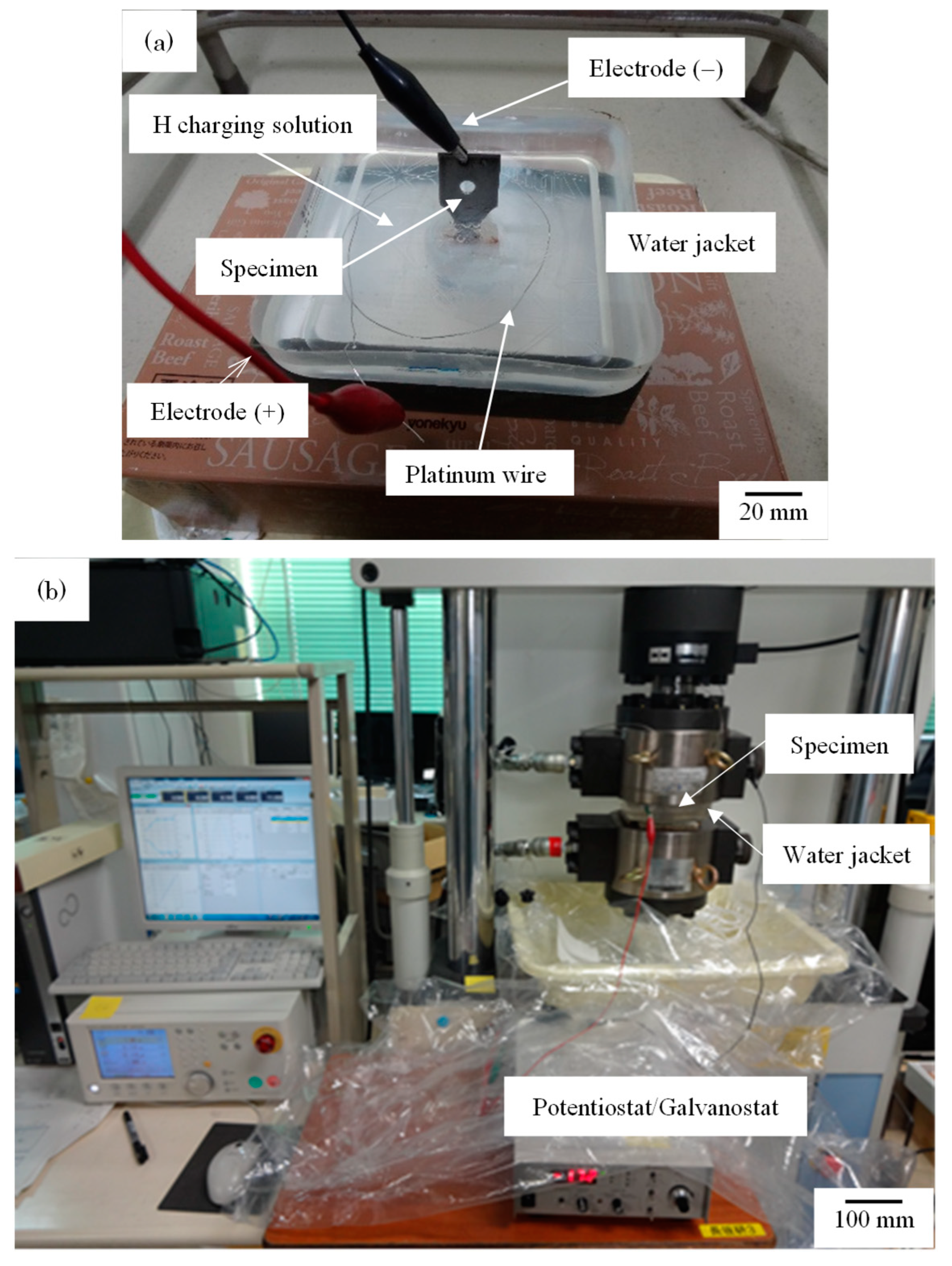
Figure 4.
(a,c,e) Scanning electron micrographs and (b,d,f) transmission electron micrographs of (a,b) TM-A, (c,d) TM-B and (e,f) TM-C steels.
Figure 4.
(a,c,e) Scanning electron micrographs and (b,d,f) transmission electron micrographs of (a,b) TM-A, (c,d) TM-B and (e,f) TM-C steels.
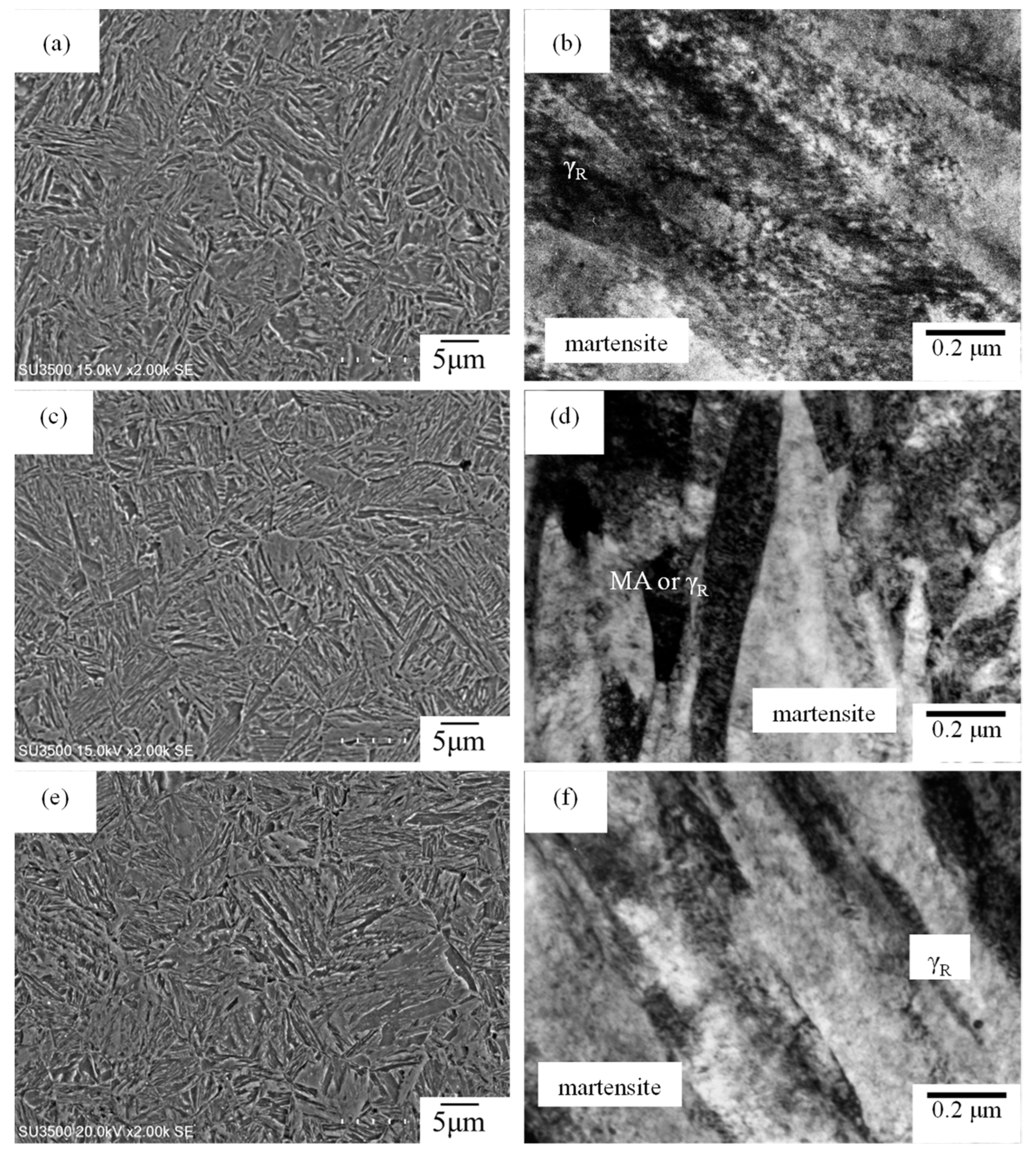
Figure 5.
(a,c,e) Band contrast and (b,d,f) phase maps of (a,b) TM-A, (c,d) TM-B and (e,f) TM-C steels.
Figure 5.
(a,c,e) Band contrast and (b,d,f) phase maps of (a,b) TM-A, (c,d) TM-B and (e,f) TM-C steels.
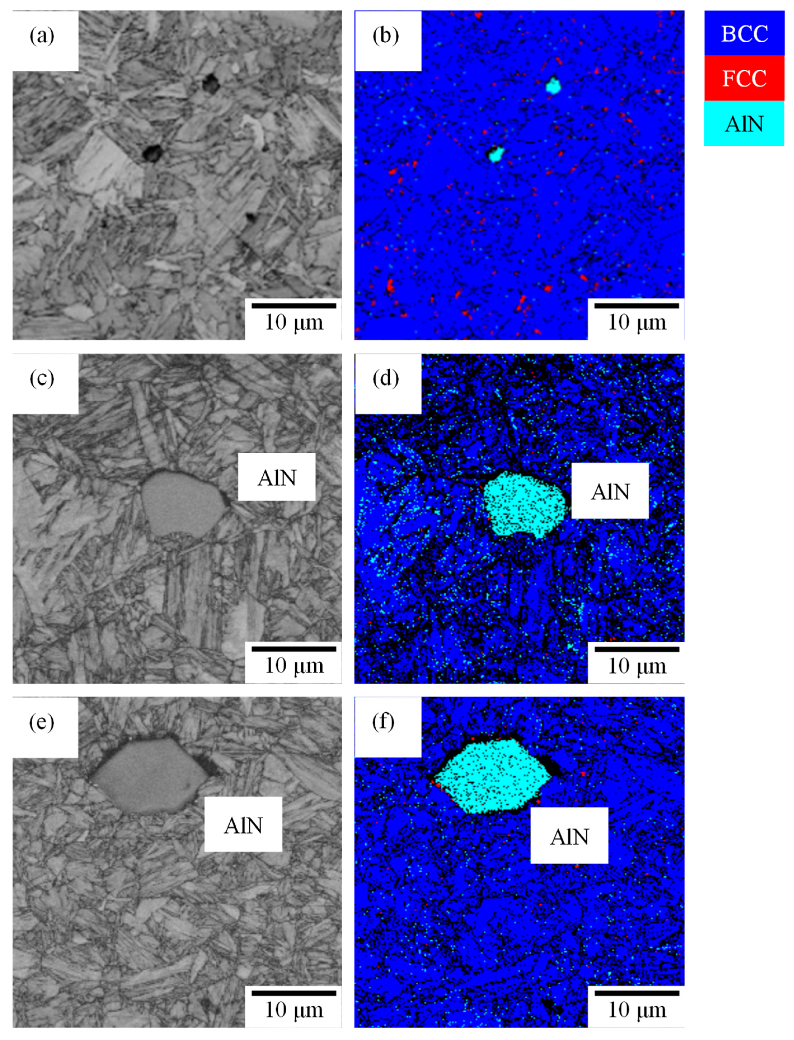
Figure 6.
Nominal stress—strain curves of (a) TM-A, (b) TM-B and (c) TM-C steels without and with hydrogen.
Figure 6.
Nominal stress—strain curves of (a) TM-A, (b) TM-B and (c) TM-C steels without and with hydrogen.
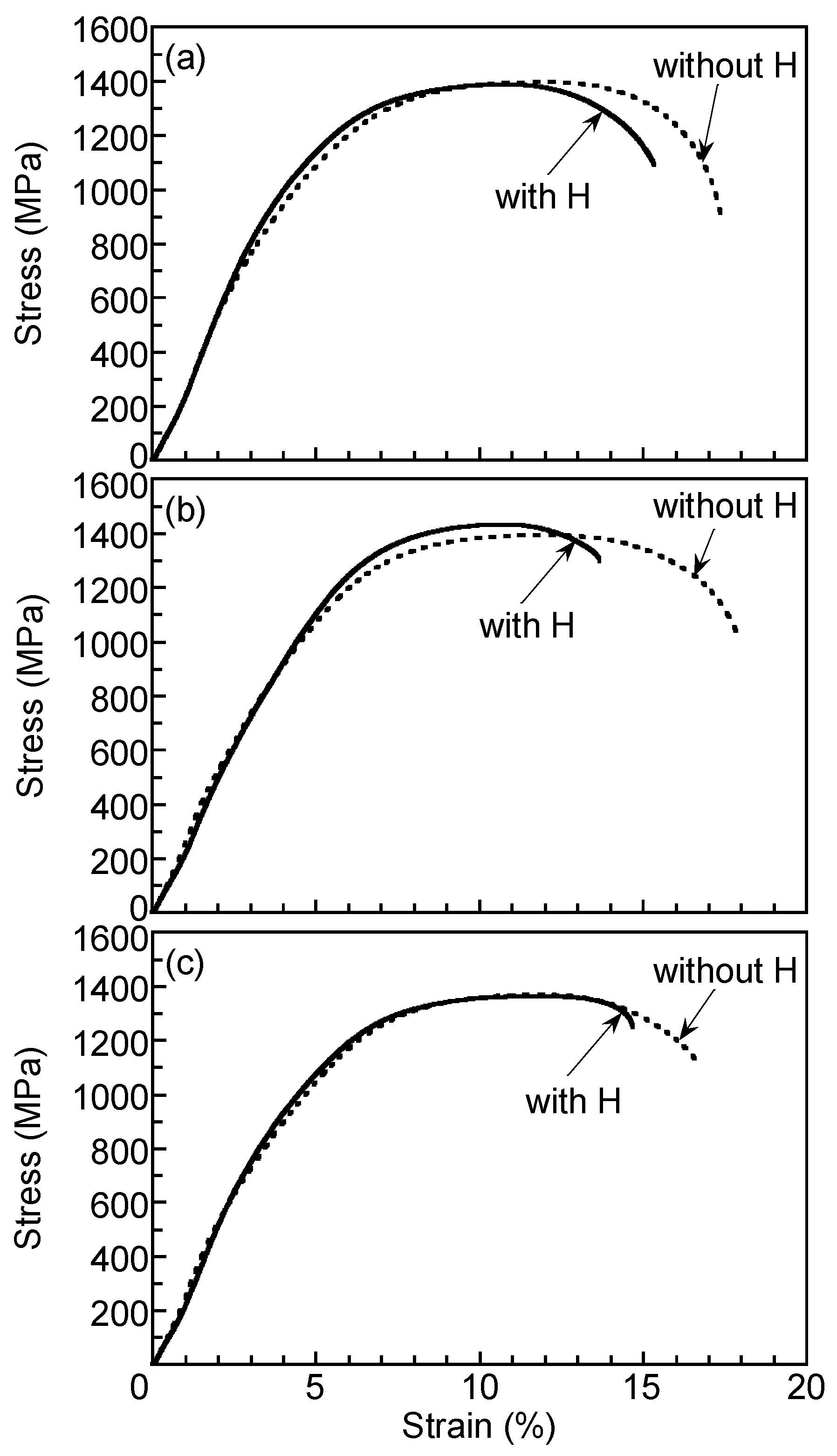
Figure 7.
Comparisons of (a) tensile strength (TS) and (b) total elongation (TEl) of nitrogen-added TM steels without and with hydrogen.
Figure 7.
Comparisons of (a) tensile strength (TS) and (b) total elongation (TEl) of nitrogen-added TM steels without and with hydrogen.
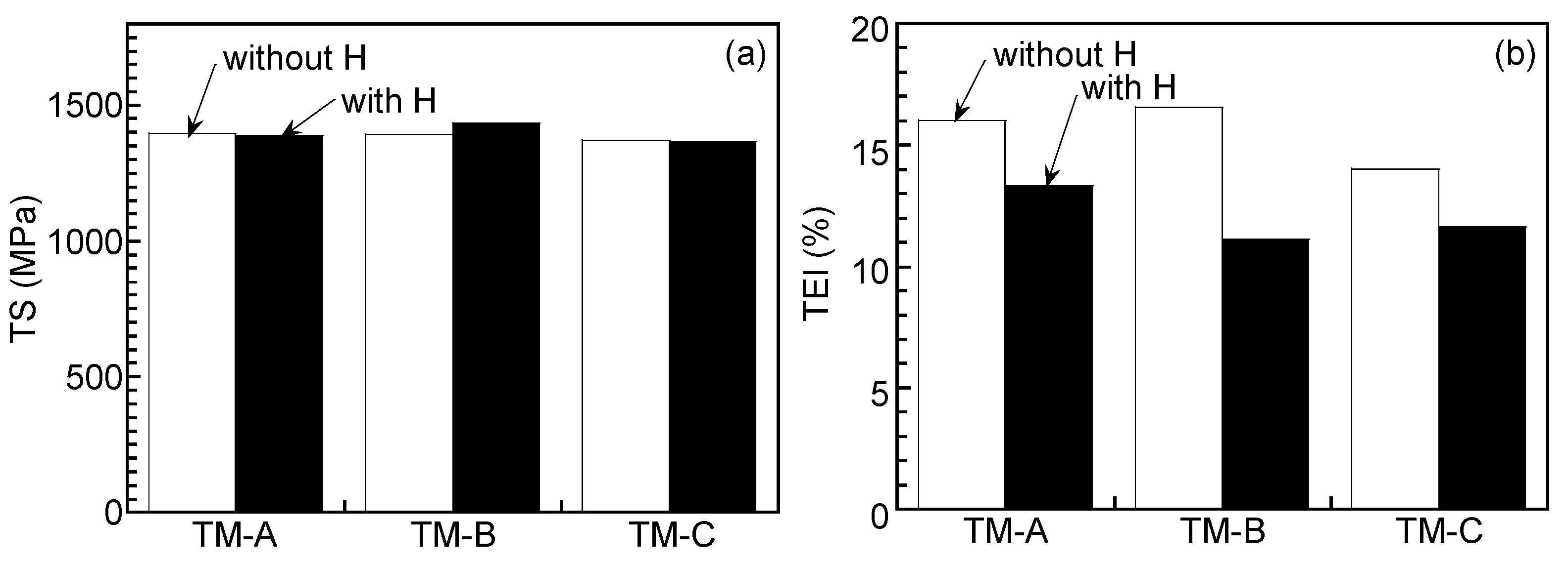
Figure 8.
Hydrogen embrittlement susceptibility (HES) of nitrogen-added TM steels.
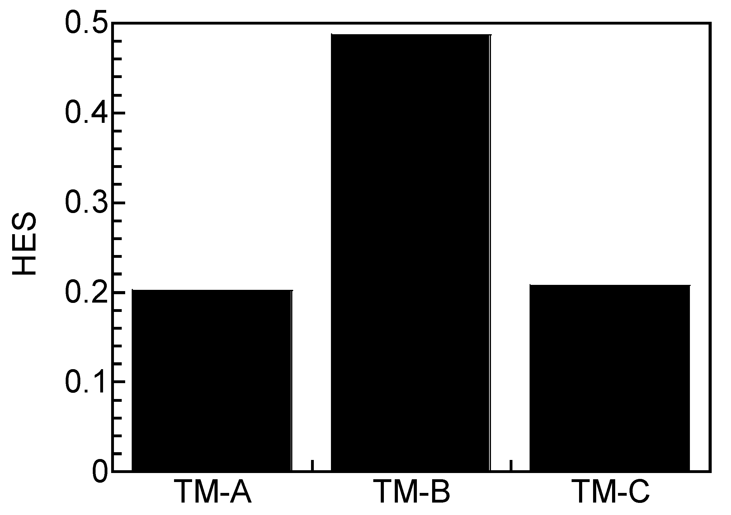
Figure 9.
S-N curves of (a) TM-A, (b) TM-B and (c) TM-C steels without and with hydrogen charging [7].
Figure 9.
S-N curves of (a) TM-A, (b) TM-B and (c) TM-C steels without and with hydrogen charging [7].
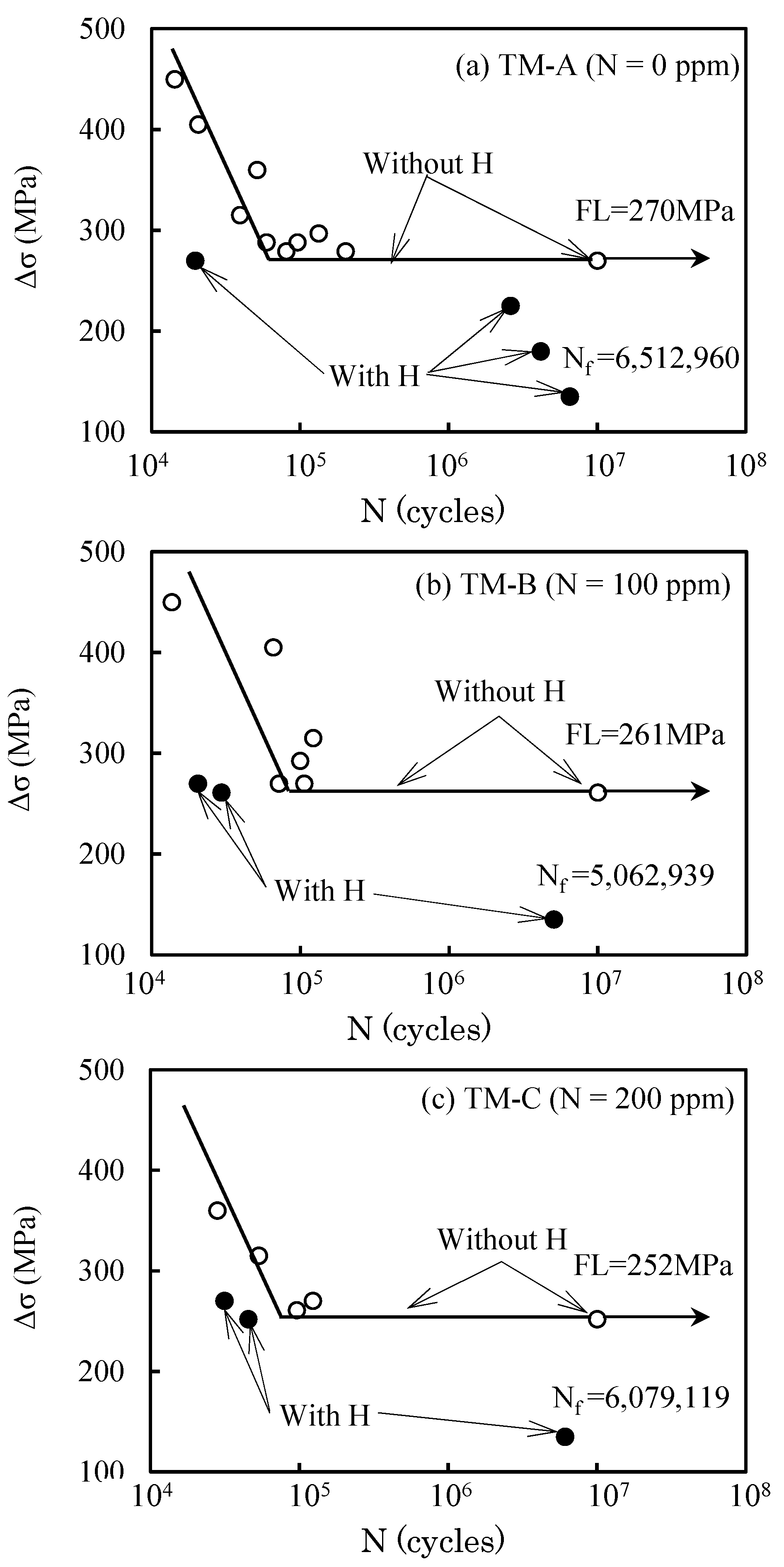
Figure 10.
Comparisons of (a) fatigue limit (FL) without hydrogen and (b) number of cycles to failure (Nf) with hydrogen charging (Δσ = 135 MPa, σmax = 300 MPa, σmin = 30 MPa) [7].
Figure 10.
Comparisons of (a) fatigue limit (FL) without hydrogen and (b) number of cycles to failure (Nf) with hydrogen charging (Δσ = 135 MPa, σmax = 300 MPa, σmin = 30 MPa) [7].
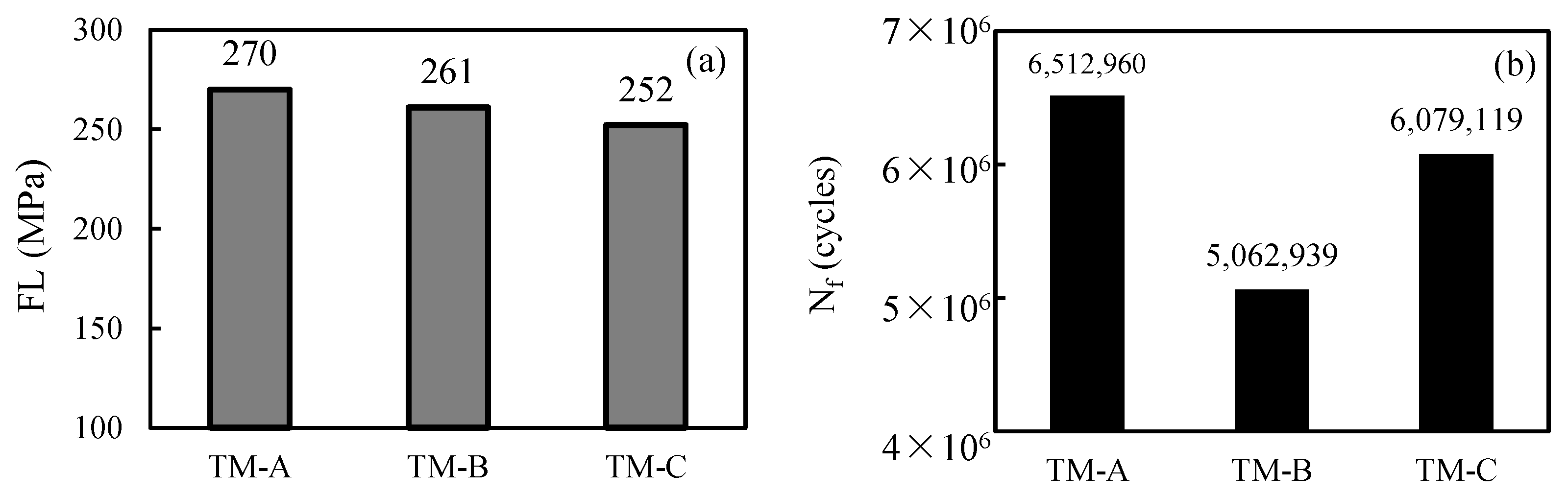
Figure 11.
Fracture surfaces at (a,c,e) the center and (b,d,f) near the edge of tensile-tested (a,b) TM-A, (c,d) TM-B and (e,f) TM-C steels without hydrogen charging.
Figure 11.
Fracture surfaces at (a,c,e) the center and (b,d,f) near the edge of tensile-tested (a,b) TM-A, (c,d) TM-B and (e,f) TM-C steels without hydrogen charging.

Figure 12.
Fracture surfaces at (a,c,e) the center and (b,d,f) near the edge of tensile-tested (a,b) TM-A, (c,d) TM-B and (e,f) TM-C steels with hydrogen charging. Yellow arrows in (d,f) represent AlN or traces of AlN.
Figure 12.
Fracture surfaces at (a,c,e) the center and (b,d,f) near the edge of tensile-tested (a,b) TM-A, (c,d) TM-B and (e,f) TM-C steels with hydrogen charging. Yellow arrows in (d,f) represent AlN or traces of AlN.
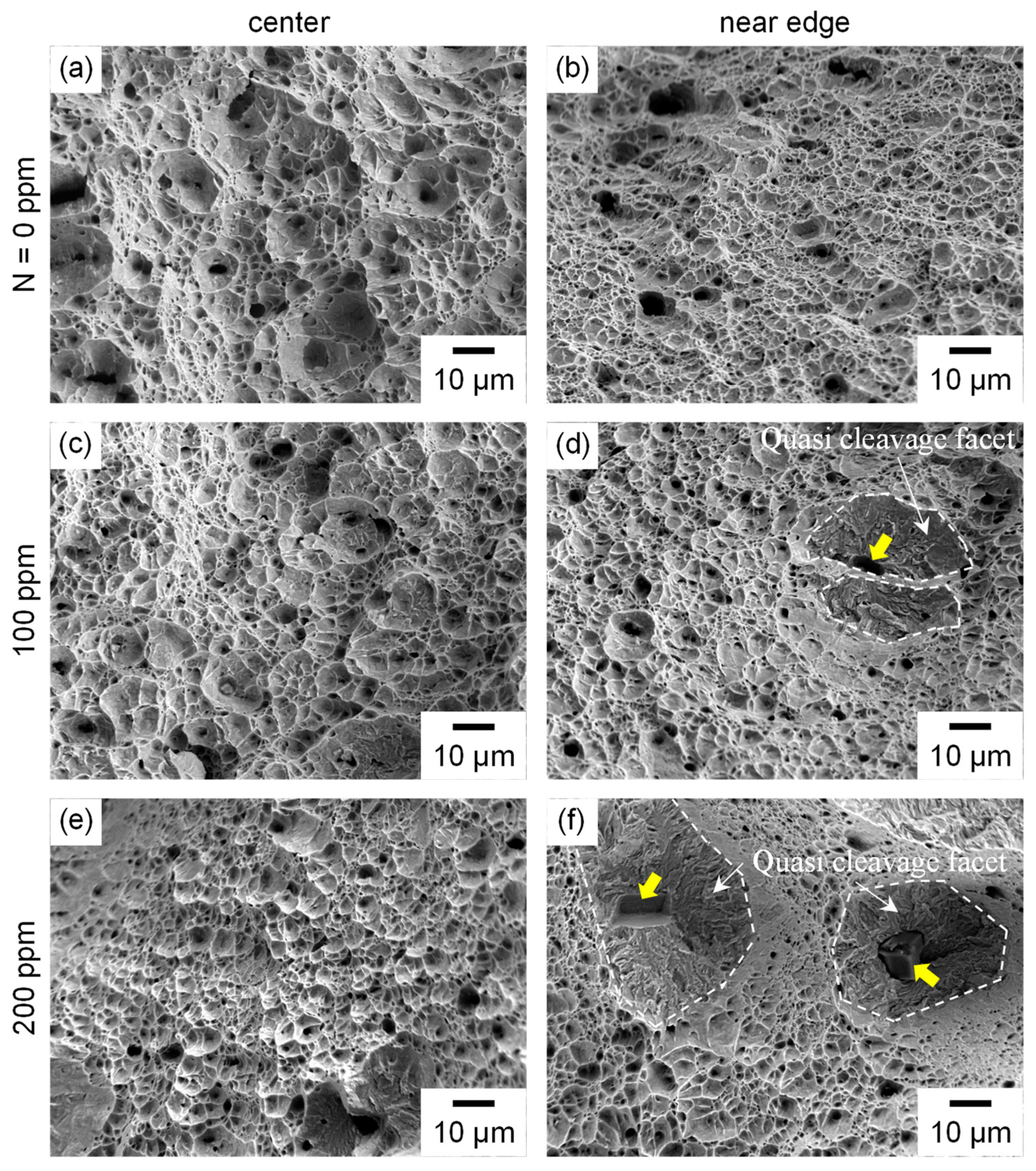
Figure 13.
(a) Fracture surface and (b) energy-dispersive X-ray spectroscopy (EDX) analysis of the precipitate on the fracture surface in TM-C steel without hydrogen charging.
Figure 13.
(a) Fracture surface and (b) energy-dispersive X-ray spectroscopy (EDX) analysis of the precipitate on the fracture surface in TM-C steel without hydrogen charging.

Figure 14.
Fatigue specimens after fatigue tests with hydrogen charging for (a) TM-A, (b) TM-B and (c) TM-C steels. Yellow arrows represent the crack propagation direction.
Figure 14.
Fatigue specimens after fatigue tests with hydrogen charging for (a) TM-A, (b) TM-B and (c) TM-C steels. Yellow arrows represent the crack propagation direction.

Figure 15.
Fracture surfaces of fatigue-tested TM-A steel with hydrogen charging. (a) Low-magnification image, (b) magnified image of crack initiation region at (b) in (a), (c) magnified image of crack propagation region at (c) in (a), (d) magnified image of final fracture region at (d) in (a).
Figure 15.
Fracture surfaces of fatigue-tested TM-A steel with hydrogen charging. (a) Low-magnification image, (b) magnified image of crack initiation region at (b) in (a), (c) magnified image of crack propagation region at (c) in (a), (d) magnified image of final fracture region at (d) in (a).
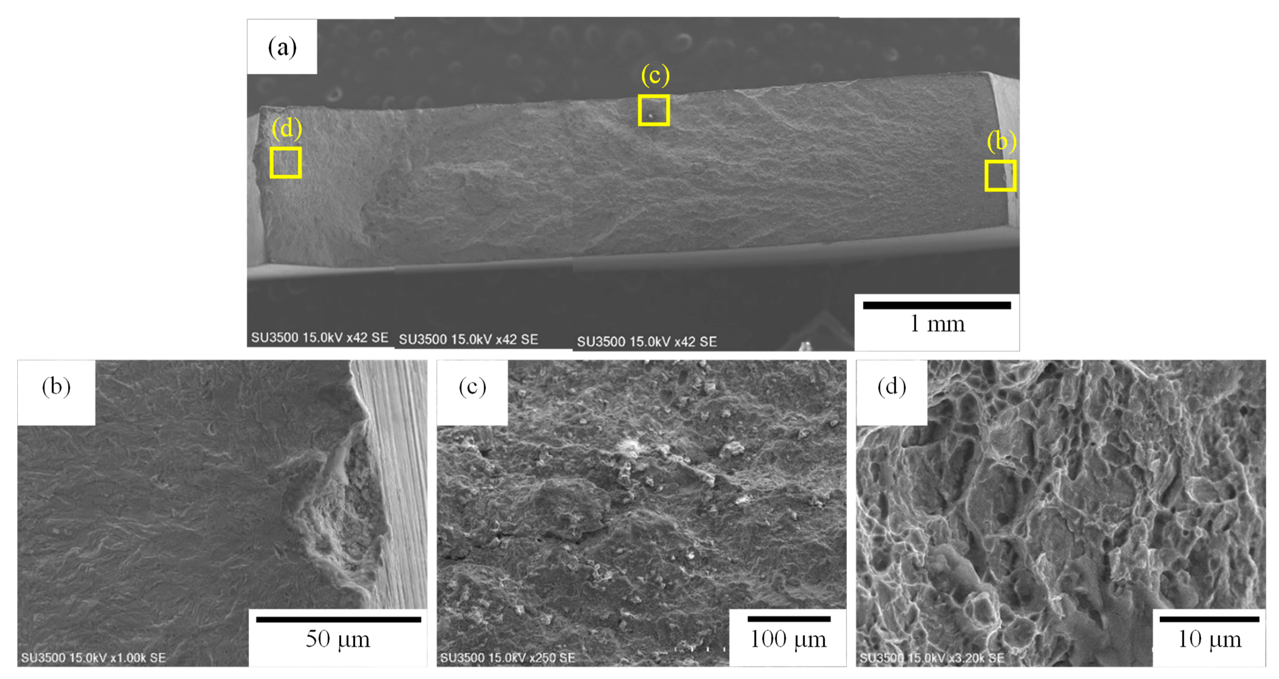
Figure 16.
Fracture surfaces of fatigue-tested TM-B steel with hydrogen charging. (a) Low-magnification image, (b) magnified image of crack initiation region at (b) in (a), (c) magnified image of internal crack initiation region at (c) in (a), (d) magnified image of final fracture region at (d) in (a). Yellow arrows in (c) represent AlN or trace of AlN.

Figure 17.
Fracture surfaces of fatigue-tested TM-C steel with hydrogen charging. (a) Low-magnification image, (b) magnified image of crack initiation region at (b) in (a), (c) magnified image of internal crack initiation region at (c) in (a), (d) magnified image of internal crack initiation region at (d) in (a). Yellow arrows in (c) and (d) represent AlN or trace of AlN.

Figure 18.
Hydrogen desorption curves of TM steels [4]. HD denotes diffusible hydrogen concentration.
Figure 18.
Hydrogen desorption curves of TM steels [4]. HD denotes diffusible hydrogen concentration.
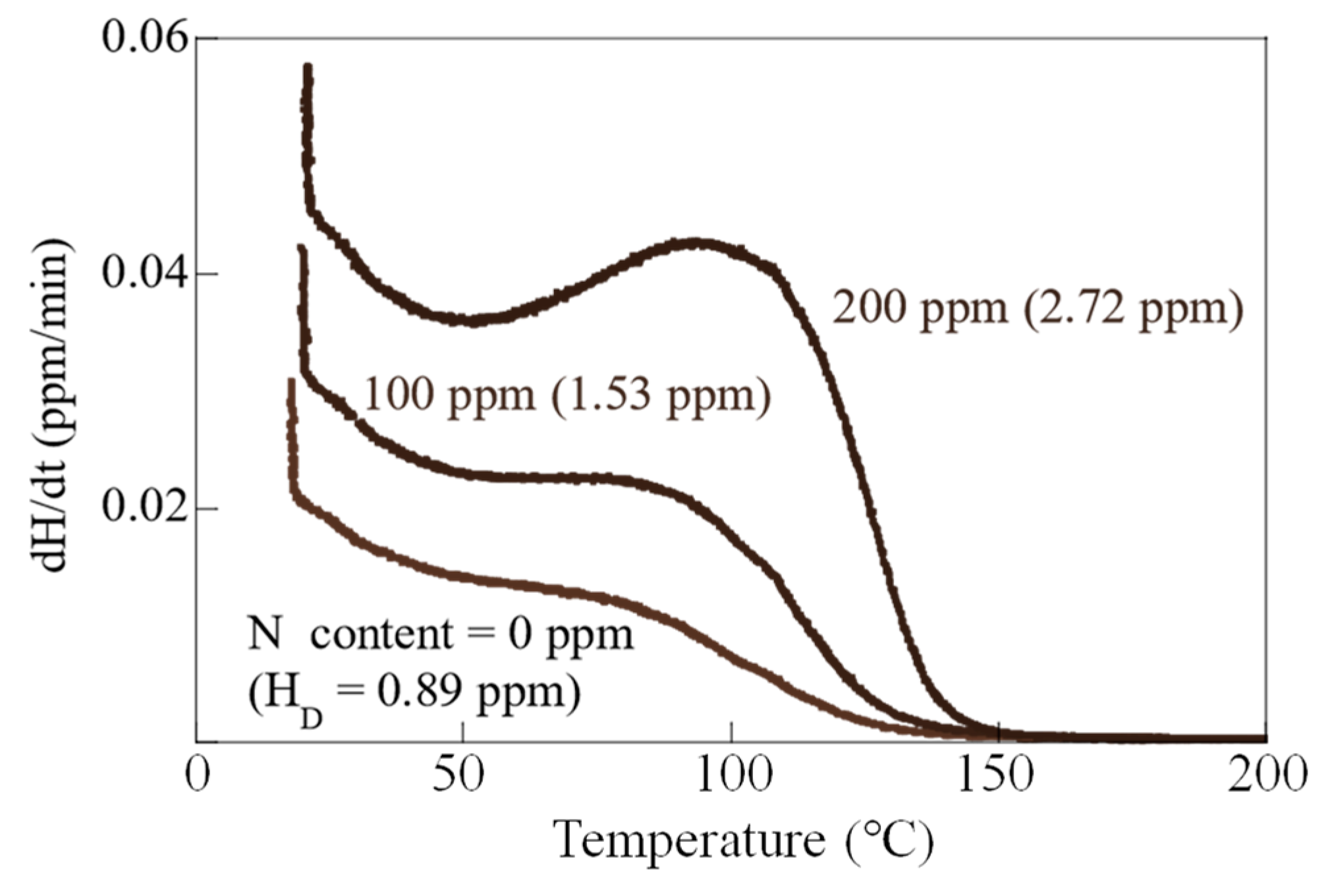
Figure 19.
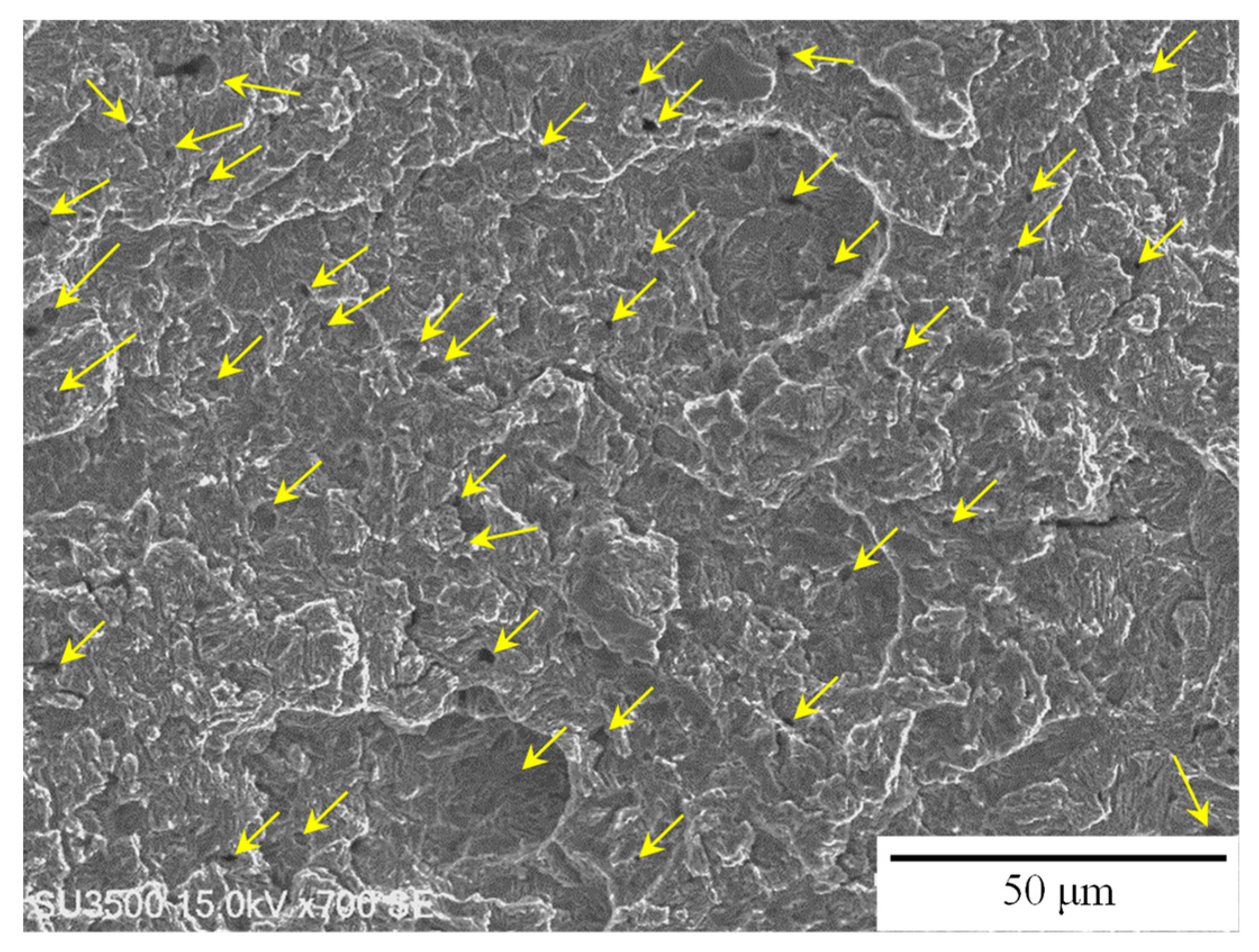
Fracture surface of internal crack initiation region at AlN or trace of AlN of fatigue-tested TM-B steel with hydrogen. Yellow arrows represent traces of AlN. The density of AlN precipitation was 680 pieces/mm2.
Figure 19.
Fracture surface of internal crack initiation region at AlN or trace of AlN of fatigue-tested TM-B steel with hydrogen. Yellow arrows represent traces of AlN. The density of AlN precipitation was 680 pieces/mm2.

Figure 20.
Fracture surface of internal crack initiation region at AlN of fatigue-tested TM-C steel with hydrogen. The density of AlN precipitation was 80 pieces/mm2.
Figure 20.
Fracture surface of internal crack initiation region at AlN of fatigue-tested TM-C steel with hydrogen. The density of AlN precipitation was 80 pieces/mm2.

Table 1.
Chemical composition of steels used (mass%).
| Steel | C | Si | Mn | Al | Nb | N | Fe | Ms (°C) |
|---|---|---|---|---|---|---|---|---|
| A | 0.200 | 1.00 | 1.50 | 0.48 | 0.049 | 0.0009 | Bal. | 434 |
| B | 0.187 | 1.01 | 1.50 | 0.48 | 0.050 | 0.0106 | Bal. | 438 |
| C | 0.176 | 1.04 | 1.50 | 0.53 | 0.052 | 0.0188 | Bal. | 444 |
MS: martensite-transformation-start temperature.
Table 2.
Retained austenite characteristics [7] and mechanical properties of TM steels without hydrogen.
Table 2.
Retained austenite characteristics [7] and mechanical properties of TM steels without hydrogen.
| Steel | fγ0 | Cγ0 | TS | YS | TEl | UEl | FL |
|---|---|---|---|---|---|---|---|
| TM-A | 3.0 | 0.62 | 1396 | 1111 | 16.0 | 6.7 | 270 |
| TM-B | 3.0 | 0.63 | 1393 | 1102 | 16.5 | 6.6 | 261 |
| TM-C | 3.2 | 0.85 | 1369 | 1083 | 14.0 | 6.9 | 252 |
fγ0 (vol%): initial volume fraction of retained austenite. Cγ0 (mass%): initial carbon concentration in retained austenite. TS (MPa): tensile strength. YS (MPa): yield stress or 0.2% offset proof stress. TEl (%): total elongation. UEl (%): uniform elongation. FL (MPa): fatigue limit.
Disclaimer/Publisher’s Note: The statements, opinions and data contained in all publications are solely those of the individual author(s) and contributor(s) and not of MDPI and/or the editor(s). MDPI and/or the editor(s) disclaim responsibility for any injury to people or property resulting from any ideas, methods, instructions or products referred to in the content. |
© 2024 by the authors. Licensee MDPI, Basel, Switzerland. This article is an open access article distributed under the terms and conditions of the Creative Commons Attribution (CC BY) license (https://creativecommons.org/licenses/by/4.0/).
Share and Cite
MDPI and ACS Style
Hojo, T.; Nagasaka, A.; Kobayashi, J.; Shibayama, Y.; Akiyama, E. Effect of Hydrogen on Fatigue Life and Fracture Morphologies of TRIP-Aided Martensitic Steels with Added Nitrogen. Metals 2024, 14, 346. https://doi.org/10.3390/met14030346
AMA Style
Hojo T, Nagasaka A, Kobayashi J, Shibayama Y, Akiyama E. Effect of Hydrogen on Fatigue Life and Fracture Morphologies of TRIP-Aided Martensitic Steels with Added Nitrogen. Metals. 2024; 14(3):346. https://doi.org/10.3390/met14030346
Chicago/Turabian StyleHojo, Tomohiko, Akihiko Nagasaka, Junya Kobayashi, Yuki Shibayama, and Eiji Akiyama. 2024. "Effect of Hydrogen on Fatigue Life and Fracture Morphologies of TRIP-Aided Martensitic Steels with Added Nitrogen" Metals 14, no. 3: 346. https://doi.org/10.3390/met14030346
Note that from the first issue of 2016, this journal uses article numbers instead of page numbers. See further details here.