
Surface Residual Stress Release Behavior of Shot-Peened Springs
1
School of Mechanical Engineering, University of Science and Technology Beijing, No. 30 Xueyuan Road, Haidian District, Beijing 100083, China
2
Yanqi Lake (Beijing) Institute of Basic Manufacturing Technology Research Co., Ltd., No. 2 Shouti Road, Haidian District, Beijing 100044, China
3
China Academy of Machinery Science and Technology Group Co., Ltd., No. 2 Shouti Road, Haidian District, Beijing 100044, China
*
Author to whom correspondence should be addressed.
Metals 2024, 14(3), 355; https://doi.org/10.3390/met14030355
Submission received: 1 February 2024
/
Revised: 5 March 2024
/
Accepted: 12 March 2024
/
Published: 19 March 2024
(This article belongs to the Section Metal Failure Analysis)
Abstract
:Shot peening is the primary method used to improve the fatigue life of springs. In this study, we aimed to quantify the reduction in residual stresses in the shot-peened layer by considering factors such as surface roughness, cyclic loading, and the helix angle, based on the spring’s periodic variation and curvature characteristics. We developed an equivalent replacement algorithm to address the challenge of characterizing the dynamic accumulation and attenuation of residual stresses under cyclic multiaxial stresses. This algorithm accurately modeled the dynamic attenuation of residual stresses and was incorporated into the spring life prediction model. Experimental validation demonstrated the high accuracy of the model for predicting fatigue life.
1. Introduction
Helical compression springs are complex energy storage parts with spiral characteristics [1,2,3]. Most types of helical compression spring are subjected to a high number of cycles during high stroke and mean stresses; thus, spring fatigue failure typically results in notable losses or maintenance costs [4,5,6]. The inner coil of the spring consists of the stress concentration zone when subjected to the axial force. During the manufacturing of helical compression springs (cold coils), significant stresses and plastic strain are generated. Compressive residual stresses are generated on the surface of the outer coil, while tensile residual stresses are generated on the inner coil surface. Tensile residual stresses promote crack initiation and growth, which limits the fatigue life of the spring. Therefore, damaging stress generation must be prevented. The dual shot-peened process is typically performed during manufacturing to generate a residual compressive stress layer on the surface of the inner coil to improve fatigue performance [5].
Shot peening is an effective strategy for improving the surface integrity of various parts. Plastic deformation is generated by repeatedly impacting a surface using metal or ceramic pellets, producing a dense plastic deformation zone. The plastic deformation layer prevents elastic deformation recovery around it, thereby forming residual compressive stresses on the surface and subsurface layers [7,8,9,10]. As a result, this improves the fatigue resistance of metal components. The residual compressive stress zone depth is usually about ~200 to 300 μm, while maximum values range between 25 and 100 μm [11]. Currently, most studies have used experimental methods, qualitatively showing that owing to surface residual compressive stresses, the material performance after surface strengthening is higher. The effect of shot peening can also be characterized by the initial residual stresses, which affect the fatigue life of the material, in the constant form of mean stresses. However, quantifying the benefits of shot-peened life extension into a fatigue life prediction model is still difficult.
Shun Yang et al. [12] assessed the impact of shot peening on low-cycle fatigue performance, described the life transition behavior of shot-peened samples under high mechanical stresses, and proposed a life transition mechanism. When the stress levels reached a certain point, shot peening failed to improve the fatigue performance of the material. Therefore, residual stresses had no significant impact on lifespan gain, regardless of shot peening parameters. After the material underwent macroscopic plastic deformation, the residual stresses had an insignificant effect on life extension and may have even reduced the fatigue life due to the significant increase in roughness [8,13,14].
Many scholars have conducted experimental research using various mechanisms on the attenuation law of residual stresses for high-cycle fatigue. Shun Yang et al. [12] divided the total life of a material into two parts, the residual stress anti-fatigue life and the material fatigue life, and established a residual stress attenuation law model for the uniaxial stress cycle. Alexander Avilés et al. [15] carried out a rotating bending fatigue test on mirror-polished and shot-peened specimens and put forward a residual stress influence coefficient composed of surface roughness and mechanical properties (residual stress, cold work hardening, hardness, and grain size). Jong–Cheon Kim et al. [16] analyzed the relaxation and redistribution of compressive residual stresses (CRSs) during bending fatigue for 0.45% (annealed) carbon steel treated via shot peening under low-cycle fatigue (LCF) and high-cycle fatigue (HCF) testing. The researchers found that the critical threshold-residual stress relaxation boundary condition had a significant impact on the fatigue limit of shot-peened carbon steel. Ming Chen et al. [17] found that surface residual stress relaxation subjected to cyclic tensile loading consisted of a two-stage process, where the surface residual stresses relaxed sharply during the first cycle (N = 1) and then decreased linearly with the logarithm of the loading cycle (N > 1).
However, most research on the attenuation of residual stresses has focused on uniaxial cyclic stresses, while the effect of shot peening under multiaxial fatigue loading has rarely been studied. There are many components with complex structures, even under uniaxial loading, that are in a state of compound stress due to their structural characteristics [18,19,20]. Therefore, significant research has been conducted on modified multiaxial fatigue models for components with complex structures. Shen Xu et al. [21] proposed a new multiaxial fatigue damage parameter to characterize the influence of both shear/normal mean stresses and non-proportional hardening on fatigue life for turbine disc alloys. This approach combined the critical plane method with the virtual strain energy concept. In addition, L. Augustins et al. [22] developed an empirical criterion based on modifying one parameter in the Dang Van criterion regarding the biaxiality rate and the load ratio for automotive cylinder head design. R. Sepe et al. [23] assessed the reliability of particular multiaxial fatigue failure criteria implemented for a rolling stock seat system using experimental and numerical methods, where the structural behavior was considered under static and fatigue loading conditions in the finite element (FE) model. Li Huang et al. [24] also experimentally and numerically investigated the fatigue behavior of self-piercing riveted joints for aluminum alloy AA6111-T4 and steel HSLA340 sheets and derived new stress intensity factor equations for a semi-elliptical surface crack located in a finite plate near a rigid cylindrical inclusion with an axial shear force and bending moment.
Springs are typical representative components with complex structures, and when subjected to axial loading, the helical angle will change continuously during cycling, causing asynchronous changes in the shear stress and normal stress components, forming a non-proportional multiaxial fatigue state. B. Pyttel et al. [4] conducted a high-cycle fatigue test on a shot-peened helical compression spring and analyzed the fatigue fracture behavior and failure mechanism of the spring. In addition, B. Kaiser [5] processed VHCF characteristics for six types of shot-peened helical compression springs and explained the failure mechanism of the inner coil and the fatigue wear of the end coil. L. Del Llano–Vizcaya et al. [19] performed fatigue testing on a helical compression spring made of an AISI MB steel and compared the experimental fatigue lives with multiaxial fatigue criteria predictions using the Fatemi–Socie, Wang–Brown, and the Coffin–Manson methods, based on shear deformation. However, this approach did not consider the impact of residual stresses filed after shot peening on fatigue life. Owing to the unique structure of a spring, current studies do not simultaneously consider the quantitative analysis of residual stress relaxation and fatigue failure. The surface residual stress values of single-shot-peened and dual-shot-peened materials are similar, while the fatigue life of a dual-shot-peened material is several times higher than a single-shot-peened material for high-cycle fatigue springs. The curvature characteristics of a spring result in stress distribution differences between the inner and outer coils. Furthermore, the helical characteristics cause multiaxis non-proportional stress states, owing to the periodically changing helical angles under cyclic axial loading. Therefore, in this work, we proposed a high-cycle fatigue life prediction model for springs based on the residual stresses as a result of shot peening, according to the characteristics of the spring structure.
Therefore, this study aimed to investigate and analyze the relaxation behavior of residual stresses in springs with four different design parameters under various cyclic conditions while considering the helical characteristics of the spring. We developed a model to describe the relaxation of residual stresses, which considered the structural features of the spring. This model was then integrated into a high-cycle fatigue life prediction model. The integrated model considered the variation of the residual stress field in the spring under cyclic loading and the surface stress concentration effect induced via shot peening. Consequently, it effectively described the extension of fatigue life during the shot peening process.
2. Analysis of Spring Stress and Life Prediction
2.1. Analysis of Spring Stress under Axial Loading
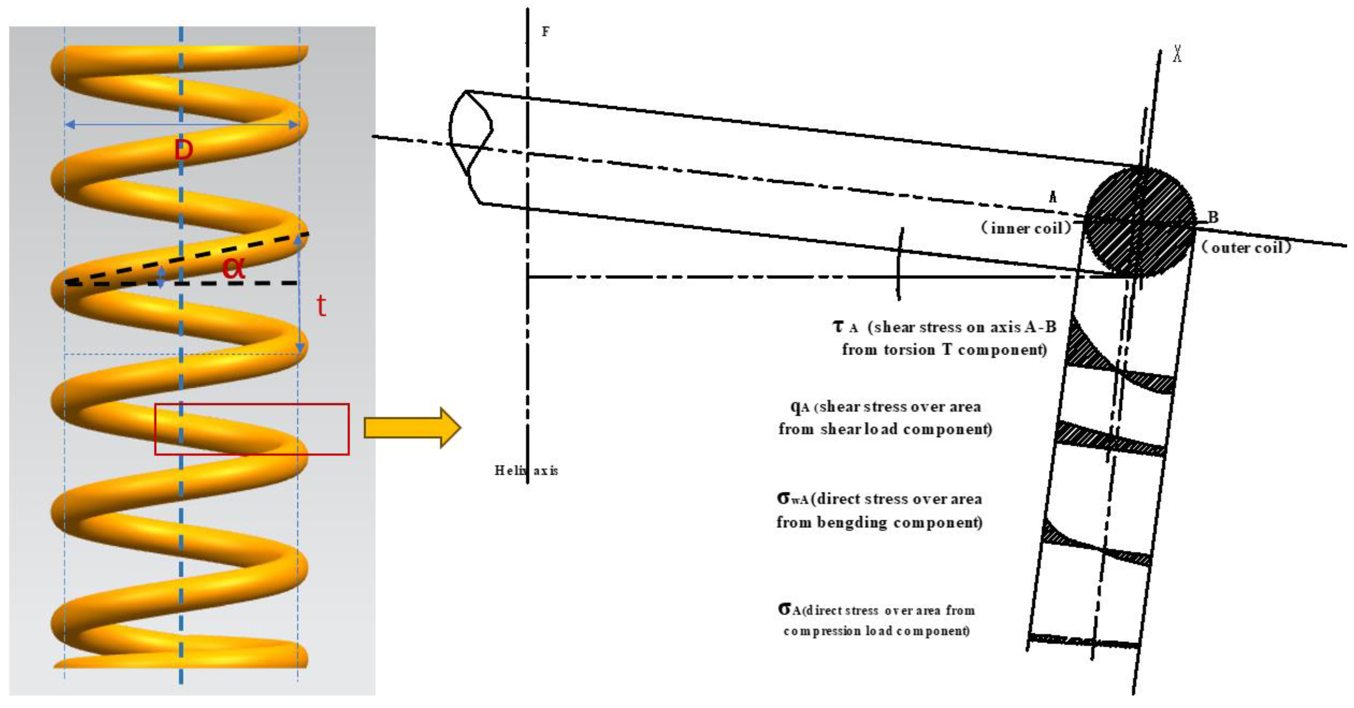
The geometric properties of a spring are determined by parameters such as wire diameter (d), mean coil diameter (D), helix angle (α), and pitch (t). Among these parameters, the spring index (C), which is the ratio of the wire diameter to the mean coil diameter, plays a crucial role in determining the curvature effect of the spring. It significantly affects the stress distribution and performance of the spring’s cross-section. Specifically, when the pitch ratio of a spring is less than seven, the curvature effect becomes significant, resulting in a notable increase in shear stress in the internal coils compared with the external coils. In addition, during cyclic loading, the periodic variation of the helix angle causes asynchronous changes in stress components across the spring’s cross-section, leading to a non-proportional multiaxial stress state.
Figure 1 shows the variation of four stress components along diameter A–B when subjected to axial loading F. The helix angle α is a variable parameter that changes with the applied load. The weakest point is inner coil point A, which is often prone to fatigue failure. Point A is in a two-dimensional stress state when subjected to axial loading, and the shear stress and normal stress components can be determined using the following calculations.
where F is the axial compressive force loaded to the spring, S is the area of the cross-section of the spring wire, α′ is the helix angle subjected to a load F, C is the spring index, and k is the spring index coefficient. These parameters can be expressed by
and
Because there is almost no deformation in the flattened support circle and because the stress and distribution of each effective circle are the same, the spring displacement is distributed equally to each effective circle after loading. Thus, the post-loading pitch value is calculated as follows:
where t is the spring pitch, F′ is the stiffness of the entire spring, and n is the active coils of the spring. The helix angle after loading is as follows:
The ratio of normal to shear stress will change periodically with load F, reflecting the asynchronous characteristics of the two stress components, according to the following:
where Q is a constant related to the curvature. It can be obtained from the following:
where n is the number of active coils. Therefore, the equivalent stress at inner coil point A for a spring subjected to axis loading F can be expressed as follows:
2.2. A Fatigue Life Prediction Model for Shot-Peened Springs without Considering Residual Stress Decay
When a spring is subjected to cyclic axial loads approximately ranging from F1 to F2, the surface residual compressive stress generated via shot peening significantly enhances the fatigue resistance of the spring. This beneficial effect of shot peening on extending the fatigue life is represented by residual stress and is introduced in the fatigue life prediction model in the form of average compressive stress. As described in reference [25], the maximum normal stress on the critical interface under the action of F1 can be expressed mathematically as follows:
where and are the normal and shear stresses, respectively, under the action of load F1, which can be calculated using Equations (1) and (2). is the residual compressive stress on the inner coil of the helical spring. Without considering the decay of residual stress, the initial residual stress of the shot-peened spring is introduced into the model as an average stress. Because the spring is always in a state of elastic deformation during service, the normal strain on the critical surface can be expressed as follows:
In addition, the fatigue damage parameter can be expressed as follows:
Thus, the relationship between fatigue life and fatigue damage of the steady-state residual stress life prediction model (SLP) model can be expressed as follows [26]:
where the fatigue strength exponent b, the fatigue ductility exponent c, the strength fatigue coefficient, and the fatigue ductility coefficient can be calculated from the mechanical properties of a material, according to the Muralidharan method [19]. The specific calculation method follows:
where is the fracture true stress, and is the fracture true strain. These can be calculated using the following formulas:
The four fatigue constants mentioned above are key parameters that determine the fatigue performance of the material. To achieve better predictive accuracy, we conducted torsional fatigue tests on the same batch of steel wire as the tested spring products and obtained the fitting data. The specific fitting data are listed in Table 1.
3. Experiments
3.1. Materials and Specimens
The specimen material used was 55CrSi, which is a widely used material in engineering, and its specific composition is presented in Table 2. The mechanical properties of the spring steel wire were measured, as shown in Table 3. The spring index is the ratio of the diameter of the reed wire to the middle diameter of the spring. It characterizes the curvature coefficient of the spring product. The smaller the spring index, the greater the spring curvature. To investigate the relationship between the residual stress relaxation behavior and the spring structure, in this work, we used spring indexes of 4, 5, 6, and 7 for comparison.
3.2. Shot Peening Treatment and Surface Condition Testing
3.2.1. Sample Preparation
We used springs with two different surface treatment states: non-shot-peened (NSP) and double-shot-peened (DSP). The shot-peened process parameters are listed in Table 4. By modifying certain parameters, such as the air pressure and muzzle distance, we could use an arc height measuring instrument to confirm the saturation curve of the Almen test piece until the set shot peening intensity was reached. The intensity of the secondary shot peening was much smaller than the first shot peening for the DSP sample. Table 5 describes the manufacturing process of the spring specimens in detail. All specimens underwent strong pressure treatments and twice-tempering, resulting in better dimensional and performance stability.
3.2.2. Surface Condition Measurement
Surface integrity has a significant impact on material fatigue life [27] and parameters that characterize surface integrity include surface roughness, hardness, residual stress, and full width at half maxima (FWHM) [28,29,30,31]. Therefore, surface condition testing incorporates the above four aspects. In this type of test, the working section of the fatigue specimen surface was marked with a marker, ensuring that the same area was measured each time. In this experiment, the fourth coil of the spring was marked as the comparison section.
The microhardness can directly reflect the work hardening process of a sample surface and can be used to characterize the degree of surface cold work and the depth of plastic deformation [32,33,34]. A future-tech FM-800 microhardness tester (FUTURE-TECH, Tokyo, Japan) was used to measure the hardness at several points along the depth direction of the inner coil. At every 30 μm, we created a test point along the depth direction of the hardened layer and then obtained measurements 1 and 2 mm from the surface (core).
Surface roughness produced via shot peening was caused by the stress concentrations of the surface notch effect, which can greatly influence fatigue resistance under cyclic loading [28,35,36,37]. In this experiment, we used a laser scanning confocal microscope to measure the surface roughness of the inner coil of the spring after shot peening.
To determine the residual stress relaxation behavior of the spring throughout the entire fatigue life under cyclic loading, we used a residual stress tester (PROTO, Vancouver, BC, Canada) based on X-ray diffraction (XRD) to measure the residual stresses under specific cycling times, along with the FWHM value. The fatigue machine can examine 128 samples of the fatigue test at the same time. It was stopped at a predetermined cycle point and a dual stress test was then performed. Then, other samples were used for the fatigue test. We measured the residual stresses at cycle periods of 1, 10, 100, 1000, 1.0 × 10⁴, and 1.0 × 10⁵. The relaxation of residual stresses was mainly concentrated in the first 10 cycles [16], and the dividing point between low-cycle and high-cycle fatigue was approximately 1.0 × 10⁴ [38]. The S–N curve slope from the high cycle to the infinite life fatigue limit was between 1.0 × 10⁵ and 1.0 × 10⁷ [5]. In the spring, the fatigue site during high-cycle fatigue is generally located in the direction of the maximum principal stress, which is located on the inner side of the coil, approximately 45° to the wire axis [5]. Thus, the residual stress measurement direction was 45° to the wire axis, using a lateral tilt fixed ψ method. The characteristic radiation for the chromium target was Kα, the diffraction crystal plane was αFe (211), and the scanning start and end angles were 151° and 163°, respectively. In addition, the stress constant K was −318 MPa/°. Owing to the small diameter (4 mm) of the steel wire spring specimens, the inner surface of the coil was difficult to detect. Therefore, the specimens were cut along the centerline using a wire cutter, and samples with different surface conditions were marked. A small magnet was used to hold the samples during testing to stabilize the required measurement angles. Because the X-rays had a limited ability to penetrate the specimens, they were only used to measure the residual stresses on the surface layer. Thus, electrolytic polishing was used to determine the residual stresses of the subsurface and deeper levels of the material. An XF-1 electrolytic polishing machine (POTECH, Ningbo, China) was used to strip the test pieces, and for every 30 μm thick layer, we performed electrolytic stripping, and the residual stresses of the 8 subsurface layers were measured between 30 to 210 μm.
3.3. Fatigue Performance Testing
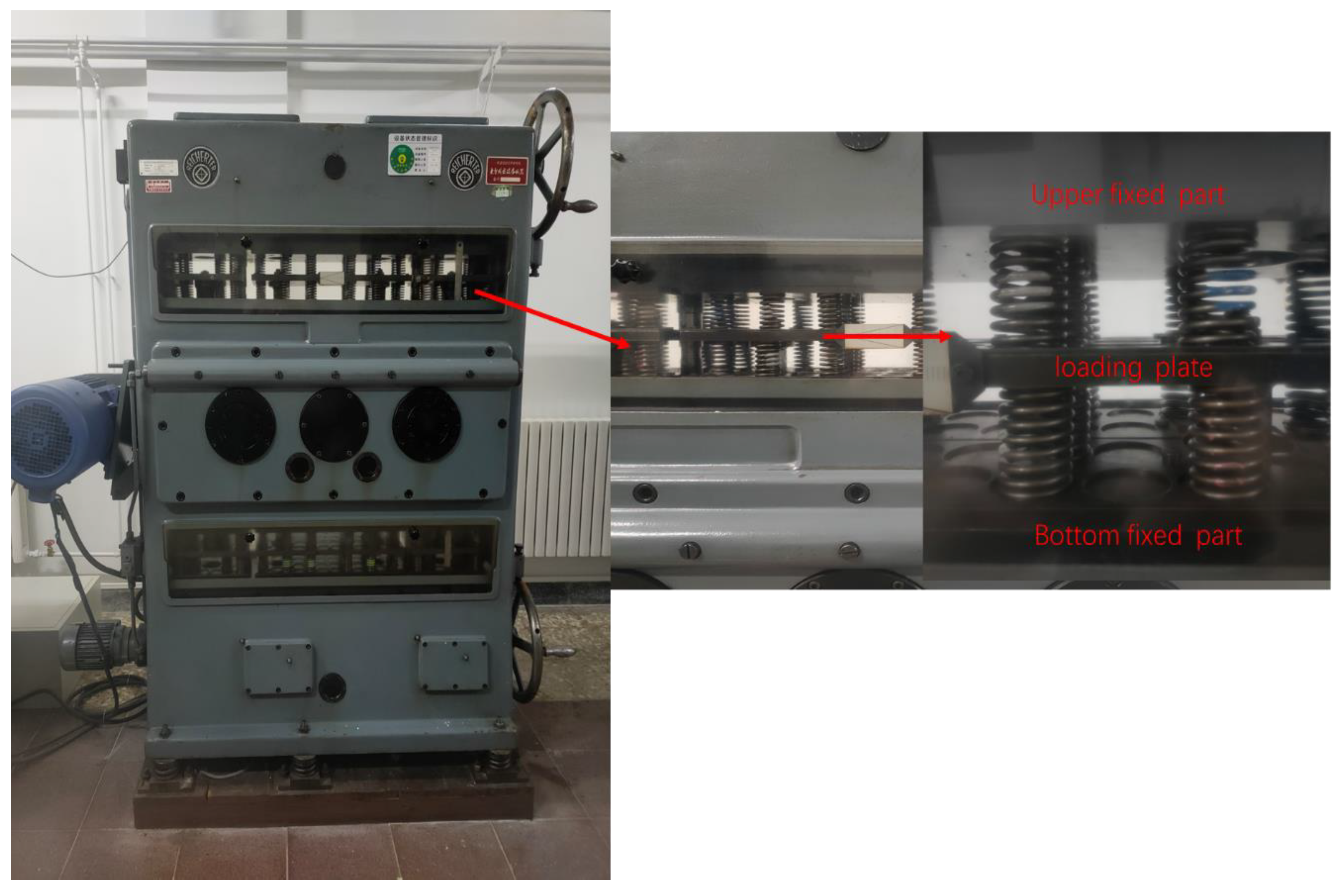
Spring fatigue tests were performed using a DV8 spring fatigue testing machine (REICHERTER, Munich, Germany) at room temperature, as Figure 2 shows, with several constant stress amplitudes and a nominal frequency of 20 Hz. The machine stroke was variable from near 0 to 28 mm. This setup was performed before the start of the test and remained constant during testing [5]. Before the start of the test, the upper and bottom fixing plates pre-compressed the upper and lower rows of springs, respectively, averaging and fixing the stress positions. During the test, the loading plate cyclically compressed the two rows of springs. The minimum and maximum stress positions of the upper and lower rows of springs were alternately cycled, and the springs were placed in a compressed state during the entire process.
To obtain a relationship between residual stress relaxation behavior and cyclic loading and the spring structure parameters, we set the cyclic tests with different cyclic coefficients and different stress levels for different spring index samples. When the specimen fatigue fractured or the number of cycles exceeded 1 × 10⁷, the fatigue test was terminated. The spring was not allowed to undergo plastic deformation. If plastic deformation occurred, the spring had failed and had no elastic function. In this study, the fatigue tests for all specimens followed high-cycle fatigue, and no plastic deformation occurred.
4. Results and Discussion
4.1. Shot-Peened Spring Surface Stress Relaxation Law
4.1.1. Residual Stress Relaxation Phenomenon
After undergoing shot peening treatment, the translated material experiences significant plastic deformation, resulting in the formation of a deformation layer. This process induces high levels of residual stress and generates many dislocations, leading to the accumulation of substantial strain energy within the deformation layer. Consequently, the material remains in an unstable state. The stored strain energy within the deformation layer is prone to release under conditions of high temperature or cyclic loading, causing the relaxation of residual stress and initiating microstructural changes.
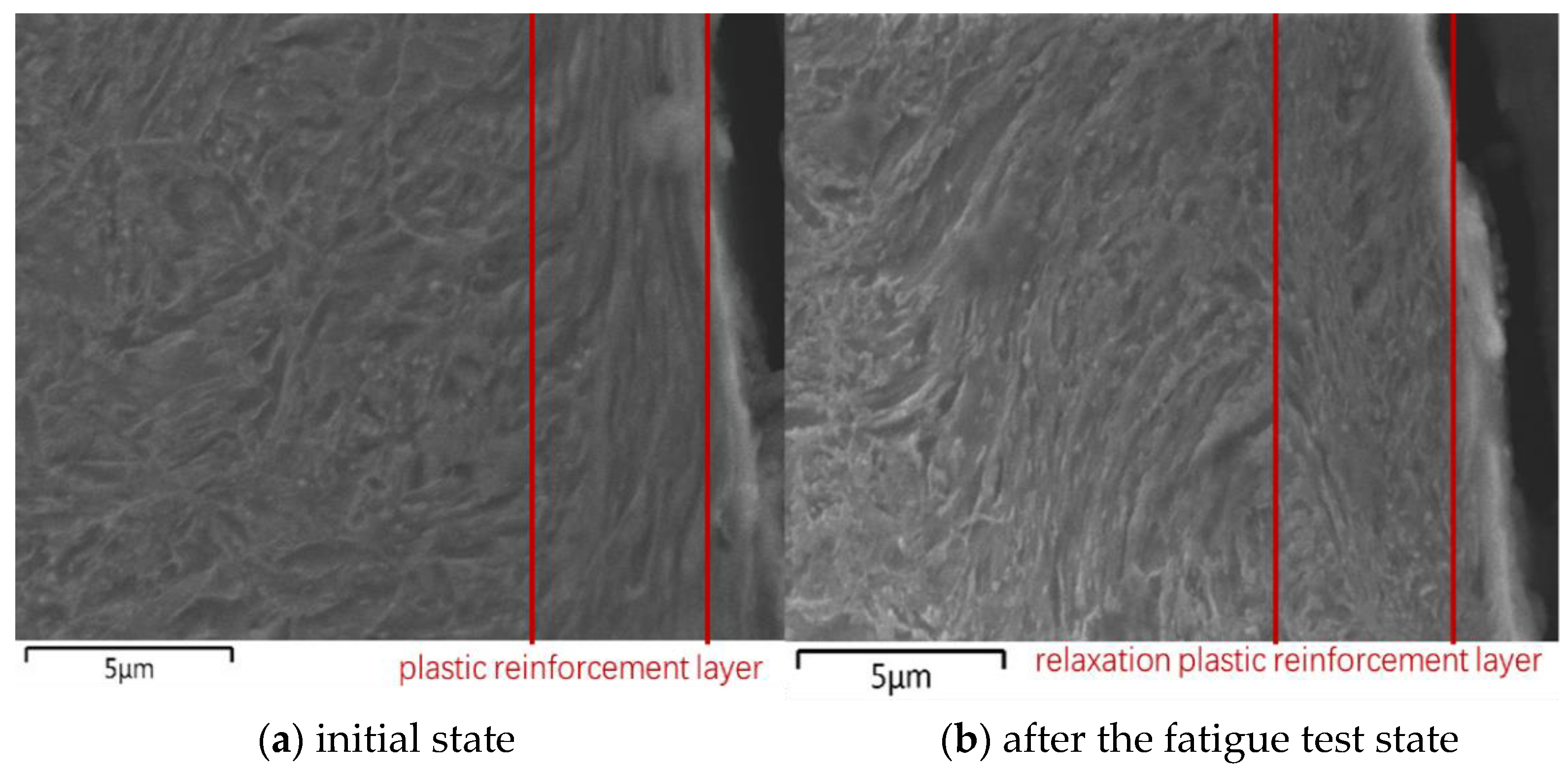
Upon conducting a comparative analysis of the microstructures of the DSP sample in its initial state and after fatigue testing, as shown in Figure 3, it became evident that a distinct plastic strengthening layer existed on the surface of the sample in its initial state. This layer played a crucial role in enhancing the fatigue life of the spring. However, in the sample subjected to fatigue testing, the plastic strengthening layer was less prominent, suggesting a certain degree of relaxation within this layer due to cyclic fatigue loading. This relaxation phenomenon may have implications for improving fatigue performance.
To investigate the key parameters that influence the relaxation of the spring, we conducted a study on the residual stress gradient on the surface of the samples under various loading conditions, cycle numbers, and spring parameters. Throughout these investigations, the shot peening conditions were kept constant.
4.1.2. Analysis of Factors Influencing the Decay of Residual Stress in Shot Peening Strengthening
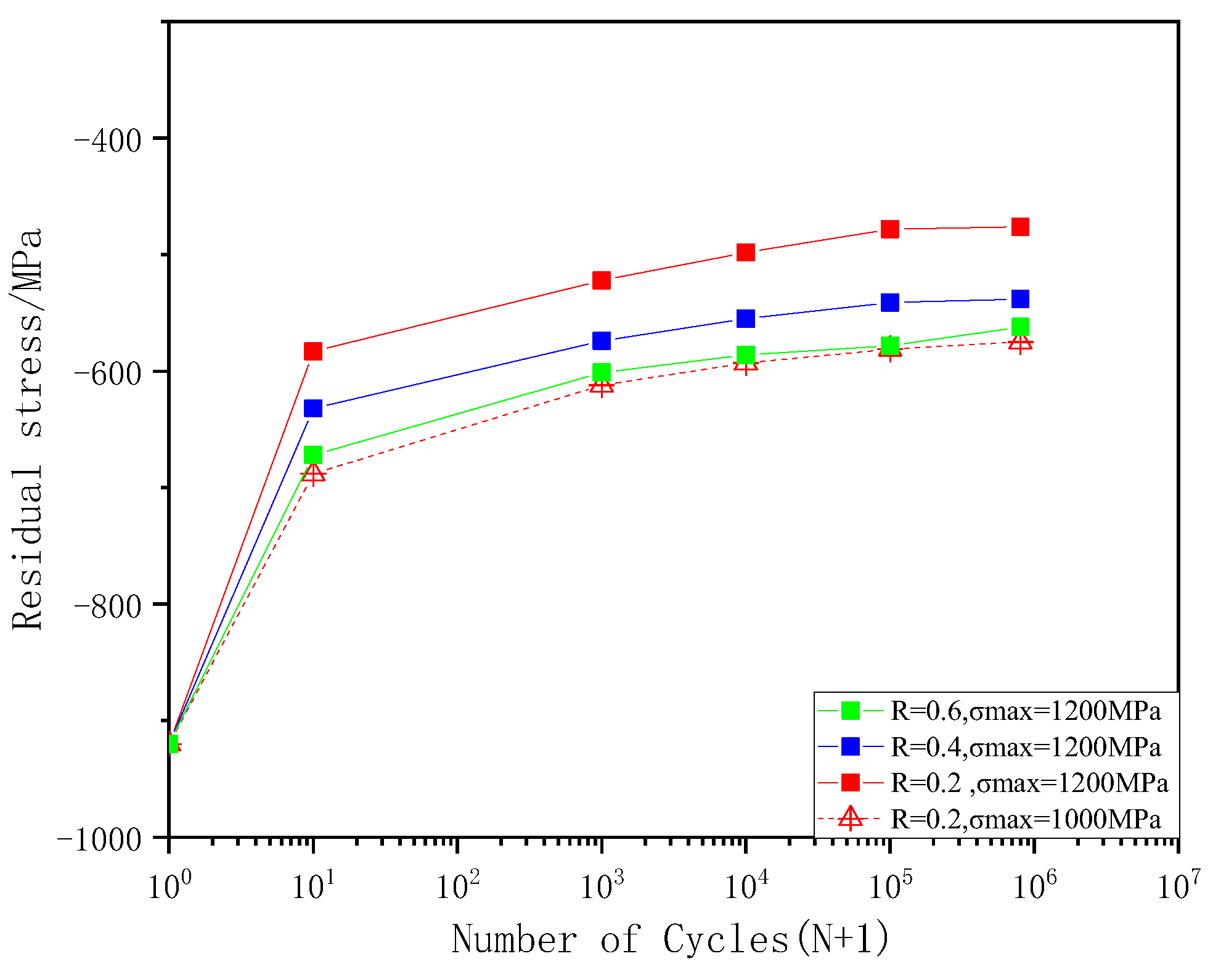
Figure 4 shows that the cycle coefficient remained constant, while the nominal stress dropped from 1200 to 1000 MPa, and the maximum compression residual stress increased from 522 to 688 MPa after 10 cycles. For other conditions, the cycle ratio increased from 0.2 to 0.6, and the maximum compression residual stress increased from −522 to −672 MPa after 10 cycles. As the cycle coefficient decreased, the stress amplitude increased, the fatigue damage parameter increased, and the residual stress field attenuation increased. Moreover, the residual stress attenuation law for different depth layers with the same number of cycles also differed. The residual stress within 90 μm of the surface layer and sub-surface layer attenuated sharply, whereas residual stresses within ~90–150 μm attenuated sharply during the first 10 cycles and then attenuated gradually. However, there was no sharp relaxation in residual stresses at depths of ~150–240 μm. Under a cyclic load of R = 0.2 and a nominal stress amplitude of 1200 MPa, the number of cycles increased from 10 to 1 × 10³ and 1 × 10⁵, and the hardened layer decreased by 20 and 35 μm, respectively. In addition, during the loading cycle, the hardened layer became shallow. Thus, the changing trend for the residual surface stress (within 90 μm) was the key factor that determined the effect of residual stress on extending lifespan. Furthermore, the maximum compressive residual stress along the depth direction of the shot-peened surface, which was subjected to fatigue cycling, was consistent with the law change. Therefore, attenuation was affected by the cycle coefficient, cyclic stress amplitude, and cycling times. As a result, in this study, we characterized the attenuation of residual stresses with the surface residual stress change law.
As shown in Figure 5, the residual stress relaxation values for the shot-peened samples were divided into two stages. The first stage consisted of a rapid decay in residual stresses (during the first 10 cycles), resulting in residual stress redistributions due to local plastic deformation with cycle loading in the stress-strengthening layer [39,40]. Thus, attenuation in this section accounted for approximately 40 to 60% of the attenuation throughout the entire life cycle. The second stage also consisted of a slow relaxation in residual stresses, and the evolution of mechanical properties caused by cyclic loading (cyclic softening or hardening of the affected layer) resulted in a release of residual stresses, which was similar to the logarithmic relationship of cycle time [17]. The decay rate of residual stresses under different cyclic conditions was significantly different despite the same initial residual stress. Thus, the cyclic coefficient and cyclic load were important factors that affected the decay rate. In fatigue with a high cycle count, as the number of cycles increases, even for the same specimen under different cycling conditions, the attenuation rate during the attenuation process will vary greatly. The residual stress will continue to be studied until fatigue failure of the specimen, and residual stress relaxation will transition from an unstable state to a stable state.
Figure 6 shows the significant differences in residual stress relaxation behavior between the different parts of the spring. After 10 cycles, the attenuation values of residual stresses on the inner coil, 1/4 circumference coil, and outer coil surfaces were 337, 288, and 248 MPa, respectively. The relaxation of the inner coil was significantly greater than the outer coil. The significant differences in residual stress attenuation reflected the differences in the stress cycle characteristics of the inner and outer coils. This also verified that the curvature effect of the spring was due to the helical structure, which affected the release of residual stresses. As the number of cycles increased, the gap between the attenuation of the inner and outer coil shrank. Residual stress values of the inner and outer coils were steady before fatigue fracture, and both reached a steady state. Figure 7 shows that the structural parameters of the spring were important factors that affected the residual stress relaxation behavior. When the spring index dropped from seven to four after 10 cycles, residual stress relaxation increased by 31% (from 257 to 337 MPa). As the spring index increased, the attenuation of residual stresses slowed down.
4.1.3. Residual Stress Relaxation Behavior Based on Spring Structure Characteristics
The fatigue lifespan extension effect produced via shot peening can be characterized by residual compressive stresses. It can also be related to the cycle coefficient, stress amplitude, surface roughness of the test piece, and structural parameters, where the attenuation changes with an increasing number of cycles. M. Benedetti et al. [25] proposed the use of stable residual stress as the average stress to introduce the high-cycle multiaxial fatigue criterion into Crossland and Findley. This approach was used to predict the high-cycle fatigue life of aluminum alloy sheets, and the prediction error did not exceed 15% through experimentation. Although its relaxation rate dropped significantly after 100 cycles, the relaxation effect of residual stresses accumulated after high cycling could not be ignored, according to the residual stress relaxation behavior under cyclic loading [41]. The residual stresses introduced in the form of a constant to create the multiaxis prediction model may have caused a large error in the prediction results. This could be especially pronounced for the smaller spring index (significant curvature effect), the higher mean stress, and the higher cyclic stress amplitude parameters. Therefore, in this work, we proposed a residual stress influencing factor to characterize the inhibitory effect of this attenuation on fatigue life.
Periodic mechanical loads will reduce residual compressive stresses after shot peening. Shun Yang et al. [12] summarized models that characterized the evolution of residual stress relaxation: the logarithmic criterion (LC) and the power criterion (PC).
The LC model describes the linear relationship between the attenuation of residual stresses and the logarithm of the number of cycles. This relationship is relatively simple and has been widely used to describe the evolution characteristics of residual stresses as a result of shot peening [42]. This expression is expressed via the following:
where is the cycle time of the thermal field, and is the residual stress on the inner coil after N cycles. A1 and m1 are the fitting constants. The residual stress decay process can also be divided into two stages: rapid release and steady-state release [16]. However, the LC model cannot characterize the residual stress rapid release phase.
The PC model considers the cyclic coefficient, cyclic stress amplitude, and the attenuation of residual stresses according to the number of cycles, which is more appropriate to describe residual stress relaxation behavior. It can be written as follows:
where A′ is the material constant determined by the material stress-strain relationship, and m is the fitting constant determined by the material properties and cyclic loading conditions. The fitting constant B controls the degree of influence for the number of cycles. Shun Yang et al. [12] used a model to accurately predict the attenuation of residual stresses during a uniaxial tensile fatigue test of a shot-peened test bar when the cycle coefficient was −1. The helical structure of a spring causes it to experience a non-proportional stress state under cyclic axial loading. Figure 5 shows a significant difference in the attenuation of residual stress between the inner and outer coils of the spring, and Figure 6 demonstrates that springs with different spring indexes exhibit varying degrees of residual stress attenuation under identical cyclic loading conditions. However, the PC model fails to account for the influence of structural parameters and cannot determine the variations in residual stress attenuation among springs with different spring index values, especially under identical cyclic loading and initial residual stress conditions. For this, a residual stress attenuation factor based on a spring structure was proposed.
Residual stress attenuation of the spring is unique because of the curvature coefficient and the cyclically changing helical angle, which are the two structural characteristics of springs. The periodically changing helical angle under cyclic loading causes the non-proportional factor of the stress component to increase. Thus, non-proportional loading has a strong effect on the dislocation substructure of the material. As a result, the angle of the critical plane will increase, leading to more slip systems and increased residual stress relaxation [43]. Therefore, the change in the critical surface angle during the cyclic period will affect the non-proportional factor under alternating cyclic loading (F1–F2). This can be expressed as follows:
Although the non-proportional effect is more significant in low-cycle fatigue where macroscopic plastic deformation occurs, the non-proportional effect of high-cycle fatigue should also be considered. As the stress levels increase, the non-proportional effect of maximum stress will be closer to the yield limit, and more microplastic deformation will accumulate, resulting in a more noticeable non-proportional effect [44]. Therefore, the ratio of maximum equivalent stress to the yield limit is also a component of the non-proportional factor. This can be expressed as follows:
For proportional loading, there are no critical surface changes while the non-proportional factor is one, which does not affect the attenuation process of residual stresses. Therefore, the curvature effect as a result of the spring index will affect the attenuation of the residual stress. As shown in Figure 7, the residual stress of the inner coil that was released was significantly larger than that of the outer coil. The curvature coefficient proposed by Whale was introduced into the residual stress relaxation model [6] as follows:
where K is the curvature coefficient. This is expressed as follows:
The above formula reflects that as the spring index C decreases (the smaller diameter is not negligible relative to the larger diameter), this leads to an increased curvature coefficient K, resulting in a more significant spring curvature effect. As a result, this causes more severe residual stress relaxation behavior. The expression for the residual stress attenuation factor is as follows:
Shot peening of elastoplastic metal materials introduces multiple micronotches on the shot-peened surface, which cause stress concentration under mechanical load. The stress concentration factor caused via shot peening can be expressed as follows [45,46]:
where Rt and Dp indicate the mean-to-peak valley heights and the spacing of the adjacent peaks in the roughness profile within an evaluation length of 2 mm, respectively.
The surface roughness of shot-peened springs increases the stress concentration factor, affecting the decay pattern of residual stresses. By incorporating the surface roughness Formula (28), the decay pattern of residual stresses based on the structural characteristics of the spring can be represented as follows:
Compared with the PC model, which describes the relaxation of residual stresses under cyclic uniaxial stress, the improved model can describe the attenuation of residual stresses under cyclic multiaxial non-proportional stress. The curvature effect becomes more significant as the spring index decreases, resulting in more severe attenuation of residual stresses under the same conditions. This behavior was more consistent with the actual release of residual stresses in springs. Figure 8 shows the comparison between the predicted residual stress release values of the two models and the experimental attenuation values. The PC model cannot capture the influence of different spring indexes on the attenuation of residual stresses. When the spring index showed C = 7, both methods showed similar prediction errors and achieved good predictive performance. However, when C = 4, the improved model predicted values that were significantly closer to the measured values.
4.2. Prediction and Validation of the Fatigue Life for Shot-Peened Springs
4.2.1. Characterization Method for the Dynamic Attenuation of Residual Stress and Its Effect on Extending Fatigue Life
The life extension benefit, as a result of residual stress, remains throughout the entire cycle, whereas residual stresses continues to attenuate during cyclic loading. Spring fatigue life, which can be predicted based on static residual stress, considerably exceeds the actual life of the spring. Therefore, this parameter was not conducive to lifespan assessment. As a result, we proposed a life prediction model based on the dynamic attenuation of residual stresses. The integral of residual stress on cycling can be used to characterize the effects of decayed residual stress. Thus, the residual stresses that corresponded to each cycle acted once, and the overall effect was a compilation of residual stresses. Because residual stress decreases slowly after 1000 cycles, the residual stress values for the two adjacent cycles barely changes. Residual stress can be calculated as follows:
is the residual stress according to N cycles. The effect of residual stress during the Nth cycle can be expressed by the differences between the residual stresses that act during n times and the residual stresses that act n−1 times. Therefore, according to Equation (16), we can replace as part of the as follows:
Thus, the cumulative effect of residual stresses during 1000 N cycles H can be expressed as follows:
and after offsetting the same items as follows:
Therefore, the residual stress effect during the first 1000 cycles can be expressed as follows:
The equivalent attenuation factor of the residual stress can be expressed by the ratio of the attenuated residual stress effect under a cycle period N with the steady-state initial residual stress effect under N cycles. This can be expressed as follows:
4.2.2. Prediction Model and Validation of Spring Life Based on Residual Stress Decay
The determination of the life gain caused by residual stresses depends on the accumulation of the residual stress variation throughout the entire cycle. The impact of residual stresses induced via shot peening on life extension can be incorporated into the prediction model by multiplying the equivalent attenuation factor with the initial residual stress for a specific cycle. Furthermore, the improved life prediction model also considers the inhibitory effect of increased surface roughness caused via shot peening on life extension. The stress concentration resulting from roughness was manifested in two aspects. The first factor was the intensification of cyclic loading, while the second factor accelerated the release of residual stresses. Therefore, the spring life prediction model based on the decay pattern of residual DLP stresses and the stress concentration effect induced via shot peening and the dynamic residual stress life prediction model can be expressed as follows:
Spring fatigue data exhibit characteristics of data dispersion and stress sensitivity. Table 6 presents the mean fatigue life and standard deviation of samples with different conditions and specifications under specific cyclic loading conditions.
C = 4 specification spring samples were selected with a stress ratio set to 0.2. The fatigue life distributions of NSP and DSP specimens were compared at different stress levels, as depicted in Figure 9. The DSP specimens exhibited significantly enhanced average lifespans compared with the NSP specimens, especially at lower stress levels (σ = 1000 MPa), where the life increased by as much as 12.36 times, indicating a more pronounced life extension effect. In addition, shot peening significantly reduced the dispersion of the fatigue life distribution of the springs. Even in the low-stress region with a relatively dispersed life distribution (σ = 1000 MPa), the standard deviation was small (0.14939), effectively ensuring the high reliability of the product in service.
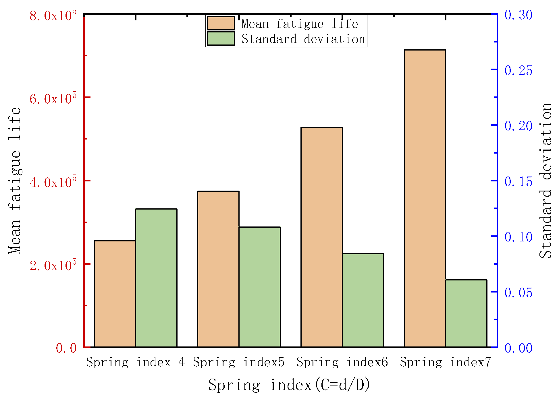
Figure 10 shows the mean fatigue life and scatter of fatigue data for springs with different spring indexes under stress conditions r = 0.2 and σ = 1200 MPa. The mean fatigue life of the springs tends to increase with a higher spring index. Under the same stress condition, the mean life of the spring with spring index C = 7 was 2.86 times that of the spring with spring index C = 4. Increasing the spring index also affected the scatter of fatigue life in shot-peened springs. Under the same conditions, the standard deviations for springs with spring indexes four, five, six, and seven were 0.1243, 0.10815, 0.08406, and 0.0606, respectively. A higher spring index reduced the scatter of fatigue data by more than half. The spring index represents the curvature effect of the spring. A smaller spring index results in more significant curvature effects, leading to a more intense release of residual stress and weakening the life extension effect of residual stress.
An error band test chart is plotted twice in Figure 11 to compare the predictions of two life prediction methods (SLP and DLP) with the experimental values. The SLP method consistently predicted longer life spans than the actual measured life spans (above the Iso lifeline). As the stress level increased, the release of residual stress intensified, leading to a weakening of the life extension effect. The SLP method, which neglected the dynamic decay of residual stress during cycles, resulted in more aggressive predictions due to the assumption of a stable life extension effect caused by residual stress. At a stress level of 1200 MPa, the predicted life spans mostly exceeded the two-time error life band. The DLP life prediction method demonstrated better accuracy. It remained within the two-time error band range for stress levels from 1000 to 1200 MPa. The data points were mainly below the Iso lifeline, particularly in the high-stress region (1000 MPa).
5. Conclusions
An experimental study was conducted to investigate the effects of shot peening on residual stress attenuation and fatigue behavior in springs with varying spring indexes. The study aimed to understand the relationship between residual stress attenuation and spring structural characteristics. The dynamic relaxation of residual stress during service cycles was quantified and integrated into a shot-peened spring life prediction model, leading to the following conclusions:
- Shot peening is an effective method for enhancing the fatigue performance of springs. It significantly reduces the variability in spring fatigue life, thus improving the reliability of spring operation.
- Under cyclic loading, shot-peened springs experience stress relaxation, with the most significant relaxation occurring at the inner coil of the spring. This relaxation is influenced not only by the number of cycles, maximum stress, and stress amplitude but also by the spring index of the spring. Smaller spring indexes (indicating a more pronounced curvature effect) result in more severe residual stress attenuation in the spring under the same conditions.
- Observations indicated that the residual stress values of two adjacent cycles became nearly equal once the steady-state relaxation stage was reached. A quantified model capturing the dynamic relaxation of residual stress during the entire cycle accurately described the life extension effect induced via shot peening.
- Residual stress relaxation was the primary limiting factor for improving the fatigue response via shot peening. When predicting the fatigue strength of springs using multiaxial fatigue criteria, it is crucial to consider the dynamic variation of residual stress rather than relying on the initial residual stress as the steady-state value.
Author Contributions
Conceptualization, C.S. and P.C.; methodology, C.S.; software, C.S.; validation, C.S., D.W. and Y.Z.; formal analysis, C.S.; investigation, C.S.; resources, D.W.; data curation, P.C.; writing—original draft preparation, C.S.; writing—review and editing, D.W.; supervision, Y.Z. All authors have read and agreed to the published version of the manuscript.
Funding
The authors thank the China Productivity Center for Machinery and the China Academy of Machinery Science and Technology Group Co., Ltd., for their financial support. This paper was supported by the project “National Key Research and Development Program of China—Research Project on Universal International Standards for Equipment Manufacturing Fundamentals” (2021YFF0601702).
Data Availability Statement
The data presented in this study are available on request from the corresponding author. The data are not publicly available due to project execution requirements.
Conflicts of Interest
Authors Chenxi Shao and Peng Cheng were employed by the company Yanqi Lake (Beijing) Institute of Basic Manufacturing Technology Research Co., Ltd. Author Decheng Wang was employed by the company China Academy of Machinery Science and Technology Group Co., Ltd. The remaining authors declare that the research was conducted in the absence of any commercial or financial relationships that could be construed as a potential conflict of interest. The authors declare that this study received funding from China Productivity Center for Machinery and the China Academy of Machinery Science and Technology Group Co., Ltd. The funder had the following involvement with the study: Residual Stress Testing and Spring Fatigue Testing.
Nomenclature
| d | wire diameter | initial residual stress on the inner coil | |
| D | mean coil diameter | residual stress on the inner coil after N cycles | |
| n | active coils | fitting constant for the PC model | |
| α | helix angle | Boltzmann constant | |
| t | spring pitch | cycle time of the thermal field | |
| helix angle after loading | exponential constant for the PC model | ||
| post-loading pitch | activation enthalpy of the relaxation process | ||
| C | spring index | relaxation temperature | |
| K | spring index coefficient | fitting constant for the LC model | |
| F′ | stiffness of the entire spring | fitting constant for the LC model | |
| S | area for the cross-section of the spring wire | material constant for the PC model | |
| F | axial compressive force | m | fitting exponential constant for the PC model |
| ratio of normal to shear stress | B | fitting constant controls the degree of influence for the number of cycles | |
| Q | constant related to the curvature | residual stress attenuation factor | |
| equivalent stress at the inner coil | the angle of the critical plane under F1 | ||
| normal stress under load F1 | angle amplitude of the critical plane | ||
| shear stress under load F1 | mean to peak valley heights of the roughness profile | ||
| maximum normal stress on the critical interface under F1 | Dp | spacing of the adjacent peaks in the roughness profile | |
| cyclic stress amplitude | stress concentration factor | ||
| yield strength | K | curvature coefficient | |
| residual stress on the inner coil | H | cumulative effect of residual stresses during 1000~N cycles | |
| critical interface normal strain amplitude | residual stress effect during the first 1000 cycles | ||
| fatigue damage parameter | equivalent attenuation factor for residual stress | ||
| b | fatigue strength exponent | Subscripts | |
| c | fatigue ductility exponent | XRD | X-ray diffraction |
| strength fatigue coefficient | SWT | Smith–Watson–Topper model | |
| fatigue ductility coefficient | DSP | double sheet peened | |
| fracture true stress | LC | logarithmic criterion | |
| fracture true strain | PC | power criterion | |
| Φ | reduction rate of the cross-sectional area | DLP | dynamic residual stress life prediction model |
| SLP | steady-state residual stress life prediction model |
References
- Fakhreddine, D.; Mohamed, T.; Said, A.; Abderrazek, D.; Mohamed, H. Finite element method for the stress analysis of isotropic cylindrical helical spring. Eur. J. Mech.-A Solids 2005, 24, 1068–1078. [Google Scholar] [CrossRef]
- Chiu, C.-H.; Hwan, C.-L.; Tsai, H.-S.; Lee, W.-P. An experimental investigation into the mechanical behaviors of helical composite springs. Compos. Struct. 2007, 77, 331–340. [Google Scholar] [CrossRef]
- Hashemi, Y.M.; Kadkhodaei, M.; Mohammadzadeh, M.R. Fatigue analysis of shape memory alloy helical springs. Int. J. Mech. Sci. 2019, 161, 105059. [Google Scholar] [CrossRef]
- Pyttel, B.; Brunner, I.; Kaiser, B.; Berger, C.; Mahendran, M. Fatigue behavior of helical compression springs at a very high number of cycles—Investigation of various influences. Int. J. Fatigue 2014, 60, 101–109. [Google Scholar] [CrossRef]
- Kaiser, B.; Pyttel, B.; Berger, C. VHCF-behavior of helical compression springs made of different materials. Int. J. Fatigue 2011, 33, 23–32. [Google Scholar] [CrossRef]
- Berger, C.; Kaiser, B. Results of very high cycle fatigue tests on helical compression springs. Int. J. Fatigue 2006, 28, 1658–1663. [Google Scholar] [CrossRef]
- Nie, B.; Zhang, Z.; Zhao, Z.; Zhong, Q. Very high cycle fatigue behavior of shot-peened 3Cr13 high strength spring steel. Mater. Des. 2013, 50, 503–508. [Google Scholar] [CrossRef]
- Aggarwal, M.; Agrawal, V.; Khan, R. A stress approach model for predictions of fatigue life by shot peening of EN45A spring steel. Int. J. Fatigue 2006, 28, 1845–1853. [Google Scholar] [CrossRef]
- Seddik, R.; Ben Sghaier, R.; Atig, A.; Fathallah, R. Fatigue reliability prediction of metallic shot peened-parts based on Wöhler curve. J. Constr. Steel Res. 2017, 130, 222–233. [Google Scholar] [CrossRef]
- Arakawa, J.; Hanaki, T.; Hayashi, Y.; Akebono, H.; Sugeta, A. Evaluating the fatigue limit of metals having surface compressive residual stress and exhibiting shakedown. Fatigue Fract. Eng. Mater. Struct. 2019, 43, 211–220. [Google Scholar] [CrossRef]
- Wu, J.; Liu, H.; Wei, P.; Lin, Q.; Zhou, S. Effect of shot peening coverage on residual stress and surface roughness of 18CrNiMo7-6 steel. Int. J. Mech. Sci. 2020, 183, 105785. [Google Scholar] [CrossRef]
- Yang, S.; Zeng, W.; Yang, J. Characterization of shot peening properties and modelling on the fatigue performance of 304 austenitic stainless steel. Int. J. Fatigue 2020, 137, 105621. [Google Scholar] [CrossRef]
- Walker, J.; Thomas, D.J.; Gao, Y. Effects of shot peening and pre-strain on the fatigue life of dual phase Martensitic and Bainitic steels. J. Manuf. Process. 2017, 26, 419–424. [Google Scholar] [CrossRef]
- Barry, N.; Hainsworth, S.; Fitzpatrick, M. Effect of shot peening on the fatigue behaviour of cast magnesium A8. Mater. Sci. Eng. A 2009, 507, 50–57. [Google Scholar] [CrossRef]
- Avilés, R.; Albizuri, J.; Ukar, E.; Lamikiz, A.; Avilés, A. Influence of laser polishing in an inert atmosphere on the high cycle fatigue strength of AISI 1045 steel. Int. J. Fatigue 2014, 68, 67–79. [Google Scholar] [CrossRef]
- Kim, J.-C.; Cheong, S.-K.; Noguchi, H. Residual stress relaxation and low- and high-cycle fatigue behavior of shot-peened medium-carbon steel. Int. J. Fatigue 2013, 56, 114–122. [Google Scholar] [CrossRef]
- Chen, M.; Xing, S.; Liu, H.; Jiang, C.; Zhan, K.; Ji, V. Determination of surface mechanical property and residual stress stability for shot-peened SAF2507 duplex stainless steel by in situ X-ray diffraction stress analysis. J. Mater. Res. Technol. 2020, 9, 7644–7654. [Google Scholar] [CrossRef]
- Lin, T.; Zhang, Q.; Lian, Z.; Liu, Y.; Zhang, Y.; Chen, Y. Multi-axial fatigue life prediction of drill collar thread in gas drilling. Eng. Fail. Anal. 2016, 59, 151–160. [Google Scholar] [CrossRef]
- Del Llano-Vizcaya, L.; Rubio-González, C.; Mesmacque, G.; Cervantes-Hernández, T. Multiaxial fatigue and failure analysis of helical compression springs. Eng. Fail. Anal. 2006, 13, 1303–1313. [Google Scholar] [CrossRef]
- Rubiella, C.; Hessabi, C.A.; Fallah, A.S. State of the art in fatigue modelling of composite wind turbine blades. Int. J. Fatigue 2018, 117, 230–245. [Google Scholar] [CrossRef]
- Xu, S.; Zhu, S.-P.; Hao, Y.-Z.; Liao, D.; Qian, G. A new critical plane-energy model for multiaxial fatigue life prediction of turbine disc alloys. Eng. Fail. Anal. 2018, 93, 55–63. [Google Scholar] [CrossRef]
- Augustins, L. An empirical multiaxial high cycle fatigue criterion for automotive cylinder head design. Eng. Fail. Anal. 2013, 28, 264–274. [Google Scholar] [CrossRef]
- Sepe, R.; Greco, A.; De Luca, A.; Armentani, E.; Berto, F. Experimental and FEM numerical assessment of multiaxial fatigue failure criteria for a rolling Stock’s seats structure. Eng. Fail. Anal. 2019, 102, 303–317. [Google Scholar] [CrossRef]
- Huang, L.; Shi, Y.; Guo, H.; Su, X. Fatigue behavior and life prediction of self-piercing riveted joint. Int. J. Fatigue 2016, 88, 96–110. [Google Scholar] [CrossRef]
- Benedetti, M.; Fontanari, V.; Bandini, M.; Taylor, D. Multiaxial fatigue resistance of shot peened high-strength aluminum alloys. Int. J. Fatigue 2014, 61, 271–282. [Google Scholar] [CrossRef]
- Kujawski, D. A deviatoric version of the SWT parameter. Int. J. Fatigue 2014, 67, 95–102. [Google Scholar] [CrossRef]
- Takahashi, K.; Kogishi, Y.; Shibuya, N.; Kumeno, F. Effects of laser peening on the fatigue strength and defect tolerance of aluminum alloy. Fatigue Fract. Eng. Mater. Struct. 2020, 43, 845–856. [Google Scholar] [CrossRef]
- Rotella, G. Effect of surface integrity induced by machining on high cycle fatigue life of 7075-T6 aluminum alloy. J. Manuf. Process. 2019, 41, 83–91. [Google Scholar] [CrossRef]
- Jouini, N.; Revel, P.; Thoquenne, G. Influence of surface integrity on fatigue life of bearing rings finished by precision hard turning and grinding. J. Manuf. Process. 2020, 57, 444–451. [Google Scholar] [CrossRef]
- Zhang, S.; Yang, Z.; Jiang, R.; Jin, Q.; Zhang, Q.; Wang, W. Effect of creep feed grinding on surface integrity and fatigue life of Ni3Al based superalloy IC10. Chin. J. Aeronaut. 2020, 34, 438–448. [Google Scholar] [CrossRef]
- Javidi, A.; Rieger, U.; Eichlseder, W. The effect of machining on the surface integrity and fatigue life. Int. J. Fatigue 2008, 30, 2050–2055. [Google Scholar] [CrossRef]
- Franc, J.; Moravec, P.; Dědič, V.; Roy, U.; Elhadidy, H.; Minárik, P.; Šíma, V. Microhardness study of Cd1-x ZnxTe1-ySey crystals for X-ray and gamma ray detectors. Mater. Today Commun. 2020, 24, 101014. [Google Scholar] [CrossRef]
- Lasota, I.; Protsenko, V.; Matyushkin, A.; Kuznetsov, M.; Gook, S. Laser surface hardening of engine camshaft cams. Mater. Today Proc. 2020, 30, 478–482. [Google Scholar] [CrossRef]
- Chen, C.; Zeng, X.; Wang, Q.; Lian, G.; Huang, X.; Wang, Y. Statistical modelling and optimization of microhardness transition through depth of laser surface hardened AISI 1045 carbon steel. Opt. Laser Technol. 2020, 124, 105976. [Google Scholar] [CrossRef]
- Vayssette, B.; Saintier, N.; Brugger, C.; El May, M. Surface roughness effect of SLM and EBM Ti-6Al-4V on multiaxial high cycle fatigue. Theor. Appl. Fract. Mech. 2020, 108, 102581. [Google Scholar] [CrossRef]
- Lee, S.; Pegues, J.W.; Shamsaei, N. Fatigue behavior and modeling for additive manufactured 304L stainless steel: The effect of surface roughness. Int. J. Fatigue 2020, 141, 105856. [Google Scholar] [CrossRef]
- Fu, P.; Chu, R.; Xu, Z.; Ding, G.; Jiang, C. Relation of hardness with FWHM and residual stress of GCr15 steel after shot peening. Appl. Surf. Sci. 2018, 431, 165–169. [Google Scholar] [CrossRef]
- Fathallah, R.; Laamouri, A.; Sidhom, H.; Braham, C. High cycle fatigue behavior prediction of shot-peened parts. Int. J. Fatigue 2004, 26, 1053–1067. [Google Scholar] [CrossRef]
- Martín, V.; Vázquez, J.; Navarro, C.; Domínguez, J. Effect of shot peening residual stresses and surface roughness on fretting fatigue strength of Al 7075-T651. Tribol. Int. 2020, 142, 106004. [Google Scholar] [CrossRef]
- Wang, X.; Meng, Q.; Hu, W. Fatigue life prediction for butt-welded joints considering weld-induced residual stresses and initial damage, relaxation of residual stress, and elasto-plastic fatigue damage. Fatigue Fract. Eng. Mater. Struct. 2019, 42, 1373–1386. [Google Scholar] [CrossRef]
- Okorokov, V.; MacKenzie, D.; Gorash, Y.; Morgantini, M.; van Rijswick, R.; Comlekci, T. High cycle fatigue analysis in the presence of autofrettage compressive residual stress. Fatigue Fract. Eng. Mater. Struct. 2018, 41, 2305–2320. [Google Scholar] [CrossRef]
- Xie, L.; Wen, Y.; Zhan, K.; Wang, L.; Jiang, C.; Ji, V. Characterization on surface mechanical properties of Ti–6Al–4V after shot peening. J. Alloys Compd. 2016, 666, 65–70. [Google Scholar] [CrossRef]
- Malek, B.; Mabru, C.; Chaussumier, M. Fatigue behavior of 2618-T851 aluminum alloy under uniaxial and multiaxial loadings. Int. J. Fatigue 2020, 131, 105322. [Google Scholar] [CrossRef]
- Liu, T.; Shi, X.; Zhang, J.; Fei, B. Multiaxial high-cycle fatigue failure of 30CrMnSiA steel with mean tension stress and mean shear stress. Int. J. Fatigue 2019, 129, 105219. [Google Scholar] [CrossRef]
- Rodopoulos, C. Optimisation of the fatigue resistance of 2024-T351 aluminium alloys by controlled shot peening—Methodology, results, and analysis. Int. J. Fatigue 2004, 26, 849–856. [Google Scholar] [CrossRef]
- Bag, A.; Delbergue, D.; Ajaja, J.; Bocher, P.; Lévesque, M.; Brochu, M. Effect of different shot peening conditions on the fatigue life of 300 M steel submitted to high stress amplitudes. Int. J. Fatigue 2019, 130, 105274. [Google Scholar] [CrossRef]
Figure 1.
Analysis of spring structural characteristics and cross-sectional stress.

Figure 2.
Spring fatigue machine, indicating the loading and fixed sections.

Figure 3.
DSP microstructure of the sample surface in the initial state and after fatigue testing (d = 4.0 mm, C = 7).
Figure 3.
DSP microstructure of the sample surface in the initial state and after fatigue testing (d = 4.0 mm, C = 7).

Figure 4.
DSP sample under different cyclic loading ratios, nominal stress amplitudes, cycle times (d = 4.0 mm, C = 7, DSP, inner coil), and distribution of residual stress along the depth direction.
Figure 4.
DSP sample under different cyclic loading ratios, nominal stress amplitudes, cycle times (d = 4.0 mm, C = 7, DSP, inner coil), and distribution of residual stress along the depth direction.

Figure 5.
Relaxation law of maximum residual stress on the surface of the inner coil under different cycle conditions (d = 4.0 mm, C = 4, DSP, inner coil).
Figure 5.
Relaxation law of maximum residual stress on the surface of the inner coil under different cycle conditions (d = 4.0 mm, C = 4, DSP, inner coil).

Figure 6.
Attenuation law for residual stress on the spring surface at different positions along the circumferential direction (d = 4.0 mm, C = 4, DSP, r = 0.2, 1200 MPa).
Figure 6.
Attenuation law for residual stress on the spring surface at different positions along the circumferential direction (d = 4.0 mm, C = 4, DSP, r = 0.2, 1200 MPa).

Figure 7.
Residual stress attenuation with different spring indexes on the inner coil (d = 4.0 mm, DSP, r = 0.2, 1200 MPa).
Figure 7.
Residual stress attenuation with different spring indexes on the inner coil (d = 4.0 mm, DSP, r = 0.2, 1200 MPa).

Figure 8.
Comparative analysis with actual test results on the residual stress relaxation behavior.

Figure 9.
Comparison of mean life and life standard deviation between two surface conditions at different stress levels (C = 4).
Figure 9.
Comparison of mean life and life standard deviation between two surface conditions at different stress levels (C = 4).

Figure 10.
Comparison of fatigue life differences in shot-peened springs with different spring indexes.
Figure 10.
Comparison of fatigue life differences in shot-peened springs with different spring indexes.

Figure 11.
Two-time error band test chart for SLP and DLP.


Table 1.
Fatigue constant values for 55SiCr spring wire.
| /MPa | b | c | ||
|---|---|---|---|---|
| −0.45 | 2418 | 0.24 | −0.87 | −0.45 |
Table 2.
Chemical composition of 55CrSi (%).
| Elements (Mass%) | |||||||
|---|---|---|---|---|---|---|---|
| C | S | Si | Mn | P | Cr | Cu | P |
| 0.57 | 0.005 | 1.47 | 0.73 | 0.018 | 0.70 | 0.010 | 0.018 |
Table 3.
Mechanical properties of the spring wires.
| Diameter (mm) | Tensile Strength (MPa) | Reduction in Area (%) | Elastic Shear Modulus (MPa) | Elastic Modulus (MPa) |
|---|---|---|---|---|
| 4 | 1910 | 0.55 | 78,500 | 216,000 |
Table 4.
Shot peening process parameters.
| Shot Peening Condition | Single/First | Secondary |
|---|---|---|
| Intensity (A) | 0.40 | 0.28 |
| Speed (m/s) | 73 | 60 |
| Time (min) | 25 | 25 |
| Coverage | 98% | 100% |
| Shot peening machine | SNB30 (Shiliangshi, Shanghai, China) | QS326 (DISA, Qingdao, China) |
Table 5.
Manufacturing processes of the spring specimens.
| No. | Surface Condition | Manufacturing Process | Shot Peening Parameters |
|---|---|---|---|
| A | Non-shot-peened | Coiling, stress relief annealing (420 °C, 60 min), grinding the end coil, chamfering the outside corner, high-pressure treatment, paint marking, secondary tempering (220 °C, 35 min) | None |
| B | Double-shot-peened | Coiling, stress relief tempering (420 °C, 60 min), first shot peened, grinding the end coil, chamfering the outside corner, secondary shot peened, high-pressure treatment, paint marking, secondary tempering (220 °C, 35 min) | First SP intensity 0.4 A, shot-peened SP intensity 0.28 A; surface coverage 95% |
Table 6.
Fatigue performance of samples (with two different surface treatment states, NSP and DSP) under different cyclic loading conditions.
Table 6.
Fatigue performance of samples (with two different surface treatment states, NSP and DSP) under different cyclic loading conditions.
| Spring Index | Cyclic Ratio | Stress Level (MPa) | Mean Fatigue Life | Standard Deviation | ||
|---|---|---|---|---|---|---|
| NSP | DSP | NSP | DSP | |||
| 4 | 0.2 | 1200 | 71,087 | 282,126 | 0.08948 | 0.10266 |
| 1150 | 94,344 | 447,608 | 0.1268 | 0.10875 | ||
| 1100 | 125,342 | 806,279 | 0.20713 | 0.12166 | ||
| 1050 | 178,793 | 1,571,910 | 0.22573 | 0.14874 | ||
| 1000 | 254,336 | 3,141,810 | 0.31169 | 0.14939 | ||
| 5 | 0.2 | 1200 | 255,148 | 0.1243 | ||
| 6 | 0.2 | 1200 | 374,491 | 0.10815 | ||
| 7 | 0.2 | 1200 | 527,710 | 0.08406 | ||
Disclaimer/Publisher’s Note: The statements, opinions and data contained in all publications are solely those of the individual author(s) and contributor(s) and not of MDPI and/or the editor(s). MDPI and/or the editor(s) disclaim responsibility for any injury to people or property resulting from any ideas, methods, instructions or products referred to in the content. |
© 2024 by the authors. Licensee MDPI, Basel, Switzerland. This article is an open access article distributed under the terms and conditions of the Creative Commons Attribution (CC BY) license (https://creativecommons.org/licenses/by/4.0/).
Share and Cite
MDPI and ACS Style
Shao, C.; Wang, D.; Zang, Y.; Cheng, P. Surface Residual Stress Release Behavior of Shot-Peened Springs. Metals 2024, 14, 355. https://doi.org/10.3390/met14030355
AMA Style
Shao C, Wang D, Zang Y, Cheng P. Surface Residual Stress Release Behavior of Shot-Peened Springs. Metals. 2024; 14(3):355. https://doi.org/10.3390/met14030355
Chicago/Turabian StyleShao, Chenxi, Decheng Wang, Yong Zang, and Peng Cheng. 2024. "Surface Residual Stress Release Behavior of Shot-Peened Springs" Metals 14, no. 3: 355. https://doi.org/10.3390/met14030355
Note that from the first issue of 2016, this journal uses article numbers instead of page numbers. See further details here.