Article

Microstructure and Mechanical Properties Ultrasonic Assistance Laser Welded Joints of Beta Titanium Alloy with Multiple Vibrators

1
School of Materials Science and Engineering, Taiyuan University of Technology, Taiyuan 030012, China
2
Shxi Fenxi Heavy Industry Co., Ltd., Taiyuan 030012, China
3
School of Materials Science and Engineering, Yanshan University, Qinhuangdao 066004, China
4
Hebei Key Lab for Optimizing Metal Product Technology and Performance, Yanshan University, Qinhuangdao 066004, China
*
Authors to whom correspondence should be addressed.
Metals 2024, 14(4), 422; https://doi.org/10.3390/met14040422
Submission received: 23 February 2024 / Revised: 29 March 2024 / Accepted: 2 April 2024 / Published: 3 April 2024
(This article belongs to the Special Issue Advances in Titanium and Titanium Alloys)

Abstract

:
Aiming at the problem of deterioration of the properties of beta titanium alloy welded joints due to many porosity defects and coarse grains, multi-vibrator ultrasonic-assisted laser welding (M—ULW) technology was used to improve the structure and properties of beta titanium alloy welded joints. The microstructure evolution, tensile strength, elongation, and fracture behavior of the weld joint were studied through scanning electron microscopy, electron back-scatter diffraction, and a universal testing machine. The results show that ultrasonic vibration has no effect on the phase composition of titanium alloy welds during ultrasonic-assisted laser welding. However, it caused all grains in the weld to be transformed into equiaxed grains, and the higher the amplitude, the finer and more uniformly distributed were the equiaxed grains. When the ultrasonic amplitude reached 20 μm, the fine equiaxed crystals were uniformly distributed throughout the weld, and the average grain size of the weld was 56.15 um, which is only one-third of that of the unultrasonicated laser welded joint. Ultrasonic refinement makes the joint grain size decrease, weakens the beta titanium alloy {200} direction weaving, increases the dislocation density within the weld; and increases the tensile strength of the welded joint. The tensile strength of the welded joints exceeded that of the base material by 907 MPa, and the elongation was significantly increased by a factor of 1.8 compared with that of the un-ultrasonicated laser welded joints, resulting in a shift of the fracture location from the center of the weld to the heat-affected zone.

1. Introduction

Due to the high specific strength, excellent corrosion resistance, good cold and hot forming properties, as well as comprehensive mechanical properties, beta titanium alloys find extensive applications in aerospace and deep-sea fields. These include military reconnaissance aircraft skeletons and deep-sea submarine fasteners [1,2,3]. As typical precipitation-strengthened materials, beta titanium alloys are strengthened by precipitating alpha phases within the beta matrix [4]. However, during the fusion welding processes, beta titanium alloys are unable to precipitate α phases due to the rapid cooling rate. This results in a significant loss of strength [5,6,7]. Moreover, the presence of thick dendrites in the weld significantly reduces joint elongation. Additionally, for all titanium alloys, it is challenging to avoid porosity during welding due to Ti’s high chemical reactivity with C, H, and O at elevated temperatures [8].
At present, more mature titanium alloy welding methods include laser beam welding (LBW), electron beam welding (EBW), and tungsten inert-gas (TIG) welding [9]. Compared with EBW and TIG, LBW has the advantages of a low vacuum requirement, small heat-affected zone, small welding distortion, and stable quality after welding; thus, it has great potential in welding of titanium alloy. However, after LBW, the beta titanium alloy weld has a coarse dendritic structure, and the reinforcing phase α phase melts back into the β phase substrate, making precipitation difficult, leading to a decrease in strength and plasticity. It is difficult to improve its properties by adjusting the welding process and appropriate post-welding heat treatment, which limits further development and wide application of beta titanium alloys in various fields [10].
Scholars have also made many attempts to address the problem of large columnar crystals in welds. Current research focuses on refining the β grains and eliminating the β columnar crystals in the joints. Ahmad Lutfifi Anis et al. [11] introduced boron-modified fillers into Ti-15V-3Cr-3Sn-3Al substable beta titanium alloy welds, resulting in significant grain refinement. However, this led to embrittlement due to TiB aggregation at grain boundaries, and further strengthening through heat treatment was not possible. Certainly, improvement of the weld microstructure can also be achieved through post-weld treatment techniques, such as ultrasonic impact [12], and heat treatment. However, these techniques are applied after the molten pool has solidified, which makes them difficult to apply and significantly limits the complexity of the workpiece.
Ultrasonic-assisted laser welding technology can solve this problem by improving the solidification process of the weld, eliminating porosity, and refining dendritic crystals by inducing a cavitation effect in the molten pool by ultrasonic vibrations [13,14,15,16]. However, to introduce ultrasonic vibration to the molten pool, the ultrasonic vibrator must contact the bottom of the weld so as to obtain enough energy to induce a cavitation effect. In the titanium alloy welding process, in order to reduce the effects of C, O, and N on the joint, the gas protection device is essential. The current ultrasonic auxiliary equipment is bulky and the application position is fixed, which makes it difficult to apply the existing ultrasonic equipment in titanium alloy welding. Therefore, this paper proposes multivibrator-assisted laser welding of beta titanium alloys with the aim of verifying the effectiveness of multivibraor ultrasonic-assisted welding, refining the coarse dendritic crystals of beta titanium alloy joints, and improving their properties.

2. Materials and Methods

In this study, a new type of high-strength beta titanium alloy Ti-3.5Al-5Mo-6V-3Cr-2Sn-0.5Fe is selected. Much research has been carried out on the rolling and heat treatment of this alloy, but this paper focuses on the welding performance of this alloy [17,18,19]. Two-phase zone hot-rolled beta titanium alloy sheets (150 mm × 80 mm × 4 mm) were selected as the base material. The composition of the sheet is listed in Table 1, and the microstructure of the base material is shown in Figure 1, consisting of β phase and short bar-like secondary α phase.
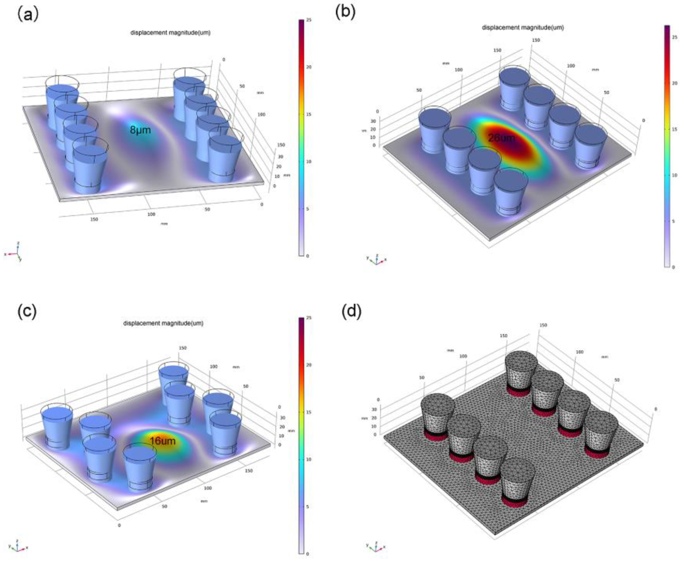
The superposition of vibrations is inevitable when multiple vibration sources are added to the same object. However, determining parameters such as vibration application mode, application position, and amplitude can be challenging. To address this issue, we selected the software COMSOL 6.1 for ultrasonic vibration field simulation in order to verify the experiment’s feasibility and determine the experimental parameters. The multiple vibrator ultrasonic imposition method mainly consists of two types: cross arrangement and column arrangement. Based on the sizes of the welding plate and ultrasonic vibrator, a single-sided four-vibrator arrangement was set up as shown in Figure 2. Each individual vibrator had an amplitude of 6 μm. By applying fixed constraints between the vibrators and plate, we established that vibrations in the z-axis direction would transfer to the plate with an amplitude of 6 μm. According to simulation results (Figure 2), it was observed that by placing eight vibrators with an amplitude of 6 μm at the center of the array, maximum ultrasonic amplitude could reach up to 26 μm within a larger range (considering laser welding process requirements and equipment width; minimum distance from both sides of array was set to 100 mm). This implies that several low-amplitude ultrasonic vibrators can be overlapped to create a larger range with higher amplitudes. Furthermore, the central amplitude size is primarily influenced by the distance between the two arrays, as depicted in Figure 2a Specifically, when the n between the sides of the vibrator array is set to 130 mm, the central amplitude measures only 8 μm.
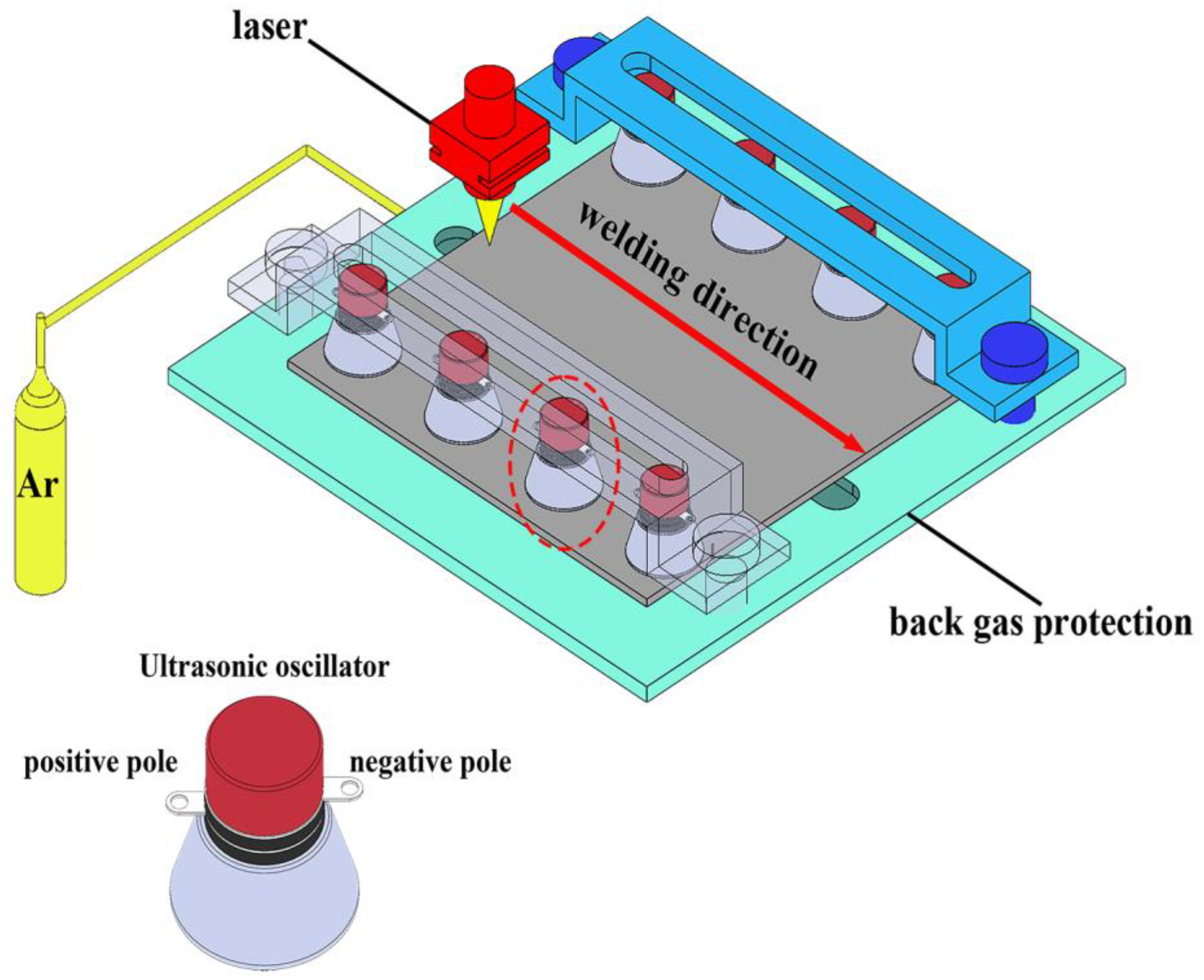
Considering that amplitude is the primary factor influencing grain refinement, in order to achieve equiaxed crystal microstructure, the simulation results suggest controlling the amplitude size of the weld position by adjusting the distance between two columns of vibrators. The vibration intensity of the weld molten pool surface was measured using a laser doppler vibrometer. Ultrasonic-assisted welding experiments were conducted with four different amplitude groups (0, 10 μm, 20 μm, and 25 μm). The experimental setup comprised an ultrasonic system, a laser welding system, and a test platform. Direct melting of the welding material was chosen for the experiment, the laser welding power was 2.4 KW, and the laser spot diameter was 0.5 mm. We designed an ultrasonic generator capable of producing longitudinal vibrations at a power of 160 W and an intrinsic frequency of 28 kHz. The single oscillator amplitude can reach up to 6 μm. The ultrasonic head was positioned on top of the test plate and secured to the experimental platform through a slotted hole, as shown in Figure 3.
To prevent oxidation of the beta titanium alloy during the welding process, the test plate was subjected to acid washing using a mixture of hydrofluoric acid and nitric acid to eliminate the surface oxide film. Additionally, before welding, the surface was meticulously cleaned with acetone. During the welding process, high-purity argon (99.99%) was employed as a shielding gas to safeguard both sides of the joints. The ventilation volumes for front and back protection were set to 15 L/min and 10 L/min respectively, while ensuring that the residence time of shielding gas before and after welding remained consistent at 5 s.
The metallographic samples were prepared by etching with Kroll reagent for a duration of 10 s. The microstructure was examined using an optical microscope (OM, Leica DM4M, Leica Microsystems, Wetzlar, Germany) and a scanning electron microscope (SEM, Japan-JEOL-JSM-IT500, JEOL, Tokyo, Japan). The phase composition was characterized using X-ray diffraction analysis (XRD, Panalytical Aenris, DKSH, Zürich, Switzerland), scanning and analyzing angle range of 20–80°, scanning speed of 2° min−1. Electron backscatter diffraction (EBSD) was employed to capture the morphology, and the resulting EBSD data were processed using ATEX 4.1.1 software. Finally, room temperature tensile tests were conducted on an electronic universal testing machine (ITW-INSTRON5969, Instron, Norwood, MA, USA), the tensile test was carried out at a speed of 2 mm min−1 three times. The schematic diagram of the tensile specimen is shown in Figure 4. These steps and instrumentation were employed to comprehensively observe and evaluate the microstructure and mechanical properties of beta titanium alloys during the welding process, aiming to gain insights into the impact of ultrasonic-assisted welding on joint properties.

3. Results and Discussion

3.1. Microstructure

Under the same corrosion conditions, the morphologies of laser-welded joints with different ultrasonic amplitudes were revealed. Figure 5a shows the corrosion morphology of the laser welded joint without ultrasonication, while Figure 5b,c show the high magnification SEM images of the weld and the heat-affected zone near the base material. According to Figure 5a, the weld exhibits a single β phase. The heat-affected zone is a dual-phase structure of α phase and β phase, but unlike the α phase in the base metal, which presents a rod-like shape, a spherical α phase is observed in Figure 5c. This is due to the fact that during the laser welding process, the α phase is dissolved in the β phase due to the temperature in the molten pool being much higher than the transition temperature point of the beta titanium alloy, which prevents it from precipitating out during rapid cooling. Under the influence of heat radiation, the α phase inside the heat-affected zone undergoes spheroidization.
Figure 5d,e,g demonstrate the laser-welded joints at ultrasonic amplitudes of 10 μm, 20 μm, and 25 μm, respectively. It can be seen that after adding ultrasonic vibration, the top half of the welded joint gradually decreases while the bottom half gradually increases at different ultrasonic amplitudes. This is due to the fact that when laser welding is performed without ultrasonic vibration, the high-power laser causes the metal vapor to be enriched in the plate, and it is difficult for the liquid metal to flow downwards due to the pressure of the metal vapor, which results in the formation of a weld that is wide at the top and narrow at the bottom. However, the addition of ultrasonic vibration enhances the downward movement of the liquid metal by promoting forced convection within the liquid metal [20,21].
Figure 5f shows the XRD pattern of the weld with and without ultrasonication, and Figure 5h,i shows the high-magnification SEM map of the weld and the heat-affected zone near the base material under a 25 μm ultrasonic amplitude. No α phase is detected in Figure 5h, which is verified by the diffraction peaks of only β phase in the result of the weld XRD under the ultrasonic vibration in Figure 5f, and the phase in the weld is still not a single β phase. Near the heat-affected zone of the base material is a two-phase microstructure, but the content of the α phase is significantly reduced, which is due to the application of ultrasonic vibration to promote heat transfer, making the temperature gradient lower and the temperature distribution more uniform; the temperature is also higher, so the width of the heat-affected zone increases the α phase partially back to the melt.
In addition, in Figure 5f, compared to the standard peak of the β phase, it can be seen that the peak intensity of the β-phase grain in the {200} plane without ultrasonication is significantly higher than that of the standard peak of the β phase in the {200} plane, which suggests that the β-phase grain at the laser-welded weld without ultrasonication may have a strong texture in the {200} plane.

3.2. β-Phase Orientation

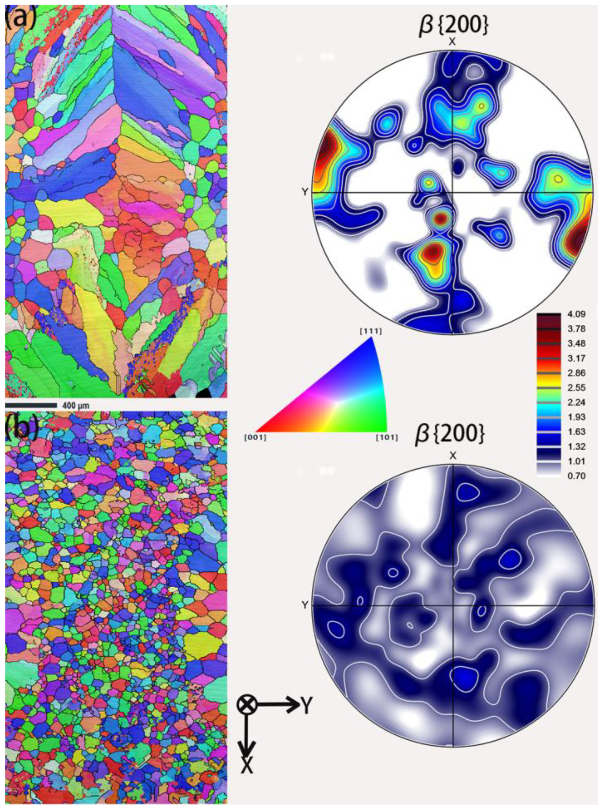
In beta titanium alloys, after heat treatment, a Burgers relationship exists between the β phase and the α phase, while the grain orientation of the α phase modulates the material properties by influencing the grain size and growth direction [2,22,23,24]. The texture strength of the β phase before heat treatment significantly affects the orientation of the precipitated α phase [25]. Based on the analysis of the XRD data in Figure 5f, it is possible that texture forms in the {200} direction in laser welds without ultrasonic treatment. Therefore, we analyzed the grain orientation and weaving of β grains in the weld separately. Figure 6a,b show the orientation distribution function (ODF) plots of the LBW weld and the weld with the addition of M-ULW and their corresponding polar plots in the {200} direction. By dividing the data analysis using the open source software ATEX, these plots show that the β grains in the weld are significantly weakened with the application of ultrasonic vibration in the {200} direction and are more uniform and finer equiaxed. Weakening the texture in the {200} direction helps to weaken the structural anisotropy in the weld, thereby improving the mechanical properties of the material in all directions.

3.3. Effect of Ultrasonic Amplitude on the Grain Morphology of Joint Β

Figure 7a–d demonstrate the superpositions of grain sizes of welds welded with 0–25 μm ultrasonic amplitudes under the same liner conditions as the ATEX treatment. The red grain boundaries indicate small-angle grain boundaries with orientation differences between 2° and 15°, while the black grain boundaries indicate large-angle grain boundaries with orientation differences exceeding 15°. Figure 7e shows the average grain size and its standard deviation at the joint and weld. In order to accurately describe the internal grain condition inside the weld and to take into account the effects caused by different ultrasonic amplitudes on the grain size of the joints, we observed the joints in Figure 7a,b at a magnification of 40 times, while Figure 7c,d show a magnification of 30 times.
According to Figure 7, with the increase in ultrasonic amplitude, the decrease in columnar crystals in the joint is obvious, and the equiaxed grains increase. Figure 7a shows the laser welded joints when no ultrasonication is applied, and a columnar crystal morphology is predominantly present in the weld. In Figure 7b, it is observed that when the ultrasonic amplitude is 10 μm, the content of equiaxial crystals in the joint reaches 95%, and the weld has only a small amount of residual columnar crystal grains, which are present close to the fusion line. It is worth noting that the distribution of equiaxial crystals in the upper and lower parts of the weld is not uniform. When the ultrasonic amplitude reaches 20 μm, all the grains in the joint show an equiaxial structure, the grains near the fusion line of the weld are larger and wrapped by small crystals on both sides, and the grain sizes in the upper and lower parts of the weld are uniform, as shown in Figure 7c. However, when the ultrasonic amplitude reaches 25 μm, depression occurs in the center of the joint, and many small-angle grain boundaries appear in the surrounding grain boundaries. This is due to the fact that ultrasonic vibrations act on the dendrites formed during the solidification of the molten pool, causing the refined dendrites to break up and disperse within the weld along with the molten pool [26]. Ultrasonic vibration induces the generation of a large number of gas bubbles within the melt pool, leading to a violent collapse of the bubbles, which results in a localized excitation wave that is able to rapidly crush nearby dendrites into smaller fragments within a few tens of milliseconds, which can serve as embryonic particles for grain formation [27]. At the same time, a large number of bubbles bursting will produce high temperatures to raise the temperature of the molten pool and the compensation flow; the temperature increases to help debris nucleation, and the compensation flow will affect the flow of liquid metal in the molten pool so that the bubbles are uniformly distributed in the weld seam, so that the weld seam within the grain is refined and uniform. However, if the ultrasonic amplitude exceeds a certain limit, it will destroy the molten pool metal filling type, resulting in welding defects.
In Figure 7e the statistics of the average grain size and standard deviation of joints at different amplitudes are shown. As can be seen from the figure, along with the increase in the ultrasonic amplitude, the average grain size and standard deviation of joints and welds show a decreasing trend. It is worth noting that when the ultrasonic amplitude is 25 μm, compared with the average grain size of joints and welds with an ultrasonic amplitude of 20 μm, there is no significant change, and the standard deviation increases instead. Additionally, we noticed that the number of large and small angular grain boundaries in the weld increased significantly after the application of ultrasonic amplitude. This suggests that the difference in the joints leading to Figure 3 is due to the increase in large and small angles with ultrasonic amplitude.

3.4. Mechanical Properties and Analysis

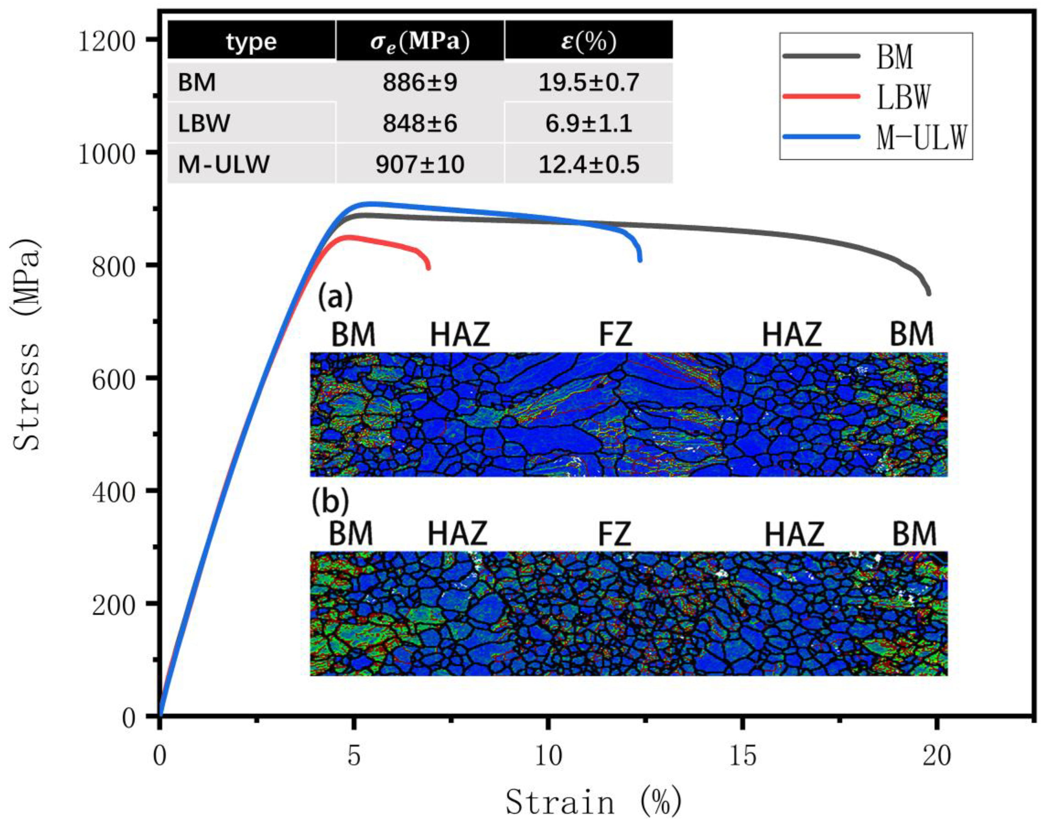
The tensile performance curves of the base material, LBW joints, and M-ULW joints at room temperature are shown in Figure 8. The strength and plasticity of beta titanium alloy deteriorated substantially after laser welding, and the location of fracture was the weld; additionally, the elongation rate changed from the original 19.5% to 6.9%, the base material was selected from the rolled plate without heat treatment, and the strength decrease was not obvious. After the application of ultrasonic-assisted welding, the location of fracture was the weld edge and the connection with the heat-affected zone, and the elongation rate improved to 12.4%, which was 1.8 times the elongation rate of the laser-welded joints. The elongation increased to 12.4%, which is 1.8 times the elongation of laser welded joints, and the strength increased to 907 MPa, which exceeds that of the base material.
Figure 8a shows the average orientation deviation (KAM) of LBW joints, and Figure 8b shows the average orientation deviation (KAM) of M-ULW joints. The green area in the figure is the higher density dislocation area because the base material is the hot rolled state plate without heat treatment, so it contains a large number of dislocations, and these dislocations in the plastic deformation process are conducive to the crystal slippage, recrystallization mechanism, and enhance the plastic deformation ability of the material [28]. In the heat-affected zone, due to the welding temperature, absorption of internal defects occur during dynamic recrystallization, so there is little dislocation. For LBW joints during the welding process, after rapid warming, there is large welding stress inside the weld after welding, the dislocation content is a small and the distribution of β-grain-transformation coarse columnar grains after welding is uneven, the lack of reinforcing phases in the microstructure α leads to joint strength and plasticity deterioration. In addition, the laser welding beta titanium alloy process causes a rapid temperature shift at the joint, which may lead to a small amount of α phase not being dissolved in the β grain, and this residual α phase, to a certain extent, will also lead to the deterioration of the plasticity.
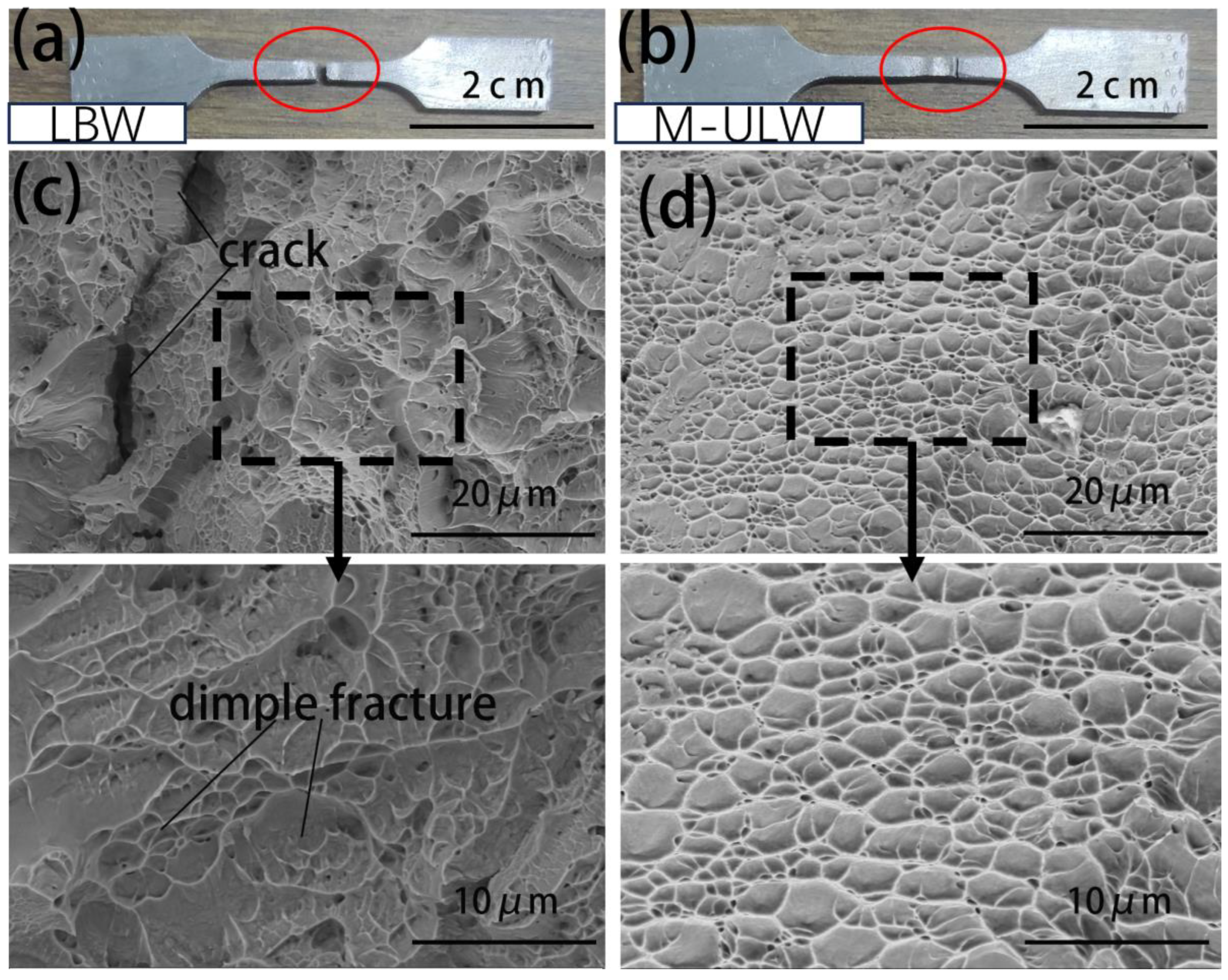
Figure 9 shows the fracture toughness test fracture surfaces of two welds, LBW and M-ULW, at different magnifications. From Figure 9a the LBW joint is shown as a tensile fracture location schematic with the fracture location in the middle of the weld. Figure 9b shows the tensile fracture location of M-ULW, and the fracture location is the edge of the weld and the connection with the heat-affected zone. The LBW weld produces a large area of irregular columnar grains, which is prone to stress concentration, and in the deformation process, the deformation of the weld at various locations is not uniform, resulting in a reduction in plasticity, which can be verified by the non-uniform toughness nests and cracks in the fracture surface topography of the LBW fracture in Figure 9c. In the weld of M-ULW, the grains are fine and uniform, and each grain deforms uniformly under load, as shown in Figure 9d; the grains in the heat-affected zone grow up under the influence of high temperature, which is different from the internal grain size of the weld, leading to the fracture location in the vicinity of the connection between the heat-affected zone and the weld.
For M-ULW joints compared to LBW joints, the molten pool of high temperature remains for a long time, internal defects are fewer, subject to the ultrasonic action of the molten pool of the mechanical stresses generated when the weld contains a larger number of dislocations, and uniformly distributed, and the fine grain reinforcement weaving strength is reduced. Fine grain strengthening, weaving strength weakening effect, strength, and plasticity are improved.

4. Conclusions

  • Multiple vibrator ultrasonic assistance welding of beta titanium alloys at a laser power of 2.4 kW and a spot diameter of 0.5 mm resulted in defect-free welded joints.
  • The introduction of ultrasonic vibration changed the temperature gradient in the molten pool, but the resulting temperature change was not sufficient to change the phase composition of the weld.
  • The significant reduction of the weld width after the introduction of ultrasonic vibrations is attributed to the fact that the introduction of ultrasonic vibrations promotes forced convection in the molten pool. The difference between the surface of the weld and the surface of the base metal is mainly due to the recrystallization of the β grain and remelting of the α phase under the action of temperature, whereas the difference in the surface at different amplitudes is due to the difference in the content of grain boundaries.
  • Based on the cavitation effect produced by ultrasonic vibration in the molten pool, the average grain size of the β phase in the weld decreases with the increase of the ultrasonic amplitude, but it is not a linear relationship, and uniformly distributed fine grains are obtained at an amplitude of 20 μm, and the grains in the weld are not further refined when the amplitude is increased to 25 μm.
  • After the introduction of ultrasonic vibration, the plasticity and strength of the joints are improved, which is due to the strengthening effect caused by grain refinement, and at the same time, the ultrasonic vibration causes the proliferation of dislocation in the joints, and the weakening of structural anisotropy caused by the weakening of weaving in the {200} direction, so that the joints in the tensile process obtain a better resistance to deformation.
  • The improvement of joint performance makes the fracture location of the tensile specimen change from the middle of the weld in the LBW joint to the vicinity of the connection between the welded joint and the heat-affected zone.

Author Contributions

P.D., S.Z. and C.Z. developed the concept for this study. Laboratory experiments and formal analysis were performed by S.W. and L.G. The original draft was written by S.W. and P.D. and reviewed and edited by P.D.; P.D., F.C. and S.Z. were responsible for supervision, investigation and project administration. P.D., S.Z. and C.Z. contributed to funding acquisition and resource deployment. All authors have read and agreed to the published version of the manuscript.

Funding

This study was funded by the Key Research and Development Program of Shanxi Province (202102150401003).

Data Availability Statement

The original contributions presented in the study are included in the article, further inquiries can be directed to the corresponding authors.

Acknowledgments

Thanks to Bofei Fu and Guoting Liu for their great support during the experiments.

Conflicts of Interest

Author Fei Chai was employed by the company Shxi Fenxi Heavy Industry Co., Ltd. The remaining authors declare that the re-search was conducted in the absence of any commercial or financial relationships that could be construed as a potential conflict of interest.

References

  1. Banerjee, D.; Williams, J.C. Perspectives on Titanium Science and Technology. Acta Mater. 2013, 61, 844–879. [Google Scholar] [CrossRef]
  2. Balachandran, S.; Kumar, S.; Banerjee, D. On recrystallization of the α and β phases in titanium alloys. Acta Mater. 2017, 131, 423–434. [Google Scholar] [CrossRef]
  3. Balachandran, S.; Kashiwar, A.; Choudhury, A.; Banerjee, D.; Shi, R.; Wang, Y. On variant distribution and coarsening behavior of the α phase in a metastable β titanium alloy. Acta Mater. 2016, 106, 374–387. [Google Scholar] [CrossRef]
  4. van Bohemen, S.; Kamp, A.; Petrov, R.; Kestens, L.; Sietsma, J. Nucleation and variant selection of secondary α plates in a β Ti alloy. Acta Mater. 2008, 56, 5907–5914. [Google Scholar] [CrossRef]
  5. Wang, X.; Li, W.; Ye, Q.; Yang, X.; Ma, T.; Vairis, A. Linear friction welding of a beta titanium alloy: Experimental investigations on microstructure evolution and mechanical properties. Sci. Technol. Weld. Join. 2020, 25, 625–636. [Google Scholar] [CrossRef]
  6. Liu, H.; Fujii, H. Microstructural and mechanical properties of a beta-type titanium alloy joint fabricated by friction stir welding. Mater. Sci. Eng. A 2018, 711, 140–148. [Google Scholar] [CrossRef]
  7. Guo, Z.; Ma, T.; Yang, X.; Tao, J.; Li, J.; Li, W.; Vairis, A. In-situ investigation on dislocation slip concentrated fracture mechanism of linear friction welded dissimilar Ti17(α+β)/Ti17(β) titanium alloy joint. Mater. Sci. Eng. A 2023, 872, 144991. [Google Scholar] [CrossRef]
  8. Tal-Gutelmacher, E.; Eliezer, D.; Boellinghaus, T. Hydrogen Behavior in GTA Welded Ti-6Al-4V and Beta-21S Aerospace Applic-Ative Titanium Alloys; Beijing International Materials Week: Beijing, China, 2006; pp. 1413–1420. [Google Scholar]
  9. Liu, X.; Graff, K.F. Ultrasonic metal forming: Materials. Power Ultrason. 2023, 243–275. [Google Scholar] [CrossRef]
  10. Buddery, A.; Wang, G.; Yu, Z.; Dargusch, M.; Nabulsi, S. Microstructure Characterization of Laser Welded near-β titanium Al-loy ‘TLM’ under Different Process Conditions. In Proceedings of the 7th Pacific Rim International Conference on Advanced Materials and Processing, Cairns, Australia, 2–6 August 2010; pp. 2146–2149. [Google Scholar]
  11. Anis, A.L.; Talari, M.K.; Babu, N.K.; Ismail, M.H.; Ram, G.J.; Arif, I.A.M. Grain refinement of Ti-15V-3Cr-3Sn-3Al metastable β titanium alloy welds using boron-modified fillers. J. Alloys Compd. 2018, 749, 320–328. [Google Scholar] [CrossRef]
  12. Lu, J.; Lu, H.; Xu, X.; Yao, J.; Cai, J.; Luo, K. High-performance integrated additive manufacturing with laser shock peening–induced microstructural evolution and improvement in mechanical properties of Ti6Al4V alloy components. Int. J. Mach. Tools Manuf. 2020, 148, 103475. [Google Scholar] [CrossRef]
  13. Ramirez, A.; Qian, M.; Davis, B.; Wilks, T.; StJohn, D. Potency of high-intensity ultrasonic treatment for grain refinement of magnesium alloys. Scr. Mater. 2008, 59, 19–22. [Google Scholar] [CrossRef]
  14. Shu, D.; Sun, B.; Mi, J.; Grant, P.S. A High-Speed Imaging and Modeling Study of Dendrite Fragmentation Caused by Ultrasonic Cavitation. Met. Mater. Trans. A 2012, 43, 3755–3766. [Google Scholar] [CrossRef]
  15. Ning, F.; Cong, W. Ultrasonic vibration-assisted (UV-A) manufacturing processes: State of the art and future perspectives. J. Manuf. Process. 2020, 51, 174–190. [Google Scholar] [CrossRef]
  16. Zhang, K.; He, C.; Liu, D.; Yan, C.; Niu, H.; Yang, Z.; Bao, Y. Effect of heat input on microstructure and tensile properties of laser welded Ti–3Al–6Mo–2Fe–2Zr alloy joint. J. Mater. Res. Technol. 2022, 17, 1652–1661. [Google Scholar] [CrossRef]
  17. Zhaoxin, D.; Guolong, L.; Xiaoming, C.; Huimin, L.; Jun, C. Effect of Pre-aging on Microstructure and Mechanical Properties of Ti-3.5Al-5Mo-6V-3Cr-2Sn-0.5Fe Alloy. Rare Met. Mater. Eng. 2019, 48, 1904–1908. [Google Scholar]
  18. Zhang, S.; Wang, Q.; Cheng, X.; Han, J.; Zhang, W.; Zhang, C.; Wu, J. Static Recrystallization Behavior and Texture Evolution during Annealing in a Cold Rolling Beta Titanium Alloy Sheet. Metals 2022, 12, 899. [Google Scholar] [CrossRef]
  19. Du, Z.; Xiao, S.; Liu, J.; Lv, S.; Xu, L.; Kong, F.; Chen, Y. Hot Deformation Behavior of Ti-3.5Al-5Mo-6V-3Cr-2Sn-0.5Fe Alloy in α + β Field. Metals 2015, 5, 216–227. [Google Scholar] [CrossRef]
  20. Qiao, J.; Wu, C.; Li, Y. Numerical and experimental investigation of keyholing process in ultrasonic vibration assisted plasma arc welding. J. Manuf. Process. 2020, 50, 603–613. [Google Scholar] [CrossRef]
  21. Mohammed, S.M.; Paul, T.; John, D.; Zhang, C.; Agarwal, A. Understanding the role of ultrasonic cavitation assisted casting of boron nitride nanotube-reinforced aluminum matrix composite. J. Mater. Res. Technol. 2023, 25, 2405–2418. [Google Scholar] [CrossRef]
  22. Zhao, Z.; Wang, Q.; Hu, Q.; Liu, J.; Yu, B.; Yang, R. Effect of β (110) texture intensity on α-variant selection and microstructure morphology during β→α phase transformation in near α titanium alloy. Acta Mater. 2017, 126, 372–382. [Google Scholar] [CrossRef]
  23. Cayron, C.; Artaud, B.; Briottet, L. Reconstruction of parent grains from EBSD data. Mater. Charact. 2006, 57, 386–401. [Google Scholar] [CrossRef]
  24. Ye, Q.; Li, X.; Tayyebi, M.; Assari, A.H.; Polkowska, A.; Lech, S.; Polkowski, W.; Tayebi, M. Effect of heat treatment parameters on microstructure evolution, tensile strength, wear resistance, and fracture behavior of Ni–Ti multilayered composites produced by cross-accumulative roll bonding. Arch. Civ. Mech. Eng. 2022, 23, 27. [Google Scholar] [CrossRef]
  25. Liu, S.; Tayyebi, M.; Assari, A.H.; Polkowska, A.; Lech, S.; Polkowski, W. Microstructure, Texture and Tensile Properties of Nickel/Titanium Laminated Composites Produced by Cross Accumulative Roll Bonding Process. Met. Mater. Int. 2023, 29, 3630–3644. [Google Scholar] [CrossRef]
  26. Wei, X.; Li, X.; Zhang, L.; Lv, Q. Effect of in-situ ultrasonic impact treatment on flow and solidification behavior of laser metal deposition: By finite element simulation. Int. J. Heat Mass Transf. 2022, 192, 122914. [Google Scholar] [CrossRef]
  27. Jia, H.; Cao, L.; Fu, S.; Wen, H.; Ma, G. Numerical simulation and experiment for the dynamic behavior of molten pool in ultrasonic-assisted MIG welding. Int. J. Heat Mass Transf. 2023, 215, 124469. [Google Scholar] [CrossRef]
  28. Zuo, Z.; Haowei, M.; Yarigarravesh, M.; Assari, A.H.; Tayyebi, M.; Tayebi, M.; Hamawandi, B. Microstructure, Fractography, and Mechanical Properties of Hardox 500 Steel TIG-Welded Joints by Using Different Filler Weld Wires. Materials 2022, 15, 8196. [Google Scholar] [CrossRef]
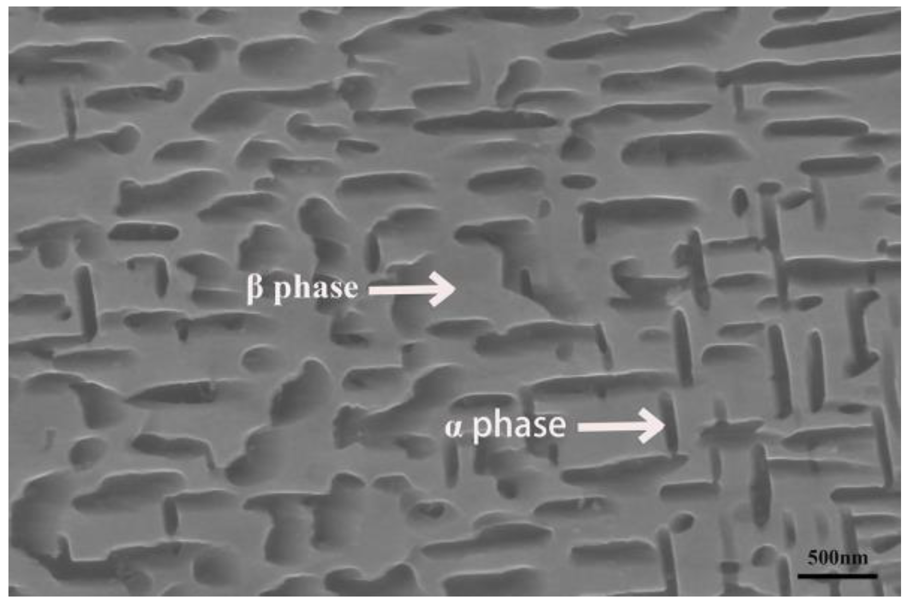
Figure 1. Optical microstructure of the base material.
Metals 14 00422 g001
Figure 2. Simulation results with COMSOL software: (a) column arrangement, distance between two side vibrators of 130 mm; (b) column arrangement, distance between two side vibrators of 100 mm; (c) cross arrangement; (d) mesh sectioning.
Metals 14 00422 g002
Figure 3. Schematic diagram of multi-vibrator ultrasonic-assisted welding.
Metals 14 00422 g003
Figure 4. Schematic of samples used for tensile testing: (a) sampling location; (b) tensile specimen size.
Metals 14 00422 g004
Figure 5. Morphology and analysis of laser welded joints under different ultrasonic amplitudes: (a) topography of laser welded joints without ultrasonication; (b) microstructure of weld without ultrasonication; (c) microstructure of the heat-affected zone of the base material without ultrasonic proximity; (d) ultrasonic amplitude of 10 μm; (e) ultrasonic amplitude of 20 μm; (f) physical analysis of M-ULW and LBW; (g) ultrasonic amplitude of 25 μm; (h) microstructure of weld with ultrasonication; and (i) microstructure of the heat-affected zone of the base material with ultrasonic proximity.
Metals 14 00422 g005
Figure 6. Weld orientation analysis: (a) inverse pole figure maps and the contoured pole figures established along the z-axis direction of the β phase of the weld without ultrasonication; (b) inverse pole figure maps and the contoured pole figures established along the z-axis direction of the β phase of the weld with ultrasonication.
Metals 14 00422 g006
Figure 7. Grain refinement results of joints at different ultrasonic amplitudes:(a) 0 μm; (b) 10 μm; (c) 20 μm; (d) 25 μm; (e) grain size statistics and standard deviation at different amplitudes.
Metals 14 00422 g007
Figure 8. BM, LBW, M-ULW tensile curves and joint KAM plots: (a) LBW joints (b) M-ULW joints.
Metals 14 00422 g008
Figure 9. The fracture surfaces after fracture toughness testing pertaining to all welds at different magnifications:(a) schematic diagram of LBW fracture location; (b) schematic diagram of M-ULW fracture location; (c) LBW fracture surface morphology; (d) M-ULW fracture surface morphology.
Metals 14 00422 g009
Table 1. Chemical composition of the base material.
ElementTiAlMoVCrSnFe
wt.%79.403.785.265.792.642.510.61
Disclaimer/Publisher’s Note: The statements, opinions and data contained in all publications are solely those of the individual author(s) and contributor(s) and not of MDPI and/or the editor(s). MDPI and/or the editor(s) disclaim responsibility for any injury to people or property resulting from any ideas, methods, instructions or products referred to in the content.