
Research on and Application of Feature Recognition and Intelligent Retrieval Method for Multi-Component Alloy Powder Injection Molding Gear Based on Partition Templates
Abstract
:1. Introduction
- Section 1 provides a summary of the research conducted with the existing methods for feature parameterization.
- Section 2 introduces the process of this method and the gear partition templates defined by this method in detail.
- Section 3 introduces the two key algorithms of feature recognition and intelligent retrieval. Section 3.1 introduces the tooth profile parameter calculation formula and structure parameter identification process in detail, and Section 3.2 introduces the similarity calculation formula and weight automatic adjustment.
- Section 4 is the intelligent system implementation and results discussion. The intelligent system is developed based on the NX platform. The experimental result shows the superiority of the system.
- Section 5 is the conclusion. In this section, the advantages of the method and the future work are detailed and summarized.
2. Feature Identification and Intelligent Retrieval Method
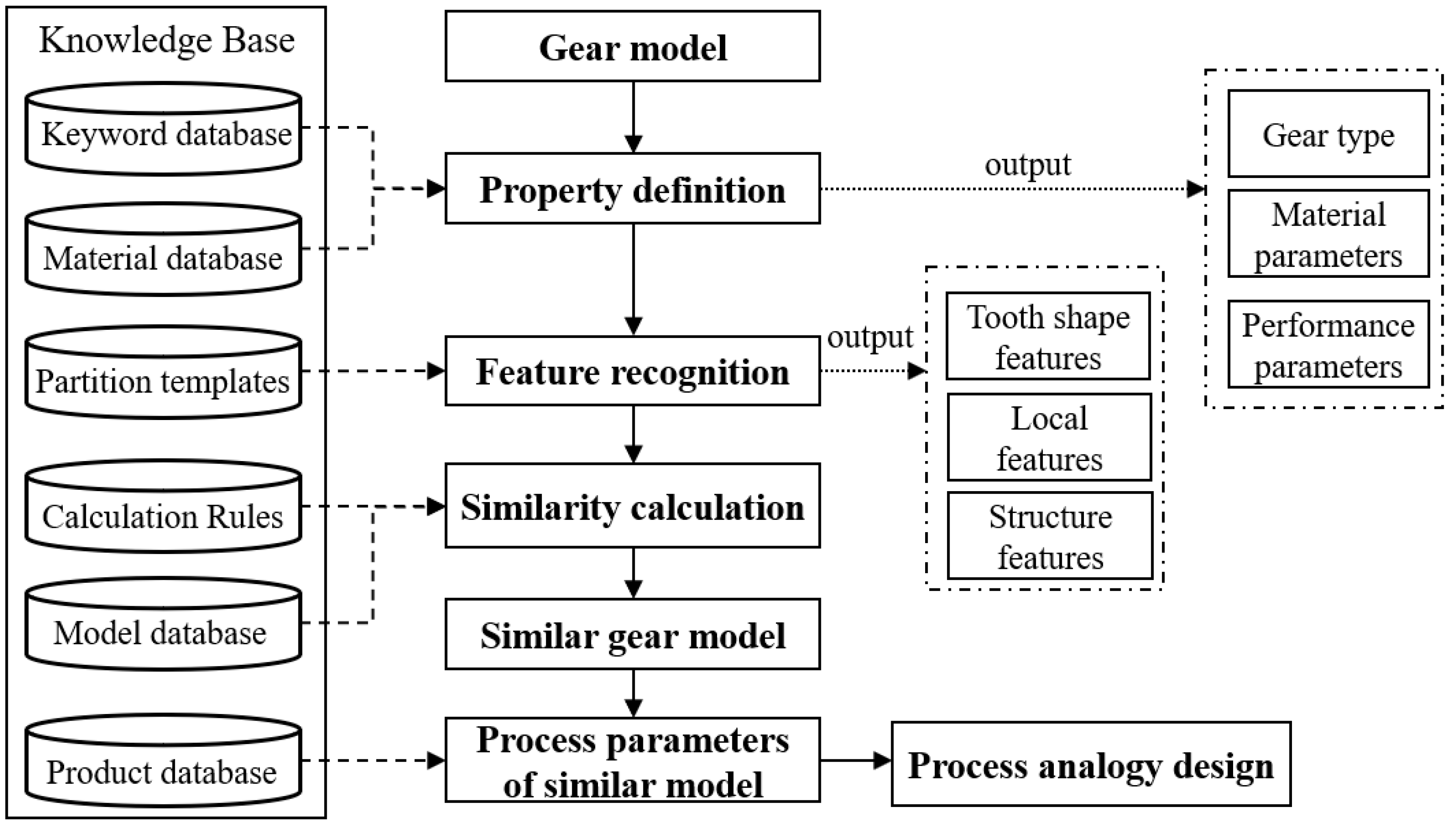
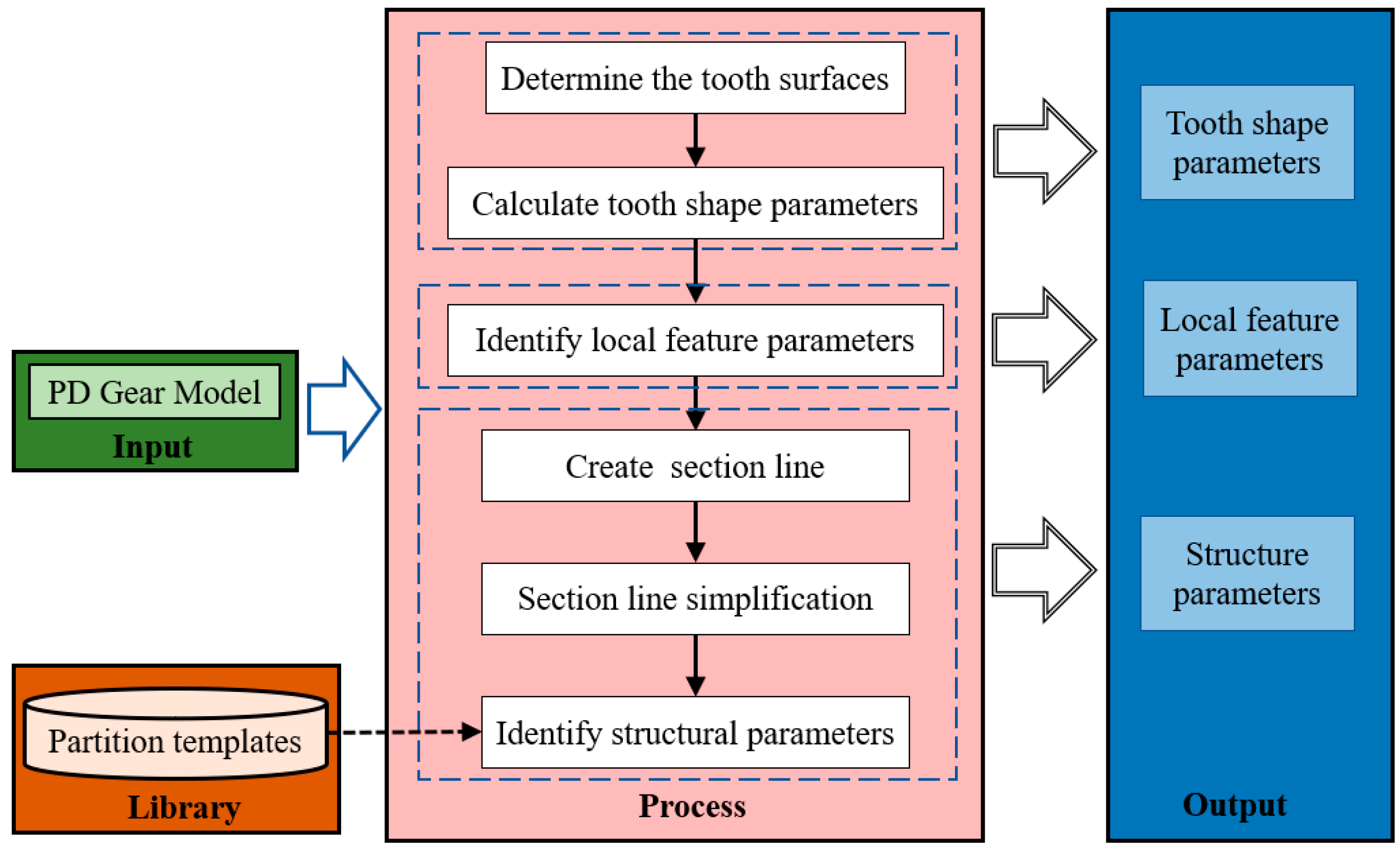
2.1. Flow of the Method
- To reduce the dependence on the designer’s experience: through summarizing the method and experience, establish the gear feature partition templates, realize the digitization of the gear model, and intelligently retrieve the similar model through the similarity calculation and greatly reduce the dependence on the designer’s experience;
- To improve design efficiency: the use of mature process information of similar parts is helpful to realize the analogical design of the metal powder injection molding process for multi-alloy cylindrical spur gears and can significantly improve the design efficiency;
- To reduce design errors: utilizing intelligent retrieval based on similarity matching with mature knowledge at the product level can help control design error to a lower level.
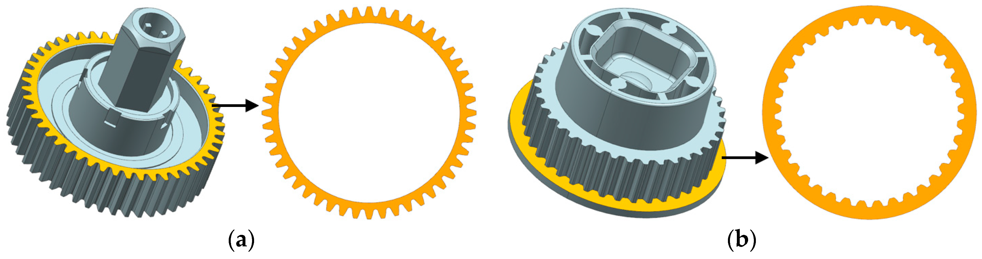
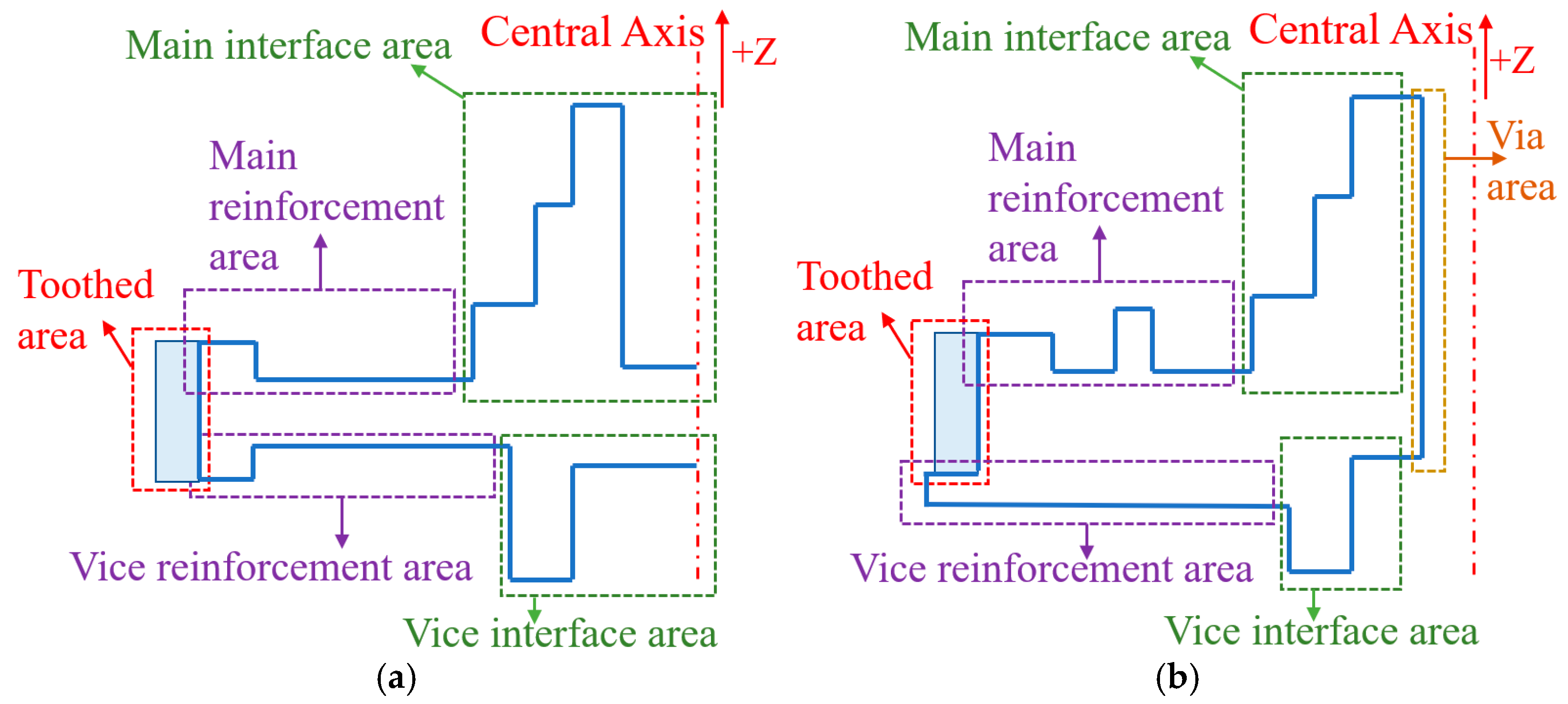
2.2. Partition Templates
2.2.1. Via Area
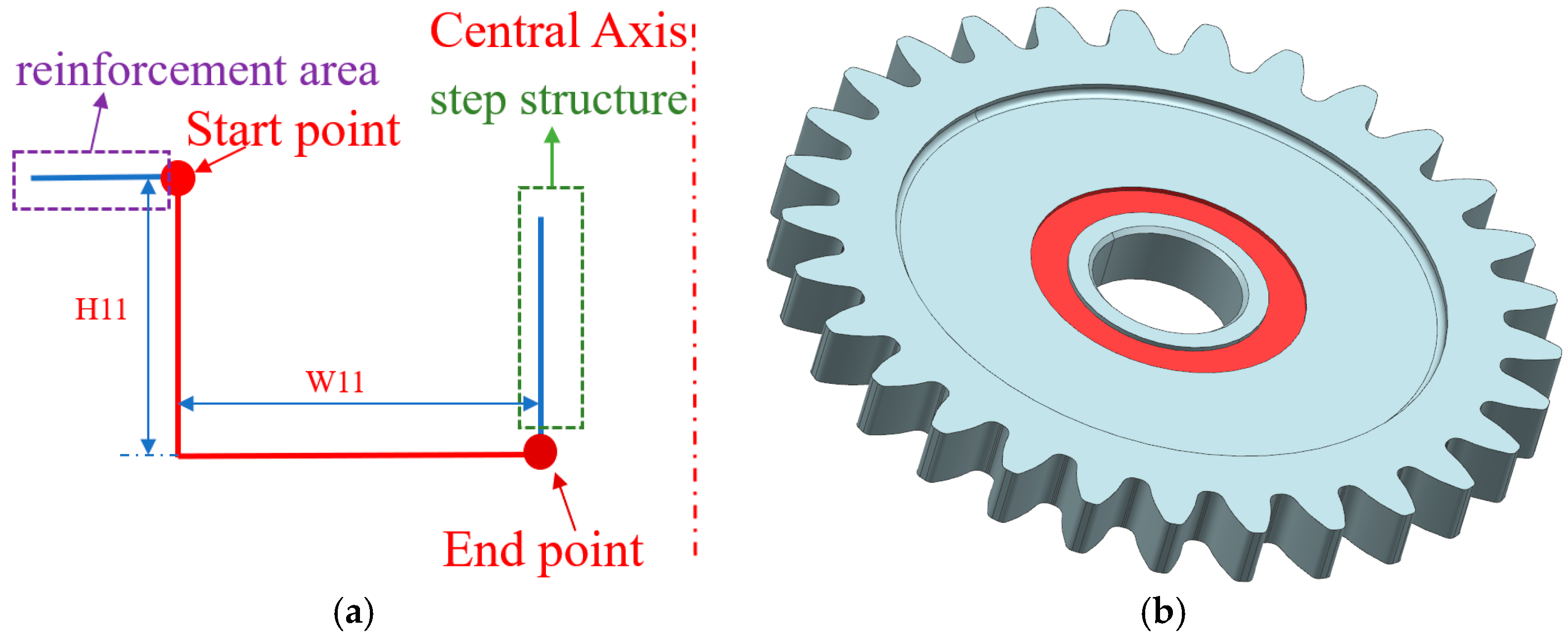
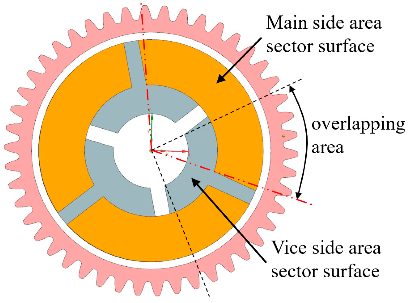
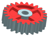
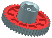
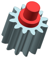
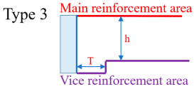
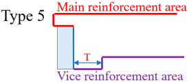
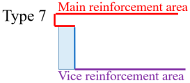
2.2.2. Reinforcement Area
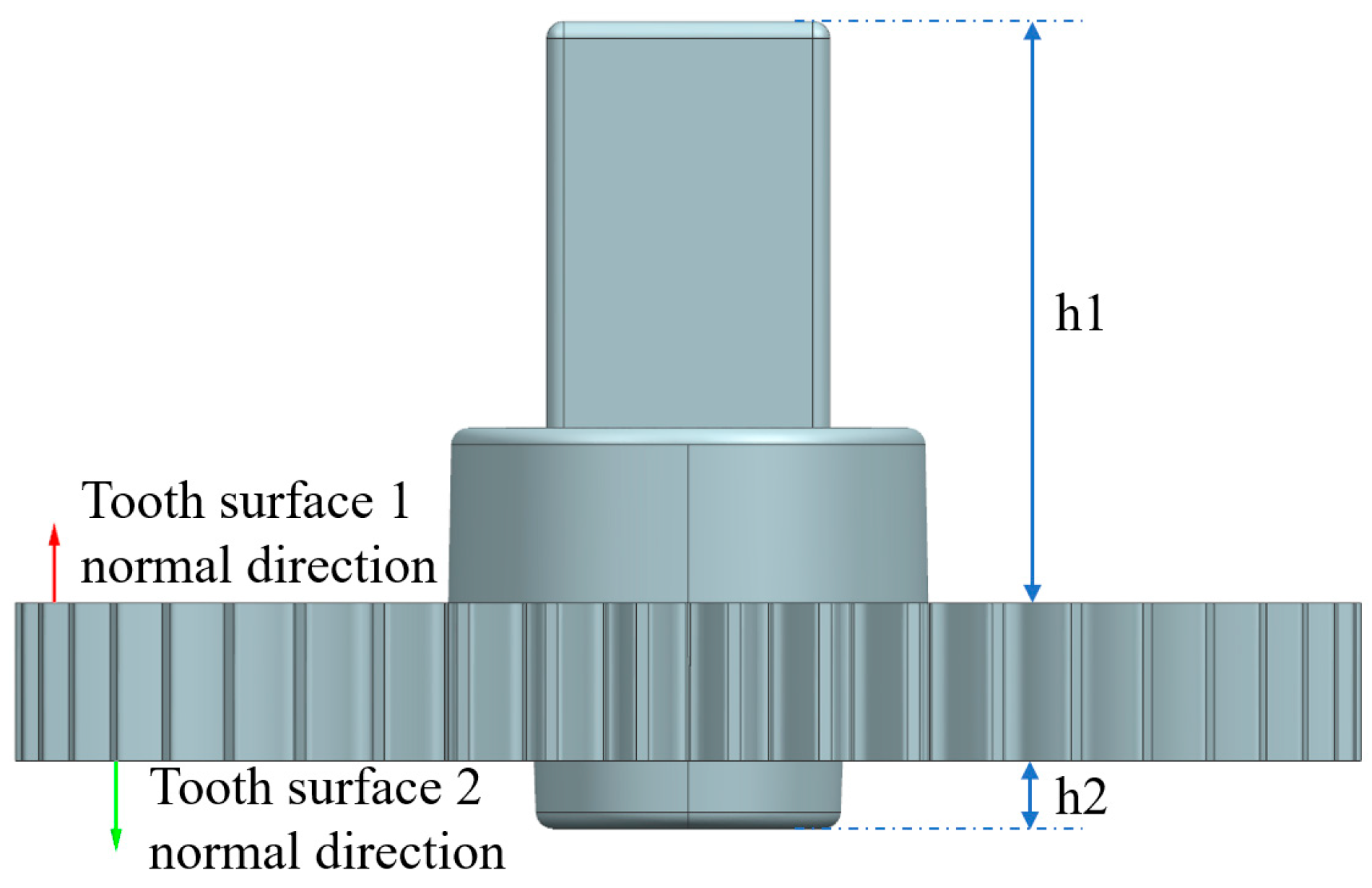
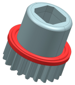
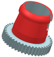
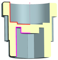
2.2.3. Interface Area
2.2.4. Overall Structure
3. Key Algorithm
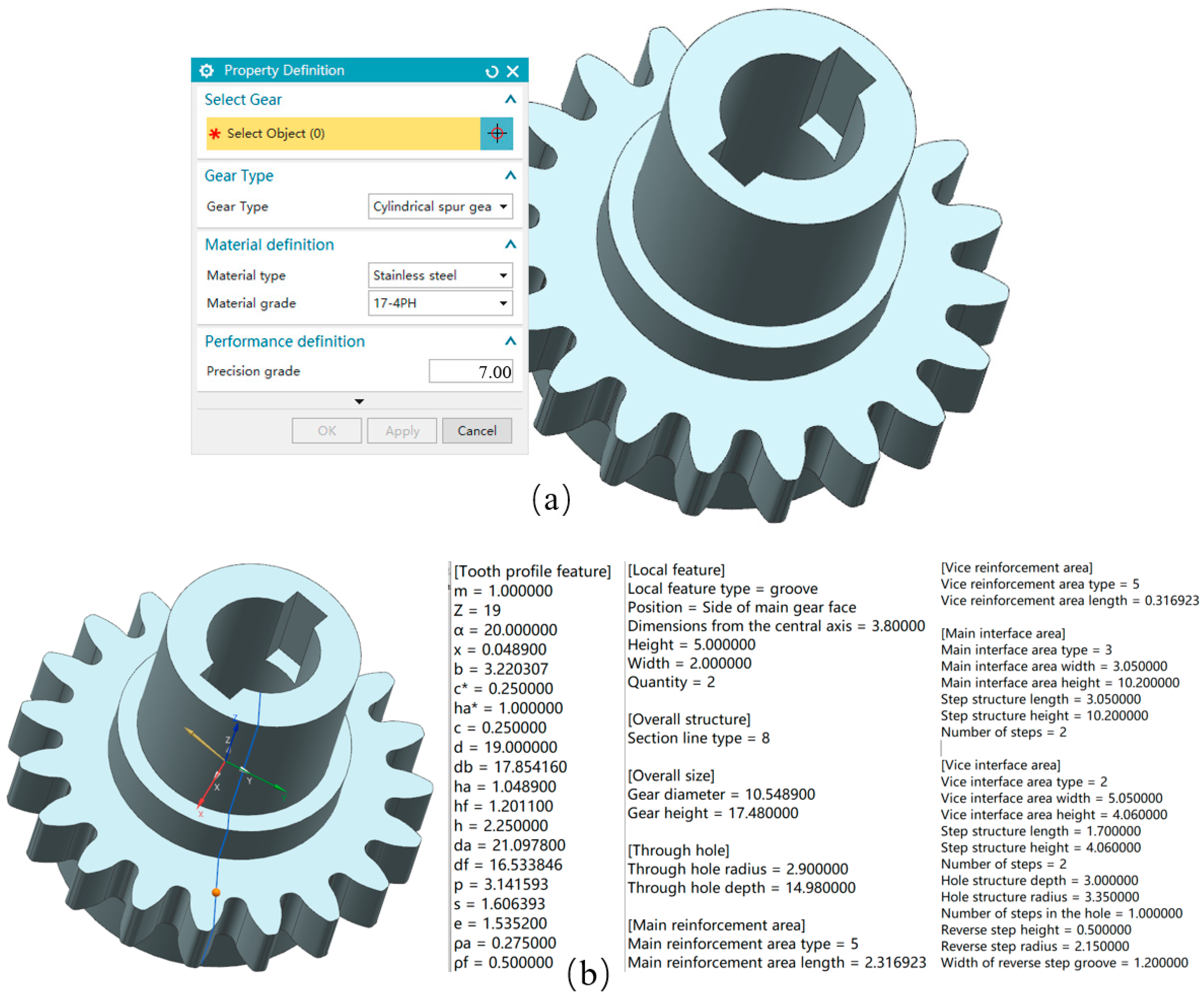
3.1. Feature Recognition
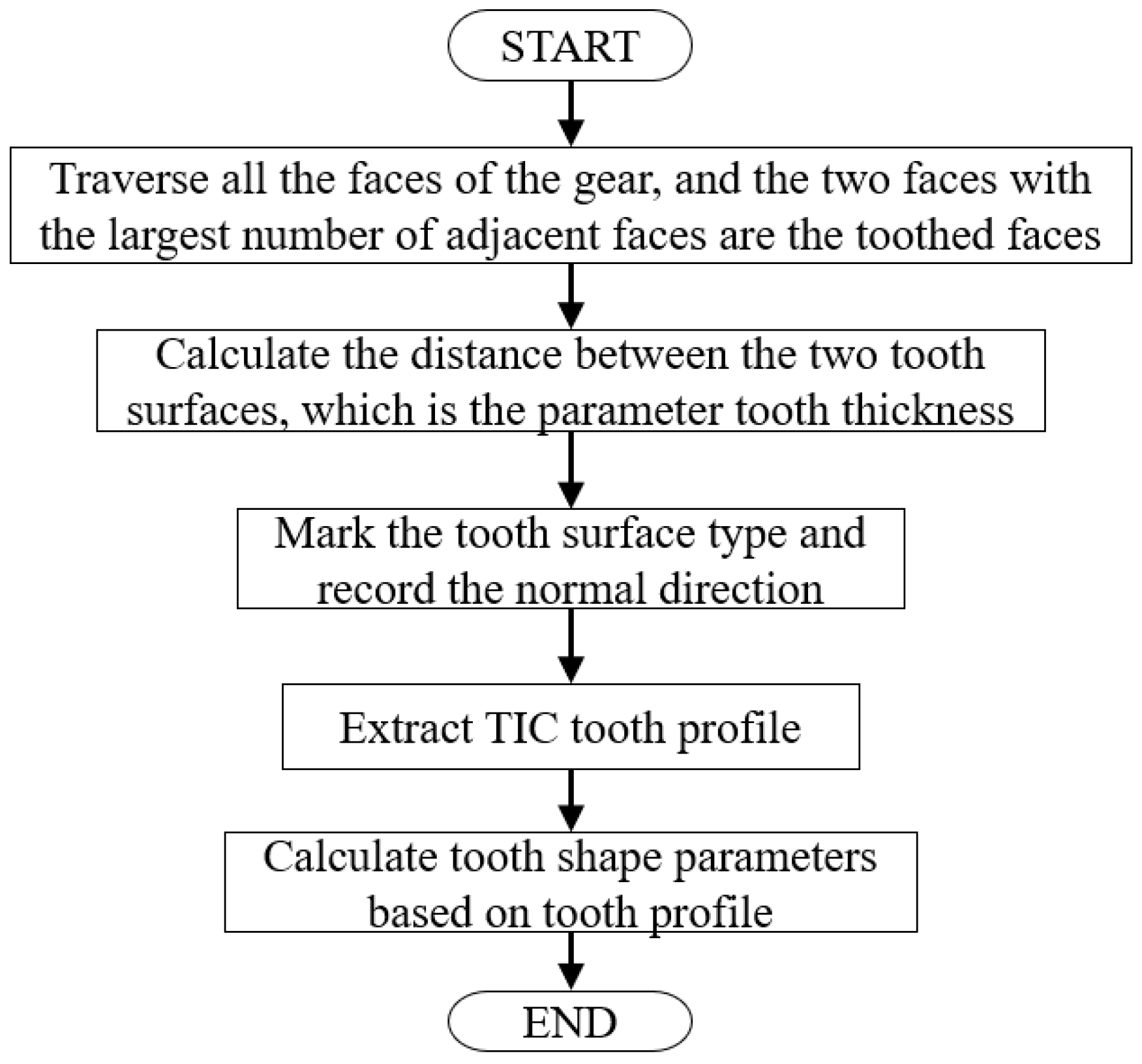
3.1.1. Tooth Shape Parameters and Local Feature Parameters
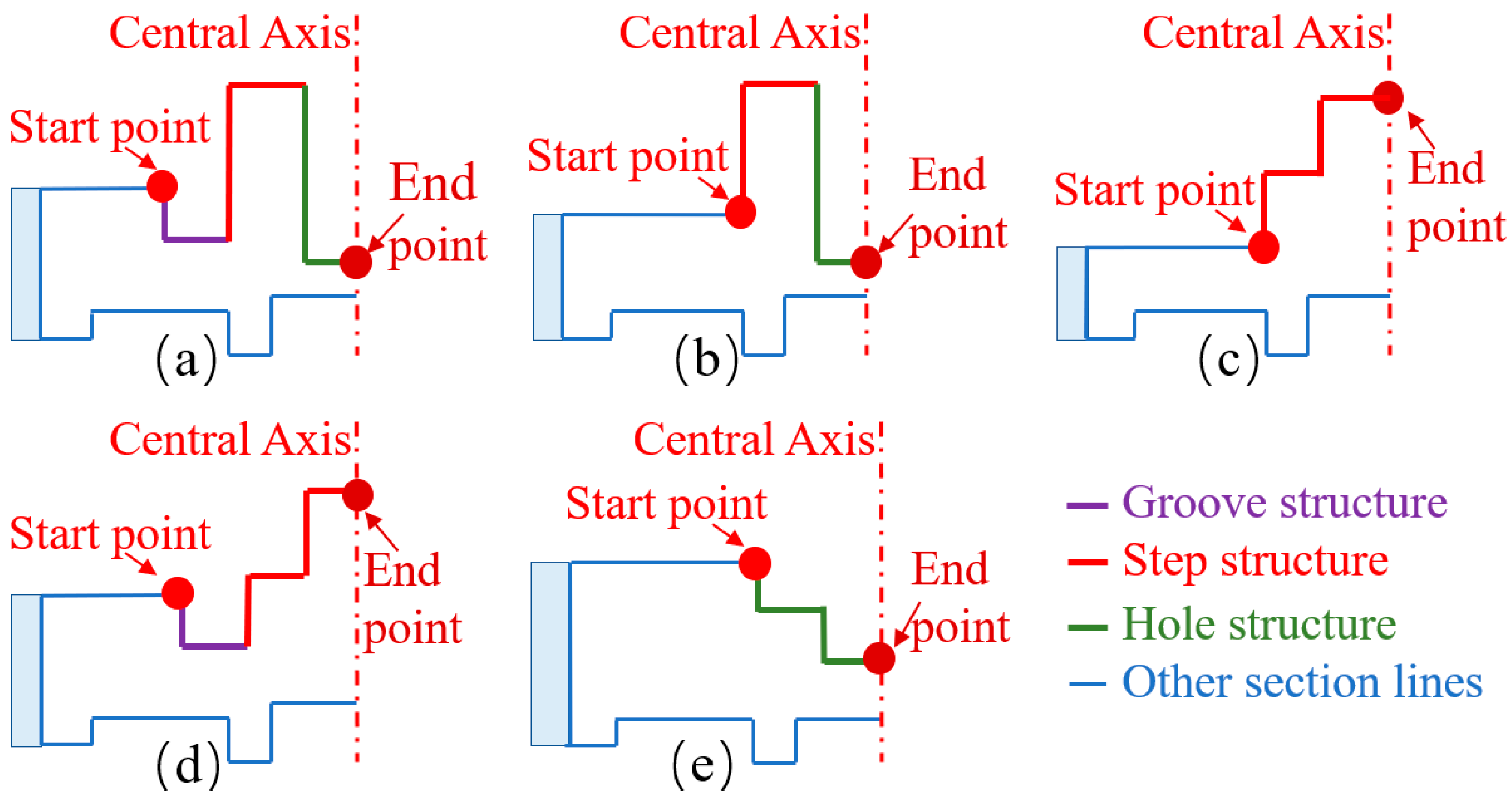
3.1.2. Structure Parameters
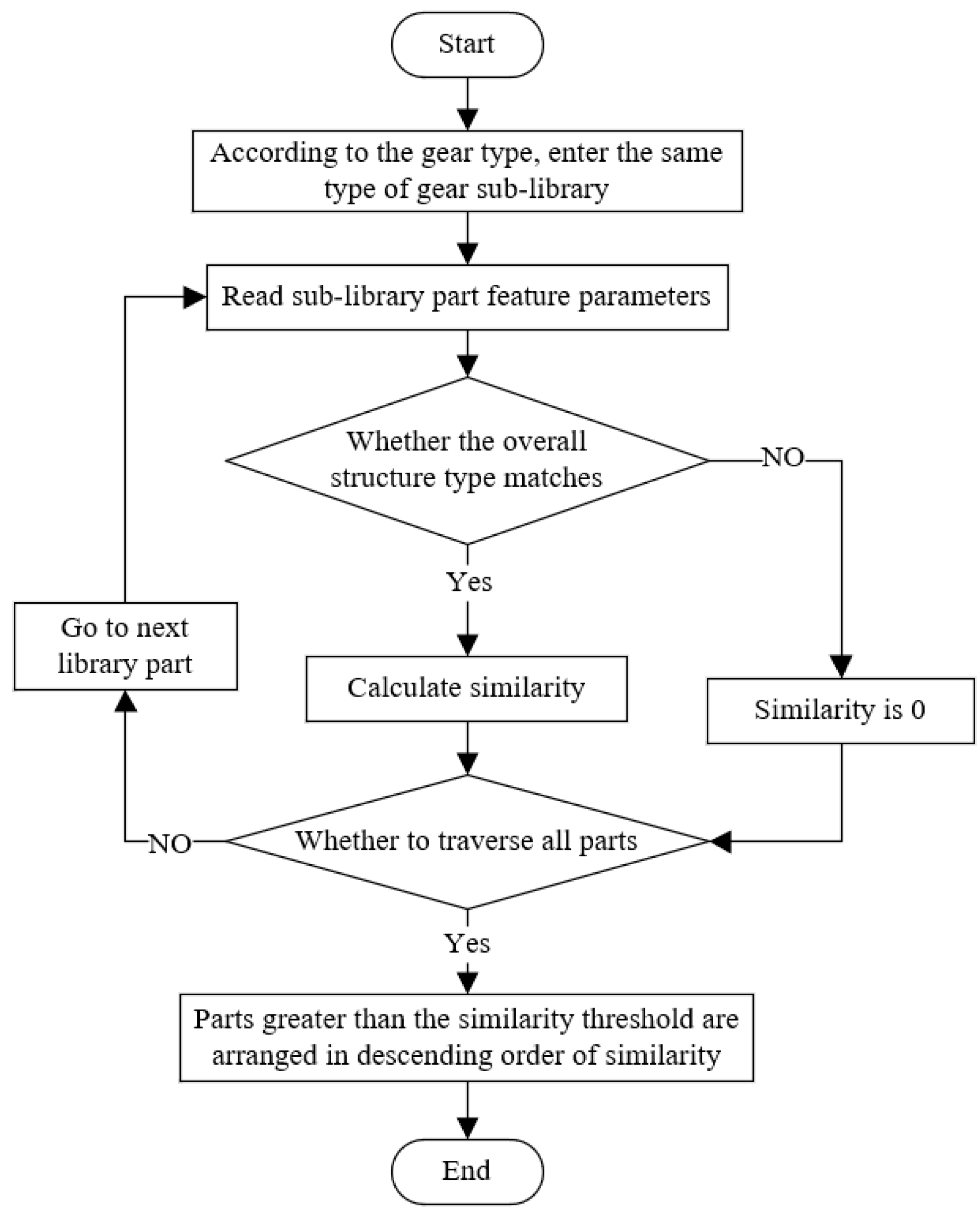
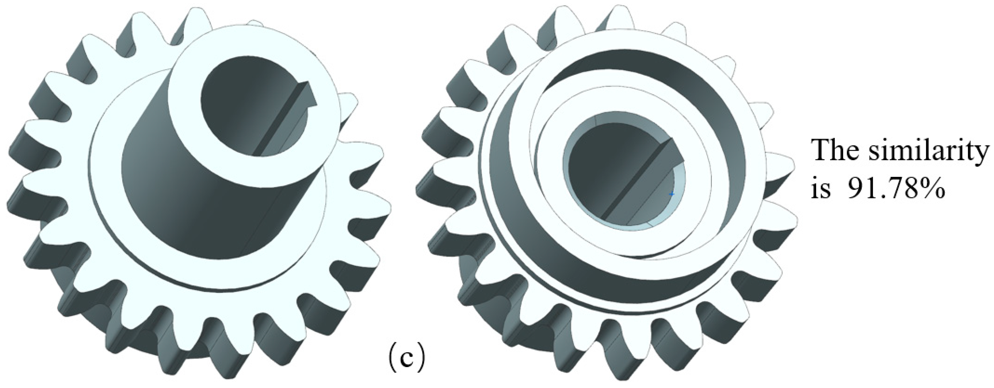
3.2. Intelligent Retrieval of Similar Gear Models
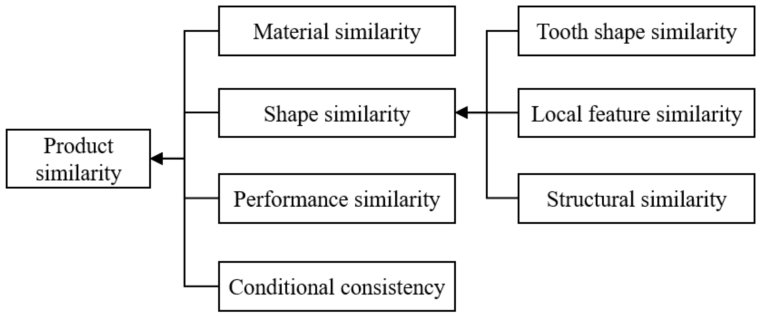
3.2.1. Similarity Calculation Formula
3.2.2. Weight Adjustment
- If the structures of the two gears being compared are inconsistent, calculate the similarity based on the gear structure with a larger number of partition templates;
- If the two gears being compared lack a certain area, the weight of the area is evenly distributed to other areas. For instance, if a gear structure lacks a main interface area, distribute the weights of the main interface area evenly to the overall structure, the main reinforcement area, the vice reinforcement area, and the vice interface area;
- If neither gear has a via area, add the weight of the via area to the overall structure weight;
- If the slider structure does not exist in the two gear interface areas involved in the calculation, the weight will be added to the step structure weight in the interface area;
- If the hole reverse structure is not present in the interface areas of both gears, add the weight to the hole structure weight in the interface area.
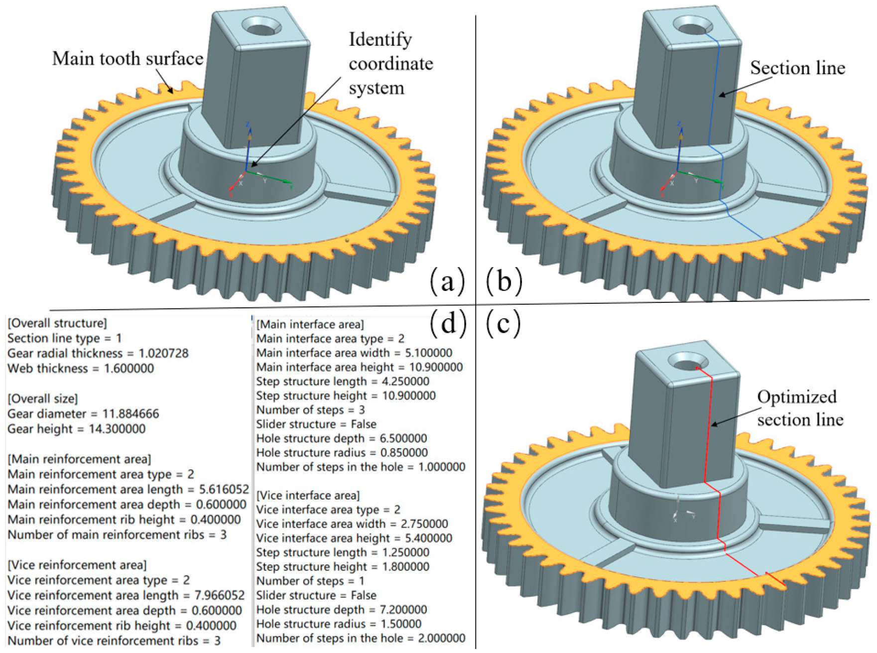
4. System Implementation and Case Studies
5. Conclusions
Author Contributions
Funding
Data Availability Statement
Acknowledgments
Conflicts of Interest
References
- Lee, J.; Choi, H.; Sohn, J.; Lee, G.; Park, D.; Kim, J. Statistical analysis for transmission error of gear system with mechanical and thermal deformation uncertainties. Appl. Sci. 2021, 11, 6582–6608. [Google Scholar] [CrossRef]
- Hu, R.; Luo, H.; Xu, C.; Guo, Y.; Yang, Y. Research on the influence on the addendum-shortened-coefficient of the first-last teeth of incomplete driving gear to avoid interference. Heliyon 2024, 10, e23996. [Google Scholar] [CrossRef]
- Zhang, H.; Zhang, N. Polymer Micro Injection Molding. Encycl. Mater. Plast. Polym. 2022, 3, 565–574. [Google Scholar]
- Piotter, V. Micro Metal Injection Molding (MicroMIM); Woodhead Publishing Limited: Swaston, UK, 2012; pp. 307–337. [Google Scholar]
- Ammosova, L.; Mönkkönen, K.; Suvanto, M. Precise fabrication of microtextured stainless steel surfaces using metal injection moulding. Precis. Eng. 2020, 62, 89–94. [Google Scholar] [CrossRef]
- Liao, Y.; Li, Z.; Li, X.; Su, S.; Zhao, Y.; Li, Y.; Wu, J.; Luo, Y.; Wu, C. Effect of Sintering Temperature on Microstructure and Mechanical Properties of Fe–4Ni–0.8Mo–0.6C Steel Small-Module Gears Fabricated by Micrometal Injection Molding. Steel Res. Int. 2023, 94, 2200886. [Google Scholar] [CrossRef]
- Basir, A.; Sulong, A.B.; Jamadon, N.H.; Muhamad, N. Feedstock properties and debinding mechanism of yttria-stabilized zirconia/stainless steel 17-4PH micro-components fabricated via two-component micro-powder injection molding process. Ceram. Int. 2021, 47, 20476–20485. [Google Scholar] [CrossRef]
- Tay, B.Y.; Loh, N.H.; Tor, S.B.; Ng, F.L.; Fu, G.; Lu, X.H. Characterisation of micro gears produced by micro powder injection moulding. Powder Technol. 2009, 188, 179–182. [Google Scholar] [CrossRef]
- Yin, H.; Qu, X.; Jia, C. Fabrication of micro gear wheels by micropowder injection molding. J. Univ. Sci. Technol. Beijing Miner. Metall. Mater. 2008, 15, 480–483. [Google Scholar] [CrossRef]
- Naranjo, J.A.; Berges, C.; Campana, R.; Herranz, G. Rheological and mechanical assessment for formulating hybrid feedstock to be used in MIM & FFF. Results Eng. 2023, 19, 101258. [Google Scholar]
- Shimizu, T.; Kitazima, A.; Nose, M.; Fuchizawa, S.; Sano, T. Production of large size parts by MIM process. J. Mater. Process. Technol. 2001, 119, 199–202. [Google Scholar] [CrossRef]
- Zhang, S.; Guan, Z.; Jiang, H.; Wang, X.; Tan, P. BrepMFR: Enhancing machining feature recognition in B-rep models through deep learning and domain adaptation. Comput. Aided Geom. Des. 2024, 111, 102318. [Google Scholar] [CrossRef]
- Xu, T.; Li, J.; Chen, Z. Automatic machining feature recognition based on MBD and process semantics. Comput. Ind. 2022, 142, 103736. [Google Scholar] [CrossRef]
- Wang, P.; Yang, W.-A.; You, Y. A hybrid learning framework for manufacturing feature recognition using graph neural networks. J. Manuf. Process. 2023, 85, 387–404. [Google Scholar] [CrossRef]
- Zhang, Y.; Luo, X.; Zhang, B.; Zhang, S. Semantic approach to the automatic recognition of machining features. Int. J. Adv. Manuf. Technol. 2016, 89, 417–437. [Google Scholar] [CrossRef]
- Skvortsov, V.; Proletarsky, A.; Arzybaev, A. Feature Recognition Module of the CAPP System. In Proceedings of the 2019 IEEE Conference of Russian Young Researchers in Electrical and Electronic Engineering (EIConRus), Saint Petersburg, Russia; Moscow, Russia, 28–31 January 2019. [Google Scholar]
- Wang, Q.; Yu, X. Ontology based automatic feature recognition framework. Comput. Ind. 2014, 65, 1041–1052. [Google Scholar] [CrossRef]
- Yang, Y.; Fei, L.; Alshehri, A.H.; Zhao, S.; Sun, W.; Teng, S. Joint multi-type feature learning for multi-modality FKP recognition. Eng. Appl. Artif. Intell. 2023, 126, 106960. [Google Scholar] [CrossRef]
- Yang, H.; Lu, W.F. Case adaptation in PROCASE: A case-based process planning system for machining of rotational parts. AI EDAM 1996, 10, 401–419. [Google Scholar] [CrossRef]
- Choi, T.H.; Choi, S.; Na, K.H.; Bae, H.S.; Chung, W.J. Application of intelligent design support system for multi-step deep drawing process. J. Mater. Process. Technol. 2002, 130–131, 76–88. [Google Scholar] [CrossRef]
- Guo, L.; Yan, F.; Li, T.; Yang, T.; Lu, Y. An automatic method for constructing process knowledge base from knowledge graph. Robot. Comput.-Integr. Manuf. 2022, 73, 102222. [Google Scholar] [CrossRef]
- Lu, X.; Zhou, Y.; Cao, Z.; Tang, J. A novel mathematical model for the accurate measurement of face gears by considering the geometric deviations of multiple teeth. Measurement 2024, 231, 114545. [Google Scholar] [CrossRef]
- Lu, Z.; Chen, Y.; Liu, H.; Zhu, C.; Wu, R. A high-power-density design method for polymer gear systems via an adaptive non-dominated sorting genetic algorithm III and surrogate sub-models. Mater. Des. 2024, 240, 112875. [Google Scholar] [CrossRef]
- Mohammed, O.D. A Study of Different Considerations to Meet Gear Design Requirements. Procedia Struct. Integr. 2022, 42, 1607–1608. [Google Scholar] [CrossRef]
- Liu, W.; Zhu, R.; Zhou, W.; Wang, J. Research on feature extraction method for different levels of cracks and pitting in spur gear based on dynamic characteristic templates. Measurement 2024, 228, 114335. [Google Scholar] [CrossRef]
- He, G.; Li, J.; Ding, K.; Zhang, Z. Feature extraction of gear and bearing compound faults based on vibration signal sparse decomposition. Appl. Acoust. 2022, 189, 108604. [Google Scholar] [CrossRef]
- Bachar, L.; Matania, O.; Cohen, R.; Klein, R.; Lipsett, M.G.; Bortman, J. A novel hybrid physical AI-based strategy for fault severity estimation in spur gears with zero-shot learning. Mech. Syst. Signal Process. 2023, 204, 110748. [Google Scholar] [CrossRef]
- Lin, Y.; Xiao, M.; Liu, H.; Li, Z.; Zhou, S.; Xu, X.; Wang, D. Gear fault diagnosis based on CS-improved variational mode decomposition and probabilistic neural network. Measurement 2022, 192, 110913. [Google Scholar] [CrossRef]
- Zhang, S.; He, M.; Zhong, Z.; Zhu, D. An industrial interference-resistant gear defect detection method through improved YOLOv5 network using attention mechanism and feature fusion. Measurement 2023, 221, 113433. [Google Scholar] [CrossRef]
- Wang, Z.; Daeipour, M.; Xu, H. Quantification and propagation of Aleatoric uncertainties in topological structures. Reliab. Eng. Syst. Saf. 2023, 233, 109122. [Google Scholar] [CrossRef]
- Zhang, Y.; Zhang, Y.; He, K.; Li, D.; Xu, X.; Gong, Y. Intelligent feature recognition for STEP-NC-compliant manufacturing based on artificial bee colony algorithm and back propagation neural network. J. Manuf. Syst. 2022, 62, 792–799. [Google Scholar] [CrossRef]
- Li, B.; Zhu, W.; Eynard, B.; Bricogne, M. Researched on the Technology of Machining Simulation. Adv. Mater. Res. 2014, 1039, 390–396. [Google Scholar] [CrossRef]
- Lobov, A.; Tran, T.A. Object-oriented approach to product design using extended NX Open API. Procedia Manuf. 2020, 51, 1014–1020. [Google Scholar] [CrossRef]


| Type | Example | Feature Parameters |
|---|---|---|
 |  | W20: Reinforcement area length H20: Reinforcement area depth H22: Ring rib height |
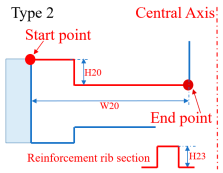 |  | W20: Reinforcement area length H20: Reinforcement area depth H23: Reinforcement rib height N23: Number of Reinforcement ribs |
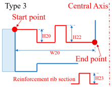 |  | W20: Reinforcement area length H20: Reinforcement area depth H22: Ring rib height H23: Reinforcement rib height N23: Number of Reinforcement ribs |
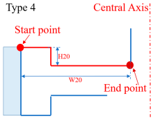 |  | W20: Reinforcement area length H20: Reinforcement area depth |
 |  | W20: Reinforcement area length H22: Ring rib height |
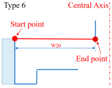 |  | W20: Reinforcement area length |
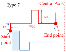 |  | W20: Reinforcement area length T20: Reinforcement area thickness H22: Ring rib height |
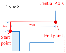 |  | W20: Reinforcement area length T20: Reinforcement area thickness |
| Type | Example | Feature Parameters |
|---|---|---|
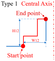 |  | W12: Step structure length H12: Step structure height N12: Number of steps False: No slider structure |
 |  | W12: Step structure length H12: Step structure height N12: Number of steps True: Exists slider structure |
| Type | Example | Feature Parameters |
|---|---|---|
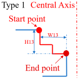 |  | W13: Hole structure radius H13: Hole structure depth N13: Number of steps in the hole |
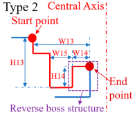 | W13: Hole structure radius H13: Hole structure depth N13: Number of steps in the hole W14: Reverse boss structure radius H14: Reverse boss structure height N14: Number of reverse boss steps W15: Groove width |
| Type | Subtype | Feature Parameters |
|---|---|---|
| Web | 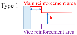 | T: Gear radial thickness h: Web thickness |
 | ||
 | ||
| T |  | T: Gear radial thickness |
 | ||
| Thicken | 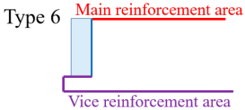 | None |
 | ||
| Normal | 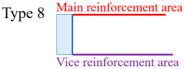 | None |
| Type | Before Optimization | After Optimization |
|---|---|---|
| Removal of round corner |  |  |
| Removal of chamfer |  |  |
| Arc reconstruction | 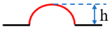 | h < default value |
h ≥ default value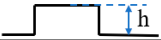 | ||
| Removal of microgroove |  | h < default value |
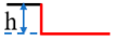 | ||
| Removal of micro convex structure | 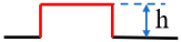 | h < default value |
 | ||
| Removal of thread |  |  |
| Performance Data | Performance Calculation | Retrieve Similar Parts | Mold Opening Cycle | Number of Test Molds |
|---|---|---|---|---|
| Without intelligent CAD system | About 20 min | About 90 min | About 20 days | About 5 |
| With intelligent CAD system | 0.5 min | 1 min | 13 days | 2 |
| Savings (%) | 97.5 | 98.9 | 35 | 60 |
Disclaimer/Publisher’s Note: The statements, opinions and data contained in all publications are solely those of the individual author(s) and contributor(s) and not of MDPI and/or the editor(s). MDPI and/or the editor(s) disclaim responsibility for any injury to people or property resulting from any ideas, methods, instructions or products referred to in the content. |
© 2024 by the authors. Licensee MDPI, Basel, Switzerland. This article is an open access article distributed under the terms and conditions of the Creative Commons Attribution (CC BY) license (https://creativecommons.org/licenses/by/4.0/).
Share and Cite
Kong, Y.; Cui, X.; Zhang, Z.; Liu, Y. Research on and Application of Feature Recognition and Intelligent Retrieval Method for Multi-Component Alloy Powder Injection Molding Gear Based on Partition Templates. Metals 2024, 14, 579. https://doi.org/10.3390/met14050579
Kong Y, Cui X, Zhang Z, Liu Y. Research on and Application of Feature Recognition and Intelligent Retrieval Method for Multi-Component Alloy Powder Injection Molding Gear Based on Partition Templates. Metals. 2024; 14(5):579. https://doi.org/10.3390/met14050579
Chicago/Turabian StyleKong, Yan, Xiaoyi Cui, Zhibing Zhang, and Yuqi Liu. 2024. "Research on and Application of Feature Recognition and Intelligent Retrieval Method for Multi-Component Alloy Powder Injection Molding Gear Based on Partition Templates" Metals 14, no. 5: 579. https://doi.org/10.3390/met14050579