Article

Closed-Cell Aluminum Foam of Improved Sound Absorption Ability: Manufacture and Properties

by
Alexandra Byakova
1,
Svyatoslav Gnyloskurenko
2,*,
Yuriy Bezimyanniy
1 and
Takashi Nakamura
3
1
Institute for Problems of Materials Science, National Academy of Sciences of Ukraine, 3 Krzhyzhanovsky St., 03142 Kiev, Ukraine
2
Physical-Technological Institute of Metals and Alloys, National Academy of Sciences of Ukraine, 34/1 Vernadsky Ave., 03142 Kiev, Ukraine
3
Institute of Multidisciplinary Research for Advanced Materials, Tohoku University, Sendai 980-8577, Japan
*
Author to whom correspondence should be addressed.
Metals 2014, 4(3), 445-454; https://doi.org/10.3390/met4030445
Submission received: 19 April 2014 / Revised: 14 July 2014 / Accepted: 7 August 2014 / Published: 28 August 2014

Abstract

:
The paper presents a new method for the production of the closed-cell Al foams of improved sound absorbing ability. Final heat treatment procedure including heating below the solidus temperature followed by water quenching is proposed as an alternative method to machining, which is used commonly for improvement of the sound absorption coefficient. Several kinds of foams based on AlZnMg-alloys comprising brittle eutectic domains of interdendritic redundant phase have been produced by the Alporas-like melting process to realize the method above. Opening of the closed cell structure required for ensuring high sound absorption ability has been achieved by cracking the walls between neighboring cells, making them gas permeable. They ultimately looked like Helmholtz micro-perforated resonators. Processing parameters and other variables that are favorable both for foaming regime and for final heat treatment are discussed and specified.

Graphical Abstract

1. Introduction

The problem of undesirable and potentially hazardous noise is gaining increased attention from the standpoint of better environment and a more diversified lifestyle. Therefore, thin, lightweight and low-cost materials that can absorb sound waves in wide frequency regions are urgently required. In accordance with theory, the air permeability of the sound absorber is a fundamental requirement for cellular solids to be used for this purpose [1]. Acoustic attenuation in cellular materials is commonly ascribed to combination of certain physical phenomena and, particularly, to viscous losses caused by viscous friction of air and relaxation process in imperfectly elastic material as well. Because of this, part of the sound energy is converted into heat when a sound wave enters porous material. For this purpose, soft polymer foams, mineral fibers, and glass wool are generally used although they have a detrimental effect on human health. Presently, eco-friendly cellular metals and, especially, foamed aluminum of high corrosion resistance have been justified as attractive sound-absorbing materials [2]. Moreover, the great attraction of the above materials lies in their multifunctional ability ensured by a unique combination of absorption ability with high stiffness, lightweight, mechanical isolation, fire protection and chemical stability. That is why there is an extensive interest in the development of reliable and economically effective methods capable for mass production of Al-foams for wide range engineering applications, particularly in sound absorbers [3].
Open-cell Al foams demonstrate quite good sound absorption ability due to the consumption of the sound energy by viscous friction of an air in the interconnected cells and thermal conduction. Closed-cell foams have relatively low absorption ability. Since they are not gas permeable they cannot provide global motion of fluid to solid required for acoustic attenuation by viscous losses due to friction. In addition, closed-cell foams are too stiff to guarantee sound absorption by vibration of their cell walls.
Sound absorption ability of closed-cell Al foams can be significantly improved after modification of their surface and structure. There are several methods capable to serve this purpose, i.e., cutting surface skin, perforation of the surface, opening the closed-cell structure by machining including either drilling of through-holes of 2–10 mm in diameter or partial compression by 10% of foamed plate with breaking the walls between the cells, making them interconnected and gas-permeable [2,4]. However, all of the methods above are not economically effective. Moreover, opening the closed-cell structure by machining of Al-foamed plate leads to impairing their mechanical performance. The paper presents a new method for production of sound absorbing Al foams via an Alporas like route without any further machining operations. The additional effort of the present paper is to illuminate the advantages of the method in terms of its notable effect on multifunctional ability of fabricated Al-foam and, especially, on combination of high sound absorption and constructional strength. Moreover, attention is also drawn to performance capability of the method to reduce the material cost required for fabrication of foams via a conventional Alporas like route.

2. Results and Discussion

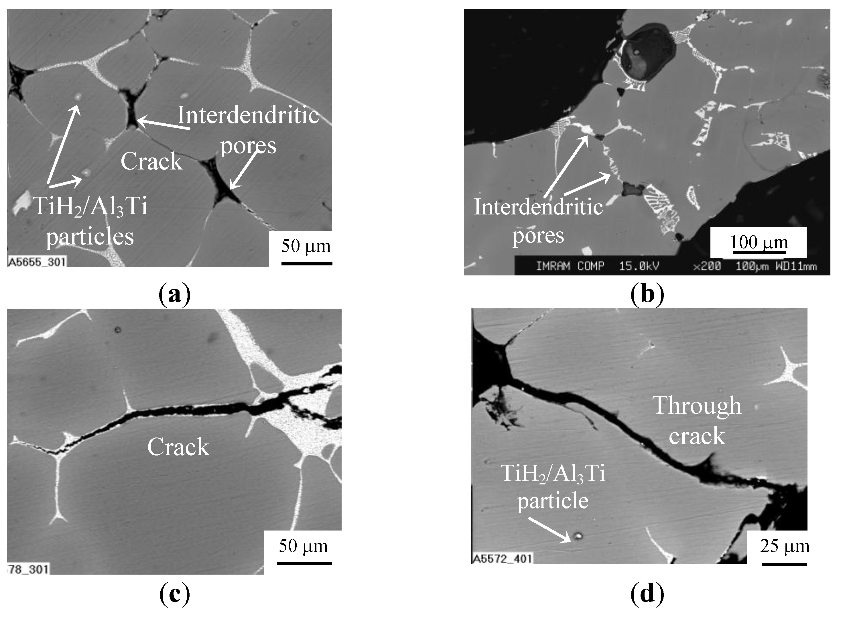
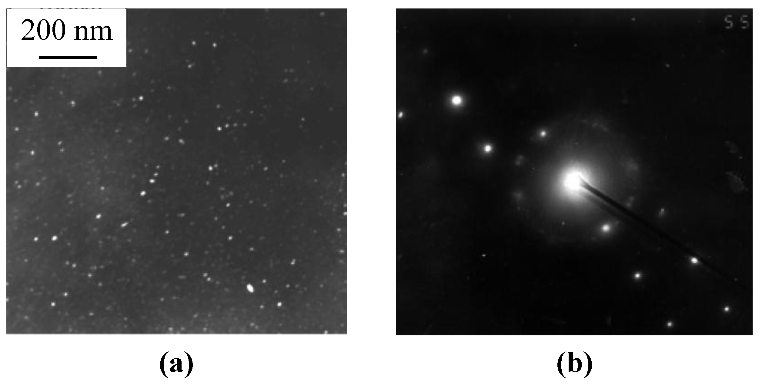
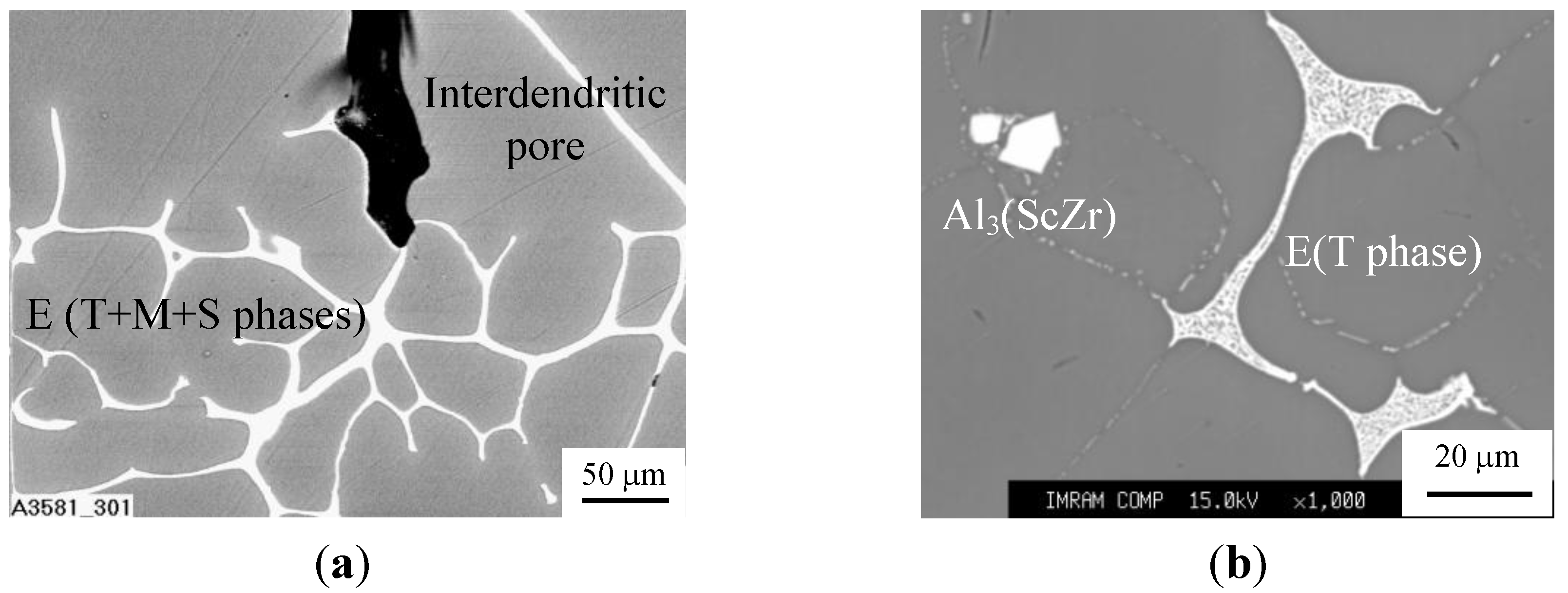
2.1. Material Characterization

Both kinds of foams have cells of spherical shape. The difference is that the foams processed with CaCO3 foaming agent demonstrate mean cell size (D ≈ 1 mm) which is at least two times smaller than for foams produced using TiH2. As it was originally shown [5], presence of solid oxide skin on the surface of cell faces formed due to oxidation reaction between the melt and CO2-gas is primary responsible for fine cellular structure of CaCO3-foam.
As shown in Figure 1a, the microstructure of the cell wall material created just after foaming one or another kind of foams is basically the same as that of the corresponding ZAM alloy.
Figure 1. SEM images for microstructure of cell wall material for (a,c,d) ZAM 1 and (b) ZAM 2 foams processed with no Ca additive and produced using (a,c,d) TiH2 and (b) CaCO3: (a,b) before and (c,d) after final heat treatment.
Metals 04 00445 g001
The main difference is that the network of eutectic domains is modified by Ca when it was used as a thickening additive [6]. When foams were processed with TiH2 foaming agent, foreign particles of partly converted TiH2 and/or its reaction products such as particles/layers of Al2Ti/Al3Ti survive in Al matrix, as can be seen in Figure 1. In addition, Ti dissolves in Al matrix and concentrated within the eutectic domains [6]. As shown in Figure 1a,b, a number of interdendritic pores are revealed in the cell wall material of as-received ZAM foams and, especially, those processed with ZAM 1 alloy. These pores can serve as sites for crack initiation within the brittle redundant phase. Actually, very fine cracks bridging these pores are visible in microstructure of the cell material, as can be seen in Figure 1a. In both kinds of foams, heat treatment according to mode T4 (see Subsection 3.2) creates micrometer sized cracks lengthways the eutectic domains of redundant phase, as can be seen in Figure 1c,d. Moreover, these cracks extend through the cell walls when their thickness becomes comparable with dimension of Al dendrites, opening thereby the closed-cell structure, as shown in Figure 1d. Besides cracking the eutectic domains, mode T6 (see Subsection 3.2) results in precipitation of nanometer-sized intermetallic compounds embedded in an Al matrix. In foams processed with ZAM 1 alloy, nanometer-sized particles of MgZn2 are revealed in the cell wall material, as shown in Figure 2. When foams were processed with ZAM 2 alloy, precipitations of MgZn2 together with nano-sized particles of Al3Sc are found in the Al matrix.
Figure 2. TEM images (dark field) of the cell wall material after heat treatment in line with mode T6 being employed for fabrication of foams based on ZAM 1 alloy: (a) nanometer-sized precipitations and (b) diffraction pattern of MgZn2 particles.
Metals 04 00445 g002

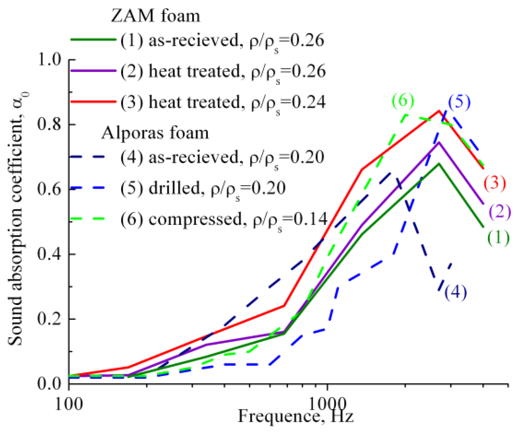
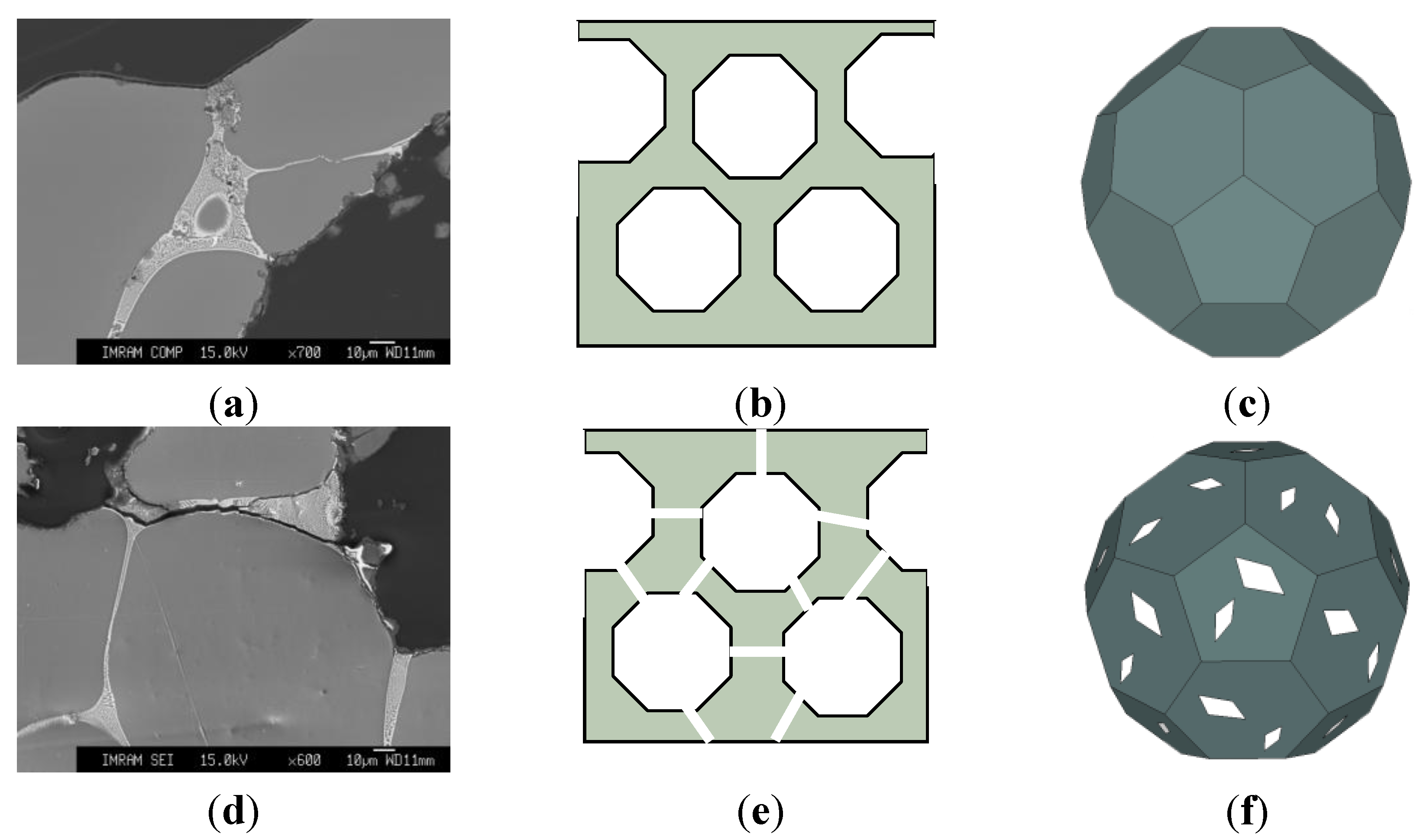
2.2. Correlation of Sound Absorption Ability and Foam Cellular Structure

Sound absorption ability of heat treated ZAM-foams of different relative density is shown in Figure 3 by comparison with Al-foams performed by original Alporas route. It is significant that the extreme value of sound absorption coefficient at normal incidence α0 for as-received ZAM-foam (1) superior to that of as-received Alporas foam (4). This is because the interdendritic porosity and fine cracks are presented in the cell wall material of as-received ZAM-foams, as shown in Figure 1a,b. Moreover, heat treatment (see Subsection 3.2) of ZAM-foams (2,3) causes the extreme values of sound absorption coefficient at normal incidence α0 to rise up. In addition, extreme values of sound absorption coefficient α0 for as-received (1) and heat treated ZAM-foams (2,3) are shifted towards higher frequencies. The above event was recorded for closed-cell foams with sharp-edged cracks in the cell wall material [4,7]. As shown in Figure 3, the same phenomena is observed for Alporas foam after opening closed-cell structure due to breaking the cell walls by machining operation (5,6).
Figure 3. Sound absorption coefficient at normal incidence α0 measured for (1) as-received and (2,3) heat treated foams of ZAM 1 alloy processed with CaCO3 and Ca additive as well as for (4) as-received Alporas foams and those machined by either (5) drilling or (6) partial compression by 10% [4,7], all performed for selected values of relative density and foam thickness about (1–3) 15 mm and (4–6) 10 mm.
Metals 04 00445 g003
These results certify that heat treatment of ZAM-foams guarantees the formation of micrometer cracks lengthways the brittle eutectic domains presented in the cell wall material. As a result, viscous losses by viscous friction of an air, thermal conduction, and relaxation process become greater when sound wave is propagating into thin cracks.
Attention should be paid to the fact that sound absorption coefficient at normal incidence α0 of heat treated ZAM-foams increases with decreasing the relative density from 0.26 to 0.24. A number of interconnected cells rise up with reducing the relative density down to critical value, ρ/ρs ≤ 0.25, implying formation through cracks when the cell wall thickness becomes comparable with dimension of Al dendrites (roughly about 150 μm). Formation of the through cracks allows a maximum opening of the cellular structure, ultimately resulting in greater dissipation of sound wave and, hence, in greater sound absorption management. Figure 3 shows that the values of sound absorption coefficient at normal incidence α0 for heat treated ZAM-foam with ρ/ρs = 0.24 (2) increase in advance over the entire range of frequencies compared to those indicative of heat treated ZAM-foam with relative density of ρ/ρs = 0.26 (1). It is worthy of attention that the presence of through cracks in the cell wall of heat treated ZAM-foam favors interconnection of the cells, making them like Helmholtz micro-perforated resonators for which the cells are the cavities and the through cracks play the role of necks. Figure 4 illustrates schematically the difference between closed-cell and the cells that are like Helmholtz micro-perforated resonators. The important point concerns the fact that the sound absorption ability of heat treated ZAM-foam performed by the cells like Helmholtz micro-perforated resonators is rather similar to machined Alporas foams despite of they have enhanced relative density (ρ/ρs = 0.24). Improvement of sound absorption ability for foams of enhanced relative density holds particular promise for widening the scope of their constructional/functional applications.
Figure 4. (a,d) Micrographs of the cell walls and (bf) schematic presentations of cross sectional structure comprised by (b) closed- and (e) interconnected cells as well as (c,f) schematic general view of (c) closed-cell and (f) that transformed into Helmholtz micro-perforated resonator: (ac) before and (df) after heat treatment.
Metals 04 00445 g004

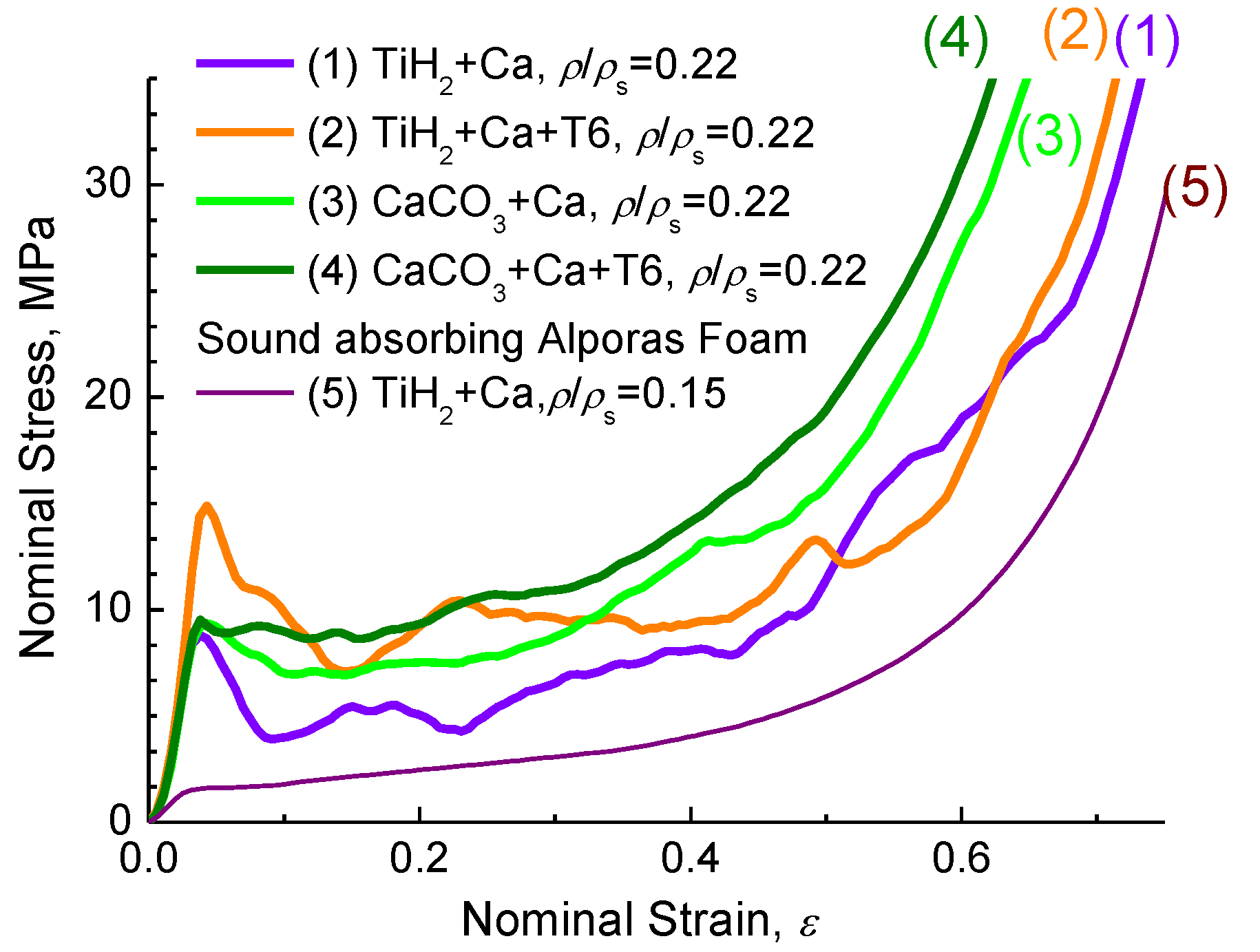
2.3. Effect of Heat Treatment on Compressive Response of Foams

Figure 5 demonstrates typical compressive stress-strain curves for different kinds of ZAM alloy foams with the same relative density, ρ/ρs = 0.22.
Figure 5. Typical compressive stress-strain curves for different kinds of ZAM 2 alloy foams (1,3) and (2,4) after heat treatment using mode T6 (see Subsection 3.2) in comparison with that of (5) Alporas foam.
Metals 04 00445 g005
The shape of the curves is typical for that demonstrated by foams of Al-alloys in which the cell wall material contains brittle constituents [4,6,8]. As a principal result, the increase of compressive strength of ZAM alloy foams after heat treatment using mode T6 (see Subsection 3.2) should be mentioned here. As it was pointed out previously [6,8], application of CaCO3 favors crucial improvement of deformation behavior for ZAM alloy foam compared to that of TiH2 foam processed in line with the original Alporas route [7]. In particular, CaCO3-foam subjected to heat treatment using mode T6 demonstrates much smoother stress-curve with no undesirable peak stress at the onset of global collapse. It is noticeable that compressive strength of sound absorbing foam based on ZAM alloys is much higher compared to that performed by the conventional Alporas route, as can be seen in Figure 5.

3. Experimental Section

3.1. Material and Processing Procedure

Two kinds of wrought AlZnMg-alloys (similar to alloy 7075) assigned here as ZAM 1 and ZAM 2 were used as matrix materials. Elementary composition, melting point, and solidus temperature of the matrix AlZnMg-alloys primary determined by DTA method are shown in Table 1.
Table 1. Elementary composition of AlZnMg matrix alloys.
CodeElement content (wt%)Temperature (K)
ZnMgCuMnCr/Sc + ZrAlliquidussolidus
ZAM 16.02.31.70.110.18/−on balance911843
ZAM 25.53.00.60.5−/<0.6on balance911843
Alternative choice of AlZnMg-alloys in experimentation was based on several aspects. First of all AlZnMg-alloys comprise great fraction volume of interdendritic network of brittle redundant phases being emerged in a matrix of α-Al solid solution [5,8]. Particularly, ZAM 1 alloy contains three redundant phases such as T(AlCuMgZn), M(AlCuMgZn), and S(CuMgAl2) whereas ZAM 2 alloy includes only T(AlCuMgZn) phase and comprises Al3(ScZr) particles randomly scattered in α-Al matrix, as shown in Figure 6. Additional difference concerns the fact that the ZAM 1 alloy tends to have pronounced interdendritic porosity, which is valuable in view of expected acoustic properties of fabricated foams.
Figure 6. SEM micrographs of different matrix AlZnMg-alloys: (a) ZAM 1 and (b) ZAM 2.
Metals 04 00445 g006

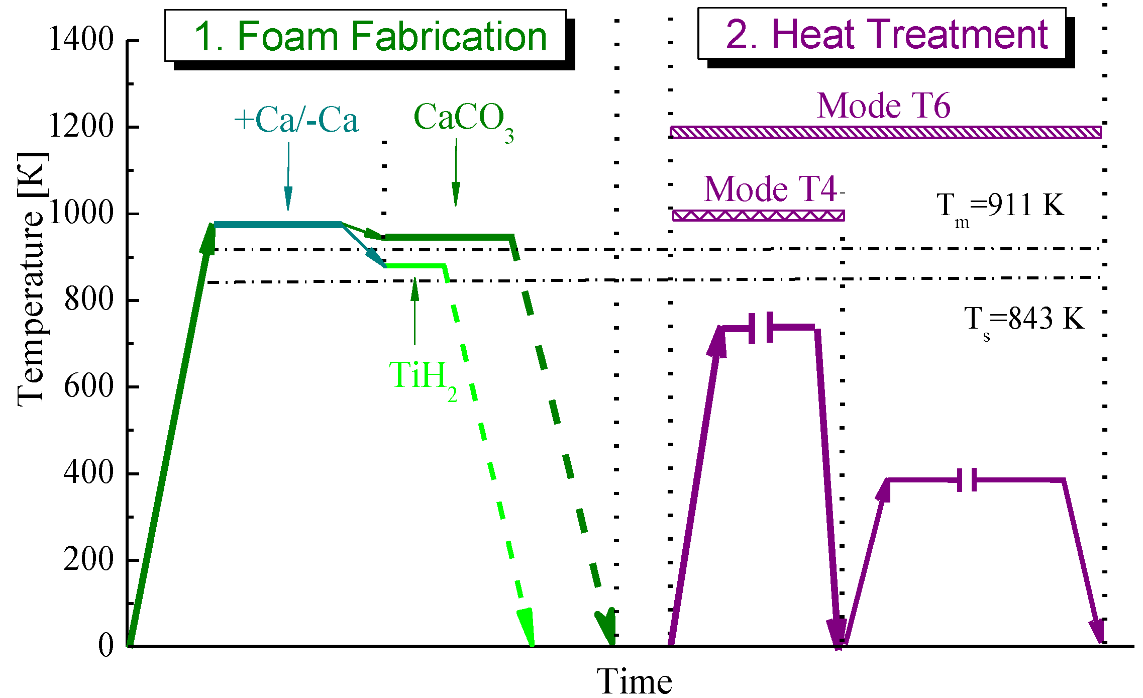
3.2. Processing Steps of Foam Fabrication

Both kinds of the AlZnMg based foams were produced via Alporas like route [7] in which either titanium hydride TiH2 (typically 1 wt%) or calcium carbonate CaCO3 (typically 2 wt%) were employed as foaming agents [5,6,8]. Temperature-time history and their processing conditions are shown in Figure 7.
Figure 7. Schematic presentation of temperature-time history of foam fabrication.
Metals 04 00445 g007
In the first step, each kind of alloy previously melted in an induction furnace was poured into a graphite crucible being placed in a resistance furnace and pre-heated to a required temperature. Following the conventional Alporas route, 1 wt% of metallic calcium was introduced as a thickening agent into a melt by vigorous stirring for 5 min in an ambient atmosphere. However, several foaming experiments were performed without Ca additive to reduce material cost. For this purpose, agitating the melt was extended up to 30 min with no Ca additive to increase an effective viscosity by nanometre-sized particles/films of oxides. Then, foaming agent was added to a melt under continued vigorous stirring. After the specified dwell-time, the crucible was removed from the furnace and the foam was allowed to solidify under cooling with fans. Attention should be drawn to the fact that the foaming temperature is roughly about 50 K higher than melting point when CaCO3 is used as foaming agent whereas it was just below melting point for the use of TiH2. Moreover, exposition time of foaming by CaCO3 was believed to be longer by several times compared to that of TiH2. This is because the CaCO3 foaming agent has a significant effect on foam stability due to oxidation of the melt by CO2 gas [5].
A basic operation of the method is the final heat treatment of solidified foamed block or cut off pieces of required dimensions. Two alternative processing modes such as T4 and T6 were employed for final heat treatment. Mode T4 included heating below the solidus temperature followed by water quenching. Mode T6 as alternative heat treatment involved processing conditions of mode T4 followed by ageing to provide enhancement of constructional strength of foam owing strengthening the cell wall material.

3.3. Structural Characterization and Testing

All of the foams were characterized structurally by their density, cell morphology and cell wall microstructure. The density was measured by weighing a sample of known volume and, then, relative density was defined by ratio ρ/ρs (where ρ and ρs correspond to the density of foam and dense solid, respectively). Porosity content was derived from the relation θ = 1 − ρ/ρs. Microstructure of the cell wall material was analyzed by scanning electron microscopy (SEM) using Jeol Superprobe-733 (JEOL, Tokyo, Japan) supplied with X-ray detectors (EDX and EPMA). TEM images and selected areas of electron diffraction (SAED) patterns were performed using JEM 2100 F (JEOL, Tokyo, Japan) microscope.
Conventional plane-wave impedance tube for normal incidence that is well documented in the literature [4,9,10] was used to study acoustic properties of the foams.
Following the method above, foamed samples of thickness about 15 mm were fitted to the tube and backed by a rigid plate during measurements done for wide range of frequencies, i.e., from 500 to 4000 Hz. By using the measurement results, absorption coefficient at normal incidence α0 was determined for each kind of the foams.
Deformation behavior of Al alloy foams was examined under uniaxial compressive tests performed on prismatic specimens with a height to thickness ratio exceeding 1.5. The minimum dimension of the specimen was seven times more than the cell size to avoid size effect. Compressive response of all kind of foams was examined under static strain rate of 1.5·10−3 s−1.

4. Conclusions

By employing AlZnMg alloys the, novel processing route for producing the sound absorbing Al-foams via an Alporas-like route with no machining operations was developed. The process includes following operational steps: (i) foaming; (ii) foam solidification; (iii) solid foam heat treatment by using either mode T4 or mode T6. Both modes comprise heating below the solidus temperature followed by water quenching, whereas mode T6 includes additional ageing to provide the enhancement of constructional strength besides improved acoustic properties. Enhanced sound absorption ability of Al-foam is provided due to opening the closed cell structure by micrometer cracks lengthways. The brittle eutectic domains are created by final heat treatment.
A number of interconnected cells rise up by reducing the relative density down to critical value, ρ/ρs ≤ 0.25, implying formation through cracks when the cell wall thickness becomes comparable with dimension of Al dendrites (roughly about 150 μm). The presence of through cracks results in global opening of the cell structure, making the cells like Helmholtz micro-perforated resonators. The latter favors greater dissipation of sound wave, ensuring the most significant increase of sound absorption coefficient at normal incidence α0 over the entire range of frequencies.
Despite the sound absorption ability of heat treated ZAM-foams performed by the cells like Helmholtz micro-perforated resonators being rather similar to that of machined Alporas foams, they differ by enhanced relative density suitable for combined constructional/functional applications. It is noticeable that the use of an inexpensive CaCO3 foaming agent gives undisputed technical advantages in the production of sound absorbing Al-foams. Besides the enhanced compressive strength, CaCO3 foams heat treated by using mode T6 demonstrate the most smooth deformation pattern with no undesirable peak stress at the onset of global collapse.

Author Contributions

The individual contribution of each co-author to the reported research and writing of the paper is as follows:
Alexandra Byakova: Experimental—processing, structural and material characterization; writing—introduction, results and discussion, conclusions.
Svyatoslav Gnyloskurenko: Experimental—part of SEM investigation; writing—introduction, experimental.
Yuriy Bezimyanniy: Experimental—sound absorption testing.
Takashi Nakamura: Experimental—part of SEM investigation; writing—general edition, conclusions.

Conflicts of Interest

The authors declare no conflict of interest.

References

  1. Nishiyama, S.; Yamaguchi, Z.; Iketani, K.; Okujima, M. Acoustic and Vibration Engineering; Corona Publishing: Tokyo, Japan, 1979; pp. 14–15. [Google Scholar]
  2. Lu, T.J.; Hess, A.; Ashby, M.F. Sound absorption in metallic foams. J. Appl. Phys. 1999, 85, 7528–7539. [Google Scholar] [CrossRef]
  3. Banhart, J. Light-metal foams history of innovation and technological challenges. Adv. Eng. Mater. 2013, 15, 82–111. [Google Scholar] [CrossRef]
  4. Ashby, M.F.; Evans, A.G.; Fleck, N.A.; Gibson, L.J. Metal Foams: A Design Guide; Butterworth-Heinemann Press: Boston, MA, USA, 2000; p. 251. [Google Scholar]
  5. Byakova, A.; Gnyloskurenko, S.; Sirko, A.; Milman, Y.; Nakamura, T. The role of foaming Agent in structure and mechanical performance of Al based foams. Mater. Trans. 2006, 47, 2131–2136. [Google Scholar] [CrossRef]
  6. Milman, Y.; Byakova, A.; Sirko, A.; Gnyloskurenko, S.; Nakamura, T. Improvement of structure and deformation behaviour of high-strength Al-Zn-Mg foams. Mater. Sci. Forum 2006, 519–521, 573–578. [Google Scholar]
  7. Akiyama, S.; Ueno, H.; Imagawa, K.; Kitahara, A.; Nagata, S.; Morimoto, K.; Nishikawa, T.; Itoh, M. Foamed Metal and Method of Producing Same. U.S. Patent 4,713,277, 15 December 1987. [Google Scholar]
  8. Byakova, A.V.; Sirko, A.I.; Mykhalenkov, K.V.; Milman, Y.; Gnyloskurenko, S.V.; Nakamura, T. Improvements in stabilisation and cellular structure of Al based foams with novel carbonate foaming agent. High Temp. Mater. Process. 2007, 26, 239–245. [Google Scholar]
  9. Kim, Y.; Hur, B.Y.; Kwon, K.C. Cellular Metals: Manufacture, Properties, Applications; Banhart, J., Fleck, N., Mortensen, A., Eds.; MIT-Verlag: Berlin, Germany, 2003; pp. 469–474. [Google Scholar]
  10. Kimura, S. Architectural Sound and Anti-noise Plan; Shokokusha Publishing: Tokyo, Japan, 1977; pp. 142–144. [Google Scholar]

