Article

Monitoring of Bainite Transformation Using in Situ Neutron Scattering

1
Department of Applied Beam Science, Graduate school of Science and Enginieering, Ibaraki University, 4-12-1 Naka-narusawa, Hitachi 316-8511, Japan
2
Graduate school of Science and Engineering, Ibaraki University, 4-12-1 Naka-narusawa, Hitachi 316-8511, Japan
3
Japan Atomic Energy Agency, 2-4 Shirane Shirakata Tokai, Ibaraki 319-1195, Japan
4
Comprehensive Research Organization for Science and Society, 162-1 Shirakata, Tokai, Ibaraki 319-1106, Japan
*
Author to whom correspondence should be addressed.
Current address: Nippon Steel & Sumikin SG Wire Co. Ltd., 7-5-1 Higashinarashino, Narashino, Chiba 275-8511, Japan.
Current address: National Institute of Materials Science, 1-2-1 Sengen, Tsukuba, Ibaraki 305-0047, Japan.
Metals 2016, 6(1), 16; https://doi.org/10.3390/met6010016
Submission received: 22 November 2015 / Revised: 22 December 2015 / Accepted: 6 January 2016 / Published: 9 January 2016
(This article belongs to the Special Issue Metals Challenged by Neutron and Synchrotron Radiation)

Abstract

:
Bainite transformation behavior was monitored using simultaneous measurements of dilatometry and small angle neutron scattering (SANS). The volume fraction of bainitic ferrite was estimated from the SANS intensity, showing good agreement with the results of the dilatometry measurements. We propose a more advanced monitoring technique combining dilatometry, SANS and neutron diffraction.

Graphical Abstract

1. Introduction

Multi-phase steels containing carbon-enriched austenite have been extensively studied because of their excellent combination of strength and ductility/toughness. To obtain multi-phase structures, various material processings have been developed such as intercritical annealing followed by quenching to produce dual-phase steels [1,2,3], isothermal holding to yield carbon-enriched retained austenite for transformation-induced plasticity (TRIP steels) [4,5], isothermal holding at a low temperature to realize ultra-fine lamellar structure (nano-bainite steel) [6,7,8,9,10], and the partial quenching followed by up-heated isothermal holding (Q&P steels) [11,12,13,14,15]. In particular, nano-bainite steels consisting of nano-scale lamellae of bainitic ferrite and carbon-enriched austenite have attractively exhibited tensile strength greater than 2 GPa and fracture toughness of approximately 30 MPa m1/2 [6,7]. The nano-bainite formed by isothermal holding at 300~400 °C shows an extremely slow transformation rate [6,16,17]. This heat treatment is favorable for producing large mechanical components with small residual stresses. However, the acceleration of the transformation must enlarge the application of nano-bainite steels. We have found that a small amount of low temperature ausforming (e.g., at 300 °C) [18,19] or partial quenching below Ms temperature [20] is effective to accelerate nano-bainite transformation. The dislocation structure introduced in austenite at low temperatures is found to assist bainite transformation with strong variant selection where partial dislocations introduced by ausforming play an important role for bainite transformation [19]. In these advanced steels, the processing is complicated enough that it is very important to monitor microstructure evolution quantitatively.
For studying microstructure evolution, in situ observations during processing using synchrotron X-ray [21,22] or neutron diffraction (ND) [19,20] have successfully been employed so far. Diffraction profiles provide the insights on volume fractions of constituents, which show good agreement with the results obtained by dilatometry [17], carbon contents in austenite [23], texture [19], and dislocation density [20]. Line broadening analysis for the ND profile provides “coherently diffracting mosaic size” probably related to dislocation cell size in engineering steels. The sizes larger than 1.0 μm such as austenite grain size or ferrite lath size cannot be evaluated by diffraction but hopefully by SANS or Bragg edge (BE) measurements. In situ BE measurement during bainite transformation was examined by Huang et al. [24]. They reported the changes in austenite volume fraction and carbon concentration with progress of bainite transformation but gave us no data on ferrite lath size. The two populations of austenite with different carbon contents have also been demonstrated by diffraction [19,22], but no information concerning the size of bainite lath has been reported so far. If we employ in situ SANS, the insights on the shape and size of the bainite lath would be obtained. In this study, we introduce a dilatometer into SANS-J-II at JRR-3/JAEA. The volume fraction of nano-bainite estimated from SANS data is compared with the results of conventional dilatometry. Then, we measure dilatometry, SANS and ND simultaneously to understand the mechanism of microstructure evolution during heat processing using an industrial neuron diffractometer, iMATERIA, at MLF/J-PARC. The traditional dilatometry provides only the phase fraction estimated from the amount of expansion or contraction of a specimen, whereas neutron experiments provide details in crystallography, chemical compositions, internal stresses, etc. This paper reports trials of such a monitoring system combined with complementary multi-methods.

2. Experimental Procedures

2.1. Specimen Preparation

The chemical compositions of the steel used in this study were 0.79C–1.98Mn–1.51Si–0.98Cr–0.24Mo–1.06Al–1.58Co–balanced Fe (mass %). The steel was prepared by vacuum induction melting [8,9]. The ingot was homogenized at 1200 °C for 14.4 ks, followed by hot-rolling in the temperature range 1200–1000 °C to reduce the thickness from 40 mm to 10 mm through 10 successive rolling passes. Plate specimens with 15 × 15 × 1 mm3 were prepared for SANS measurements at SANS-J-II (JRR-3/Japan Atomic Energy Agency, Tokai, Japan) and iMATERIA (Japan Proton Accelerator Research Complex (J-PARC), Tokai, Japan).

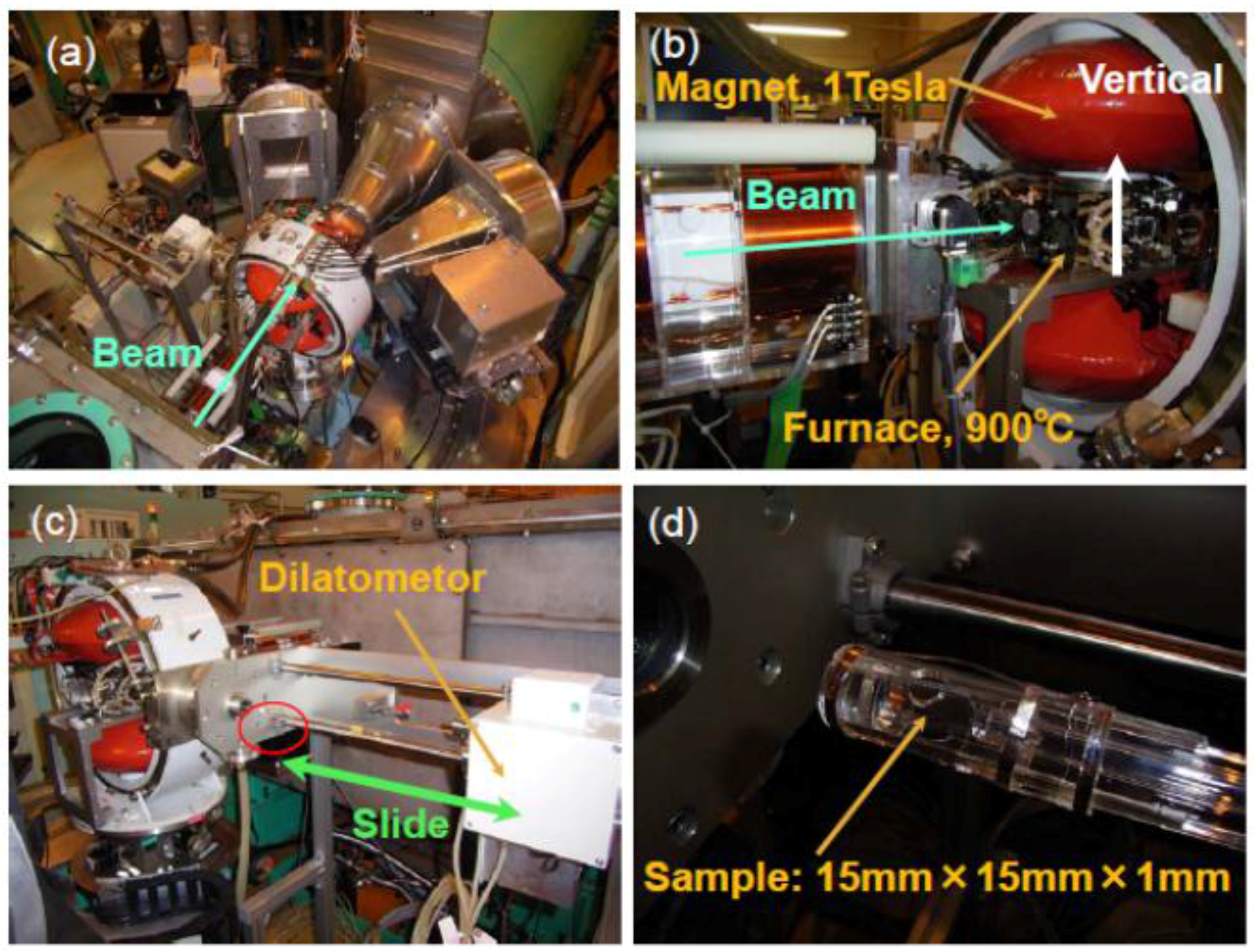
2.2. Small Angle Neutron Scattering Methods

In situ SANS measurements were performed using the SANS-J-II small angle neutron scattering instrument installed at the cold neutron beam line in the JRR-3 research reactor of the Japan Atomic Energy Agency (Tokai, Japan). For the SANS measurement, two two-dimensional (2D) detectors were used to detect neutrons scattered in the 0.005 to 0.199 nm−1 scattering vector q-range (q = (4π/λ)sinθ, where a half of scattering angle θ, and neutron wavelength λ = 0.656 nm), covering a real microstructure size of 3 to 1000 nm. The detector was positioned 10 m away from the specimen to measure the SANS profiles in the q-range of 0.005 to 0.237 nm−1. Experimental set up is shown in Figure 1. As seen, a dilatometer and a 1.0 T magnet were installed for temperature control and separation of nuclear and magnetic scattering, respectively. A thermo-couple was spot-welded on the specimen surface to control temperature of the specimen. The specimen was heated up to 900 °C with a heating speed of 2 °C/s, held there to obtain an austenite single phase microstructure for starting, and then cooled down to 300 °C with a cooling rate of 5 °C/s, followed by isothermal holding at 300 °C in vacuum under a magnetic field of 1.0 T. The time interval for data acquisition was set to be 10 min (600 s) during the isothermal holding. Using the data in the parallel direction or vertical with respect to the magnetic field direction summing azimuthal sector within 30 degrees, SANS profile, i.e., scattering intensity, was counted versus q to obtain profiles of nuclear and magnetic scattering components (for more details see Figure 3).
Concerning the iMATERIA at MLF/J-PARC, by which simultaneous measurements of dilatometry, ND and SANS were examined, the detailed explanation was omitted here because of a preliminary experiment. Brief explanation will be given in Section 3.3 together with some experimental results.
Figure 1. Experiment view of SANS with a 1 T magnet and a dilatometer to monitor the kinetics of bainite transformation at SANS-J-II/JRR-3 (JAEA): (a) overall top view; (b) magnet; (c) dilatometer and (d) specimen holder.
Metals 06 00016 g001

2.3. Data Analysis on Small Angle Neutron Scattering

The SANS intensities (I) obtained were plotted as a function of q, where lower q-values correspond to larger size of grain or particle. From the lnI(q) versus lnq plots, several microstructural parameters can be determined at different q regions, i.e., the radius of gyration (Rg) representing “the effective size of the scattering particle” can be determined by the Guinier plot in the lower q region [25,26,27,28,29].
The q-range for the Guinier approximation depends on the particle size. The particle shape can be recognized from the q-dependence of the scattering intensity, i.e., a slope of “−1” indicates cylinder shape, “−2” disc, and “−4” sphere. On the other hand, the Porod law holds in the high-q region and can be used to calculate other structural parameters. A slope of “−4” suggests that the interface of the particle is smooth and thereby the scattering intensity is proportional to the total interface area.

3. Results and Discussion

3.1. Monitoring of Bainite Transformation by Dilatometry

Figure 2 shows the temperature history of a specimen measured with a thermo-couple and the change in length obtained by dilatometry (DL). As is usually performed, the data obtained by the traditional dilatometry indicate, apparently, dilatation caused by bainite transformation at 300 °C. Though the change in specimen length can be converted to the ferrite volume fraction, i.e., kinetics of bainite transformation, the insights on chemical, crystallographic and microstructural features cannot be found. Therefore, as was described above, in situ neutron scattering/diffraction has been performed; in situ ND gave us the information on not only the change in the ferrite volume fraction but also the formation of two populations of austenite (the higher carbon concentration region and the lower one) [19,23], texture evolution [19], and dislocation density [20], as was mentioned above. Here, the size of the transformed product is expected to be monitored by SANS measurement.
Figure 2. Change in temperature and the length of a specimen (DL) during heat treatment.
Metals 06 00016 g002

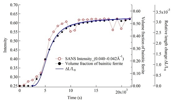
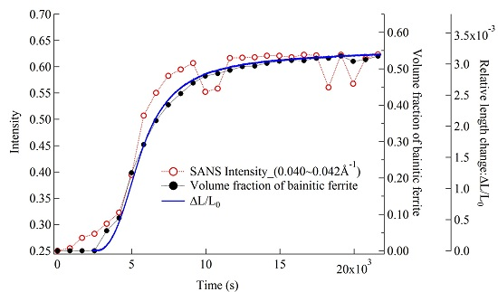
3.2. Monitoring of Bainite Transformation with in Situ SANS

Two-dimensional SANS patterns at different holding times are presented in Figure 3. It is found that the scattering intensity increases with the progress of bainite transformation both in the nuclear and magnetic components. These intensities were collected within 30° (see Figure 3c) in the parallel direction or vertical with respect to the magnetic field direction indicated in Figure 3a.
Figure 3. Change in the two-dimensional scattering pattern with holding time at 300 °C: (a) 13 min, (b) 103 min and (c) 433 min.
Metals 06 00016 g003
The nuclear component of the SANS profile obtained with a time interval of 10 min was plotted in Figure 4 as a function of the q-value. After the onset of bainite transformation, the SANS intensity of the nuclear component increased, apparently, with the holding time, i.e., progress of bainite transformation. Here, two interesting features are noticed; one is an increase in scattering intensity in a high q region, the so-called “Porod region” with a slope of −4, and the other is the slope change in a low q region, the so-called “Guinier region”. In the Porod region, the scattering intensity is proportional to the total area of the interface of scattering inhomogeneity, the bainitic ferrite lath in the present case, so that the intensity increase means the progress of transformation.
The scattering intensities at lines A and B in Figure 4 were plotted as a function of holding time in Figure 5a,b, respectively. The curves are similar to the dilatation curve shown in Figure 2 and the change in volume fraction determined by in situ neutron diffraction in the previous study [18] (the results by dilatometry, SANS and ND obtained by iMATERIA are presented together in Figure 8). As is presented in Figure 6 as an example, the morphology of bainitic ferrite lath would be assumed by a disc shape with a different radius but the same thickness. Hence, the total area of the ferrite/austenite interface is postulated to be proportional to the ferrite volume fraction. This indicates that the scattering intensity in the Porod region is proportional to the ferrite volume fraction showing the bainite transformation kinetics. Because the ferrite phase is magnetic while the austenite phase is non-magnetic at 300 °C, the magnetic scattering component also increases with the increase of the ferrite volume fraction (compare curves labeled N and N + M), suggesting that the ferrite volume fraction could be determined not only by the nuclear scattering component but also by the magnetic scattering component. This means that a magnet is not needed for the evaluation of bainite transformation.
Figure 4. Change in nuclear component of SANS profile with progress in bainite transformation.
Metals 06 00016 g004
Figure 5. SANS intensity at the Porod region as a function of holding time at 300 °C: (a) at q = 0.01 nm−1 (line A in Figure 4) and (b) q = 0.073 nm−1 (line B in Figure 4).
Metals 06 00016 g005
Figure 6. Microstructure of bainite formed at 300 °C: (a) SEM image and (b) EBSD/IPF map.
Metals 06 00016 g006
In the Guinier region, the slope of the Iq curve would be −2 (disc shape) if it appeared completely. However, the size of the bainite lath is too large to be detected in the present q-range. Hence, as was done previously for non-metallic inclusions in steels [30], we need to expand the measuring q-range to cover smaller values. The influence of multiple scattering [31] is also suspected and, hence, we cannot follow the change in the size of the bainitic lath in this experiment. From microstructure observations, it is very likely that the first lath is large in a scale of prior austenite grain size and that the later-formed laths must be shortened because the pre-formed laths inhibit further growth, although the thickness is nearly constant. Therefore, it is believed that the SANS intensity at the Porod region is proportional to the bainite volume fraction.

3.3. In Situ Measurements of Dilatometry, Small Angle Scattering and Diffraction at iMATERIA

In previous studies, we have successfully used in situ neutron diffraction to elucidate the transformation mechanism, particularly the effects of ausforming [18] and partial quenching [19]. The results in the previous Section 3.2 suggest that SANS is of use to monitor the transformation product. Hence, the combined measurements using the conventional dilatometry, ND and SANS were aimed at performing by introducing a new dilatometer into the engineering neutron diffractometer, iMATERIA at MLF/J-PARC, by which back-scatter ND and SANS can be measured simultaneously. A trial was performed using the same steel and some tentative results are presented here to show how to effectively do such an experiment.
Figure 7 shows the results of dilatometry and neutron diffraction obtained at the iMATERIA. As seen, the dilatometry result in Figure 7a is quite similar to that in Figure 2. Changes in austenite 111 and ferrite 110 diffraction profiles are presented in Figure 7b, in which the appearance of two populations of austenite with different amounts of carbon concentration found in the previous studies [19,20] is well confirmed because of the higher resolution of the back-scatter detector at the iMATERIA. The ferrite volume fraction (Vα) was calculated using Equation (1) [32,33] from the hkl diffraction intensities determined with the Z-Rietveld software (J-PARC, Tokai, Japan) [34].
V α = 1 m m I h k l α R h k l α 1 m m I h k l α R h k l α + 1 n n I h k l γ R h k l γ
where I h k l γ , I h k l α , n and m refer to the measured integrated intensities of austenite, those of ferrite, the number of ferrite peaks and those of austenite, respectively, while R h k l α and R h k l γ stand for theoretical values for texture-free material. The obtained results are plotted in Figure 7c showing a good coincidence with the dilatometry result in Figure 7a.
Figure 7. Results of preliminary in situ measurements during bainite transformation performed at iMATERIA: (a) temperature (red line) and dilatometric change (blue line); (b) changes in diffraction profile of austenite 111 and ferrite 110 peaks; and (c) volume fraction of ferrite determined from diffraction profiles.
Metals 06 00016 g007
The data analysis for SANS measurements at the iMATERIA is now in progress, so that the scattering intensity at q = 0.4–0.42 nm−1 was tentatively counted. The scattering intensity obtained was plotted in Figure 8 as a function of holding time together with the results obtained by ND and dilatometry. As can be observed, these three results are in good agreement. This was the first trial to employ SANS for monitoring bainite transformation at the iMATERIA, and, hence, the detailed analysis has not been made yet; nuclear and magnetic components were not separated because a magnetic field was not applied to the specimen in this experiment.
Three methods of neutron scattering and diffraction are applicable to monitor bainite transformation, i.e., ND, SANS and transmission BE [21] measurements. All of these methods can evaluate the transformation kinetics and have the following different possible features:
(1)
ND: crystal structure and volume fraction of constituents, texture, carbon concentration, elastic strain, and dislocation density: bulk average or three-dimensional (3D) distribution by scanning technique, although it requires scan time.
(2)
SANS: volume fraction, shape and size of the second phase: bulk average.
(3)
BE: phase volume fraction and carbon concentration of austenite, hopefully simultaneous 2D mapping of volume fraction, grain size, elastic strain and texture.
Hence, the combination of these methods would give us more fruitful information to understand microstructural evolution during processing for advanced steels.
Figure 8. SANS intensity and volume fractions of ferrite determined by neutron diffraction and dilatometry as a function of holding time at 300 °C.
Metals 06 00016 g008

4. Conclusions

Bainite transformation was monitored by in situ measurements of conventional dilatometry as well as SANS and ND. The volume fraction of bainitic ferrite was estimated from the SANS intensity in the Porod region, showing good agreement with the results obtained by dilatometry and ND. A more advanced monitoring technique combining dilatometry, SANS, ND and BE was proposed.

Acknowledgments

We would like to thank T. Ishigaki, S. Koizumi, A. Hoshikawa and K. Iwase of Ibaraki University (BL20 (iMATERIA) instrument scientists) for their help to install a dilatometer. The SANS experiments at JRR-3 was performed through the proposal #2010-A-72 and a preliminary experiment at MLF/J-PARC through proposal #2012PM0003. This study was financially supported by a Grant-in-Aid for Scientific Research A (# 21246106). The authors sincerely thank H. Beladi of Deaken University for supplying the present steel and valuable discussion during his stay at NIMS.

Author Contributions

H.N. performed this research as her master degree thesis at Ibaraki University, Y.T. coordinated this research and wrote the manuscript with help from the other authors, Y. H. and W. G. helped with experiments and data analyses, and J.S. instructed the measurement method and analysis of SANS as an instrumental scientist.

Conflicts of Interest

The authors declare no conflict of interest.

References

  1. Furukawa, T. Structure-property relationships of dual phase steels. J. Jpn. Inst. Met. 1980, 19, 439–446. [Google Scholar] [CrossRef]
  2. Tomota, Y.; Tamura, I. Strength and deformation behavior of two-ductile- phase alloys. J. Jpn. Inst. Met. 1985, 14, 657–664. [Google Scholar] [CrossRef]
  3. Tomota, Y.; Tamura, I. Mechanical Behavior of Steels Consisting of Two Ductile Phases. Trans. ISIJ 1982, 22, 665–677. [Google Scholar] [CrossRef]
  4. Matsumura, O.; Sakuma, Y.; Takechi, H. Enhancement of elongation by retained austenite in intercritical annealed 0.4C–1.5Si–0.8Mn steel. Trans. ISIJ 1987, 27, 570–579. [Google Scholar] [CrossRef]
  5. Tomota, Y.; Tokuda, H.; Adachi, Y.; Wakita, M.; Minakawa, N.; Moriai, A.; Morii, Y. Tensile Behavior of TRIP-Aided Multi-Phase Steels Studied by in situ Neutron Diffraction. Acta Mater. 2004, 52, 5737–5745. [Google Scholar] [CrossRef]
  6. Caballero, F.G.; Bhadeshia, H.K.D.H.; Mawella, J.A.; Jones, D.G.; Brown, P. Very strong low temperature bainite. Mater. Sci. Technol. 2002, 18, 279–284. [Google Scholar] [CrossRef] [Green Version]
  7. Garcia-Mateo, C.; Caballero, F.G.; Bhadeshia, H.K.D.H. Development of Hard Bainite. ISIJ Int. 2003, 43, 1238–1243. [Google Scholar] [CrossRef]
  8. Beladi, H.; Adachi, Y.; Timokhina, I.; Hodgson, P.D. Crystallographic analysis of nanobainitic steels. Scr. Mater. 2009, 60, 455–458. [Google Scholar] [CrossRef]
  9. Timokhina, I.; Beladi, H.; Xiong, X.Y.; Adachi, Y.; Hodgson, P.D. Nanoscale microstructural characterization of a nanobainitic steel. Acta Mater. 2011, 59, 5511–5522. [Google Scholar] [CrossRef]
  10. Carcia-Mateo, C.; Jimenz, J.A.; Yen, H.-W.; Miller, M.K.; Morales-Rivas, L.; Kuntz, M.; Ringer, S.P.; Yang, J.-R.; Caballero, F.G. Low temperature bainitic ferrite: Evidence of carbon super-saturation and tetragonality. Acta Mater. 2015, 91, 162–173. [Google Scholar] [CrossRef]
  11. Speer, J.G.; Streicher, A.M.; Matlock, D.K.; Rizzo, F.C.; Krauss, G. Austenite Formation and Decomposition; Damm, E.B., Merwinm, M., Eds.; TMS/ISS: Warrendale, PA, USA, 2003; pp. 502–522. [Google Scholar]
  12. Speer, J.; Matlock, D.; de Cooman, B.; Schroth, J. Carbon partitioning into austenite after martensite transformation. Acta Mater. 2003, 51, 2611–2622. [Google Scholar] [CrossRef]
  13. Edmonds, D.; He, K.; Rizzo, F.; de Cooman, B.; Matlock, D.; Speer, J. Quenching and partitioning martensite—A novel steel heat treatment. Mater. Sci. Eng. A 2006, 438, 25–34. [Google Scholar] [CrossRef]
  14. Santofimia, M.J.; Zhao, L.; Sietsma, J. Overview of mechanism involved during the quenching and partitioning process in steels. Metall. Mater. Trans. A 2011, 42A, 3620–3626. [Google Scholar] [CrossRef]
  15. Yuan, L.; Ponge, D.; Wittig, J.; Choi, P.; Jimenez, J.A.; Raabe, D. Nanoscale austenite reversion through partitioning, segregation and kinetic freezing: Example of a ductile 2 GPa Fe–Cr–C steel. Acta Mater. 2012, 60, 2790–2804. [Google Scholar] [CrossRef]
  16. Caballero, F.G.; Bhadeshia, H.K.D.H. Very Strong Bainite. Curr. Opin. Solid State Mater. Sci. 2004, 8, 251–257. [Google Scholar] [CrossRef]
  17. Koo, M.S.; Xu, P.; Suzuki, H.; Tomota, Y. Bainitic transformation behavior studied by simultaneous neutron diffraction and dilatometric measurement. Scr. Mater. 2009, 61, 797–800. [Google Scholar] [CrossRef]
  18. Gong, W.; Tomota, Y.; Koo, M.S.; Adachi, Y. Effect of ausforming on nanobainite steel. Scri. Mater. 2010, 63, 819–822. [Google Scholar] [CrossRef]
  19. Gong, W.; Tomota, Y.; Adachi, Y.; Paradowska, A.M.; Kelleher, J.F.; Zhang, S.Y. Effects of ausforming temperature on bainite transformation, microstructure and variant selection in nanobainite steel. Acta Mater. 2013, 61, 4142–4154. [Google Scholar] [CrossRef]
  20. Gong, W.; Tomota, Y.; Harjo, S.; Su, Y.H.; Aizawa, K. Effect of prior martensite on bainite transformation in nanobainite steel. Acta Mater. 2015, 85, 243–249. [Google Scholar] [CrossRef]
  21. Babu, S.S.; Specht, E.D.; David, S.A.; Karapetrova, E.; Zachack, P.; Peer, M.; Bhadeshia, H.K.D.H. In situ Observations of Lattice Parameter Fluctuations in Austenite and Transformation to Bainite. Metall. Mater. Trans. A 2005, 36A, 3281–3289. [Google Scholar] [CrossRef]
  22. Stone, H.J.; Peet, M.J.; Bhadeshia, H.K.D.H.; Withers, P.J.; Babu, S.S.; Specht, E.D. Synchrotron X-ray studies of austenite and bainitic ferrite. Proc. Roy. Soc. A 2008, 464, 1009–1027. [Google Scholar] [CrossRef]
  23. Gong, W. Transformation Kinetics and Crystallography of Nano-bainite Steel. Ph.D. Thesis, Ibaraki University, Hitachi, Japan, March 2012. [Google Scholar]
  24. Huang, J.; Vogel, S.C.; Poole, W.J.; Militzer, M.; Jacques, P. The study of low-temperature austenite decomposition in a Fe–C–Mn–Si steel using the neutron Bragg edge transmission technique. Acta Mater. 2007, 55, 2683–2691. [Google Scholar] [CrossRef]
  25. Muller, G.; Uhlemann, M.; Ulbricht, A.; Bohmert, J. Influence of hydrogen on the toughness of irradiated reactor pressure vessel steels. J. Nucl. Mater. 2006, 359, 114–121. [Google Scholar] [CrossRef]
  26. Ohnuma, M.; Suzuki, J.; Wei, F.G.; Tsuzaki, K. Direct observation of hydrogen trapped by NbC in steel using small-angle neutron scattering. Scr. Mater. 2008, 58, 142–145. [Google Scholar] [CrossRef]
  27. Buckley, C.E.; Birnbaum, H.K.; Bellmann, D.; Staron, P. Calculation of the radial distribution function of bubbles in the aluminum hydrogen system. J. Alloy. Compd. 1999, 293–295, 231–236. [Google Scholar] [CrossRef]
  28. Yasuhara, H.; Sato, K.; Toji, Y.; Ohnuma, M.; Suzuki, J.; Tomota, Y. Size Analysis of Nanometer Titanium Carbide in Steel by Using Small-Angle Neutron Scattering. Tetsu-to-Hagane 2010, 96, 545–549. [Google Scholar] [CrossRef]
  29. Su, Y.H.; Morooka, S.; Ohnuma, M.; Suzuki, J.; Tomota, Y. Quantitative Analyses on Cementite Spheroidization in Pearlite Structure by Small-Angle Neutron Scattering. Metall. Mater. Trans. A 2015, 46A, 1731–1740. [Google Scholar] [CrossRef]
  30. Oba, Y.; Koppoju, S.; Ohnuma, M.; Kinjo, Y.; Morooka, S.; Tomota, Y.; Suzuki, J.; Yamaguchi, D.; Koizumi, S.; Sato, M.; et al. Quantitative Analysis of Inclusions in Low Carbon Free Cutting Steel Using Small-Angle X-ray and Neutron Scattering. ISIJ Int. 2012, 52, 458–464. [Google Scholar] [CrossRef]
  31. Schelten, J.; Schmatz, W. Multipe-Scattering Treatment for Small Angle Scattering Problem. J. Appl. Cryst. 1980, 13, 385–390. [Google Scholar] [CrossRef]
  32. Järvinen, M. Texture Effect in X-ray Analysis of Retained Austenite in Steels. Textures Microstruct. 1996, 26–27, 93–101. [Google Scholar] [CrossRef]
  33. Gnäuperl-Herold, T.; Creuziger, A. Diffraction study of the retained austenite content in TRIP steels. Mater. Sc. Eng. A 2011, 528, 3594–3600. [Google Scholar] [CrossRef]
  34. Oishi, T.; Yonemura, M.; Morishima, T.; Oshikawa, A.; Torii, S.; Ishigaki, T.; Kamiyama, T. Application of matrix decomposition algorithms for singular matrices to Pawley method in Z-Rietveld. J. Appl. Cryst. 2012, 45, 299–308. [Google Scholar] [CrossRef]

