Article

Study on Sintering Mechanism of Stainless Steel Fiber Felts by X-ray Computed Tomography

State Key Laboratory of Porous Metal Materials, Northwest Institute for Nonferrous Metal Research, Xi’an 710016, China
*
Authors to whom correspondence should be addressed.
Metals 2016, 6(1), 18; https://doi.org/10.3390/met6010018
Submission received: 1 October 2015 / Revised: 31 December 2015 / Accepted: 4 January 2016 / Published: 13 January 2016
(This article belongs to the Special Issue Metals Challenged by Neutron and Synchrotron Radiation)

Abstract

:
The microstructure evolution of Fe-17 wt. % Cr-12 wt. % Ni-2 wt. % Mo stainless steel fiber felts during the fast sintering process was investigated by the synchrotron radiation X-ray computed tomography technique. The equation of dynamics of stable inter-fiber neck growth was established for the first time based on the geometry model of sintering joints of two fibers and Kucsynski’s two-sphere model. The specific evolutions of different kinds of sintering joints were observed in the three-dimensional images. The sintering mechanisms during sintering were proposed as plastic flow and grain boundary diffusion, the former leading to a quick growth of sintering joints.

Graphical Abstract

1. Introductions

Fe-17 wt. % Cr-12 wt. % Ni-2 wt. % Mo stainless steel fiber felts (316L SSFF) are super-light porous materials with an open net structure and a porosity ranging from 70% to 95%. They are applied to gas/liquid/solid filtration, and have recently showed great potential in the fields of impact energy absorption, fuel cell, heat transfer, etc. [1]. Typically, these materials are made by bundle-drawn 316L stainless steel fibers with diameters less than 50 μm. Two key steps are included in the manufacturing process of the materials: firstly, the fibers are mixed and sediments set to form green felts (unsintered felts) through an air-laid process, and then the green felts are sintered in vacuum at a high temperature to form metallurgical bonds between fibers. At the meso-level, the fibers distribute in a random way within the sediment layers, and the inter-fiber sintering joints bond all the fibers as a whole. The strength of the sintering joints greatly affects the mechanical property of 316L SSFF. Thus, the formation process of sintering joints is worth studying. However, the sintering mechanism of metal fiber felts has not received adequate attention. Kostomov [2] studied the relationship between sintering temperature, holding time and the macro-shrinkage of metal fiber felts and revealed that the dominant mechanism was viscous flow during the sintering of porous metal fiber felts. Using the viscous flow mode, which is initiated by surface tension, Kostomov also obtained a far higher apparent viscidity of metal fibers than that of metal powders [2]. However, since the macro-shrinkage of metal fibers is controlled not only by the formation of inter-fiber joints, Kostomov’s conclusion is doubtful. In fact, Balshin found that the elasticity energy of the metal fibers greatly enhanced the shrinkage rate of metal fiber felts during sintering [3]. Pranatis studied the sintering of parallel metal fibers using the two-sphere model of Kuczynski [4] and suggested that the dominant sintering mechanism was surface diffusion combined with volume diffusion, while under the same sintering conditions the dominant sintering mechanism of metal powders was only surface diffusion [5]. G. Matsumura studied the sintering process of parallel Fe fibers with a diameter of 200 μm and suggested that surface diffusion was the dominant sintering mechanism at 895 °C while volume diffusion was the dominant sintering mechanism at 1300 °C [6]. These studies of parallel fibers provided an analysis of the sintering mechanisms of fibers at the microcosmic level; however, they could not give a convincible explanation of the sintering mechanisms of metal fiber felts because the sintering of porous metal fiber felts is performed among the adjacent fibers with random angles in the felts. The three-dimensional (3D) structure of the sintering joints of fibers in the porous metal fiber felts is far more asymmetric than that of the sintering joints of powders with a sphere shape, so the structure evolutions of inter-fiber joints during sintering are hard to observe and study. The adjacent joints along the fibers could impact each other during the sintering process. Furthermore, the bundle-drawn 316L stainless steel fibers experience large deformation processes during the manufacturing process and contain a large density of dislocations which could affect the formation process of the sintering joints [7]. There is no ready micro-model for the sintering of inter-fiber joints. To our best knowledge, no study has been done on the sintering mechanism of 316L SSFF.
The synchrotron radiation X-ray computed tomography (SR-CT) technique is a kind of non-destructive testing technology which can realize the observation of the 3D microstructure evolution of 316L SSFF. In this study, the microstructure of 316L SSFF was reconstructed by SR-CT, and then the radii of the sintering necks and the angles between the sintered fibers were measured in the 3D image of 316L SSFF. The specific evolutions of fiber-joints during sintering were observed. Furthermore, the sintering model of inter-fiber joints was established based on the two-sphere model and the sintering mechanisms at different temperatures were analyzed.

2. Experimental Procedures

Three columns of 316L SSFF with dimension of ø1.2 mm × 2 mm, fiber diameter of 28 μm and porosity of 83% were sealed in vacuum quartz tubes with an inner diameter of 1.2 mm, respectively. All the samples were heated in vacuum drying oven at 120 °C for 0.5 h to eliminate the water vapor before being sealed in quartz tubes and the vacuum degree in the sealed quartz tubes was 10−4 Pa. Then the vacuum-sealed columns were continually CT-scanned and heated. The dislocations in the fibers may accelerate the formation of inter-fiber joints; however the dislocations may annihilate during the normal heating-up process (heating rate at 10 °C/min). Therefore, to maximize the effect of dislocations on the sintering process, a fast heating process was applied to the samples. All the samples were loaded into the muffle furnace only when the furnace had reached the preset temperature, and after certain isothermal hold the samples were withdrawn from the furnace and cooled subsequently to room temperature in air. The heating rate in this sintering process was estimated to be 300–500 °C/min. Another advantage of the fast heating process is that it can also prevent overgrowing of grains in the fibers, so it can improve the strength of fibers and in turn raise the strength of the 316L SSFF. The experimental procedure is given in Table 1:
Table 1. Specific experimental procedure.
Sintering Temperature(°C)First Holding Time (min)TestSecond Holding Time (min)TestThird Holding Time (min)Test
100010CT scan10CT scan20CT Scan
11005510
12005510
The CT scans were carried out on the BL13W1 beam line at Shanghai Synchrotron Radiation Facility (SSRF, Shanghai, China). The spatial resolution of SR-CT was 0.74 μm and the size of vision field was 1.4 mm × 1.4 mm. During the CT scan each sample spinned over 180° and 900 projection images were taken at an increment of 0.2°, each image with an exposure time of 6 s and a beam energy of 35 KeV. Then the projection images were transformed to slice images, and the 3D structure was reconstructed based on the slices. The neck radii of the sintering joints and the angles between the sintered fibers were measured in the 3D structure and the measuring process is shown in Figure 1. The black broken line in Figure 1b represents a slicing plane which is vertical to the two sintered fibers and equally divides the obtuse angle between the two fibers. This slicing plane was used to cut the sintering joint (in the red broken circle) in half to obtain a representative section of the sintering joint in the transverse direction. After the cutting, as shown in Figure 1c, the sintering joint was rotated over 90° to make the representative section envisaged and the size of inter-fiber neck radius was measured, as shown in Figure 1d.
Figure 1. Measurement of neck radius of sintering joint from the 3D structure of 316L SSFF, (a) Selection of joint, (b) Selection of slicing plane, (c) Cutting of joint, (d) Measurement of neck radius.
Metals 06 00018 g001

3. Results and Discussions

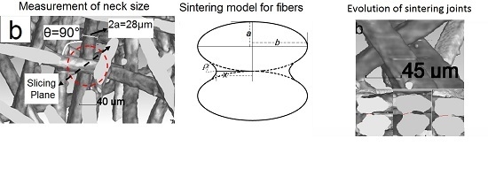
3.1. Dynamics Equation of Stable Neck Growth of Metal Fibers

The evolution of the sintering joint between two fibers is too hard to chase and characterize due to the asymmetric 3D structure; thus, a simplified two-dimensional (2D) geometry model was established to depict the evolution of the sintering joint. The key parameter to determine the shape of inter-fiber joints is the acute angle θ between the two fibers. The value of θ ranges from 0° to 90° to depict all the angle states between fibers. A plane which was vertical to the two fibers and equally divided the obtuse angle between the two fibers was selected to slice the sintering joint in half to obtain a representative section of the sintering joint in the transverse direction. The top view of the sintering joint and the transverse section of the sintering joint are shown in Figure 2, in which x represents the inter-fiber neck radius in the section and can be used as an indication of the extent of the sintering joint’s growth, and a is the radius of the fibers. When θ = 0°, the shape of the section is identical to Kuczynski’s two-sphere model. When θ ≠ 0°, the shape of the section turns into two symmetrical ellipses sintered together, as shown in Figure 2b. The 3D shape of the inter-fiber joints with θ ≠ 0° is not as symmetrical as the two-sphere model, so the curvatures of the neck surfaces in the adjacent sections of the sintering joints are different from each other and this may cause the migration of atoms between the neck surfaces in the adjacent sections. To predigest the deduction of sintering equations, it is assumed that the migration of atoms between the adjacent neck surfaces can be ignored. Through the comparison of magnitude of the migration rate of atoms between the adjacent neck surfaces at the joint with that between the neck surface and the fiber surface within one section (as shown in the Appendix), the assumption is verified. Thus, the growth of the sintering neck in the section shown in Figure 2b can be regarded as controlled only by migration of atoms within the section. Based on this model, the equations of dynamics of stable neck growth can be established in a way similar to that used by Kuczynski in the two-sphere model. According to the geometry relations in Figure 2, the value of b can be expressed as follows:
b = a / cos ( θ / 2 )
The neck surface curvature radius ρ can be expressed as follows:
ρ = x 2 ×   cos 2 ( θ / 2 ) / 2 a
The equations of dynamics of stable inter-fiber neck growth are given based on the above model as follows:
Plastic flow mechanism:
x 2 / a 2 =   4 b ω n 0 L exp ( E / k T ) t / cos 2 ( θ / 2 )
b: bergers vector; ω: coefficient of frequency; n0: volume density of atoms; E: activation energy of dislocation; L: average sliding distance of dislocations; k: Boltzmann constant; t: isothermal holding time; T: absolute sintering temperature [8].
Surface diffusion mechanism:
x 7 / a 3 =   56 D s γ δ 4 / k T cos 6 ( θ / 2 ) × t
Ds: coefficient of surface diffusion; γ: surface energy; δ: constant of crystal lattice.
Grain boundary diffusion mechanism:
x 6 / a 2 =   96 δ g D g γ δ 3 / k T cos 4 ( θ / 2 ) × t
δg: thickness of grain boundary; Dg: coefficient of grain boundary diffusion [9].
The letter n is used to depict the exponent of x in Equations (3)–(5). The certain value of n corresponds to the certain sintering mechanism. The value of n is also equivalent to the inverse slope of the ln(x/a)-ln(t) curve of inter-fiber joints and the curve can be obtained from experiments.
Figure 2. The simplified model of sintering neck of fibers; (a) Top view of sintering joint; (b) Section of sintering joint.
Metals 06 00018 g002

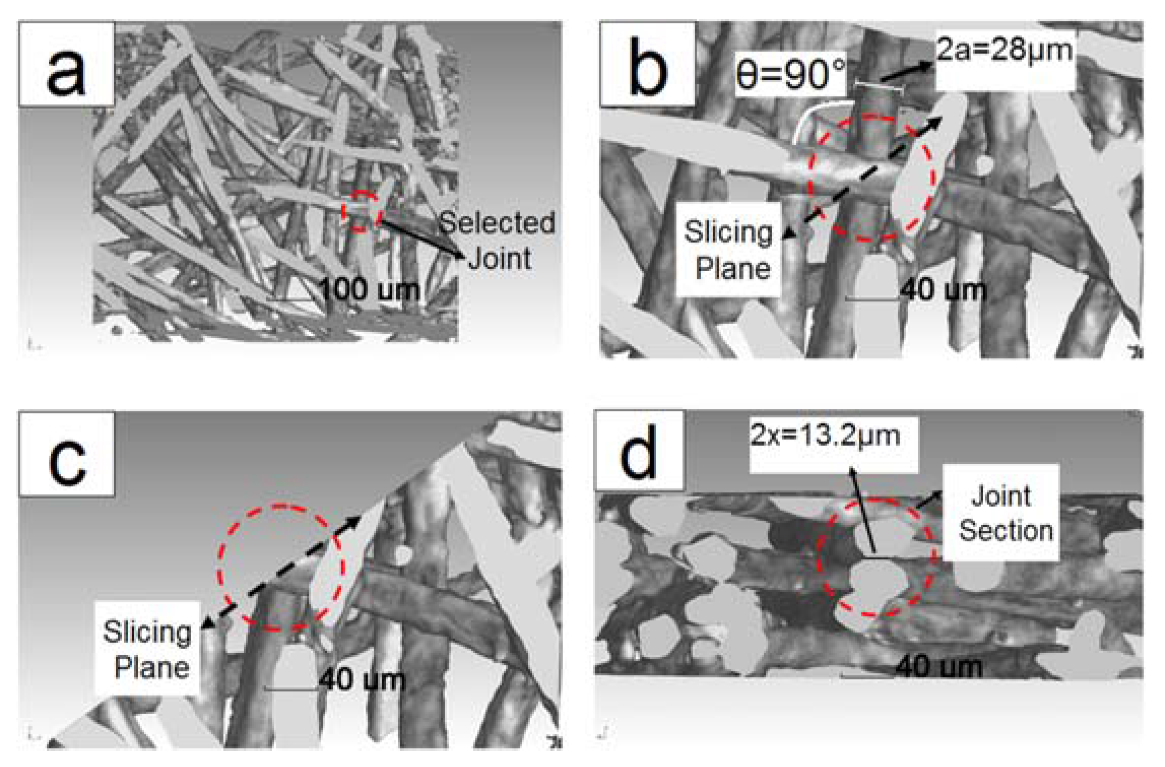
3.2. Specific Evolutions of Sintering Joints

Figure 3 shows the evolutions of four typical sintering joints holding at 1200 °C for 5 min, 10 min and 20 min. The sintering joint shown in Figure 3a had a fiber angle of 90°, and achieved a large value of neck radius when the holding time was 5 min. Its neck growth was not evident in the subsequent isothermal holding. The sintering joint shown in Figure 3b had a small initial value of neck radius when the holding time was 5 min and showed a high neck growth rate during the subsequent isothermal holding. Notably, Figure 3b also exhibits a special evolution process of sintering joints. The right-hand surface of the inter-fiber neck in Figure 3b had a higher initial curvature than the left-hand surface had, and the upper fiber approached the bottom fiber in the right-hand during the subsequent sintering process, causing the change of the relative angle between the couple fibers. It can be explained as follows: the asymmetric curvatures at the surfaces of the sintering neck could give rise to asymmetric massive transportation along the neck, eventually resulting in the angle change between the couple fibers. Detailed analysis was given by Exner [10,11]. The sintering joint shown in Figure 3c had a fiber angle of 60° and also had a small initial value of neck radius when the holding time was 5 min, and showed a high neck growth rate in the following process. An anomalous evolution process was observed in Figure 3d: the neck radius reduced at first, then a quick growth followed. A variety of mechanics could lead to this phenomenon, such as the couple fibers’ relative “rolling” caused by grain boundary sliding or the tension by adjacent sintering joints [12]. A similar phenomenon was also observed in the in-situ CT observation of microwave sintering of Al powders [13].
Figure 3. The evolutions of four sintering joints sintered at 1200 °C for 5 min, 10 min and 20 min; (a) Sintering joint of 90° experienced a slow neck growth, (b) Sintering joint of 90° experienced a fast neck growth, (c) Sintering joint of 60° experienced a fast neck growth, (d) Sintering joint of 90° experienced a anomalous evolution process.
Metals 06 00018 g003

3.3. Determination of Sintering Mechanism of 316L SSFF

The change of values of sintering neck radius x during the isothermal holding of 316L SSFF was measured in the CT images. Figure 4 presents the ln(x/a)-ln(t) curves of inter-fiber joints with a fiber angle of 90°. The values of ln(x/a) used here were the averages of 10–20 joints in each sample. According to the values of n, which was determined by the inverse slopes of ln(x/a)-ln(t) curves, the sintering mechanisms of the 316L SSFF at different temperatures could be identified.
Figure 4. The ln(x/a)-ln(t) curves of sintering joints with a fiber angle of 90° during isothermal holding at (a) 1000 °C; (b) 1100 °C; (c) 1200 °C (n = 2.33); and (d) 1200 °C (n = 6.71).
Metals 06 00018 g004
It is shown in Figure 4a,b that the values of n are close to 2 for the samples sintered at 1000 °C or 1100 °C. Thus, according to Equation (3), the dominant sintering mechanism should be plastic flow. With the sintering temperature increasing to 1200 °C, the plastic flow (n = 2.33) and the grain boundary diffusion (n = 6.71) were both observed, as shown in Figure 4c,d. It indicates that a transition of sintering mechanisms emerged around 1200 °C. At this temperature, some sintering joints had entered the later sintering stage in which the grain boundary diffusion controlled the neck growth process.
In general, the starting-up condition of plastic flow is the larger Laplace stress at the sintering neck surface rather than the critical initial shear stress of dislocation. Normally, the Laplace stress at the surface of metals is not big enough to make the dislocations slide or initiate. However, it was reported that the values of critical initial shear stress of dislocation in metals reduce quickly with the rise of heating temperature; for example, when the temperature was close to melting point, the critical initial shear stress of dislocation reduced to one-tenth of its original value [14]. Thus, it is possible that, at this high sintering temperature of 1000 °C–1200 °C, the Laplace stress at the neck surface can initiate dislocations and make them slide. Initiation of dislocations near the neck during the high temperature sintering process of metals has been reported, for example in Scatt’s investigation on the sintering between single crystal Cu powder with a diameter of 250 μm and a Cu plate, a large number of dislocations were found to initiate near the sintering neck when x/a ≈ 0.2, which was regarded as a sign of plastic flow [15]. Another supporting evidence is the phenomenon that, during holding at 1200 °C, there was a distinct transition between the plastic flow and grain boundary diffusion when the x/a reached a critical value (0.6–0.7). This can be explained as follows: the Laplace stress at the neck is inverse to the neck surface curvature radius ρ. The ρ becomes larger with the increase of the relative neck radius x/a according to the Equation (2), which leads to the decrease of the Laplace stress. When the Laplace stress decreases to a value lower than that of the critical initial shear stress of dislocation in the metal, plastic flow near the sintering neck would stop. In this case, the critical value of x/a is supposed to be 0.6–0.7. It is also worth noting that the growth of the neck radius under the plastic flow is much quicker than that under other mechanisms such as surface diffusion or grain boundary diffusion, which is beneficial to the formation of high-strength sintering-joints.

4. Conclusions

The 3D structure of 316L SSFF was reconstructed using the synchrotron radiation X-ray computed tomography (SR-CT) technique and the characteristic sizes of sintering joints were measured in the 3D structure. The equations of dynamics of stable inter-fiber neck growth were established based on the geometry model of sintering joint of fibers and Kucsynski’s two-sphere model. Two kinds of anomalous sintering processes of fiber joints were observed. The sintering mechanisms of 316L SSFF were analyzed based on the ln(x/a)-ln(t) relations of the inter-fiber joints. When sintering temperatures are relative low (1000 °C or 1100 °C), the growth of inter-fiber joints is controlled by the plastic flow which leads to a quick growth of the sintering neck. When the temperature rises to 1200 °C, the sintering mechanism changes toward grain boundary diffusion.

Acknowledgments

This work was supported by the National Nature Science Foundation of China (No. 51134003), Key Scientific and Technological Innovation Team Project of Shaanxi Province (No. 15KCT-11) and the Opening Project of State Key Laboratory of Explosion Science and Technology (Beijing Institute of Technology) (No. KFJJ15-02M).

Author Contributions

Jun Ma and Huiping Tang conceived and designed the experiments; Jun Ma performed the experiments; Jun Ma and Aijun Li analyzed the data.

Conflicts of Interest

The authors declare no conflict of interest.

Appendix

To verify the assumption that atom migration between adjacent neck surfaces in the joint can be ignored, the magnitude of the migration rate of atoms between the surfaces of adjacent necks in the joint was compared with that between the neck surface and the fiber surface within one section. Two specific sections in the joint with a fiber angle of 90° were chosen to make the calculation simplified, as shown in Figure A1. The Sections 1# and 2# are shown in Figure A1b,c and they were obtained by cutting the joint with slicing planes 1# and 2#, respectively. The direction of slicing plane 1# was the same as that of the slicing plane shown in Figure 2a, while slicing plane 2# was chosen to be vertical to the axis of the upper fiber and include the axis of the bottom fiber. The curvature of the neck surface in Section 2# is the highest of that in all the sections of the joints according to the 3D shape of the joint, consequently higher than that in Section 1#. The atom migration between the neck surfaces in Sections 1# and 2# surely exists, and it may affect the neck growth in Section 1#. To determine the extent of this effect, the atom migration rate between the neck surfaces in Sections 1# and 2# was compared to that between the neck surface and the fiber surface within Section 1#. According to the geometry relations in Sections 1# and 2#, the values of curvature of the two neck surfaces were given as follows:
1 / ρ 1 = 2 . 83 a / x 2
1 / ρ 2 = 4 a / x 2
ρ1: curvature radius of the neck surface in Section 1#; ρ2: curvature radius of the neck surface in Section 2#; a: radius of the fibers; x: radius of the necks (same value for both necks).
The vacancy concentration gradient between the two neck surfaces can be expressed as follows:
C v 1 = 4 C v ° γ Ω ( 1 / ρ 1   1 / ρ 2 ) / k T π x = 4 . 68 C v ° γ Ω a / k T π x 3
where the distance of diffusion between the two neck surfaces is πx/4;
C v 1 : vacancy concentration gradient between the two neck surfaces; Cv°: vacancy concentration at equilibrium; Ω: volume of single atom;
On the other hand, the vacancy concentration gradient between the neck surface and the fiber surface in Section 1# can be expressed as follows:
C v 2 =   8 C v ° γ Ω a 2 / k T x 4
where the distance of diffusion is ρ1;
C v 2 : vacancy concentration gradient between the neck surface and the fiber surface in Section 1#.
Noticing that x << a at the early stage of sintering, then C v 1 < < C v 2 .
The atom migration rate can be calculated based on Fick’s diffusion equation:
J = D C v
J: atom migration rate; D′: diffusion coefficient; C v : vacancy concentration gradient.
According to Equation (A5), the atom migration rate between the two neck surfaces is far smaller than that between the neck surface and the fiber surface in Section 1#. This is an analysis for the diffusions between neck surfaces of two special sections in the joint with a specific fiber angle. However, it can be generalized that the atom migration between neck surfaces in any adjacent sections of sintering joints can be ignored compared with that between the neck surface and fiber surface within one section. Thus, the growth of the neck radius in one section can be regarded as controlled only by migration of atoms within the section.
Figure A1. The sections of a sintering joint of 90° cut in different directions, (a) Directions of the two slicing planes, (b) Section 1# cut by slicing plane 1#, (c) Section 2# cut by slicing plane 2#.
Metals 06 00018 g005

References

  1. Lefebvre, L.P.; Banhart, J.; Dunand, D.C. Porous metals and metallic foams: Current status and recent developments. Adv. Eng. Mater. 2008, 10, 775–787. [Google Scholar] [CrossRef] [Green Version]
  2. Kostornov, A.G.; Galstyan, L.G. Sintering kinetics of porous fiber solids. Poroshkovaya Metall. 1984, 254, 41–45. [Google Scholar] [CrossRef]
  3. Balshin, M.Y.; Rybalchenko, M.K. Some problems of fiber metallurgy. Poroshkovaya Metall. 1964, 3, 16–22. [Google Scholar] [CrossRef]
  4. Kuczynski, G.C. Self-diffusion in sintering of metallic particles. Trans. Am. Inst. Min. Metall. Eng. 1949, 185, 169–178. [Google Scholar]
  5. Swinkels, F.B.; Ashby, M.F. A second report on sintering diagrams. Acta Metall. 1981, 29, 259–281. [Google Scholar] [CrossRef]
  6. Matsumara, G. Sintering of Iron Wires. Acta Metall. 1971, 19, 851–855. [Google Scholar] [CrossRef]
  7. Shyr, T.W.; Shie, J.W.; Huang, S.J.; Shun, T.Y.; Weng, S.H. Phase transformation of 316L stainless steel from wire to fiber. Mater. Chem. Phys. 2010, 122, 273–277. [Google Scholar] [CrossRef]
  8. Guo, S.J. Powder Sintering Theory; Metallurgical Industry Press: Beijing, China, 1998; pp. 185–187. [Google Scholar]
  9. Coble, R.L. Initial sintering of alumina and hematite. J. Am. Ceram. Soc. 1958, 41, 55–62. [Google Scholar] [CrossRef]
  10. Exner, H.E.; Bross, P. Material transport rate and stress distribution during grain boundary diffusion driven by surface tension. Acta Metall. 1979, 27, 1007–1012. [Google Scholar] [CrossRef]
  11. Exner, H.E.; Muller, C. Particle rearrangement and pore space coarsening during solid-state sintering. J. Am. Ceram. Soc. 2009, 92, 1384–1390. [Google Scholar] [CrossRef]
  12. Grupp, R.; Nothe, M.; Kieback, B.; Banhart, J. Cooperative material transport during the early stage of sintering. Nat. Commun. 2011. [Google Scholar] [CrossRef] [PubMed]
  13. Xu, F.; Li, Y.; Hu, X.; Niu, Y.; Zhao, J.; Zhang, Z. In situ investigation of metal’s microwave sintering. Mater. Lett. 2012, 67, 162–164. [Google Scholar] [CrossRef]
  14. Guo, S.J. Powder Sintering Theory; Metallurgical Industry Press: Beijing, China, 1998; p. 189. [Google Scholar]
  15. Schatt, W.; Friedrich, E.; Joensson, D. Spannungsverteilung und versetzungsvervielfachung in der sinterkontaktregion. Acta Metall. 1983, 3, 121–128. [Google Scholar] [CrossRef]

