Article

Influence of Microstructure on Strength and Ductility in Fully Pearlitic Steels

Fracture & Structural Integrity Research Group, University of Salamanca, E.P.S., Campus Viriato, Avda. Requejo 33, Zamora 49022, Spain
*
Author to whom correspondence should be addressed.
Metals 2016, 6(12), 318; https://doi.org/10.3390/met6120318
Submission received: 24 October 2016 / Revised: 29 November 2016 / Accepted: 5 December 2016 / Published: 15 December 2016

Abstract

:
This article deals with the relationship between the microstructure and both strength and ductility in eutectoid pearlitic steel. It is seen how standard mechanical properties and fracture micromechanisms are affected by heat treatment and the resulting microstructure in the material. The yield stress, the ultimate tensile strength and the ductility (measured by means of the reduction in area) exhibit a rising trend with the increasing cooling rate (associated with smaller pearlite interlamellar spacing and a lower pearlitic colony size), while the strain for maximum load shows a decreasing tendency with the afore-said rising cooling rate. With regard to the fracture surface, its appearance becomes more brittle for lower cooling rates, so that the fracture process zone exhibits a larger area with observable pearlite lamellae and a lower percentage of microvoids.

1. Introduction

Pearlitic steels exhibit an increasing yield stress with lowering interlamellar spacing in such a manner that a Hall–Petch type equation can be fitted to reproduce the relationship between microstructure and strength [1,2,3,4,5,6,7,8,9,10,11]. However, in some materials, such as cold-drawn pearlitic steel wires, the orientation of microstructure (ferrite and cementite lamellae almost fully oriented in the drawing direction) makes the classical Hall–Petch fitting not applicable, as shown in [12], and only a modified Hall–Petch relationship between yield stress and pearlite interlamellar spacing is applicable, as demonstrated in a more recent paper [13]. Mechanical resistance in pearlite is governed by events taking place in ferrite, while at the same time the cementite lamellae act as barriers against dislocational movement and limit the slip distance in ferrite [11]. On the other hand, the ductility is more dependent on the prior austenite grain (PAG) and rises for smaller grain size [14,15,16].
The higher rate of strain hardening in pearlite could be attributed to the load transfer from ferrite to cementite, with the effect of constraint created by the harder phase (cementite) on the softer one (ferrite) being significant [3]. With regard to the influence of the interlamellar spacing, steels with thin and coarse pearlite have similar strain hardening coefficients [17]. While the coarse pearlite is deformed in a non-homogeneous manner (exhibiting localized plastic strain in the form of narrow slip bands), thin pearlite shows a much more uniform strain distribution [15,17,18]. In addition, when pearlitic microstructures are considered, plastic strain generates compressive residual stresses in the ferrite and tensile stresses in the cementite, in such a manner that the level of residual stresses is higher in steels with greater interlamellar spacing [10]. When one performs standard tensile tests, the fracture micromechanisms are controlled by physical processes taking place in those colonies containing pearlite lamellae parallel to the tensile axis, where the deformation occurs in narrow bands of locally intense shear stress [11].
This paper deals with the microstructure (governed by the cooling rate), the mechanical properties (strength and ductility) and the associated fracture micromechanisms in pearlitic steels subjected to different heat treatments.

2. Experimental Method

A eutectoid steel was used (chemical composition: 0.789% C, 0.681% Mn, 0.210% Si, 0.010% P, 0.008% S, 0.003% Al, 0.218% Cr and 0.061% V). After hot-rolling the steel to produce the base material, different heat treatments were applied, consisting of heating the material in a furnace at 900 °C (above the eutectoid temperature) for 1 h and then cooling it in the fully closed furnace (FCF); in the partially opened furnace (POF); or outside the furnace, i.e., air-cooling (AC) at room temperature.
Material microstructure was analyzed by scanning electron microscopy (SEM) using a JEOL JSM-5610 LV (Jeol Ltd., Tokyo, Japan) after the metallographic preparation of small samples by mounting, grinding and polishing (up to a mirror finish) and attacking with Nital 4% (a mixture of 4 mL of nitric acid with 96 mL of ethanol) for several seconds to reveal the microstructure.
Standard tensile tests (three for each material) were performed by using cylindrical specimens of 11 mm in diameter and 300 mm in length. The crosshead speed was 2 mm/min and an extensometer with a gage length of 50 mm was placed in the central part of the samples. Finally, the fracture surfaces and longitudinal sections of the broken samples (after metallographic preparation and attack with Nital 4%) were observed through SEM.

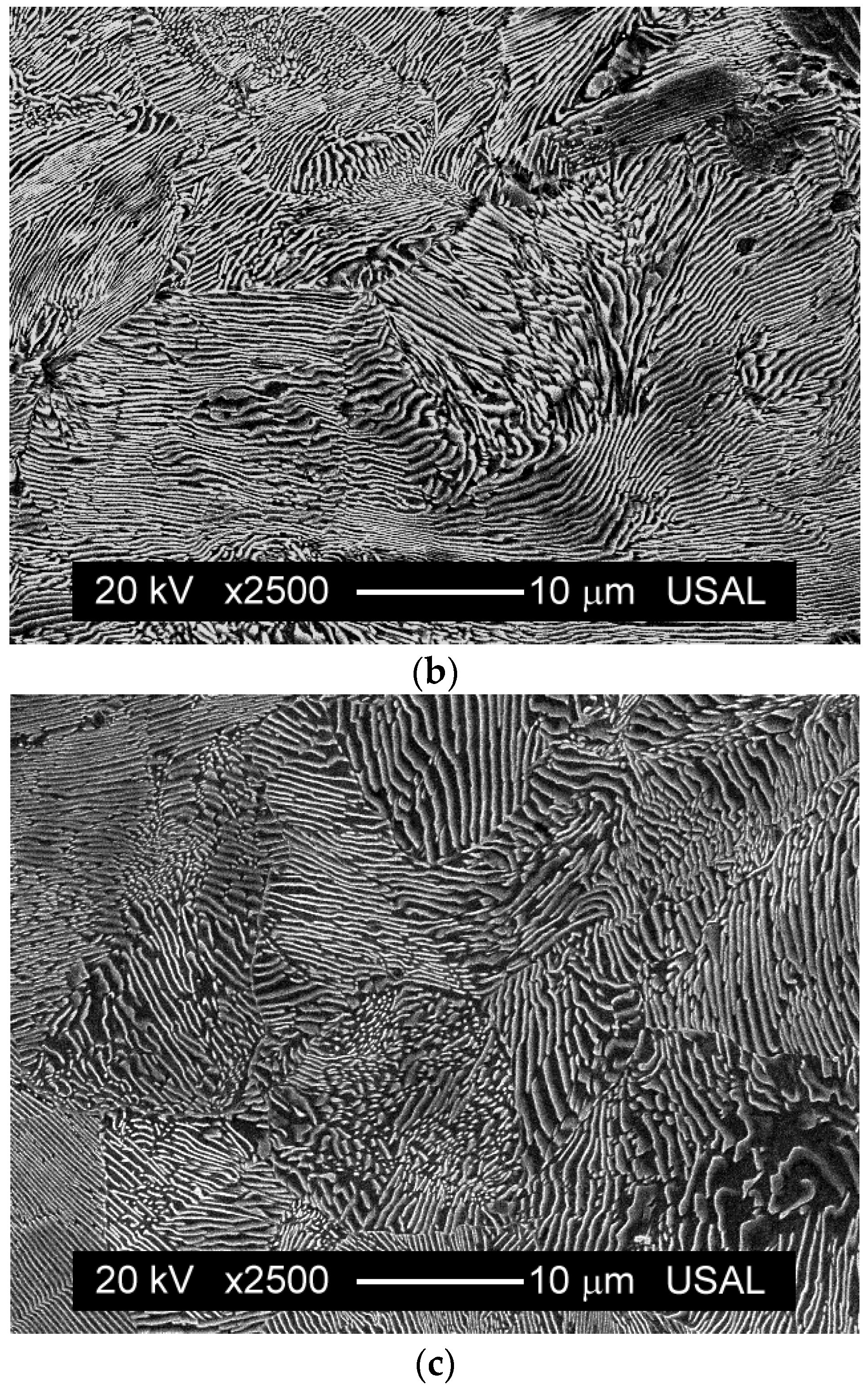
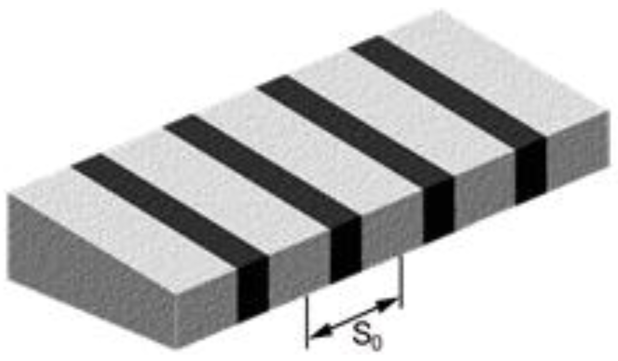
3. Microstructural Features

The different microstructures of pearlitic steels after distinct heat treatments (Figure 1) were observed by SEM (×2500). In all cases, two different microstructural levels can be defined: (i) the first microstructural level is the pearlite colony as a set of lamellae (ferrite and cementite) with a common orientation; (ii) the second microstructural level is defined by ferrite/cementite alternating lamellae.
The pearlite colony diameter dC was measured by the linear intercept method [19], consisting of the account of the number of colonies intercepted by a random straight line drawn along the micrograph, considering the randomness of both the metallographic cut and the line and using statistical methods. The interlamellar spacing of pearlite s0 (Figure 2) was calculated by the method of the circular line [20], a variant of the linear intercept method, in which a circle of known length is drawn on the photograph, and the number of intersecting pearlite lamellae is counted (also taking into account the randomness).
In the matter of continuous cooling, the transformation temperature controls the microstructure and is governed by the cooling rate. A decrease of such a rate (or, in other words, an increase of the cooling time) makes the interlamellar spacing and the size of the pearlitic colony increase (Table 1), i.e., slower cooling produces coarser microstructures.

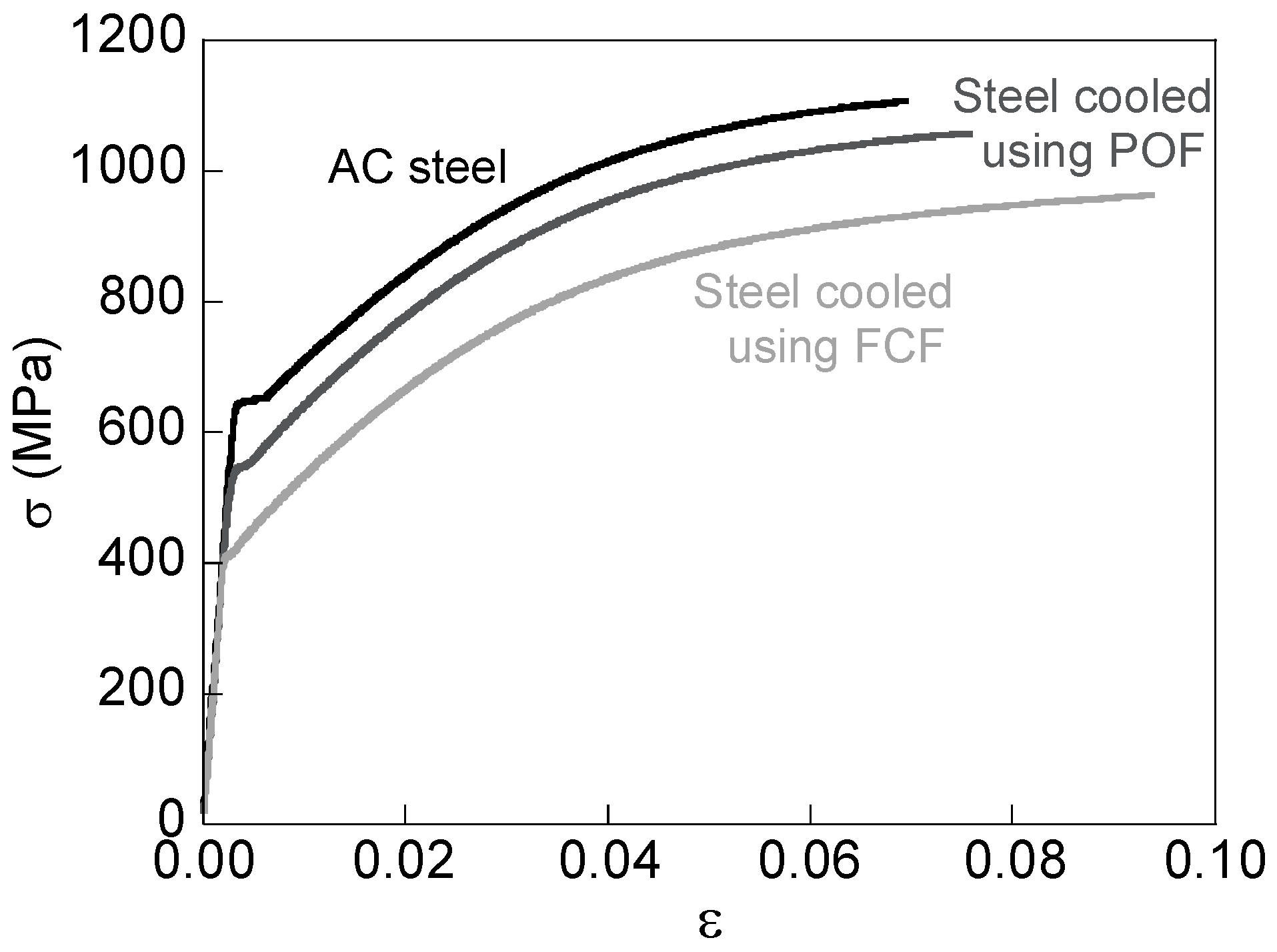
4. Mechanical Properties

On the basis of load-displacement plots after the standard tensile tests, the true stress–strain curve σ–ε characteristic of each material is obtained (Figure 3). The appearance of the three main curves (one representative of each heat treatment) indicates that a small plateau can be observed, after the linear elastic part. The size of such a plateau rises with the cooling rate applied during the heat treatment. The strain hardening portions of the curves (elastic–plastic regions) are quasi-parallel for the three analyzed steels.
Table 2 shows the mechanical properties. The three pearlitic steels produced using three different heat treatments (cooling systems: AC, POF and FCF) have the same Young modulus (E~200 GPa), but while the yield stress σY, the ultimate tensile strength (UTS) σR and the reduction in area percentage RA rise with the increase of the cooling rate, the strain at UTS εR diminishes.
In pearlitic microstructures, the yield stress is related to a critical stress necessary to shift dislocations in ferrite between two impenetrable cementite walls, in such a manner that the interfaces between ferrite and cementite act as barriers to dislocational movement [11]. Such a critical stress rises with the refinement of the pearlitic microstructure, i.e., a decrease of pearlite interlamellar spacing leads to an increase in the resistance to glide, and a Hall–Petch type relationship [1,2] with the exponent −1/2 being able to be fitted to describe the relationship between the yield stress and the interlamellar spacing. The Hall–Petch expression (with the exponent −1/2) sometimes results in an internal frictional strength of ferrite [8] with a negative value, and this is the reason why some researchers assume that an exponent −1 in the equation is more adequate [4,5,7].
With regard to the strength of the steel, in addition to the important role of the interlamellar spacing, other factors can also be influential, among them the pearlite colony size or the possible existence of a phenomenon of precipitation hardening (or precipitation strengthening) due to the alloying elements [21]. The level of the afore-said effect usually depends on the cooling strategy in certain metals, such as iron–vanadium–carbon alloys, in such a manner that, when these materials are transformed from the γ to the α state, a banded dispersion of vanadium carbide is formed. As a result, the hardening is shown to be dependent on the transformation temperature because it defines the state of the dispersion [22]. In this way, the precipitation of dispersed vanadium carbides upon pearlitic transformation of the high-carbon vanadium steel can therefore be used as a plausible procedure of precipitation strengthening of pearlite [23].
The rise of the cooling rate used during heat treatment of a given steel produces a drop of the maximum uniform elongation attained in standard tensile tests, while at the same time increasing the elongation when the necking appears (i.e., at the instant of maximum strain localization during the standard tensile test).

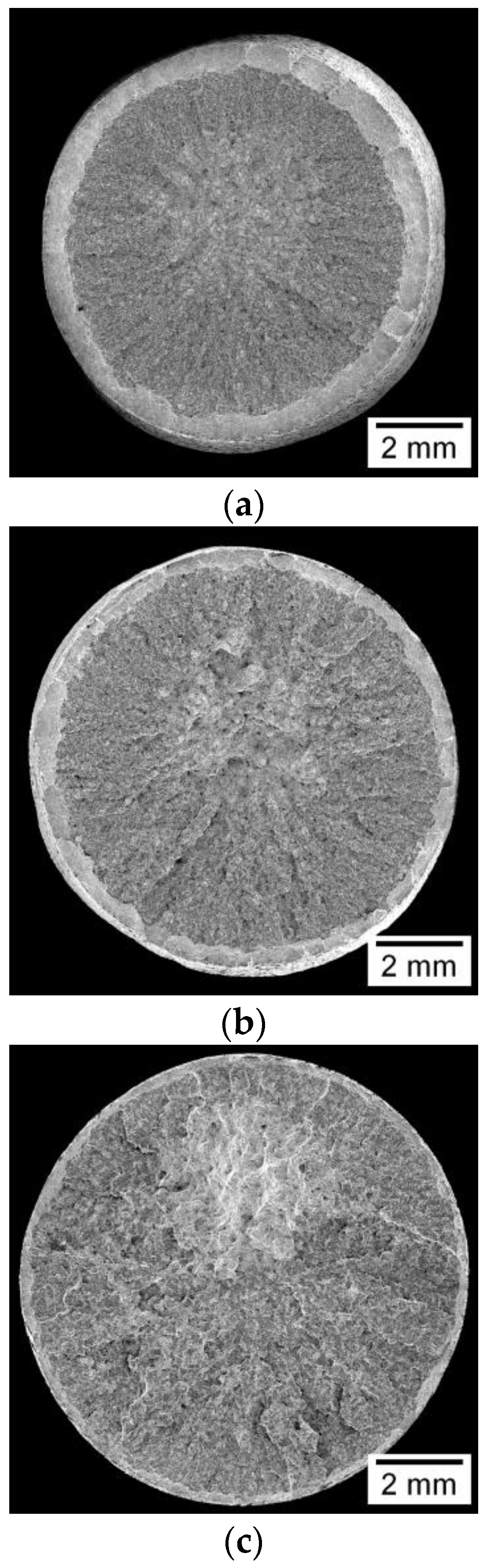
5. Fracture Surfaces

In general terms, from the macroscopic point of view, the fracture surface (Figure 4 and Figure 5) exhibits an increasingly brittle feature when the cooling rate decreases or, in other words, when the cooling time increases. In the instant of fracture, the air-cooled steel develops localized strain in the form of necking; it is a type of failure which may be classified as moderately ductile (Figure 4a and Figure 5a). On the other hand, the steel cooled in the FCF reaches the instant failure and becomes cracked without even necking, in such a manner that the fracture is more brittle and exhibits a more irregular topography (Figure 4c and Figure 5c). Finally, in the middle case consisting of the steel cooled in the partially-open furnace, the fractographic aspect can be classified as intermediate between the other two steels analyzed (Figure 4b and Figure 5b), i.e., with almost no evidence of necking.
Figure 6 shows a scheme of the different fracture regions in the steels. The origin of the failure phenomenon is an internal area in the whole fracture surface: the so-called fracture process zone (FPZ). Later, it continues by means of an unstable propagation zone (UPZ) which advances following a radial direction towards the periphery of the sample and ends at the external ring (ER) in the form of a ductile shear lip oriented 45° from the radial direction of the wire. The FPZ with fibrous appearance, situated in the central area of the wire (of a lighter color in the photographs), is many times shifted from the center of the wire. The catastrophic propagation zone (UPZ) shows radial micro-cracking, which grows more winding with increasing cooling time, while the radial thickness of the fracture area associated with the ER decreases. Generally speaking, the roughness of the whole fracture surface rises with a lowering cooling rate (Figure 4 and Figure 5). Finally, for the steel cooled inside a FCF, in some specific tests, secondary cracking also appears in a level different from that of the main fracture area (Figure 5c).
For the AC steel, the FPZ (Figure 7a) at high magnification (×2500) shows the presence of regions formed by a ductile fracture mechanism consisting of microvoid coalescence (MVC) in which the microvoids (round and elongated) present various sizes, together with small regions where pearlite lamellae are observed. In the steel cooled inside the FCF, regions formed by pearlite lamellae observed in the AC steel are now more extensive (Figure 7c), thereby indicating a more brittle fracture mode. Finally, the steel cooled inside the POF (Figure 7b) represents an intermediate case between the more ductile AC steel (Figure 7a) and the more brittle steel cooled in a FCF (Figure 7c).
In the UPZ, the fracture surface consists of mainly cleavage facets with some MVC regions among them (Figure 8), in such a manner that the typical cleavage facets (containing river patterns which mark the direction and sense of fracture propagation) are surrounded by the areas of MVC. With regard to the effect of the heat treatment duration, the lower the cooling speed the greater the size of the afore-said cleavage facets (it is seen from Figure 8a showing the smaller facets to Figure 8c with the bigger ones, Figure 8b representing an intermediate situation). The described phenomenon may be related to the size of the PAG, considering the well-known relationship between the PAG size and the extension of the cleavage facet in steels [24].
The MVC regions between the cleavage facets are most abundant in the AC steel (Figure 8a with more ductile fractography) than in steels cooled inside the furnace, either inside the POF (Figure 8b) or inside the FCF (Figure 8c with a more brittle fractography). In addition, in the latter case, the fractographic appearance consists of very large cleavage facets (at different levels) and thus MVC thin bands delimiting the boundaries of the facets.
According to previous research [5,24], the critical fracture unit in pearlitic microstructures is a region where the crystalline structure of ferrite (and cementite) of neighboring colonies shares a common orientation. The size of this orientation unit is controlled by the PAG size and, therefore, can be calculated by measuring the extension of cleavage facets appearing on the fracture surface as discussed in previous paragraphs [24].

6. Fracto-Metallographic Analysis

The fracto-metallographic analysis consists of studying both the fracture propagation path (fractographic analysis) and the internal microstructure of the material (materiallographic analysis), i.e., the aim is to evaluate the areas of damage in the middle of the ferrite/cementite lamellae inside the pearlitic colonies, so that the fracture process is seen as a consequence of material microstructure, in a sort of materials science approach.
The experimental procedure is as follows: after cutting the fractured specimens along longitudinal sections and their metallographic preparation, it is possible to observe different fracture phenomena, such as the cracking paths, the areas of localized damage, shear cracking effects, debonding or delamination zones, etc. In the particular case of the steels analyzed in this paper, in areas close to the fracture surface, it is possible to observe the micro-structural damage that the steel has suffered because of the plastic strain occurring during the standard tensile test.
In many of the colonies whose lamellae have an orientation close to the axial one of the wire (direction in which the load is applied in the standard tensile test), the existence of abundant microcracking is observed (Figure 9 and Figure 10).
In the case of colonies constituted by relatively fine pearlite (AC steel with thin interlamellar spacing and small colonies), microcracks with uneven appearance (with regard to the crack opening) and that are shorter in length than the colony size are observed (Figure 9). As a consequence, the fracture behavior in this case is more ductile because of the shortness of the afore-said microcracks acting as weak stress raisers and thus slight initiators of fracture.
On the other hand, in the case of colonies constituted by relatively coarse pearlite (steel cooled in a FCF with wider interlamellar spacing and greater colonies), the inclined cracking is generally of greater length (even across the complete colony) and looks more uniform (Figure 10). As a consequence, the fracture behavior in this case is more brittle because of the longer length of the afore-said microcracks (more or less aligned or quasi-parallel) acting as marked stress risers and thus strong fracture-initiators.
Therefore, the fracture process is determined by physical events in the pearlite colony with the lamellae being parallel to the tensile axis, where the deformation occurs in narrow bands of locally intense shear stress [11] according to the Miller–Smith mechanism [25], see Figure 11. In this phenomenon, the slip bands in the ferrite produce microcracking in the cementite plates, followed by tearing in the ferrite lamellae.

7. Conclusions

On the basis of the experimental results presented in this paper, the following conclusions may be drawn:
(1)
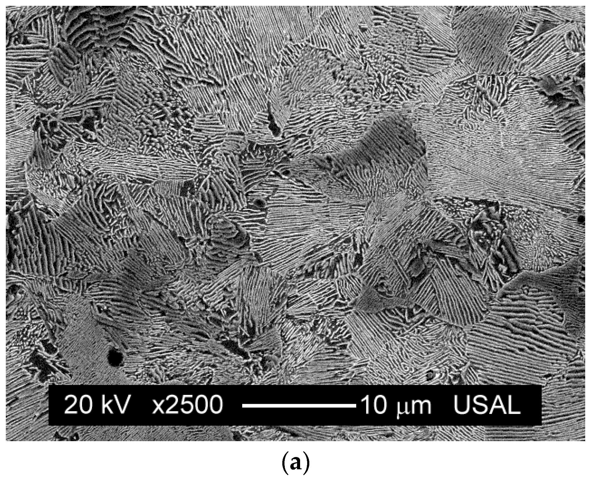
The cooling rate clearly affects the steel microstructure, so that quick cooling produces finer pearlitic microstructures (smaller colonies and lower interlamellar spacing).
(2)
Material strength (represented by the yield stress and the ultimate tensile strength) increases when the heat treatment is applied by means of a rising cooling rate.
(3)
The increase of the cooling rate produces a decrease of the strain for maximum load (uniform elongation) and an increase of the reduction in area (non-uniform elongation).
(4)
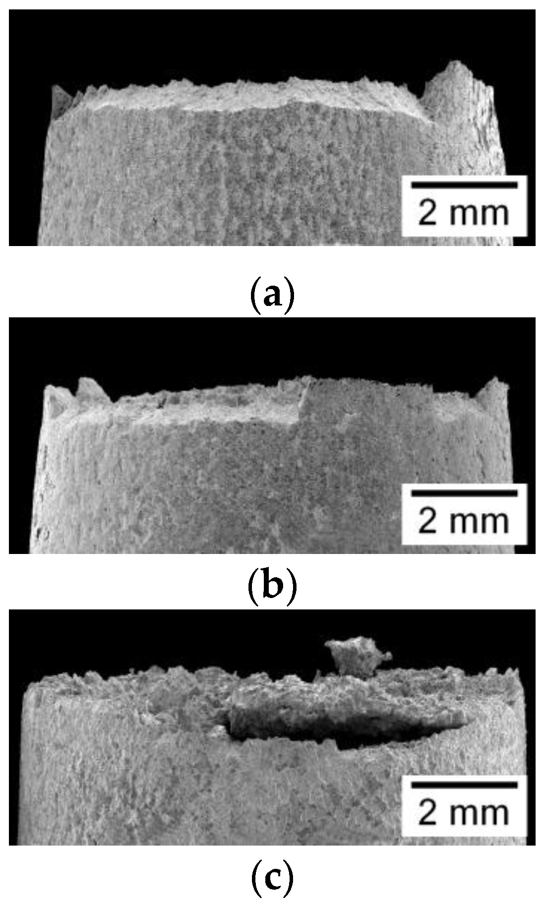
From the macroscopic point of view, fracture surfaces resemble a more ductile appearance as the cooling rate rises.
(5)
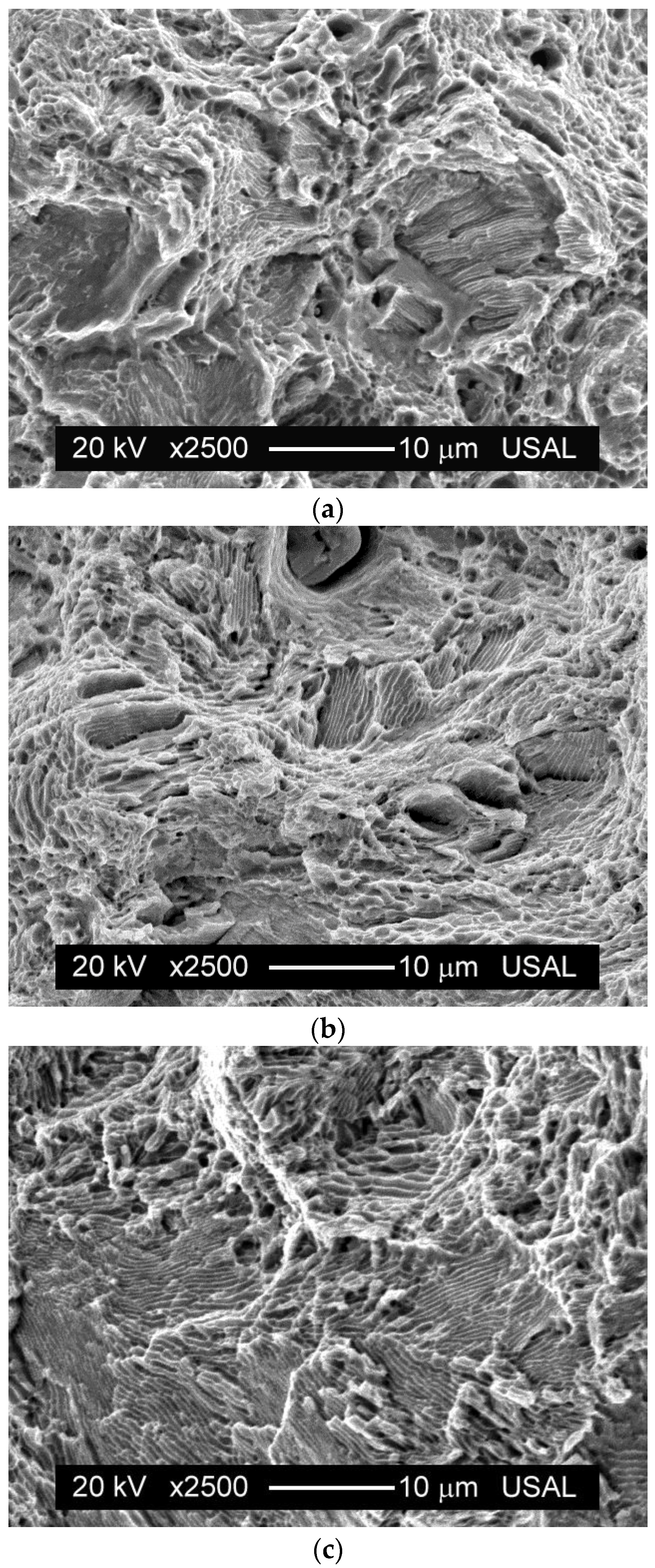
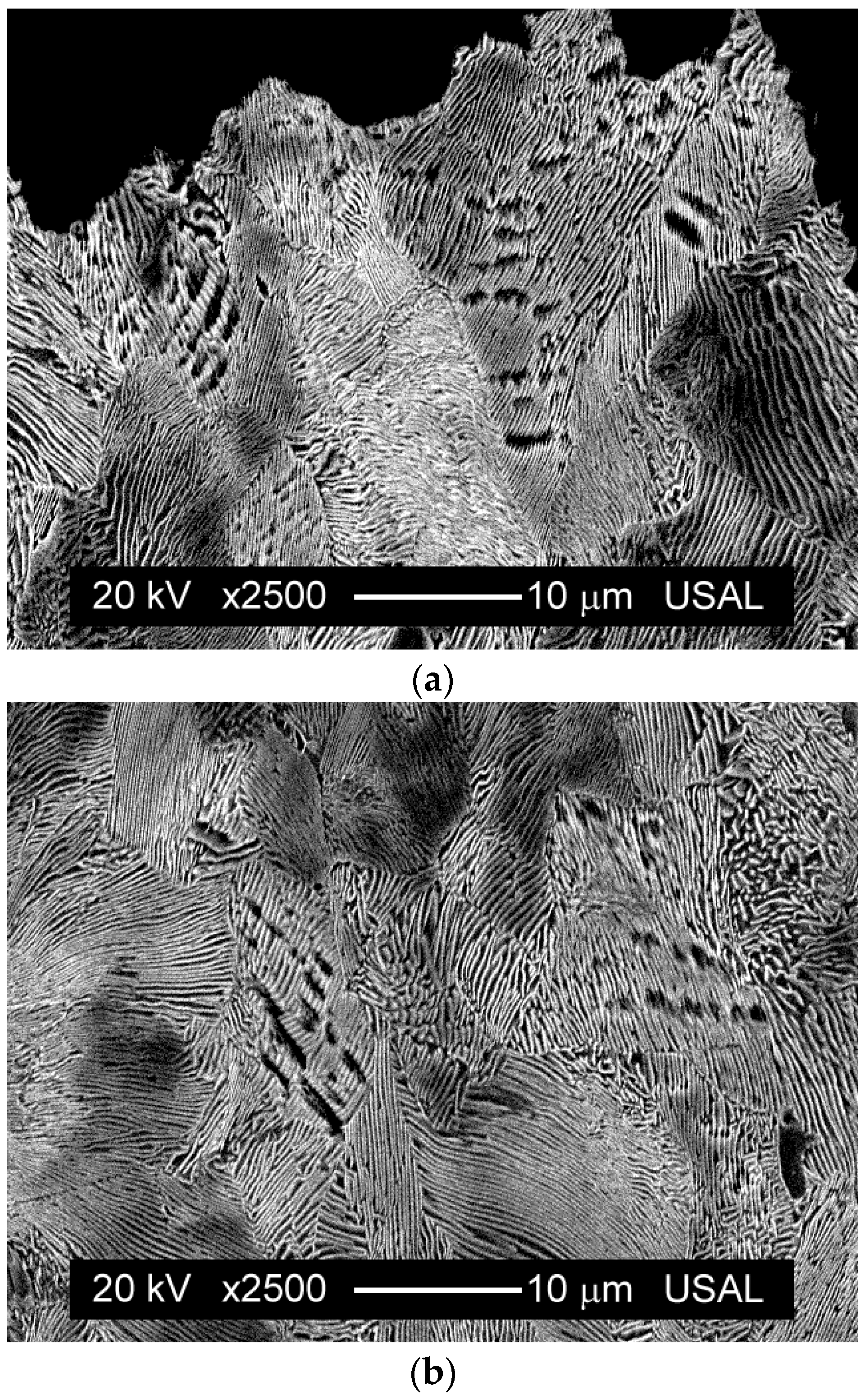
The fractography of the process zone (that associated with fracture initiation) consists mainly of a mixture of two fracture micromechanisms: microvoid coalescence (MVC) and localized areas where the pearlite lamellae are easily observed.
(6)
For coarse pearlite microstructures (those associated with slow cooling that produces bigger colonies and higher interlamellar spacing), the fracture process is more brittle and more presence of ferrite/cementite lamellae can be observed in the fracture process zone (with the associated lower percentage of MVC areas).
(7)
The macroscopic fracture mode (brittle or ductile) can be explained on the basis of the microstructure of the pearlitic steel as a consequence of the heat treatment applied on it. In fine pearlitic microstructures, micro-damage during the standard tensile test takes place in the form of very small microcracks, thereby producing a ductile fracture behavior. On the other hand, in coarse pearlitic microstructures, micro-damage happens in the form of longer and aligned microcracks, thus generating a more brittle fracture behavior.

Acknowledgments

The authors wish to acknowledge the financial support provided by the following Spanish Institutions: Ministry for Science and Technology (MICYT; Grant MAT2002-01831), Ministry for Education and Science (MEC; Grant BIA2005-08965), Ministry for Science and Innovation (MICINN; Grant BIA2008-06810), Ministry for Economy and Competitiveness (MINECO; Grant BIA2011-27870), Junta de Castilla y León (JCyL; Grants SA067A05, SA111A07 and SA039A08) and the Spanish University Foundation “Memoria de D. Samuel Solórzano Barruso” (Grant 2016/00017/001).

Author Contributions

J.T., B.G. and J.-C.M. conceived and designed the experiments; B.G., J.-C.M. and F.-J.A. performed the experiments; J.T., B.G., J.-C.M. and F.-J.A. analyzed the data; J.T. wrote the paper.

Conflicts of Interest

The authors declare no conflict of interest.

References

  1. Hall, E.O. The deformation and ageing of mild steel: III Discussion of results. Proc. Phys. Soc. Sect. 1951, B64, 747–753. [Google Scholar] [CrossRef]
  2. Petch, N.J. The cleavage strength of polycrystals. J. Iron Steel Inst. 1953, 174, 25–28. [Google Scholar]
  3. Karlsson, B.; Lindén, G. Plastic deformation of eutectoid steel with different cementite morphologies. Mater. Sci. Eng. 1975, 17, 153–164. [Google Scholar] [CrossRef]
  4. Marder, A.R.; Bramfitt, B.L. The effect of morphology on the strength of pearlite. Metall. Trans. 1976, 7A, 365–372. [Google Scholar] [CrossRef]
  5. Hyzak, J.M.; Bernstein, I.M. The role of microstructure on the strength and toughness of fully pearlitic steels. Metall. Trans. 1976, 7A, 1217–1224. [Google Scholar] [CrossRef]
  6. Kavishe, F.P.L.; Baker, T.J. Effect of prior austenite grain size and pearlite interlamellar spacing on strength and fracture toughness of a eutectoid rail steel. Mater. Sci. Technol. 1986, 2, 816–822. [Google Scholar] [CrossRef]
  7. Ray, K.K.; Mondal, D. The effect of interlamellar spacing on strength of pearlite in annealed eutectoid and hypoeutectoid plain carbon steels. Acta Metall. Mater. 1991, 39, 2201–2208. [Google Scholar] [CrossRef]
  8. Modi, O.P.; Deshmukh, N.; Mondal, D.P.; Jha, A.K.; Yegneswaran, A.H.; Khaira, H.K. Effect of interlamellar spacing on the mechanical properties of 0.65% C steel. Mater. Charact. 2001, 46, 347–352. [Google Scholar] [CrossRef]
  9. Elwazri, A.M.; Wanjara, P.; Yue, S. The effect of microstructural characteristics of pearlite on the mechanical properties of hypereutectoid steel. Mater. Sci. Eng. A 2005, 404, 91–98. [Google Scholar] [CrossRef]
  10. Yahyaoui, H.; Sidhom, H.; Braham, C.; Baczmanski, A. Effect of interlamellar spacing on the elastoplastic behavior of C70 pearlitic steel: Experimental results and self-consistent modeling. Mater. Des. 2014, 55, 888–897. [Google Scholar] [CrossRef] [Green Version]
  11. Dollar, M.; Bernstein, I.M.; Thompson, A.W. Influence of deformation substructure on flow and fracture of fully pearlitic steel. Acta Metall. 1988, 36, 311–320. [Google Scholar] [CrossRef]
  12. Toribio, J. Relationship between microstructure and strength in eutectoid steels. Mater. Sci. Eng. A 2004, 387–389, 227–230. [Google Scholar] [CrossRef]
  13. Toribio, J.; González, B.; Matos, J.C. Microstructure and mechanical properties in progressively drawn pearlitic steel. Mater. Trans. 2014, 55, 93–98. [Google Scholar] [CrossRef]
  14. Gomes, M.G.M.F.; de Almeida, L.H.; Gomes, L.C.F.C.; le May, I. Effects of microstructural parameters on the mechanical properties of eutectoid rail steels. Mater. Charact. 1997, 39, 1–14. [Google Scholar] [CrossRef]
  15. Bae, C.M.; Nam, W.J.; Lee, C.S. Effect of microstructural features on ductility in hypo-eutectoid steels. Scr. Mater. 1999, 41, 605–610. [Google Scholar] [CrossRef]
  16. Lewandowski, J.J.; Thompson, A.W. Effects of the prior austenite grain size on the ductility of fully pearlitic eutectoid steel. Metall. Trans. 1986, 17A, 461–472. [Google Scholar] [CrossRef]
  17. Izotov, V.I.; Pozdnyakov, V.A.; Luk′yanenko, E.V.; Usanova, O.Y.; Filippov, G.A. Influence of the pearlite fineness on the mechanical properties, deformation behavior, and fracture characteristics of carbon steel. Phys. Met. Metallogr. 2007, 103, 519–529. [Google Scholar] [CrossRef]
  18. Porter, D.A.; Easterling, K.E.; Smith, G.D.W. Dynamic studies of the tensile deformation and fracture of pearlite. Acta Metall. 1978, 26, 1405–1422. [Google Scholar] [CrossRef]
  19. Abrams, H. Grain size measurement by the intercept method. Metallography 1971, 4, 59–78. [Google Scholar] [CrossRef]
  20. Hu, X.; Houtte, P.V.; Liebeherr, M.; Walentek, A.; Seefeldt, M.; Vandekinderen, H. Modeling work hardening of pearlitic steels by phenomenological and Taylor-type micromechanical models. Acta Mater. 2006, 54, 1029–1040. [Google Scholar] [CrossRef]
  21. Li, J.; Sun, F.; Xu, W. On the evaluation of yield strength for microalloyed steels. Scr. Metall. Mater. 1990, 24, 1393–1398. [Google Scholar]
  22. Batte, A.D.; Honeycombe, R.W.K. Strengthening of ferrite by vanadium carbide precipitation. Met. Sci. J. 1973, 7, 160–168. [Google Scholar] [CrossRef]
  23. Izotov, B.I. Precipitation of disperse vanadium carbides at the interphase boundary upon the pearlitic transformation of a steel. Phys. Met. Metall. 2011, 111, 592–597. [Google Scholar] [CrossRef]
  24. Park, Y.J.; Bernstein, I.M. The process of crack initiation and effective grain size for cleavage fracture in pearlitic eutectoid steel. Metall. Trans. 1979, 10A, 1653–1664. [Google Scholar] [CrossRef]
  25. Miller, L.E.; Smith, G.C. Tensile fractures in carbon steels. J. Iron Steel Inst. 1970, 208, 998–1005. [Google Scholar]
Figure 1. Pearlitic microstructure in steels cooled using: (a) air-cooling at room temperature, AC; (b) partially opened furnace, POF; (c) fully closed furnace, FCF.
Metals 06 00318 g001aMetals 06 00318 g001b
Figure 2. Interlamellar spacing of pearlite.
Metals 06 00318 g002
Figure 3. Stress–strain curves (standard tensile tests).
Metals 06 00318 g003
Figure 4. Top view of the fracture surfaces in the steels cooled using: (a) AC; (b) POF; (c) FCF.
Metals 06 00318 g004
Figure 5. Side view of the fracture surfaces in the steels cooled using: (a) AC; (b) POF; (c) FCF.
Metals 06 00318 g005
Figure 6. Scheme of the different fracture regions in the steels: fracture process zone, FPZ; unstable propagation zone, UPZ; external ring, ER.
Metals 06 00318 g006
Figure 7. Fracture process zone (FPZ) in the steels cooled using: (a) AC; (b) POF; (c) FCF.
Metals 06 00318 g007
Figure 8. Unstable propagation zone (UPZ) in the steels cooled using: (a) AC; (b) POF; (c) FCF.
Metals 06 00318 g008
Figure 9. Micro-damage in AC steels: (a) in the close vicinity of the main crack; (b) below the previous area. In both micrographs, the vertical size represents the wire axis (direction of applying the load in the standard tensile test).
Metals 06 00318 g009
Figure 10. Micro-damage in steels cooled in a FCF: (a) in the close vicinity of the main crack; (b) below the previous area. In both micrographs, the vertical size represents the wire axis (direction of applying the load in the standard tensile test).
Metals 06 00318 g010
Figure 11. Miller–Smith mechanism [25].
Metals 06 00318 g011
Table 1. Microstructural parameters as a result of the cooling system.
Cooling SystemACPOFFCF
dC (μm)121519
s0 (μm)0.160.230.26
Table 2. Mechanical properties obtained by standard tensile tests.
Cooling SystemACPOFFCF
E (GPa)202200203
σY (MPa)650560441
σR (MPa)11051055965
εR0.0670.0720.092
RA (%)332014

