Article

Microscopic Analysis and Electrochemical Behavior of Fe-Based Coating Produced by Laser Cladding

1
College of Mechanical and Electrical Engineering, Central South University, Changsha 410083, China
2
National Key Laboratory of High Performance Complex Manufacturing, Central South University, Changsha 410083, China
*
Author to whom correspondence should be addressed.
Metals 2017, 7(10), 435; https://doi.org/10.3390/met7100435
Submission received: 16 September 2017 / Revised: 11 October 2017 / Accepted: 13 October 2017 / Published: 18 October 2017

Abstract

:
The effect of laser cladding on the surface microstructure and corrosion properties of coated/uncoated specimens were investigated. Fe-based alloy coating was produced on 35CrMo steel by laser cladding. The phase composition, microstructure, interface element distribution, microhardness and corrosion resistance of the cladding coating were measured. The results show that the cladding layer is mainly composed of α-Fe phases, the microstructure presents a gradient distribution, and a good metallurgical bond is formed at the boundary with the substrate. Microhardness profiles show that the average microhardness of the cladding coating is about 2.1 times higher than that of the uncoated specimen. In addition, the electrochemical results show that the coated specimen exhibits far better corrosion resistance than to the uncoated specimen.

1. Introduction

The large rotating shaft is the main bearing component of the full-swing propeller for marine dynamic positioning equipment, and works in very complicated conditions. In our previous study, we improved the overall mechanical properties of the rotary shaft by improving the casting and forging method [1]. However, considering the T-shaped geometry of the rotating shaft, the shaft was prone to failure and damage at the position where the cross section has an abrupt change.
35CrMo steel (Chinese standard) is the main manufacturing material of large rotating shafts. It is a kind of alloy structural steel widely used in industrial production, and it is often used for the manufacture of crankshaft, spindle and other important parts, owing to its low cost, high-impact toughness, static strength and higher fatigue limit [2,3].
Laser cladding is a novel surface modification method for forming dense, metallurgically bonded, high-performance coatings on metal substrates [4]. Compared to traditional surface modification technology, it has the advantages of small dilution rate, fine microstructure, high hardness and good flexibility [5]. Previous researchers have carried out many experiments and simulations to study the applications of laser cladding in diverse fields. Xu et al. established a macro model of laser cladding and a micro graphite to study the stress changes at the graphite region of grey cast iron, and the results showed that the graphite tip is a dangerous area of crack initiation, because tensile stress is concentrated there [6]. Zhang et al. investigated the microhardness and electrochemical behaviors of Cr-Ni-based stainless-steel coating to evaluate its mechanical and corrosion properties, and the results demonstrated that pitting corrosion occurs easily in enriched chloride environments [7]. Fu et al. investigated the application of laser cladding Fe-based alloy on rails and wheels, and the results indicated that the wear properties improved significantly [8]. Moreover, laser cladding technology is widely used in the remanufacture of some important parts, such as aircraft parts, railways and die [9,10,11].
However, the application of laser cladding Fe-based alloy on 35CrMo T-shaped rotating shafts working in seawater has rarely been reported. The properties of the laser cladding coating mainly depend on the properties of the cladding material and the compatibility of the cladding material with the substrate material. It is worthwhile investigating the surface properties of 35CrMo steel after laser cladding processing.
In the present study, characteristics of the coatings including the phases composition, microstructure, element distribution, and microhardness were investigated. Furthermore, electrochemical impedance spectroscopy and polarization curve were measured to compare the corrosion resistance of the Fe-based coating and the uncoated substrate. This study will verify the application of the cladding system of 35CrMo steel Fe-based alloy on a rotating shaft.

2. Materials and Methods

2.1. Materials

Two kinds of materials were used in the experiment, 35CrMo steel and cladding powder.
The substrate material was cut from a 35CrMo round steel with dimensions of Φ 90 × 15 mm. The main chemical composition of 35CrMo steel included (in wt %): 0.36C, 0.30Si, 0.61Mn, 0.98Cr, 0.19Mo, 0.012Ni, 0.014P, 0.0062S, and the remainder Fe. The substrate was processed by the standard heat treatment, in accordance with the specifications of heat treatment for 35CrMo steel.
The powder used in the laser cladding was a novel Fe-based alloy (WEL LC3558) with a particle size distribution of 45–180 μm (−45/212 sieve size), and its chemical composition was as follows (in wt %): 0.14C, 14.55Cr, 0.19Mo, 1.24Ni, 0.93Si, 1.22B, and the remainder Fe.

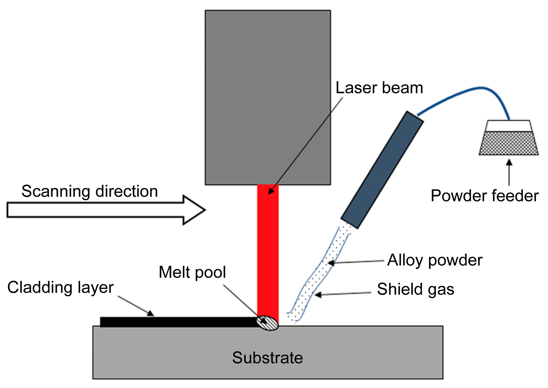
2.2. Laser Cladding Processing

Prior to the laser cladding experiment, the surface of the substrate was mechanically ground with sandpaper, and then cleaned with acetone to remove any pollution. The roughness (Ra) of the substrate after the grinding process was about 1.6–3.2 μm. The alloy powder was dried to ensure its good fluidity.
The laser cladding experiment on 35CrMo steel was carried out with a TFL-H6000 transverse flow CO2 laser device (Tongfa, Shenzhen, China) at a wavelength of 10.6 μm. A circular laser spot was obtained on the surface of the substrate when the laser is focused. The motion of the laser head relative to the substrate was achieved by a five axis NC machine tool. By the means of a powder feeder, the alloy powder was sent to the molten pool on the surface of the 35CrMo steel together with the protective gas. Argon was applied to deliver alloy powder and prevent the molten pool from being oxidized. The schematic diagram of laser cladding processing is shown in Figure 1, and the processing parameters used in the laser cladding experiment are given in Table 1. The roughness (Ra) of the coated sample after laser cladding is very high, so we used a grinding machine to smooth the coating surface, following which the roughness (Ra) was about 0.8–1.2 μm.

2.3. Microscopic Analysis

The phase composition of the cladding coating was measured by an X-ray diffraction (XRD, D8 Advance, Bruker, Billerica, MA, USA) with Cu Kα radiation. The detected range of the diffraction angle 2θ was from 20° to 100° in steps of 0.02°.
The coated specimens were ground and polished, then etched with aqua regia for several minutes. An optical microscope (OM, OLYMPUS DSX500, Tokyo, Japan) and scanning electron microscopy (SEM, EVO MA10, ZEISS, Jena, Germany) were utilized to observe its cross-section microstructure. After the SEM observation, the element distribution at the interface of cladding layer and substrate was characterized using an Energy Dispersive Spectrometer (EDS, Oxford Instruments, Abingdon, UK).
The microhardness at the cross-section of the coated specimens was tested from surface to substrate by a micro-hardness tester (HVS-1000, Huayin, Laizhou, China). The load was 200 g and the duration was 15 s. The minimum distance between adjacent points is about 0.2 mm for accurately measuring the change of microhardness.

2.4. Electrochemical Studies

The electrochemical behavior of the coated and uncoated specimens at room temperature in 3.5% NaCl solution was analyzed by potentiodynamic polarization curve and electrochemical impedance spectroscopy (EIS) using an electrochemical workstation. The test temperature was 25 °C and the pH was about 8.
Electrochemical measurements were performed using a conventional three-electrode electrochemical system [12,13]. Among them, the saturated calomel electrode (SCE) and platinum sheet were used as the reference electrode and auxiliary electrode, respectively. Specimens with area of 1 cm2 were used as the working electrode. The samples were immersed in the corrosion medium for 15 min before the electrochemical test. The rate of the potentiodynamic sweep was 1 mV∙s−1. The sweep range of potential was from −1.6 V to 0.4 V. At the EIS testing, the initial potential was set as the corrosion potential in polarization tests, and the frequency range of scanning was from 0.1 to 100,000 Hz.

3. Results and Discussion

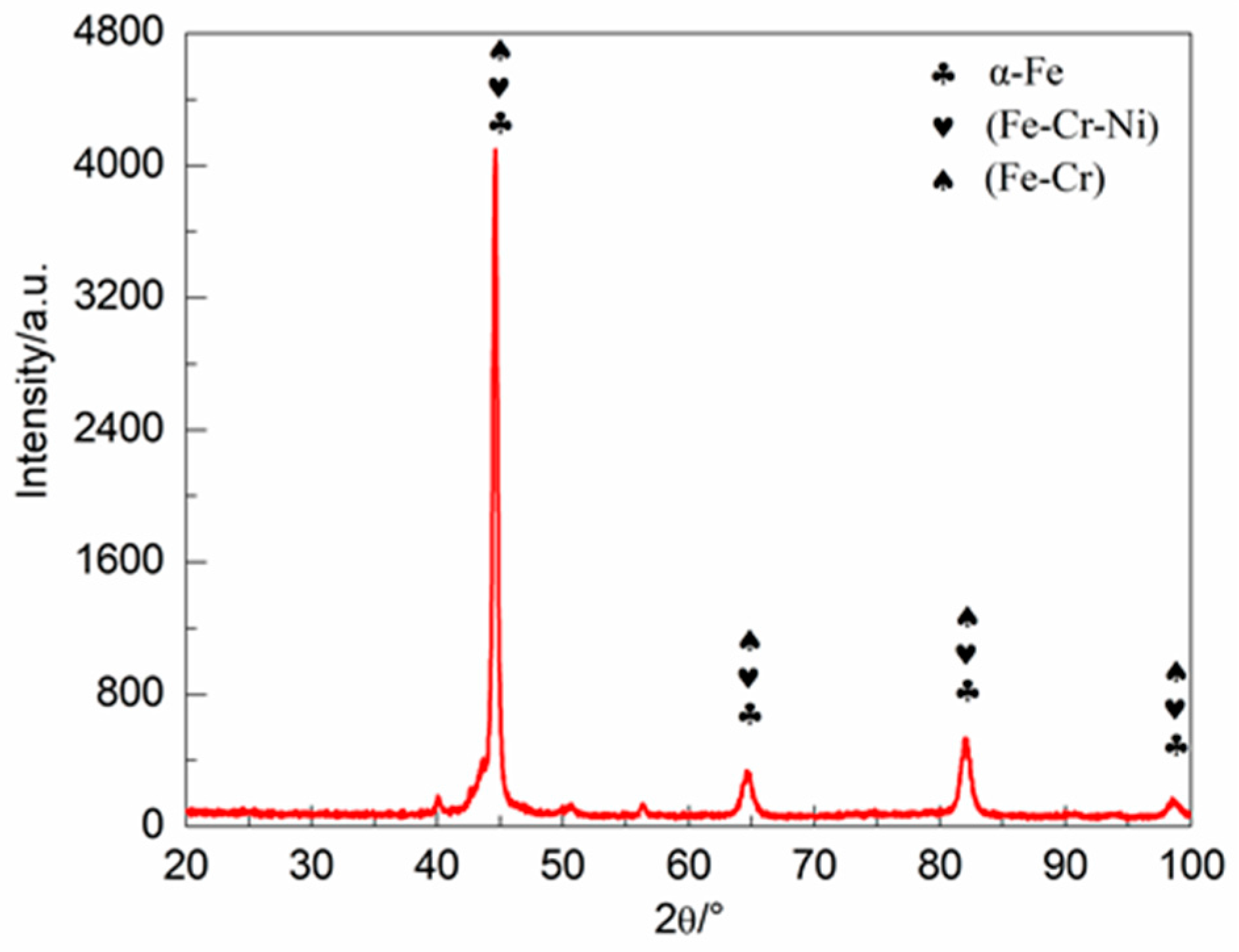
3.1. Phase Composition
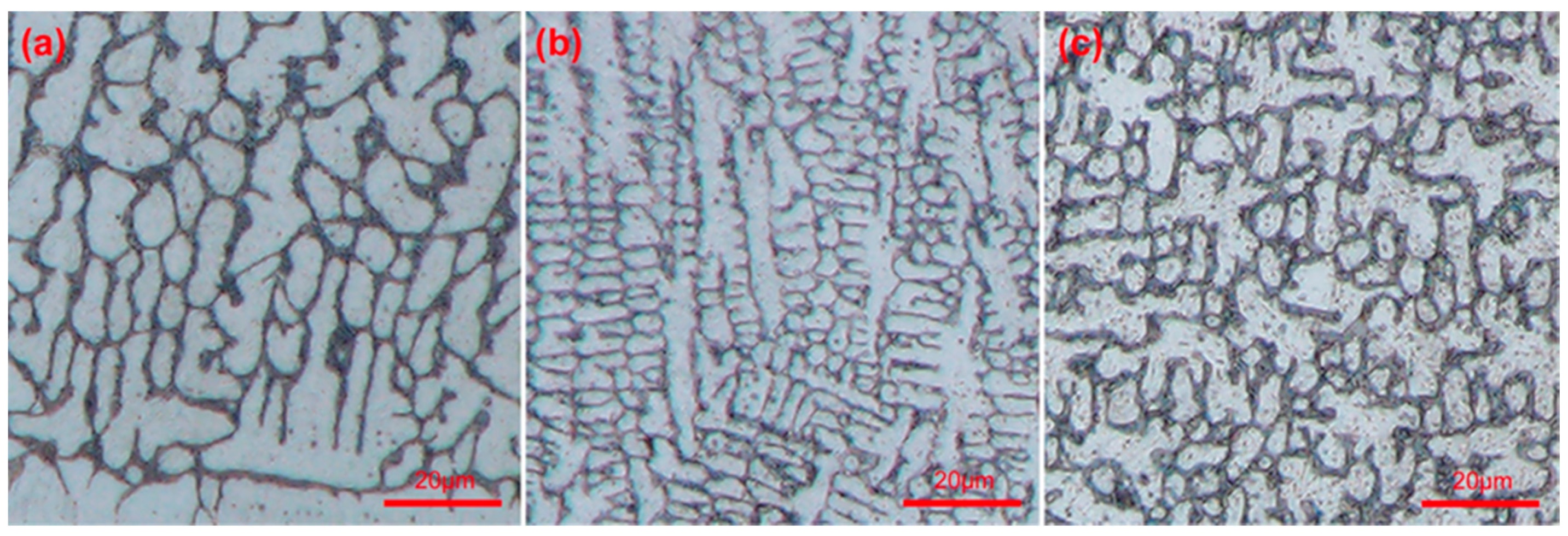
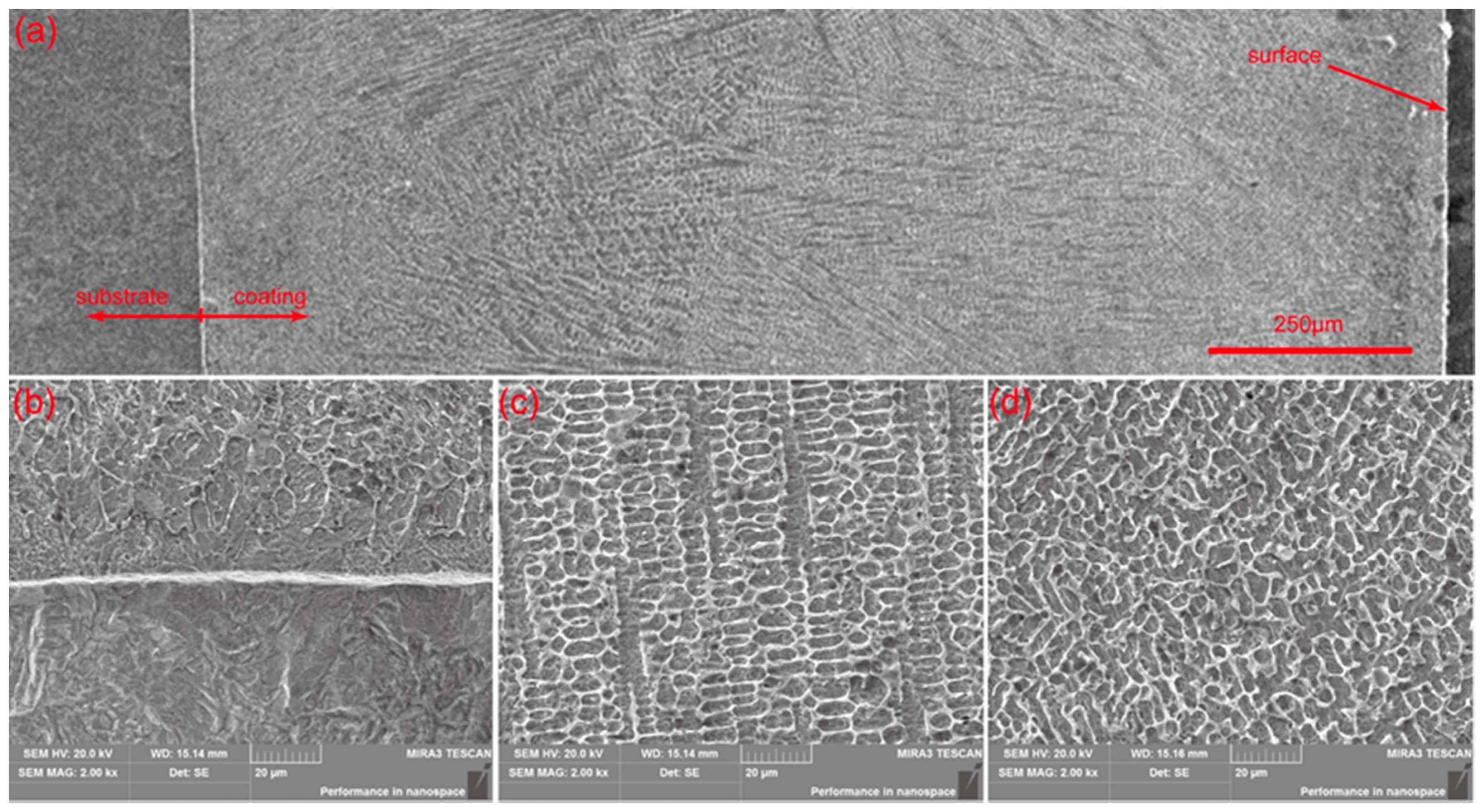
The X-ray diffraction pattern of the Fe-based coating is presented in Figure 2. According to the X-ray diffraction peaks, it could be found that the cladding coating might consist of α-Fe, (Fe-Cr) and (Fe-Cr-Ni). The solubility of Cr in Fe is 100%, and the solubility of Ni in Fe is 10% at room temperature. Cr and Ni will replace Fe atoms in α-Fe to form substitutional solid solutions. Because Cr and Fe could form infinite solid solution, as well as the fact that the content of Ni is small, it could be concluded that the coating mainly consists of α-Fe phases, including Fe and the solid solution of Fe with Cr and Ni.

3.2. Microstructure

The cross-section microstructures of the laser cladding specimen under OM and SEM are presented in Figure 3 and Figure 4, respectively. Figure 4a shows the cross-sectional view of the laser cladding specimen. It can be found that there were no pores, cracks or other defects in the cladding coating. Figure 3a–c and Figure 4b–d display the microstructure of the bottom, middle, and upper regions of the cladding coating, respectively. The SEM micrographs show a similar dendritic structure to that of OM. Obviously, the cladding coating exhibits a gradient distribution in depth. The bright bounding interface region in Figure 4b is an indication of metallurgical bonding, suggesting excellent bonding strength between coating and substrate.
The gradient morphology change of the cladding coating microstructure is due to the difference of G/R ratio at different positions during solidification, where G represents the temperature gradient and R represents the solidification rate [14]. At the beginning of solidification, the G/R ratio near the interface is very high, resulting in the growth of columnar dendrites (in Figure 3a and Figure 4b). With the solidification front moving to the surface, the G/R ratio decreases. Thus, equiaxed dendrite growth occurs, resulting in an equiaxed dendritic morphology at the upper region of coating (in Figure 3c and Figure 4d).

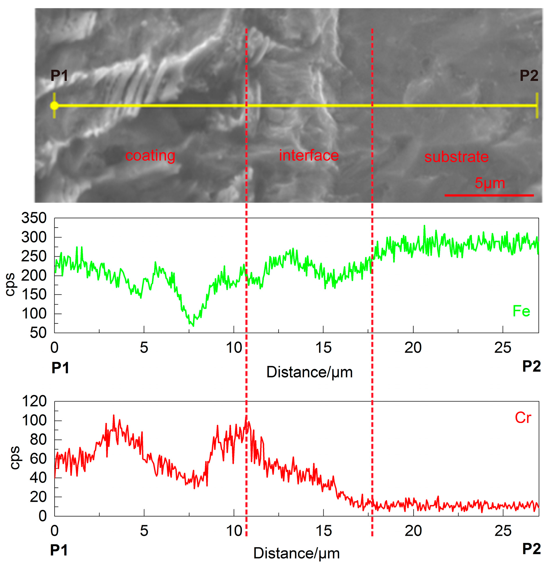
3.3. Energy Dispersive Spectrometer (EDS) Line Analysis
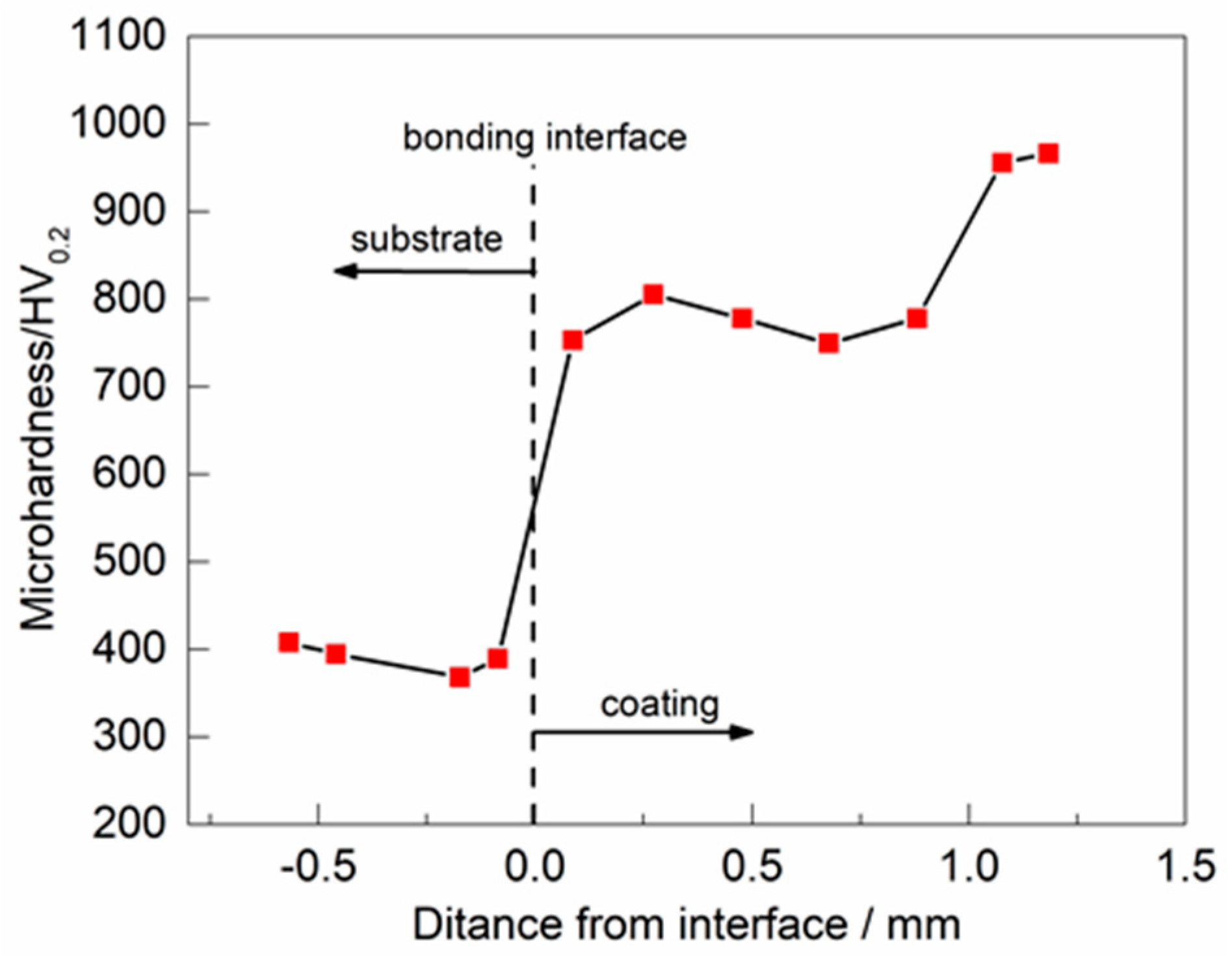
The results of elemental analysis of EDS line scanning at the bounding interface region between the laser cladding coating and the 35CrMo substrate are presented in Figure 5. For the accuracy of results, Fe and Cr—elements with higher content—were selected as the object of analysis. According to the results of line element analysis from P1 to P2, the compositional changes of the elements Fe and Cr are very obvious. The element Cr increased from the substrate to the coating, while the element Fe was the opposite. The diffusion of the various elements in the interface region can be attributed to the dilution of the 35CrMo substrate and Fe-based alloy powder in the melt pool, which contributes to the metallurgical bonding between the coating and the substrate [15].

3.4. Microhardness

The microhardness measured at the cross section along the depth of the laser cladding sample is illustrated in Figure 6. From the microhardness profiles, it could be found that the microhardness of the laser cladding specimen presents a gradient change, and a sharp change occurs at the bounding interface of the cladding coating and the substrate. The average microhardness of the coating is 826 HV0.2, which is about 2.1 times higher than that of the substrate (385 HV0.2). The increase in microhardness could be attributed to the finer and denser microstructure and the strengthening effect of solid solution phases. Microhardness is an important indicator of the mechanical properties of materials [16]. The tendency of the microhardness in the results corresponds to the aforementioned microstructure.

3.5. Electrochemical Analysis

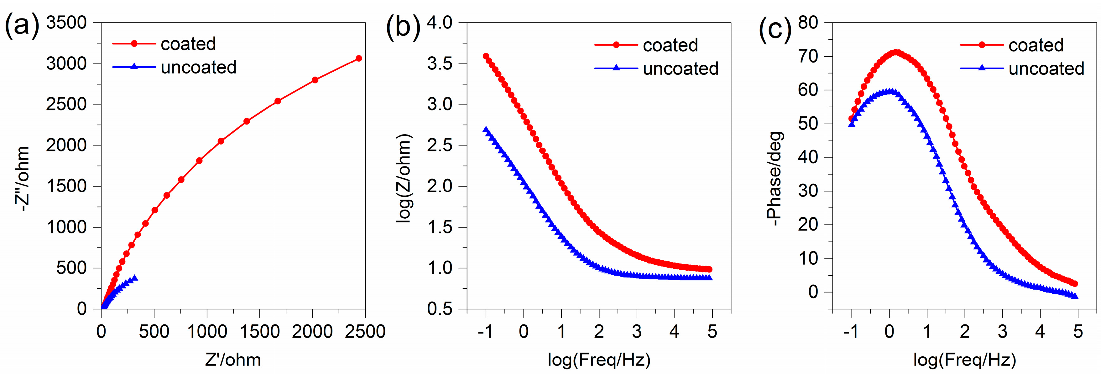
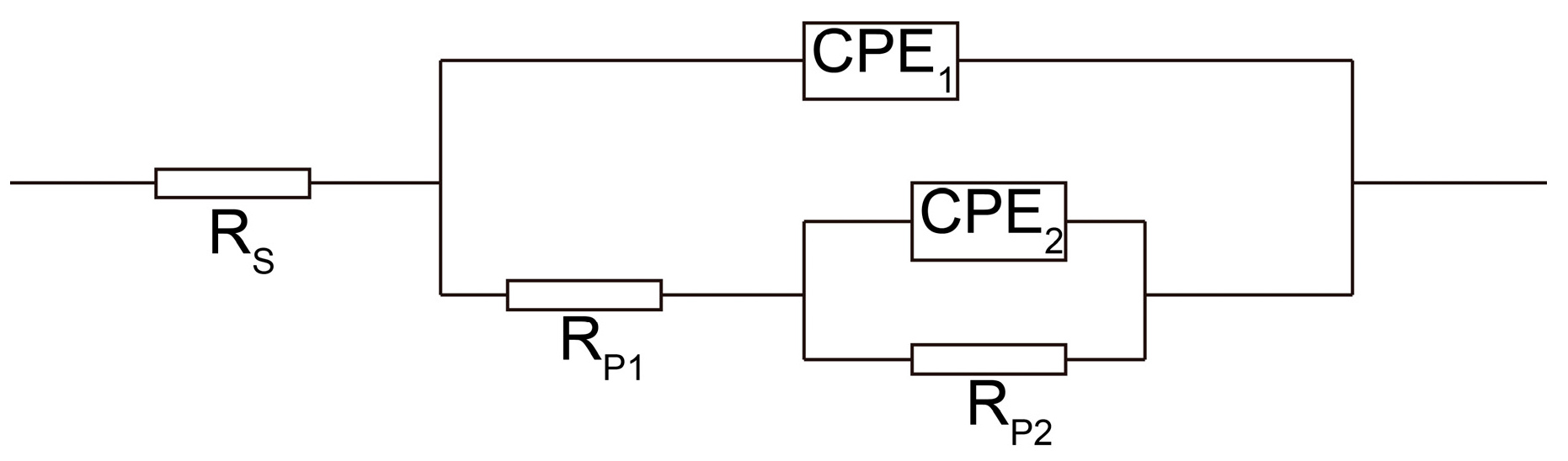
3.5.1. Electrochemical Impedance Spectroscopy

The corrosion behavior of coated and uncoated 35CrMo specimens in 3.5% NaCl solution was studied by electrochemical impedance spectroscopy (EIS). The Nyquist curve of the cladding coating and the 35CrMo substrate are shown in Figure 7a. The Nyquist curves of the uncoated 35CrMo steel and the Fe-based cladding coating show similar semicircular shapes, while the semicircular diameter of uncoated 35CrMo substrate is significantly smaller than that of the coated specimen. The semicircular diameter reflects the corrosion performance of the materials, and they are positively related [17]. Thus, the Nyquist curves indicated that the corrosion performance of the coated specimen was significantly improved compared with the uncoated 35CrMo substrate. Figure 7b,c represents the Bode diagram of the uncoated and coated 35CrMo specimens. It can be seen from Figure 7b that the impedance of the Fe-based coated specimen is ~3.6 Ω, much larger than that of uncoated 35CrMo steel substrate ~2.7 Ω. The results show that the formation of the protective film on the cladding layer leads to its having a better corrosion resistance. The maximum phase in Figure 7c resulted from the formation of the protective film, and the maximum phases of the cladding layer and substrate are 71° and 60°, respectively. This shows that the corrosion rate of the Fe-based coated specimen is lower than that of the uncoated substrate.
The equivalent circuit shown in Figure 8 was applied to fit the data. Rs is the solution resistance, CPE is the constant-phase elements, Rp = Rp1 + Rp2 expresses corrosion resistance. CPE contains two parameters, one is Y, another is n, a dimensionless exponent. The fitting results are described in Table 2. It was found that the corrosion resistance Rp of the coated specimen was much larger than uncoated 35CrMo substrate, and it was confirmed that the corrosion resistance of the coated specimen had improved.

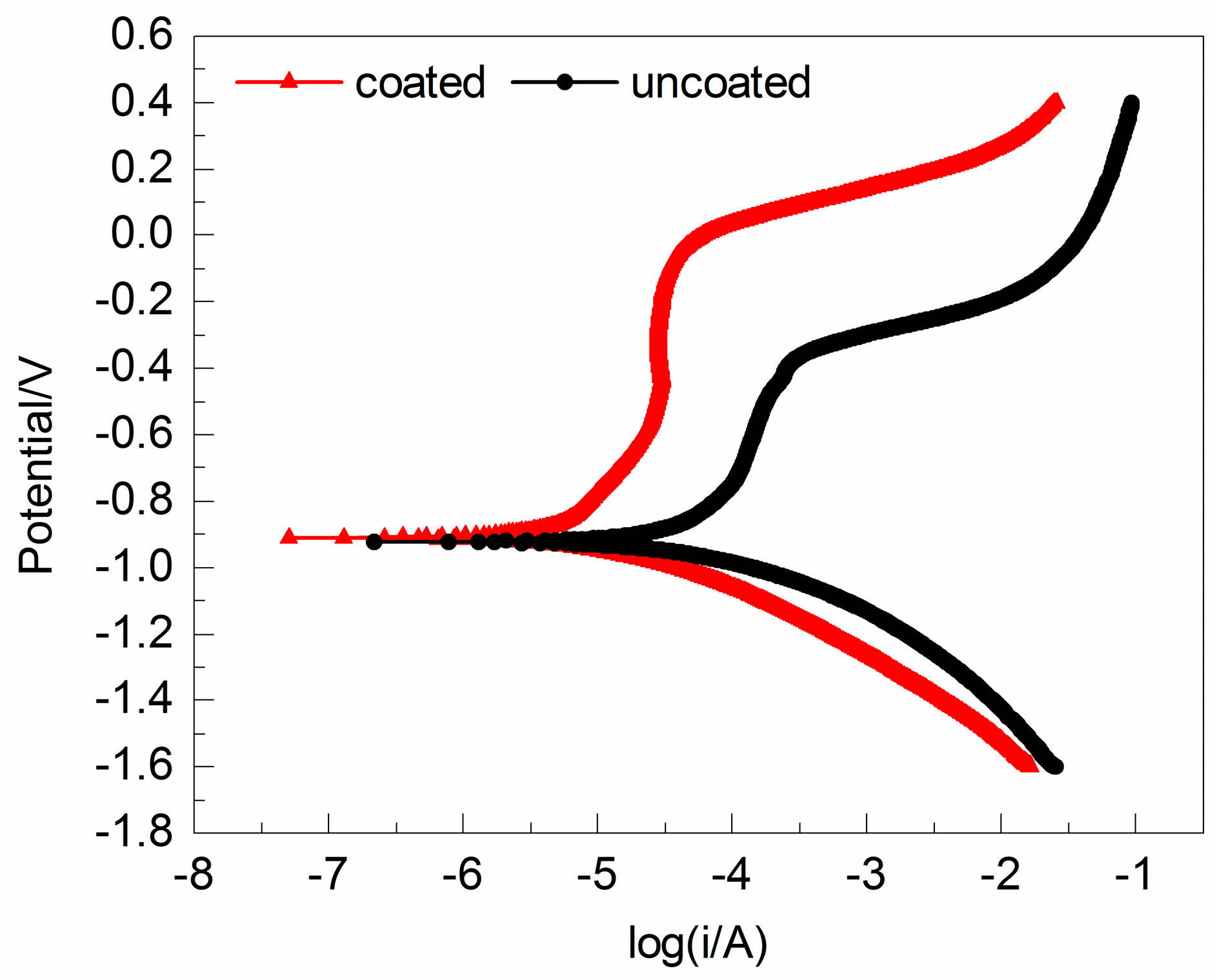
3.5.2. Potentiodynamic Polarization Curve

The potentiodynamic polarization curves of the coated and uncoated specimens in 3.5% NaCl solution were displayed in Figure 9. Potentiodynamic polarization parameters measured by the extrapolation of the Tafel curve are listed in Table 3. It can be seen from Figure 9 that the cathodic polarization of the coated specimen displays an obvious passivation phenomenon. With a corrosion potential from −0.6 to −0.1 V, the corrosion current changes very slowly. Then, the cathodic polarization of the uncoated 35CrMo steel substrate has no obvious passivation phenomenon. It could be seen from the calculation results shown in Table 3 that the corrosion potential of the laser cladding specimen (Ecorr) for −0.910 V is slightly higher than that of the uncoated 35CrMo substrate. Meanwhile, it can be concluded that the corrosion resistance of coated specimen is improved by about 4.6 times compared with that of the uncoated 35CrMo substrate. The polarization resistance (Rp) is significantly higher than that of the uncoated 35CrMo substrate.
The better corrosion resistance of the coated sample may be attributed to the high content of the Cr element, which could contribute to the formation of passive film [18,19] on the coating surface, and the corrosion current is reduced remarkably, thus improving its corrosion resistance. Moreover, the dense and fine microstructure of the coating also resulted in a better corrosion resistance.

4. Conclusions

The microstructure and electrochemical corrosion resistance of laser cladding Fe-based coating were studied in this paper. The results show that the Fe-based coating is suitable for the surface modification of 35CrMo rotating shafts working in a seawater environment. From the microscopic analysis, the following results could be summarized. The coating mainly consists of α-Fe phases, including Fe and the solid solution of Fe with Cr and Ni. A fine and dense microstructure was obtained in the laser cladding coating. The diffusion of the various elements contributes to metallurgical bonding between the 35CrMo steel substrate and the coating. The microhardness of the cladding coating is 826 HV0.2, which is much better than that of the substrate (325 HV0.2). Based on the electrochemical analysis, it was found that the coated specimen had a better corrosion resistance than the uncoated 35CrMo substrate. In order to further explore the effect of laser cladding on the service life of large rotating shafts, fatigue properties of laser cladding specimens will become the next study focus.

Acknowledgments

The authors would like to acknowledge the financial assistance provided by Major State Basic Research Development Program of China (No. 2014CB046702).

Author Contributions

Jinlin Chen and Yajun Zhou conceived of and designed the experiments; Jinlin Chen carried out the experiments; Jinlin Chen, Yajun Zhou and Chen Shi analyzed the data; Daheng Mao contributed reagents, materials, and analysis tools; and Jinlin Chen wrote the paper.

Conflicts of Interest

The authors declare no conflict of interest.

References

  1. Liang, G.; Shi, C.; Zhou, Y.; Mao, D. Effect of Ultrasonic Treatment on the Solidification Microstructure of Die-Cast 35CrMo Steel. Metals 2016, 6, 260. [Google Scholar] [CrossRef]
  2. Zhang, J.W.; Lu, L.T.; Shiozawa, K.; Zhou, W.N.; Zhang, W.H. Effect of nitrocarburizing and post-oxidation on fatigue behavior of 35CrMo alloy steel in very high cycle fatigue regime. Int. J. Fatigue 2011, 33, 880–886. [Google Scholar] [CrossRef]
  3. Zhang, J.; Xue, Q.; Li, S.; Qin, Z. Microstructure, corrosion and tribological properties of Ti(CN) multilayer coatings on 35CrMo steel by CVD. Rare Met. 2014, 1–7. [Google Scholar] [CrossRef]
  4. Liu, H.; Hao, J.; Han, Z.; Yu, G.; He, X.; Yang, H. Microstructural evolution and bonding characteristic in multi-layer laser cladding of NiCoCr alloy on compacted graphite cast iron. J. Mater. Process. Technol. 2016, 232, 153–164. [Google Scholar] [CrossRef]
  5. Xu, G.; Kutsuna, M.; Liu, Z.; Yamada, K. Comparison between diode laser and TIG cladding of Co-based alloys on the SUS403 stainless steel. Surf. Coat. Technol. 2006, 201, 1138–1144. [Google Scholar] [CrossRef]
  6. Xu, P.Y.; Liu, Y.C.; Yi, P.; Fan, C.F.; Li, C.K. Research on variation and stress status of graphite in laser cladding process of grey cast iron. Mater. Sci. Technol.-Lond. 2014, 30, 1728–1734. [Google Scholar] [CrossRef]
  7. Zhang, P.; Liu, Z. Physical-mechanical and electrochemical corrosion behaviors of additively manufactured Cr-Ni-based stainless steel formed by laser cladding. Mater. Des. 2016, 100, 254–262. [Google Scholar] [CrossRef]
  8. Fu, Z.K.; Ding, H.H.; Wang, W.J.; Liu, Q.Y.; Guo, J.; Zhu, M.H. Investigation on microstructure and wear characteristic of laser cladding Fe-based alloy on wheel/rail materials. Wear 2015, 330–331, 592–599. [Google Scholar] [CrossRef]
  9. Liu, Q.; Janardhana, M.; Hinton, B.; Brandt, M.; Sharp, K. Laser cladding as a potential repair technology for damaged aircraft components. Int. J. Struct. Integr. 2011, 3, 314–331. [Google Scholar] [CrossRef]
  10. Sun, S.D.; Leary, M.; Liu, Q.; Brandt, M. Evaluation of microstructure and fatigue properties in laser cladding repair of ultrahigh strength AerMet® 100 steel. J. Laser Appl. 2015, 27, S29202. [Google Scholar] [CrossRef]
  11. Kattire, P.; Paul, S.; Singh, R.; Yan, W. Experimental characterization of laser cladding of CPM 9V on H13 tool steel for die repair applications. J. Manuf. Process. 2015, 20, 492–499. [Google Scholar] [CrossRef]
  12. Krishna, N.G.; Thinaharan, C.; George, R.P.; Parvathavarthini, N.; Mudali, U.K. Surface modification of type 304 stainless steel with duplex coatings for corrosion resistance in sea water environments. Surf. Eng. 2015, 31, 39–47. [Google Scholar] [CrossRef]
  13. Shi, J.; Geng, G. Electrochemical Behavior of Fine-Grained Steel in Alkaline Solutions in the Presence of Chlorides. J. Mater. Civ. Eng. 2017, 29, 04017039. [Google Scholar] [CrossRef]
  14. Liu, H.; Hu, Z.; Qin, X.; Wang, Y.; Zhang, J.; Huang, S. Parameter optimization and experimental study of the sprocket repairing using laser cladding. Int. J. Adv. Manuf. Technol. 2017, 91, 3967–3975. [Google Scholar] [CrossRef]
  15. Hu, G.; Meng, H.; Liu, J. Microstructure and corrosion resistance of induction melted Fe-based alloy coating. Surf. Coat. Technol. 2014, 251, 300–306. [Google Scholar] [CrossRef]
  16. Farina, A.P.; Cecchin, D.; Soares, R.G.; Botelho, A.L.; Ferreira Koyama Takahashi, J.M.; Mazzetto, M.O.; Mesquita, M.F. Evaluation of Vickers hardness of different types of acrylic denture base resins with and without glass fibre reinforcement. Gerodontology 2012, 29, E155–E160. [Google Scholar] [CrossRef] [PubMed]
  17. Zhang, H.; Zou, Y.; Zou, Z.; Wu, D. Microstructure and properties of Fe-based composite coating by laser cladding Fe–Ti–V–Cr–C–CeO2 powder. Opt. Laser Technol. 2015, 65, 119–125. [Google Scholar] [CrossRef]
  18. Giourntas, L.; Hodgkiess, T.; Galloway, A.M. Comparative study of erosion-corrosion performance on a range of stainless steels. Wear 2015, 332, 1051–1058. [Google Scholar] [CrossRef] [Green Version]
  19. Skal, S.; Kerroum, Y.; Guenbour, A.; Bellaouchou, A.; Tabyaoui, H. Effect of abrasive particles on electrochemical behaviour of passive film formed on Alloy 59 in contaminated phosphoric acid. J. Mater. Environ. Sci. 2017, 8, 3234–3246. [Google Scholar]
Figure 1. Schematic diagram of the laser cladding process.
Metals 07 00435 g001
Figure 2. X-ray diffraction (XRD) pattern of Fe-based coating.
Metals 07 00435 g002
Figure 3. Cross-section microstructure of laser cladding specimen under optical microscope (OM) in: (a) bottom region; (b) middle region; (c) upper region.
Metals 07 00435 g003
Figure 4. Scanning electron microscopy (SEM) micrographs of laser cladding specimen: (a) cross-sectional view; (b) bottom region; (c) middle region; (d) upper region.
Metals 07 00435 g004
Figure 5. Results of Energy Dispersive Spectrometer (EDS) line analysis at the interface of coating and substrate.
Metals 07 00435 g005
Figure 6. Cross-sectional microhardness of laser cladding specimen.
Metals 07 00435 g006
Figure 7. Impedance spectra of coated and uncoated specimens in 3.5% NaCl solution: (a) Nyquist curves; (b) Bode-impedance; (c) Bode-phase.
Metals 07 00435 g007
Figure 8. Equivalent circuit used to fit the data.
Metals 07 00435 g008
Figure 9. Polarization curves of coated and uncoated specimens in the 3.5% NaCl solution.
Metals 07 00435 g009
Table 1. Processing parameters of the laser cladding experiment.
Laser Power (W)Scan Velocity (mm∙s−1)Spot Diameter (mm)Overlap RatioShielding Gas
135010550%Ar
Table 2. Fitting parameters calculated by equivalent circuit.
ParametersUncoatedCoated
Rs/Ω·cm−27.53710.04
Y1−1·cm−2·sn8.21 × 10−41.38 × 10⁻⁴
n10.8130.785
Rp1/Ω·cm−23.79120.12
Rp2/Ω·cm−217191.02 × 10−4
Y2−1·cm−2·sn1.63 × 10−31.71 × 10⁻⁴
n20.68790.8554
Y1: magnitude of the CPE1; Y2: magnitude of the CPE2; n1: exponent of CPE1; n2: exponent of CPE2.
Table 3. Potentiodynamic polarization parameters.
SamplesEcorr (V)Icorr (μA∙cm−2)Rp (Ω∙cm2)
coated−0.9107.635.1 × 103
uncoated−0.92234.391.03 × 103

