Article

Prediction of the Geometrical Accuracy of the Machined Surface of the Tool Steel EN X30WCrV9-3 after Electrical Discharge Machining with CuZn37 Wire Electrode

1
Department of Automobile and Manufacturing Technologies, The Technical University of Košice, Štúrova 31, Prešov 08001, Slovakia
2
Department of Process Engineering, The Technical University of Košice, Štúrova 31, Prešov 08001, Slovakia
3
Department of Industrial Engineering and Informatics, The Technical University of Košice, Bayerova 1, Prešov 08001, Slovakia
*
Author to whom correspondence should be addressed.
Metals 2017, 7(11), 462; https://doi.org/10.3390/met7110462
Submission received: 11 October 2017 / Revised: 24 October 2017 / Accepted: 28 October 2017 / Published: 31 October 2017

Abstract

:
The geometrical accuracy of the machined surface can generally be understood mainly as accuracy of shape, orientation, position and run-out. As a general rule; it is quantified by the corresponding deviations from the nominal area. The size of the geometric deviation from the nominal area may in practice affect the conventionally measured value of the dimension, even if the required dimensional tolerance is adhered to. Since electro–erosive machining technology belongs to very precise finishing technologies; even the small geometrical accuracy deviation has a negative impact on the resulting quality of machined surfaces. The aim of the experiments was to contribute to the knowledge database, which defines the influence of the process parameters at electrical discharge machining with the CuZn37 tool electrode on errors of geometrical accuracy of the machined surface. On the basis of the results of the experimental measurements, graphical dependencies were determined which predict geometrical accuracy of the machined surface in terms of the maximum deviation of flatness after electrical discharge machining of tool steel EN X30WCrV9-3 (W.-Nr. 1.2581) with CuZn37 wire electrode of 0.20 mm diameter to determine the appropriate combination of process parameters.

1. Introduction

Checking of machined surface geometrical deviations is, in general, a relatively complicated process that requires adherence to the relevant technical standards and definitions for deviation measurements. The most important is standard STN EN ISO 1101:2017-08 which describes geometric product specifications (GPS): shape, orientation, position and run-out tolerances. Since the deviations of the machined surface predominantly have the character of continuous random variables, their values can be examined for quantification of the accuracy of the machined surface on the basis of evaluation of a certain range of the test set. The number of required test samples is generally chosen with consideration of the expected course and trends of the evaluated deviation, and the character of the machining process. The range of geometric deviations of the machined surface depends, to a large extent, on the applied machining technology. Because WEDM is one of the finishing progressive technologies with a high degree of machined surface quality, even a small geometrical deviation from the required shape, position, orientation or run-out has an essential impact on the functionality of the finished component. Its extent is greatly influenced by the accuracy of the applied electroerosion device, its stiffness, by the precision of the workpiece and tool clamping, but also by the combination of process parameter settings.
These facts are mentioned by authors Gupta [1], Garg [2] and Kanlayasiri [3], who point out the significance of a qualitative parameter, such as geometrical accuracy of the machined surface after WEDM. The geometrical accuracy is characterized mainly by the size and shape as a consequence of the interaction of the wire electrode and the machined material with a certain combination of process parameter settings. Important process parameters that substantially affect the resulting geometrical accuracy of the machined surface after WEDM include the MTP, the working gap, the feed rate vf, wire speed vs of the wire electrode and the flushing pressure of dielectric liquid. The movement and velocity of the wire winding is controlled numerically by a CNC control unit of the electroerosion machine, according to a pre-defined path. This results in the required final shape of the workpiece. In this area, there are many researches focused mainly on the improvement of machined surface quality after WEDM in terms of roughness parameters. The level of quality achieved in terms of the roughness of the eroded surface is relatively high for WEDM technologies. With the use of special wire electrodes, and with the proper combination of the process parameters, the roughness of the machined surface achieved on a state-of-the-art electroerosion devices is comparable to polished surfaces. However, not enough attention is paid to the geometrical accuracy of the machined surface after WEDM. In this area, relatively few studies have been carried out with a positive effect on improving the geometrical accuracy of the machined surface. When increasing the geometrical accuracy of the machined surface in terms of shape and dimensions, the research was oriented mainly on optimizing the feed rate of the wire electrode. Obviously, reducing the wire feed rate has a positive impact on improving the geometrical accuracy of the machined surface, but productivity is substantially reduced. Several authors also performed parametric studies of a part of the geometrical inaccuracy caused by the wire electrode and attempted to model this process mathematically. Researchers Puri and Bhattacharya, for example, have been working in this research area. They examined the geometrical accuracy of the machined surface of steel at WEDM and its dependence on the wire electrode feed rate using the Taguchi method [4]. Based on the experimental results, they found out that the significant factors for geometrical inaccuracy due to wire lag are MTP. At the same time, they found that an increase of pulse duration and no-load voltage cause an increase of the wire wear rate (WWR). Sanchez discussed the influence of the thickness of the machined surface, the mutual angle of the machined surfaces and the number of offset cuts on the accuracy of the machined surface at WEDM [5]. Besides the mentioned facts, the wire electrode material has significant influence on the quality of the machined surface after WEDM in terms of geometrical accuracy. Some research studies have shown that the use of “hard” materials for the wire electrodes leads to their higher vibrations. On the contrary, the use of “soft” materials for the production of wire electrodes has a positive impact on the reduction of vibrations, and thus, the achievement of a higher geometrical accuracy of the machined surface. In this area, Puri and Bhattacharyya conducted an experiment, demonstrating that the vibrations of the wire electrode negatively affect the geometrical accuracy of the machined surface [6]. It follows, from the above analysis, that the geometrical inaccuracy of the machined surface after WEDM develops in two basic directions. Firstly, it depends on the hardware and software accuracy of the guiding of the wire electrode, and secondly on the proper combination of MTP settings and process parameters during WEDM. However, it should be emphasized that the poor guiding of the wire electrode cannot be additionally compensated by optimizing the setting of these parameters. In the first case, for the improvement of the geometrical accuracy of the machined surface after WEDM, some authors recommend using finishing cuts, based on their research. This was also pointed out by Huang et al. [7], who studied how the number of finishing cuts affects the angular accuracy of the machined surfaces depending on the thickness of the cut. The research has shown that a higher number of finishing cuts has a positive impact on the geometrical accuracy of the machined surface. However, it should be emphasized that a higher number of offset cuts negatively affects the economic efficiency of component manufacturing. A more efficient way to eliminate geometrical inaccuracy is to modify the path of the wire electrode by the wire bend compensation. In this case, however, we are confronted with the problem of accurate measuring of the relative position of the wire electrode to the machined material by contact sensing or contactless optical sensor.
As mentioned above, besides the hardware and software accuracy of the wire guiding, the geometrical accuracy of the machined surface after WEDM is also influenced by a proper combination of process parameter settings. Based on multiple studies, it has been proven that the inappropriate combination of process parameter settings negatively impacts geometrical accuracy. Dodun et al. [8], when examining errors in geometrical accuracy at machining a small corner angle in thin portions, consider also a modification of MTP (peak current, discharge pulse on-time and off-time duration, etc.). This adjustment, of course, also leads to a reduction of the wire electrode speed, and thus, to a reduction in its vibration. To eliminate the errors in the corner sections of the cut contour, Lin et al. [9] developed a fuzzy control strategy of the wire electrode delay by increasing the discharge pulse off-time duration. Chen, in his contribution [10], points out the effect of the flushing pressure on the geometrical accuracy of the machined surface. He has observed that during the experiment of WEDM of steel with a wire electrode, a high flushing pressure, led to an increase of the geometrical inaccuracy of the machined surface. Also, the increased working temperature of the dielectric liquid during WEDM has negative effects, by decreasing the geometrical accuracy of the machined surface. This undesirable effect is described in detail by Shahane and Kapoor [11,12], and the solution of this problem is considered to be the application of a low-temperature machining mode with cooling of a dielectric fluid. In this context, Singh stresses the need to take account of the heat load at the point of electric discharge by a suitable choice of working gap flushing intensity [13]. This is decisive for the application of full cuts of large cross-sections where the thermal energy accumulates at the point of electric discharge, i.e., in working gap.
In WEDM, the frequently used wire electrode materials are steel, copper, brass, zinc, tungsten and the like. However, all these materials have substantially different mechanical and physical properties. Due to this fact, it is evident that with their application, substantial differences in the final quality of the machined surface are achieved in terms of geometrical accuracy. This is confirmed by the research carried out by Sugimura. In his work [14], he claims that a higher value of the strength of the wire electrode material has a negative impact on the quality of the machined surface in terms of geometrical accuracy. Kumara, based on the experiments [15], also found that higher mechanical strength and higher melting point of the wire electrode material negatively affected the range of geometric shape deviations and the size of the machined surface. However, several studies show that much better results of the final quality of the machined surface in terms of geometrical accuracy can be achieved by coated tool electrodes. This is corroborated by the research done by Antar. In his work [16], he states that with coated tool electrodes, for example based on CuZn, it is possible to achieve significantly better performances and a higher geometrical accuracy of the machined surface after WEDM than with uncoated wire electrodes. Therefore, from the mentioned preview it is clear that both the hardware and software precision of the wire lead, the process parameters and the heat load, considerably affect the final quality of the machined surface after WEDM in terms of its geometrical accuracy [17]. At the same time, the geometrical accuracy of the machined surface in combination with the mentioned WEDM parameters are also influenced by the structure [18,19] and chemical composition of the wire electrode [20]. However, because of the relatively complex problems in the given area, there is a lack of comprehensive and exact description of the influence of mechanical, physical and chemical properties of the wire electrode material and the machined material, as well as the WEDM process parameters, on the quality of the machined surface in terms of geometrical accuracy [21,22]. Therefore, the purpose of the current research was to contribute, in particular, to a database of already existing knowledge through clear articulation of individual principles in relation to the processes that take place directly on the eroded surface during WEDM. In particular, the aim is to predict the quality of the machined surface [23,24] of the tool steel EN X30WCrV9-3 (W.-Nr. 1.2581) in terms of geometrical accuracy at WEDM with CuZn37 wire electrode of 0.20 mm diameter, in its dependence on the setting of the process parameters [25] and MTP. The prediction was performed by mathematical modeling [26,27] and simulation [28] based on the results of experimental measurements.

2. Materials and Methods

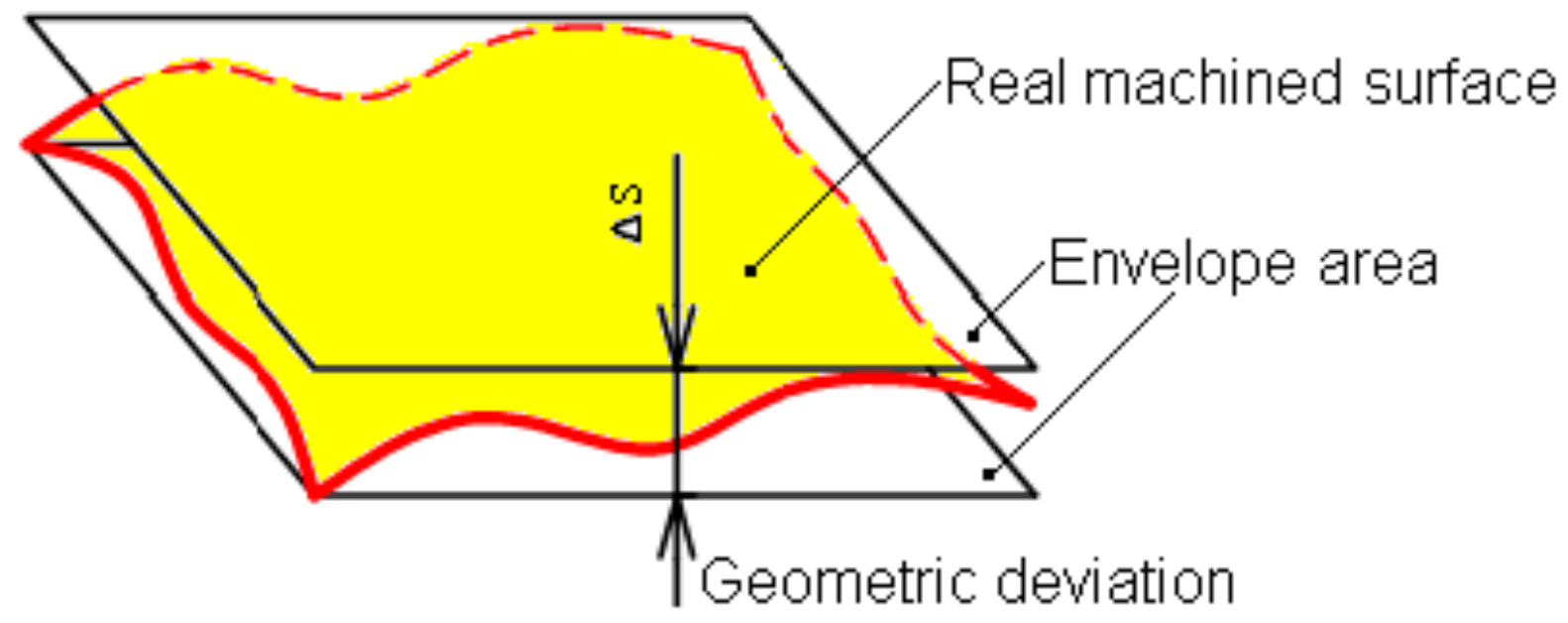
2.1. General Characteristics of Geometric Deviations of Machined Surfaces

In general, machined surfaces [29] do not have absolutely exact dimensions or ideal geometrical shapes [30]. The difference between the required and the real value of the machined surface is quantified by the geometric deviation. As was already mentioned, the geometrical accuracy of the machined surface is in general identified by the shape, orientation, position and run-out deviations. These deviations are quantitatively evaluated as the largest distance of the points of a given area (profile) in the normal direction or as the sum of the absolute values of the greatest distances of the points of the given area (profile) on both sides of the middle element. Figure 1 shows a graphical representation of the principle of identifying the geometric deviation of the shape of the machined surface.
The real machined area is represented by the area that is separated from the surrounding environment by (the ideal) nominal area. The shape and size of the ideal area is determined by a drawing or other technical documentation. The envelope surface has the shape of a nominal surface and touches the real surface. The deviation of the shape of the real surface from the shape of the nominal surface is represented by the greatest distance of the real surface points from the envelope surface, in the normal direction to the envelope surface. The deviation of the mutual position of the real area from the nominal area is characterized by the difference between the largest and the smallest distances between these surfaces within the range of the considered section. By run-out deviation we mean the difference between the largest and smallest distances of the points of the real profile of the rotational surface from the base axis in a plane perpendicular to the base axis. For an objective quantitative evaluation of particular geometric deviations of the machined surface [31,32], it is necessary to carry out measurements on a certain minimum number, n, of samples. When assessing the deviations of the machined surface made by the steady-state machining processes, where the technological impacts on accuracy are predominantly random, it is advisable to perform a check on n ≥ 5 samples. In the case of electrical discharge machining, where the trend of the parameter varying of the geometric deviations is not known, and when systematically variable influences predominate, a much larger number of n samples is necessary. The statistical interpretation of the geometrical accuracy parameters of a given machined surface is, as a rule, performed on the basis of assumptions about the courses and trends of the evaluated parameters. The formulation of these assumptions can also be based on the knowledge gained from the assessment of similar machining processes [33]. From the point of view of the solved problem, we can distinguish machining processes [34,35] which correspond to a certain statistical distribution of the evaluated parameters, and machining processes in which the distribution of the evaluated quantities is unknown. In the case of WEDM, it is a machining process in which the statistical distribution of the assessed geometric deviations is unknown.

2.2. Identification of Geometric Deviations of the Shape of the Machined Surface after WEDM

The emergence of geometrical inaccuracy of the machined surface after WEDM is the result of many factors acting during the machining process [36]. Each of these negative-acting factors is involved in a certain percentage ratio on the resulting geometric inaccuracy of the machined surface. At the same time, each of these factors causes characteristic initial geometrical inaccuracies of the machined surface. These are mainly the deviations of directness, flatness, circularity, cylindricalness and the shape of the surface. The causes of the geometric deviations of the shape of the machined surface after WEDM can therefore be divided into three categories [37]. Table 1 shows the causes of the geometric deviations of the machined surface after WEDM in terms of machine, tool and workpiece.
From the overview of the main causes of geometric deviations of the machined surface after WEDM in Table 1, it can be concluded that the electrical discharge machine itself has some influence on geometrical deviations. However, almost all of the above-mentioned causes of the geometric deviations of the machined surface, which are related to the electrical discharge machine, are predetermined by the quality of the construction of the machine or by its subsequent wear during operation. Therefore, these parameters cannot be affected, so they were excluded from the experiment [38,39]. In addition to the influence of the electrical discharge machine itself [40], the inappropriate choice of process parameters, and parameters related to the properties of the tool and the workpiece, have also decisive influence on the geometrical accuracy of the machined surface after WEDM. These parameters can be affected during the WEDM, so they were further considered during the experiment. These are, for example, parameters related to the MTP, dielectric liquid parameters, tool and workpiece material homogeneity, internal stresses in the machined material and the like. Specifically, MTP settings during WEDM, combined with dielectric fluid parameters and tool and workpiece properties, substantially affect the resulting quality of the machined surface. In addition, with the same properties of wire electrode material and workpiece, a different quality of machined surface material can be achieved by using different machining modes. These are a high-performance machining mode, roughing, standard machining mode, semi-finishing and precise machining mode finishing. A special mode for electrical discharge machining is polishing. Table 2 gives the indicative ranges of the theoretically achievable maximum geometric deviations of the machined surface after WEDM when applying different machine modes.
From the mentioned overview, it can be seen that the highest geometrical precision is achieved by the electrical discharge polishing process, in which low energy of electrical discharges is generally used. On the contrary, the largest deviations of geometrical accuracy of the machined surface after WEDM occur in roughing operations using high discharge energy.
One of the decisive factors that are primarily involved in the resulting geometrical accuracy of the WEDM machined surface is also the wire electrode guiding method. Wrong guiding of the wire electrode may cause excessive vibrations [41] or deformations that undoubtedly will be reflected on the final quality of the machined surface [42]. This adverse effect can be, to a certain extent, eliminated by the optimal tension of the wire electrode (Figure 2). Considering these aspects, the geometric shape deviation can be reduced to less than 10.0 μm in finishing operations (Figure 3).
The amplitude size and character of vibration of the wire electrode are (besides the force of tension) also influenced by the wire diameter, wire material and the range of MTP settings during WEDM. The amplitude of the wire electrode vibration during WEDM can be relatively efficiently modified by various combinations of MTPs and process parameters. For example, it can be a change of the ratio between the discharge pulse on-time duration ton and the pulse off-time duration toff, the change of the feed rate of the wire electrode vf, the change of the method and the intensity of the flushing of the working space by the dielectric fluid, etc.
As mentioned above, the geometrical accuracy of the WEDM-machined surface depends mainly on the kinematic accuracy of the electrical discharge machine as a whole, the precision of the of the wire electrode guiding and also on the setting of the MTP and the process parameters [43]. Generally, it can be qualified by deviations of the shape of a given profile Δs, orientation ∆o, position Δp and run-out Δv. The geometric deviation of the shape of the machined surface Δs is generally determined by the difference in shape of the real surface with respect to its ideal shape. Eelatively frequent errors of the geometric shape of the machined surface after WEDM include the flatness deviation. It is mainly caused by vibration of the machine-tool-workpiece system. When the wire electrode moves along the desired path, especially at larger thicknesses of the machined material, the vibration amplitude of the electrode is significantly increased due to the electric discharge and flow of the dielectric fluid [44]. Deviation of the shape Δs of the real machined surface after WEDM with respect to the required shape can be preliminarily determined by the formula:
s   = δ D E F + δ H T + δ E M + δ E R
where:
  • δDEF—is the deviation caused mainly by the deformations and the inaccuracy of the individual parts of the CNC electrical discharge machine. Since this is a force-less machining, this WEDM error is not very significant. Its size is approximately 3 μm;
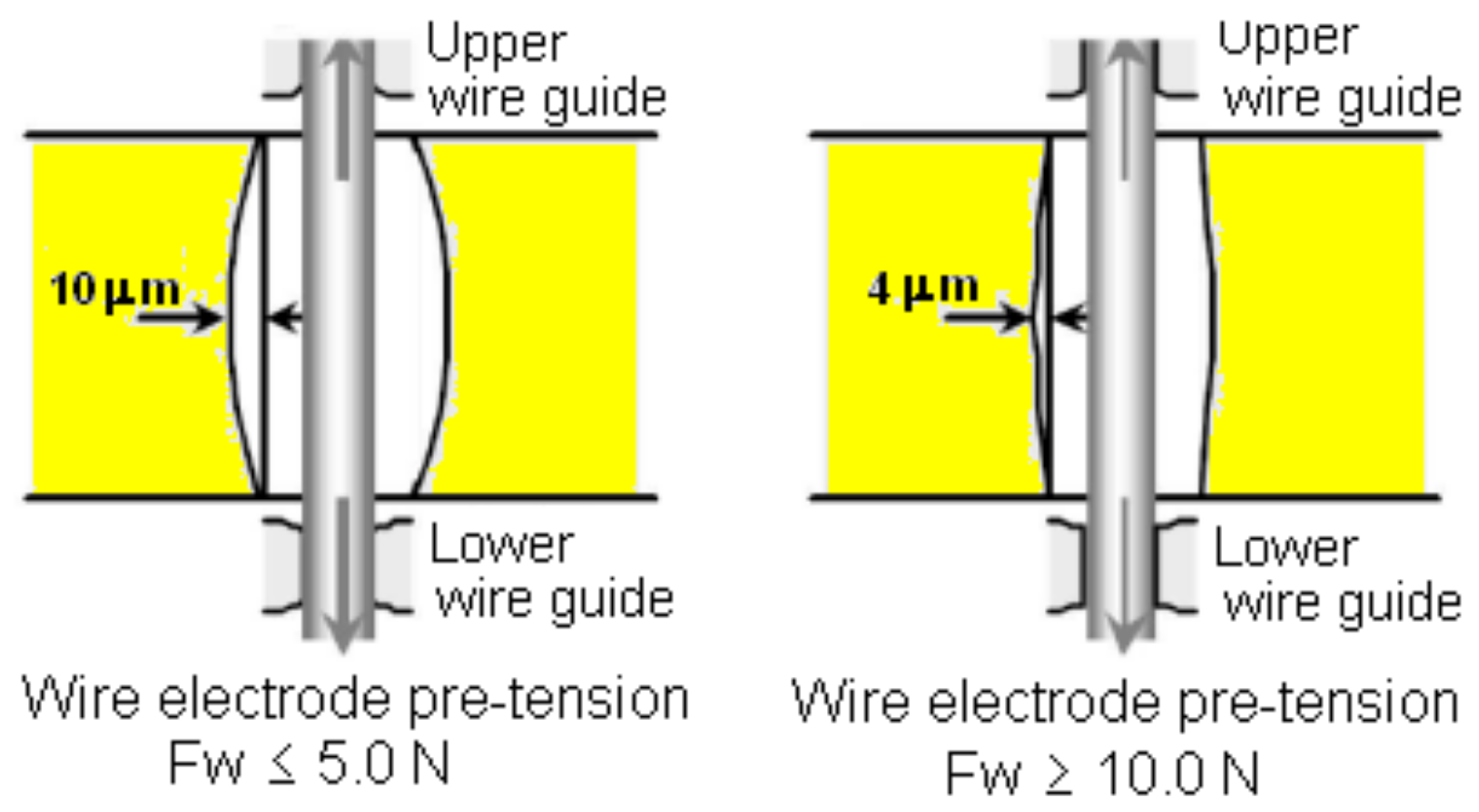
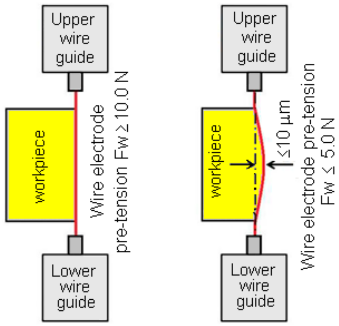
  • δHT—is the deviation that occurs due to the heating of the wire electrode and machined material during electroerosion. This deviation should be considered mainly at the power machining of larger workpiece cross-sections with the use of a wire electrode of larger diameters, or at low cooling capacity of the working space by the dielectric fluid;
  • δEM—is the deviation that arises from flaws in the production of the wire electrode. Its size is within the range of about 2 μm;
  • δER—is the deviation that occurs during the WEDM. It can be compensated by the proper combination of settings of MTP and process parameters.
However, the real value of the shape deviation Δs from the desired shape of the surface after WEDM can only be accurately determined by the experimental measurements.
As mentioned above, the geometrical inaccuracies of the machined surface after WEDM are mainly due to the wear of mechanical parts of the machine, or poor drive control of individual axle drives. To eliminate these effects is, in practice, rather problematic because this would require many complicated interventions in the construction of the technological equipment. However, the deviations of geometrical accuracy caused by the construction of precise and reliable electrical discharge devices are almost negligible compared to errors caused by an improper combination of MTP and process parameters. One of the ways to eliminate the geometrical accuracy errors caused by these factors appears to be the optimizing of these factors. In this case, one of the optimization criteria could be, for example, the minimization of the flatness deviation of the machined surface Δf.

2.3. Conditions of Experiments

Determining the size of the experimental sample is a rather complex process. The size of the sample is influenced by many factors, including the type of the applied machining technology, the required tolerance specifications, the final quality of the machined surface and so on. In the experimental measurement, samples measuring 10.0 × 30.0 mm, and of variable lengths ranging from 20.0 to 100.0 mm were used. These dimensions were determined in accordance with the valid STN ISO/TS 12781-1: 2008 geometric product specifications (GPS) [45]. They were made of tool steel labeled EN X30WCrV9-3 (W.-Nr. 1.2581). It is a high-alloyed, W + Cr + V tool steel with high-strength at high temperatures, good toughness and with resistance to hot tempering. It is used for the production of hot forming tools, shearing tools, fixed, moving parts of pressure die casting molds [46] and the like. Table 3 shows the chemical composition, including the selected mechanical and physical properties of tool steel EN X30WCrV9-3 (W.-Nr. 1.2581).
In order to achieve maximum strength [49] and hardness of the base material [50] without internal stress, the samples were thermally treated by martensitic quenching [51,52] before WEDM. The quenching was performed at a temperature of 1150 °C in oil with subsequent tempering (Figure 4) to a hardness of about 52 HRC at 560 °C to remove internal stresses [53] that arose in the quenching process.
All samples were made on Sodic AQ 535L electrical discharge machine (Figure 5) (Sodick Europe Ltd., Rowley Drive, Baginton, UK). It is an autonomous CNC electrical discharge device [54].
In the experiments, the CuZn37 wire electrode, also referred to as Ms63, with a diameter of 0.20 mm, and the material designation EN CW508L (W.-Nr. 2.0321) was used. This is a 63/37% Cu and Zn compound. The basic mechanical, physical and chemical properties of the material used for the coated wire electrode are given in Table 4.
The working medium was a dielectric liquid based on deionized water. The required properties of the dielectric liquid were achieved with the AMBERLITE MB9L deionization resin. It is a homogeneous mixture of strongly acidic cation exchanger (46–55%) in the form of hydrogen (H+), with strong basic anion exchanger (54–45%) in the form of hydroxide (OH-), with an electrical conductivity of less than 10 μS·cm−1.

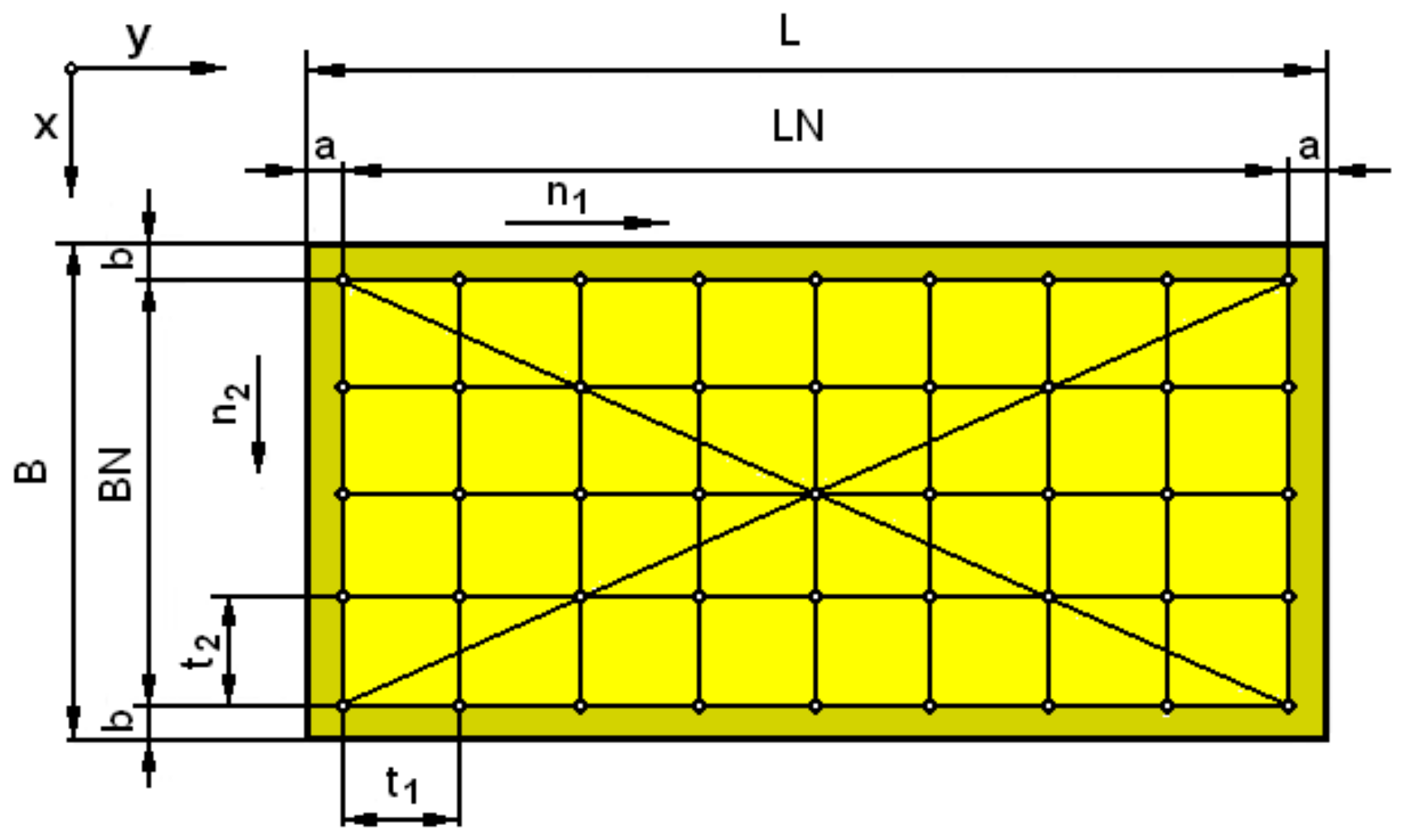
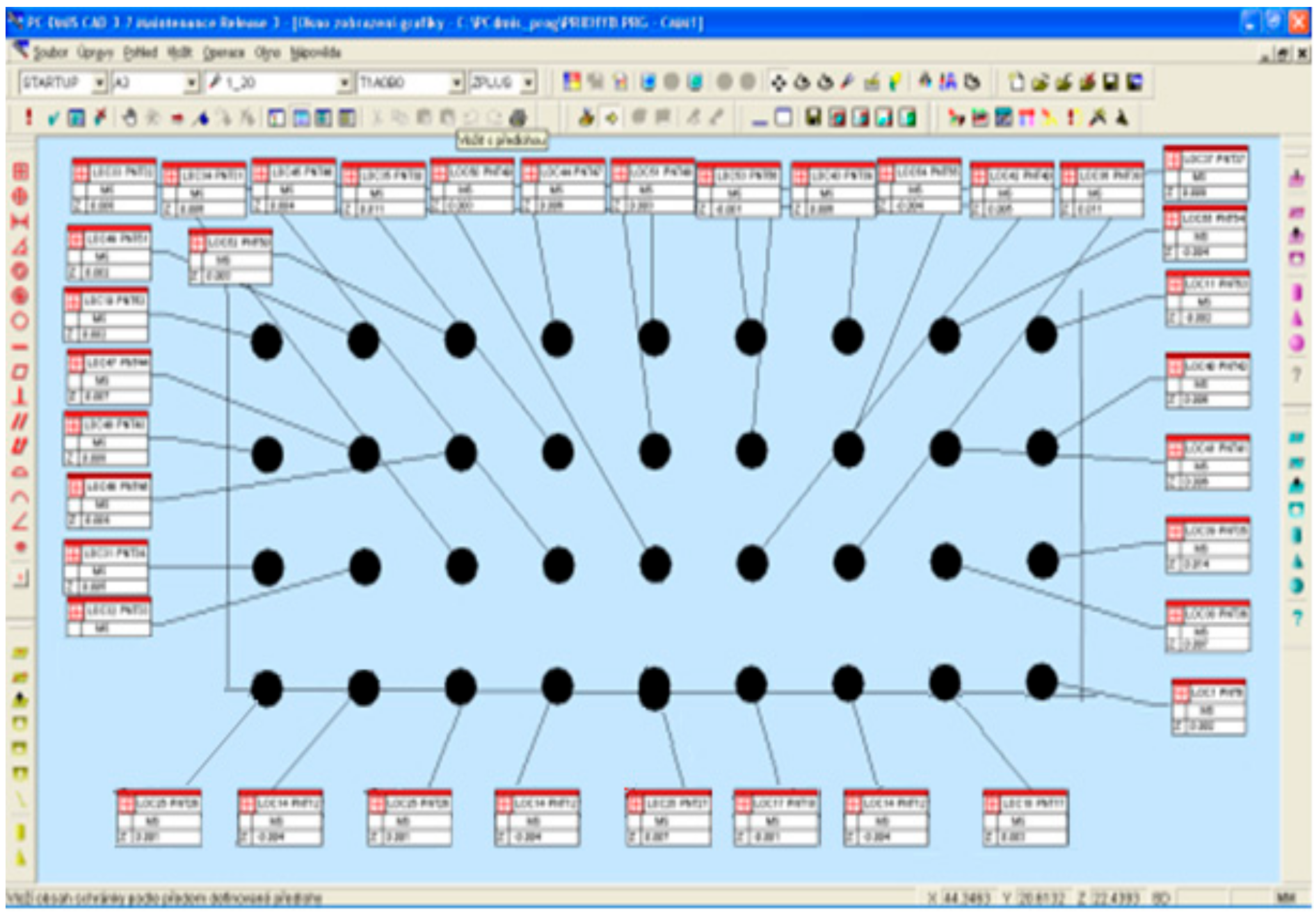
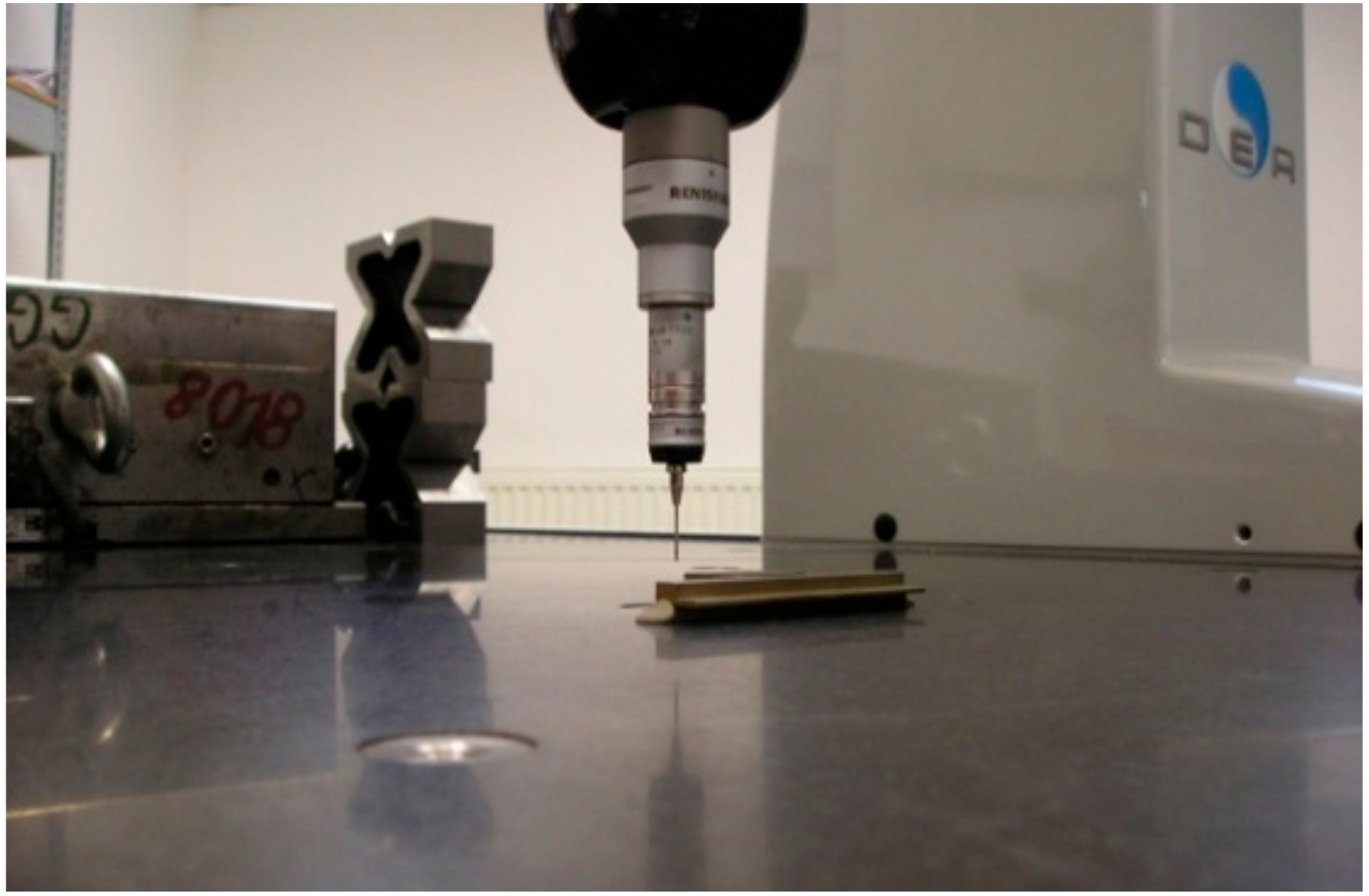
2.4. Determination of Flatness Deviations of Eroded Area of Tool Steel EN X30WCrV9-3 after WEDM with Wire Electrode of 2.0 mm Diameter

There are many methods to measure flatness deviations of a machined surface. One of the effective methods for assessing the flatness of eroded surface after WEDM with wire electrode is 3D measurement using a coordinate measuring device. An important part of identifying the flatness deviation as a partial parameter of the geometrical accuracy of the machined surface after WEDM is a precise set up of an experimental sample on the working table of the measuring device, and the subsequent identification of all the control points of the considered eroded area.
An important part of the preparation of the measurement of the flatness of the machined surface after WEDM on a 3D measuring device is the precise setting (clamping) of an experimental sample on the work table. Incorrect clamping of an experimental sample can lead to deformations, and thus affects the measurement result. The principle of measuring the flatness of the machined surface after WEDM on a 3D portal coordinate measuring device DAE Global Classic (ZA des Bois Blanche, Montoire, France) consists of mechanical contact of the measuring tip with the measured surface. The measured point is recorded at the moment when the measuring tip is deflected so much that either a mechanical contact is interrupted or a sufficiently large force is generated to turn on the pressure sensitive circuit. The signal generated by the metering device provides information to the control computer about the position of the measured point. The measurement is, in general, performed perpendicularly to the measured surface. For measurements at angles greater than 20°, the measurement deviation is approximately 1 μm. Figure 6 illustrates the process of identifying the boundary points of the assessed machined surface after WEDM, and determining of a zero plane of a precisely clamped experimental sample on the working table of the DAE Global Classic 3D portal coordinate measuring device [55].
In the experimental evaluation of the flatness deviations of the machined surface after WEDM, the following sample dimensions were used: 10.0 mm (sample thickness) × 30.0 mm (sample width) and variable length ranging from 20.0–100.0 mm. The samples were made from EN X30WCrV9-3 (W. 1.2581) tool steel using WEDM with CuZn37 wire electrode with 0.20 mm diameter; MTP and process parameters were set to the values that correspond to the roughing, semi-finishing and finishing conditions. The experimental set consisted of 18 samples; for each sample length (20.0; 30.0; 40.0; 50.0; 70.0 and 100.0 mm), three qualitative groups of machined surface were produced. The first qualitative group represented experimental samples with roughness Ra > 2.5 μm, which were made with the highest discharge energy in high-power mode, i.e., by WEDM roughing. The second qualitative group represented experimental samples with roughness within the range 2.5 μm ≥ Ra ≥ 0.80 μm, which were made with standard discharge energy, i.e., WEDM semi-finishing. The final, third, qualitative group represented experimental samples with roughness of Ra < 0.8 μm, which were made with the lowest discharge energy in precision mode, i.e., by WEDM finishing. Another important step in the measurement of deviations of flatness of the eroded surface after WEDM, was the definition of the check points diagram and the determination of the individual spacing in the transverse (x-axis) and longitudinal (y-axis) directions in accordance with the valid standard STN EN ISO 12781-2: 2011-08 01 4408) (geometrical product specifications (GPS), flatness and rectangular grid extraction strategy) [45]. Figure 7 demonstrates the scheme and the check points spacing for measuring the flatness of the eroded area on an experimental sample.
The spacings of the individual check points t1 and t2 in the experimental sample were determined according to the Equations (2) and (3):
t 1 = L N ( n 1 1 ) ;
and t 2 = B N ( n 2 1 )
where:
  • BN—width of the measured area,
  • LN—length of measured area,
  • t1—distance of the measured points in the longitudinal direction,
  • t2—distance of the measured points in the transverse direction,
  • n1—number of measured points in the longitudinal direction,
  • n2—number of measured points in the transverse direction.
Based on these Equations (2) and (3), the spacings t1 and t2 of the individual check points were determined for the measurement of the flatness of the eroded area on experimental samples. Considering width of the experimental samples B = 30.0 mm and the margin width b = 3.0 mm, the check points spacing t2 = 6.0 mm in the transverse direction was selected for all experimental samples. The check points spacing t1 in the longitudinal direction was chosen variably with respect to the variable length L of the experimental samples ranging from 20.0–100.0 mm and the margin width a = 2.0 mm. For sample lengths L = 20.0–30.0 mm spacing t1 = 2.0 mm was chosen, for the sample lengths L = 40.0–50.0 mm spacing t1 = 4.0 mm was chosen, and for the sample lengths L = 70.0–100.0 mm spacing t1 = 6.0 mm was chosen. The identification of the flatness deviations of the eroded area of the experimental sample from tool steel EN X30WCrV9-3 (W.-Nr. 1.2581) at the individual check points according to the established scheme and spacings t1 and t2 was performed using the 3D coordinate measuring device DAE Global Classic (Figure 8).
Figure 9 presents graphic record of flatness deviation of the eroded area of the experimental sample of tool steel EN X30WCrV9-3 40.0 mm in defined check points with longitudinal spacing t1 = 4.0 mm and transverse spacing t2 = 6.0 mm, using 3D coordinate measuring device DAE Global Classic.
The measured values of the flatness deviations of the machined surface at the defined check points of the experimental samples from tool steel EN X30WCrV9-3 (W.-Nr. 1.2581) using WEDM with CuZn37 wire electrode of φ0.20 mm diameter were processed and evaluated by PC-DMIS CAD 3.7 software.

3. Results and Discussion

Complete identification of all checkpoints on the experimental samples from tool steel EN X30WCrV9-3 (W.-Nr. 1.2581) after WEDM using the 3D coordinate measuring device DAE Global Classic was carried out. The flatness deviation courses for the individual lengths L of the samples and for the particular qualitative levels of the eroded surface (roughing, semi-finishing and finishing) were determined. Experimental measurements have shown deformation or curvature in certain parts of the profile of the machined surface, which varied both with the changed length of the eroded surface L and with the change of the quality of the machined surface. During the experiment, it was also found that the characteristic curvature of the machined surface after WEDM is mainly related to the vibration amplitude of the CuZn37 wire electrode with 0.20 mm diameter. Research has also shown that the magnitude and shape of the amplitude can be relatively efficiently modified by varying the intensity of the electrical discharge. As is generally known, the intensity of the electrical discharge is determined by the combination of the MTP setting and the process parameters. Consequently, the vibration of the wire electrode can be modified by a targeted selection of MTP settings and process parameters settings.
As mentioned earlier, oscillation of the wire electrode can be positively influenced to a certain extent by an increase of the tensioning force of the wire Fw. However, its maximum value must respect the mechanical and physical properties of the material EN CW508L (W.-Nr. 2.0321) of the CuZn37 wire electrode with a diameter of 0.20 mm. The value of the force Fw must under no circumstances exceed the critical value of the wire electrode material strength. Otherwise, it would be destroyed. Since during WEDM the values of the tensioning force Fw of CuZn37 wire electrode of 0.20 mm diameter were chosen close to the upper critical values, it is not possible to suppose a positive influence on the quality of the machined surface by a higher tension of the wire electrode. A good way to eliminate wire electrode vibration, therefore, appears to be the optimal setting of MTP values and process parameter values. This way, the resulting machined surface quality after WEDM can be changed, not only in terms of geometrical accuracy, but also in terms of surface roughness (SR) parameters.
The preliminary study of the impact of MTP and process parameters at WEDM on the geometrical accuracy of the machined surface in terms of flatness deviation Δf has revealed several facts. It has been found, for example, that the pulse on-time duration ton, together with the electric discharge intensity between the wire electrode and the machined material, determined by the discharge peak current I and voltage of discharge U, in combination with the pulse off-time duration toff, create specific deflection. However, it is important to note that the extent of the flatness deviations of the eroded area Δf after WEDM is in the range of tens of micrometers.
Figure 10 shows graphical dependence that describes the shape and size of the flatness deviation ΔfR of the machined surface of the tool steel EN X30WCrV9-3 after WEDM roughing at eroded surface lengths L ranging from 20.0 to 100.0 mm.
From the graphical dependence on Figure 10 it can be observed that WEDM roughing with CuZn37 wire electrode of 0.20 mm diameter leads to a convex curvature of the eroded surface of tool steel EN X30WCrV9-3. In addition, with increasing length of the eroded surface L, the flatness deviation of the machined surface is considerably increased. Its maximum value ΔfR = 25.0 μm was obtained after the roughing operation for the eroded area of length L = 100.0 mm. On the contrary, the lowest value ΔfR = 10.0 μm was achieved at the eroded area length L = 20.0 mm.
The graphical dependence in Figure 11 describes the shape and size of the flatness deviation ΔfSF of the eroded surface of tool steel EN X30WCrV9-3 after WEDM semi-finishing operation at various eroded surface lengths L ranging from 20.0–100.0 mm.
From Figure 11, it can be concluded that WEDM semi-finishing with CuZn37 wire electrode of 0.20 mm diameter causes concave curvature of the machined surface of tool steel EN X30WCrV9-3. In WEDM roughing and WEDM semi-finishing the deformation of the eroded surface ΔfSF increases significantly with the increasing length of the eroded surface L. Its maximum value ΔfSF = 15.0 μm was obtained after the semi-finishing operation of the eroded surface length L = 100.0 mm. On the other hand, the lowest value ΔfSF = 4.0 μm was achieved at the eroded surface length L = 20.0 mm.
The graph on Figure 12 describes the shape and size of the flatness deviation ΔfF of the eroded surface of tool steel EN X30WCrV9-3 after WEDM finishing operation at various eroded surface lengths L in the range from 20.0–100.0 mm.
The graphical dependence in Figure 12 shows that at WEDM, finishing with CuZn37 wire electrode of 0.20 mm diameter a concave curvature of eroded surface takes place when machining tool steel EN X30WCrV9-3, the same as with WEDM finishing. However, the flatness deviation of the eroded area ΔfF achieved after the WEDM finishing is slightly smaller compared to the WEDM semi-finishing operation. In WEDM roughing and semi-finishing the eroded surface flatness deviation substantially increases with the increasing length of the eroded surface L. Its maximum size is ΔfF = 9.0 μm for the eroded surface length L = 100.0 mm. On the contrary, the lowest ΔfF = 2.0 μm was achieved at the erosion surface length L = 20.0 mm.
Figure 13 is a graphical dependence that shows the effect of length L on the maximum flatness deviation Δfmax of the eroded surface of tool steel EN X30WCrV9-3 (W.-Nr. 1.2581) after WEDM roughing, semi-finishing and finishing with CuZn37 wire electrode of 0.20 mm diameter. The graph in Figure 13 is divided into two areas. The beige area in the graph presents values of maximum flatness deviation Δfmax that were obtained experimentally. The yellow area in the graph presents values of maximum flatness deviation Δfmax that were predicted on the basis of 2nd degree polynomial function.
From the graphical dependence in Figure 13, it can be observed that with increasing length of the eroded surface L in the range from 5.0–150.0 mm, the maximum flatness deviation Δfmax of the eroded surface of tool steel EN X30WCrV9-3 after WEDM roughing, semi-finishing and finishing increases by the polynomial functions. The values of the maximum flatness deviation Δfmax of the eroded area in the length range L = 20.0–100.0 mm (beige area in Figure 13) refer to experimentally measured values. The values of the maximum flatness deviation Δfmax of the eroded surface of the length range L = 5.0–20.0 mm and L = 100.0–150.0 mm (yellow area in Figure 13) refer to the predicted values. At the constant length L, the size of the maximum flatness deviation Δfmax of the eroded surface is substantially smaller after WEDM finishing operation compared to the roughing and semi-finishing operations.
The value of the experimentally measured maximum flatness deviation Δfmax of the eroded surface in the length range L = 20.0–100.0 mm varies, depending on the WEDM operation, from 2.0–25.0 μm. Specifically, in the range of 2.0–9.0 μm for finishing operations, 4.0–15.0 μm for semi-finishing operations and 10.0–25.0 μm for roughing operations. From the experimental results, it can be concluded that the smallest flatness deviation of eroded surface Δfmax = 2.0 μm occurs for eroded surface length L ≤ 20.0 mm after WEDM finishing of tool steel EN X30WCrV9-3 with CuZn37 wire electrode of 0.20 mm diameter. On the contrary, the largest deviations of the flatness of the machined surface (25.0 μm) occur at lengths L ≥ 100.0 mm with the application of WEDM roughing.
The predicted maximum flatness deviation Δfmax of the eroded surface in the range L = 5.0–20.0 mm, depending on the WEDM operation, ranges from 1.8–10.0 μm. Specifically, in the range of 1.8–2.0 μm for finishing operations, 3.8–4.0 μm for semi-finishing operations and 9.5–10.0 μm for roughing operations. The predicted maximum flatness deviation Δfmax of the eroded surface in the range L = 100.0–150.0 mm, depending on the WEDM operation, ranges from 9.0–45.0 μm. Specifically, in the range of 9.0–18.0 μm for finishing operations, 15.0–27.0 μm for semi-finishing operations and 25.0–45.0 μm for roughing operations. From the results of the predicted values of the maximum flatness deviation of the eroded surface, it follows that the lowest value Δfmax = 1.8 μm can be achieved at the length of the eroded area L ≤ 5.0 mm with WEDM finishing. On the other hand, the highest value Δfmax = 45.0 μm is achieved with the eroded surface length L ≥ 150.0 mm with the application of WEDM roughing.
From the dependence in Figure 13, which summarizes the effect of individual WEDM operations on the maximum flatness deviation Δfmax of the machined surface of tool steel EN X30WCrV9-3 with CuZn37 wire electrode of 0.20 mm diameter, for different lengths of eroded area L in the range from 5.0–150.0 mm, several facts can be stated. It has been found that with the increasing length of the eroded surface L, the maximum flatness deviation Δfmax and its curvature in WEDM roughing, as well as in semi-finishing and finishing, is significantly increased. At the same time, it can be observed that the lowest values of the maximum flatness deviation were achieved at WEDM finishing. The values Δfmax of eroded surface of tool steel EN X30WCrV9-3 after WEDM at L = 5.0–150.0 mm are in the range from 1.8–45.0 μm, namely 9.5–45.0 μm for roughing operations, 3.8–27.0 μm for semi-finishing operations and 1.8–18.0 μm for finishing operations. From the graphical dependencies shown in Figure 8, Figure 9 and Figure 10, the orientation and the shape of the curvature of the eroded surface can also be observed in its dependence on the WEDM type of operation and its length L. The WEDM roughing operation produces a convex curvature of the eroded surface, while concave curvature is the result of the semi-finishing and finishing operation.

Practical Recommendations for Optimizing of the Size of Maximum Deviation Δfmax of the Eroded Surface

Based on the results of the experimental measurements and the predicted values of the maximum flatness deviation Δfmax of the eroded surface of tool steel EN X30WCrV9-3 after WEDM with CuZn37 wire electrode of 0.20 mm diameter, it can be stated that the combination of MTP settings and process parameters have significant influence on the size and curvature shape of Δfmax course. From the graphical dependencies shown in Figure 10, Figure 11 and Figure 12, the specific shapes of curvature of the eroded surfaces of tool steel EN X30WCrV9-3 achieved in individual WEDM operations can be observed. After WEDM roughing, a convex curvature of the machined surface can be observed, i.e., curvature towards the inside of the workpiece. This type of curvature occurs in roughing operations because the CuZn37 wire electrode passes through the full material. This results in the maximum oscillation amplitude of the wire electrode approximately at the center of the eroded surface profile. With this machining method, the wire electrode is active on 50% of its surface area. This high proportion of the active surface area of the wire electrode causes extreme stress of the electrode, especially in the center of eroded surface. The effect of high-intensity discharges between the wire electrode and the eroded material also results in a convex curvature (into the material) of the machined surface. This type of shape inaccuracy causes problems in practice, for example, in the precise joining of parts where the convex curvature of the machined surface causes loosening in pressed joints with little overlapping. After WEDM semi-finishing and finishing of tool steel EN X30WCrV9-3 with CuZn37 wire electrode of 0.20 mm diameter, the opposite effect can be observed. In these erosion processes, the wire electrode passes through the eroded area offset. In this case, the forces of the electric discharge push the wire electrode away from the surface of the machined material, approximately at the center of the profile of the machined surface, which causes concave curvature on the material surface. With this machining method, the wire electrode passes through the edge of the workpiece by the so-called offset, acting on about 25% of its surface. This relatively low proportion of the active surface area of the wire electrode, combined with the low intensity of the electrical discharges in this machining process, has much less negative influence on the flatness deviation of the eroded surface. In this method, the WEDM eroded surface has the shape of a slight concave curvature. Despite the relatively small curvature deviation, which is in the μm range, this deficiency is reinforced by the fact that it occurs in combination with low surface roughness (SR) of eroded material. When assembling components made by WEDM finishing, the opposite effect occurs compared to WEDM roughing. When assembling the joints with clearance (movable joints), the components are pressed together and form an unwanted rigid pressed joint. In case of pressed joints with overlapping, the concave curvature of the machined surface produces an uneven distribution of force effects, with higher self-locking forces acting in the center. At the same time, there is a clearance in peripheral parts. In addition, this qualitative deficiency at WEDM finishing is further reinforced due to the very low values of the roughness parameters of the eroded surface (Ra ≤ 0.8 μm). By increasing the number of offset cuts using low discharge energy, the concave curvature can be substantially eliminated. Here, however, it should be noted that increasing the number of offset cuts, in practice, prolongs the machining time and thus aggravates the machining economy. Therefore, it is necessary to choose an optimal number of offset cuts with low discharge energy regarding the resulting eroded surface quality, not only in terms of the maximum flatness deviation Δfmax, but also in terms of the roughness parameters of the eroded surface and the overall economy during WEDM.

4. Conclusions

An important quantitative parameter in the complex assessment of the eroded surface quality after WEDM is, in addition to surface roughness parameters, the maximum flatness deviation of the eroded surface. Even though WEDM is one of the most accurate progressive machining technologies, in practice there are some deficiencies in the quality of the eroded surface in terms of geometrical accuracy. This shortcoming is mostly due to the flatness deviations of the eroded surface. The aim of the experiment was to carry out detailed research of the geometrical accuracy of the machined surface in terms of the maximum flatness deviation of the eroded surface after WEDM of tool steel EN X30WCrV9-3 with CuZn37 wire electrode of 0.20 mm diameter. Within the experiment, the influence of the eroded surface length L in each WEDM method on the range of deficiencies concerning the geometrical accuracy of the eroded surface, was precisely assessed in terms of the maximum flatness deviation Δfmax. The aim was also to propose possible measures to eliminate the negative influence of geometrical inaccuracy on finished products. The experiments have shown essential differences in the shape of curvature and the size of the maximum flatness deviations Δfmax between WEDM roughing, semi-finishing and finishing.
Summary of experimental research results:
based on the preliminary analysis of the geometrical accuracy of the eroded surface, particular types of geometrical accuracy deficiencies that were encountered in the WEDM of tool steels with the CuZn37 wire electrode were identified;
the possible causes of the geometric inaccuracy of the eroded surface of tool steel EN X30WCrV9-3 with CuZn37 wire electrode of 0.20 mm diameter were determined;
MTP and process parameters that significantly affect the geometrical accuracy of the eroded tool steel surface after WEDM in terms of maximum flatness deviation Δfmax were defined;
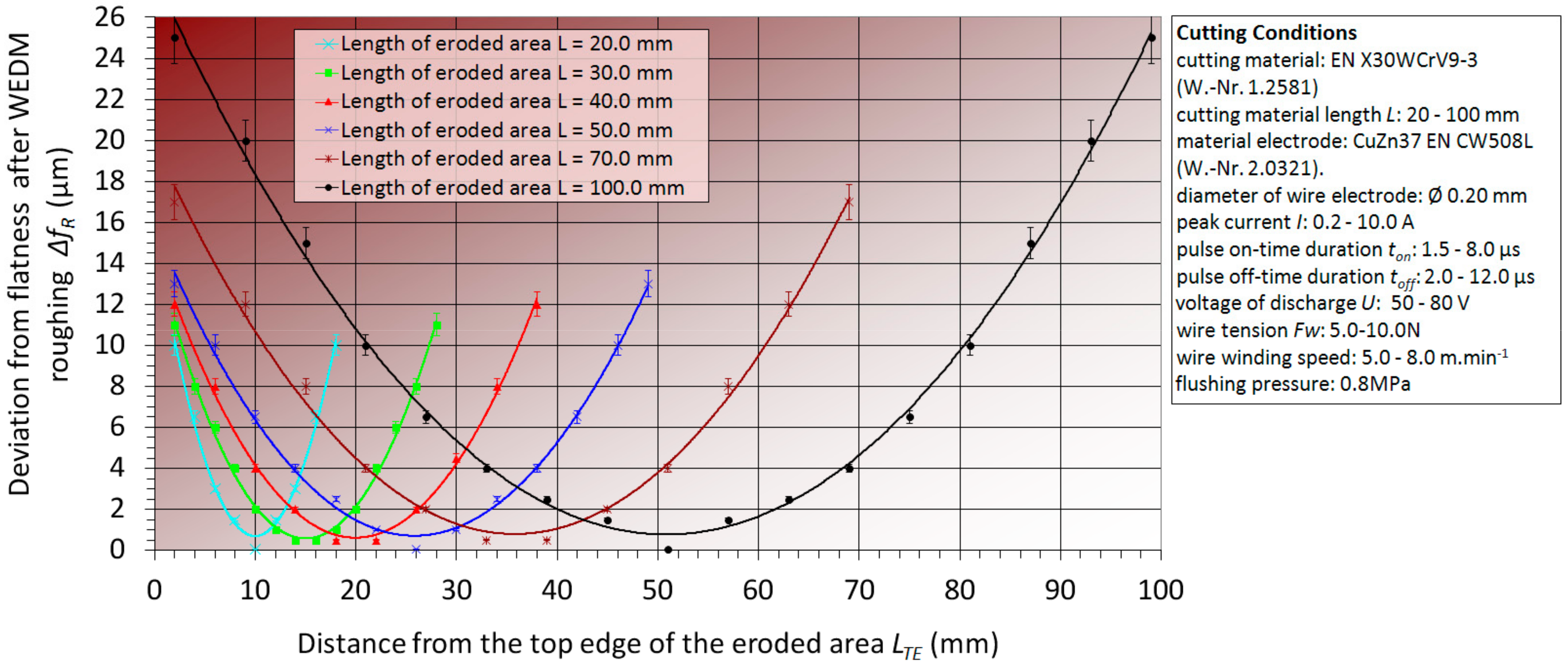
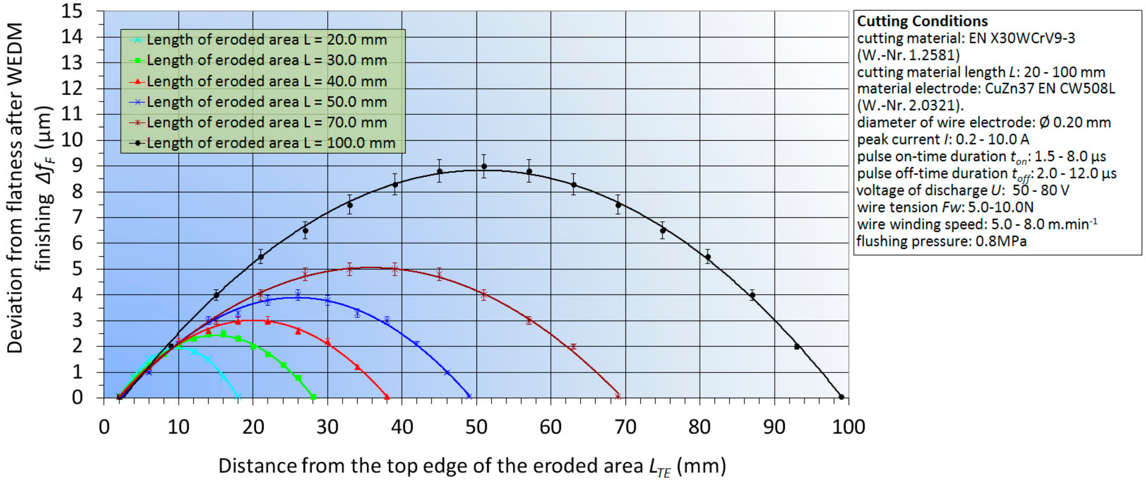
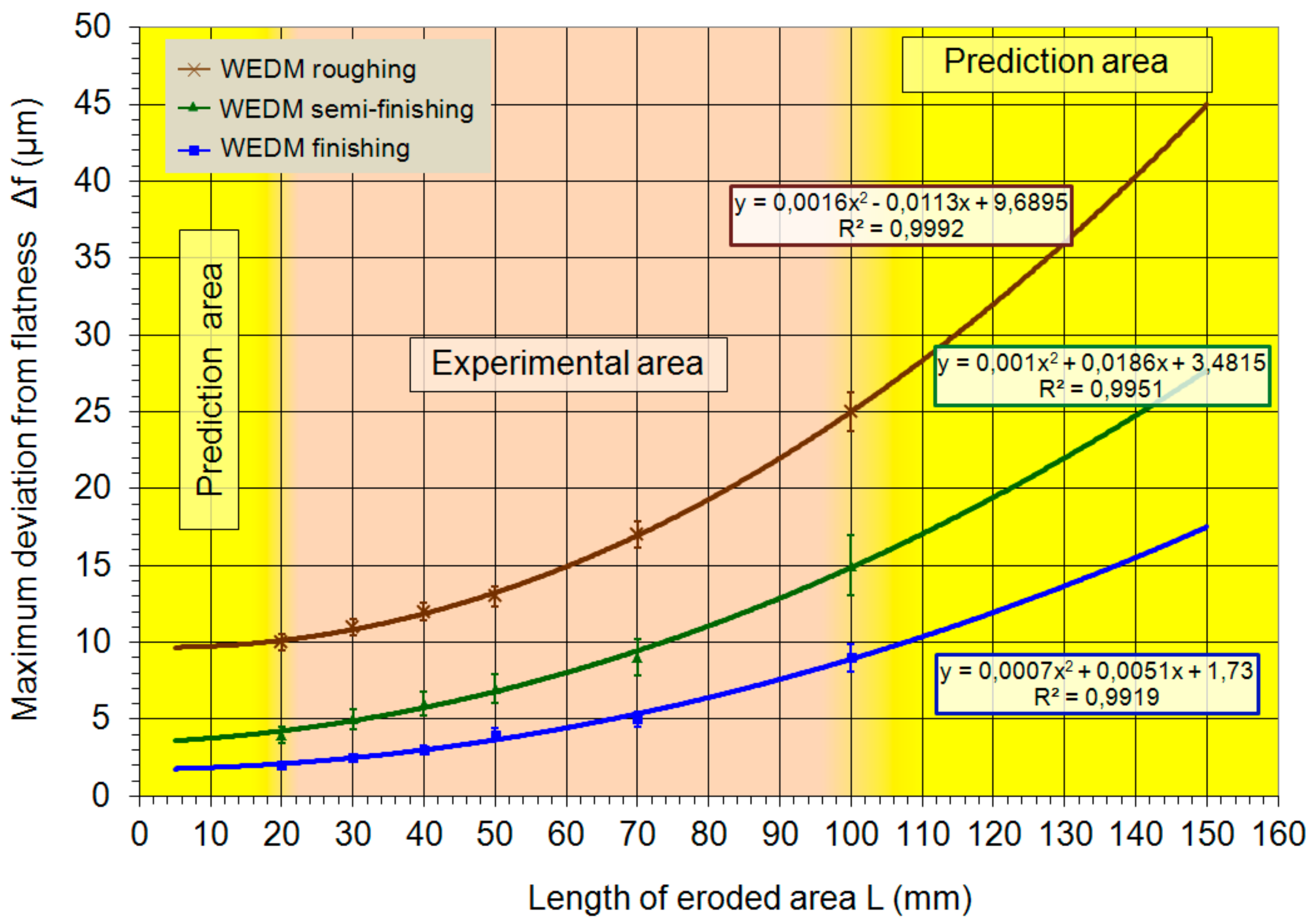
experimentally, significant deviations were observed in the shape of the curvature but also in the maximum flatness deviation Δfmax of the eroded surface between the WEDM roughing, semi-finishing and finishing operations. The maximum value of the flatness deviation Δfmax = 25.0 μm of eroded surface of tool steel EN X30WCrV9-3 was recorded at WEDM roughing. Conversely, the lowest parameter value Δfmax = 2.0 μm was recorded at WEDM finishing;
differences of measured values of the maximum flatness deviation Δfmax of the eroded surface in individual WEDM operations, in its dependence on the change of the total length of the eroded surface L were also found. Maximum flatness deviation at WEDM ranged for roughing from 10.0 μm–25.0 μm, for semi-finishing from 4.0–15.0 μm, for finishing from 2.0–9.0 μm. The lower values apply for length L = 20.0 mm, the higher for L = 100.0 mm;
values of the maximum flatness deviation Δfmax of the eroded area were predicted for individual WEDM operations, depending on the change of the total length of the eroded surface L in the range from 5.0–20.0 mm and in the range from 100.0–150.0 mm. The lowest parameter value Δfmax = 1.8 μm was predicted for WEDM finishing with eroded surface length L = 5.0 mm. Conversely, the highest parameter value Δfmax = 45.0 μm was predicted for WEDM roughing with eroded surface length L = 150.0 mm;
research of the maximum flatness deviation of the eroded surface of tool steel EN X30WCrV9-3 after WEDM with CuZn37 wire electrode of 0.20 mm diameter, was oriented with regard to the practical use of the acquired experimental results for the theory, as well as technical practice;
achieved results and the proposed recommendations for practice allow to meet much narrower specification of the demands placed on the quality of the eroded surface in terms of geometrical accuracy after WEDM with CuZn37 wire electrode.

Acknowledgments

This research work was supported by the Slovak Research and Development Agency under the contract No. APVV-15-0602 and also by the Project of the Structural Funds of the EU, ITMS code 26220220103.

Author Contributions

Ľuboslav Straka conceived and designed the experiments; Ľuboslav Straka and Ivan Čorný performed the experiments; Ľuboslav Straka and Ján Piteľ analyzed the data; Ľuboslav Straka wrote the paper.

Conflicts of Interest

The authors declare no conflicts of interests.

References

  1. Gupta, K.; Jain, N.K. Manufacturing of high quality miniature gears by wire electric discharge machining. In Chapter 40 in DAAAM International Scientific Book; DAAAM International: Vienna, Austria, 2013; pp. 679–696. [Google Scholar]
  2. Garg, M.P.; Jain, A.; Bhushan, G. An Investigation into Dimensional Deviation Induced by Wire Electric Discharge Machining of High temperature Titanium alloy. J. Eng. Technol. 2012, 2, 104–112. [Google Scholar] [CrossRef]
  3. Kanlayasiri, K.; Jattakul, P. Simultaneous optimization of dimensional accuracy and surface roughness for finishing cut of wire-EDMed K460 tool steel. Precis. Eng. 2013, 37, 556–561. [Google Scholar] [CrossRef]
  4. Puri, A.B.; Bhattacharyya, B. An analysis and optimization of the geometrical in accuracy due to wire lag phenomenon in WEDM. Int. J. Mach. Tools Manuf. 2003, 43, 151–159. [Google Scholar] [CrossRef]
  5. Sanchez, J.A.; Rodil, J.L.; Herrero, A.; Lopez de Lacalle, L.N.; Lamikiz, A. On the influence of cutting speed limitation on the accuracy of wire-EDM corner-cutting. J. Mater. Process. Technol. 2007, 182, 574–579. [Google Scholar] [CrossRef]
  6. Puri, A.B.; Bhattacharyya, B. Modelling and analysis of the wire-tool vibration in wire-cut EDM. J. Mater. Process. Technol. 2003, 141, 295–301. [Google Scholar] [CrossRef]
  7. Huang, J.T.; Liao, Y.S.; Hsue, W.J. Determination of finish-cutting operation number and machining-parameters setting in wire electrical discharge machining. J. Mater. Process. Technol. 1999, 87, 69–81. [Google Scholar] [CrossRef]
  8. Dodun, O.; Gonçalves-Coelho, A.M.; Slătineanu, L.; Nagîţ, G. Using wire electrical discharge machining for improved corner cutting accuracy of thin parts. Int. J. Adv. Manuf. Technol. 2009, 41, 858–864. [Google Scholar] [CrossRef]
  9. Lin, C.T.; Chung, I.F.; Huang, S.Y. Improvement of machining accuracy by fuzzy logic at corner parts for wire-EDM. Fuzzy Set. Syst. 2001, 122, 499–511. [Google Scholar] [CrossRef]
  10. Chen, Z.; Huang, Y.; Zhang, Z.; Li, H.; Ming, W.; Zhang, G. An analysis and optimization of the geometrical inaccuracy in WEDM rough corner cutting. Int. J. Adv. Manuf. Technol. 2014, 74, 917–929. [Google Scholar] [CrossRef]
  11. Shahane, S.; Pande, S.S. Development of a thermo-physical model for multi-spark wire EDM process. Procedia Manuf. 2016, 5, 205–219. [Google Scholar] [CrossRef]
  12. Kapoor, J.; Singh, S.; Khamba, J.S. Effect of cryogenic treated brass wire electrode on material removal rate in wire electrical discharge machining. Proc. Inst. Mech. Eng. Part C J. Mech. Eng. Sci. 2012, 226, 2750–2758. [Google Scholar] [CrossRef]
  13. Singh, H. Experimental study of distribution of energy during EDM process for utilization in thermal models. Int. J. Heat Mass Tranf. 2012, 55, 5053–5064. [Google Scholar] [CrossRef]
  14. Sugimura, K.; Iwamoto, K.; Izumida, H. New High-Speed Precision Steel Core EDM Wire with New Alloy Coating (SUMISPARK Gamma). Sei Tech. Rev. 2015, 81, 77–83. [Google Scholar]
  15. Kumara, V.; Jangrab, K.K.; Kumarc, V. An experimental study on trim cutting operation using metal powder mixed dielectric in WEDM of Nimonic-90. Int. J. Ind. Eng. Comput. 2016, 7, 135–146. [Google Scholar] [CrossRef]
  16. Antar, M.T.; Soo, S.L.; Aspinwall, D.K.; Jones, D.; Perez, R. Productivity and workpiece surface integrity when WEDM aerospace alloys using coated wires. Procedia Eng. 2011, 19, 3–8. [Google Scholar] [CrossRef]
  17. Yan, M.; Huang, P. Accuracy improvement of wire-EDM by real-time wire tension control. Int. J. Mach. Tools Manuf. 2004, 44, 807–814. [Google Scholar] [CrossRef]
  18. Krenický, T.; Marcin, J.; Švec, P. Magnetic properties of FeCoNbB nanocrystalline alloys heat treated under longitudinal magnetic field. Czechoslovak J. Phys. 2004, 54, 185–188. [Google Scholar] [CrossRef]
  19. Dubják, J.; Piteľ, J.; Tóthová, M. Diagnostics of aluminum alloys melting temperature in high pressure casting. Key Eng. Mater. 2016, 669, 110–117. [Google Scholar] [CrossRef]
  20. Che Haron, C.H. Investigation on the influence of machining parameters when machining tool steel using EDM. J. Mater. Process. Technol. 2001, 1, 84–87. [Google Scholar] [CrossRef]
  21. Fuzhu, H.; Jie, Z.; Isago, S. Corner error simulation of rough cutting in wire EDM. Precis. Eng. 2007, 31, 331–336. [Google Scholar]
  22. Lin, P.D.; Liao, T.T. An effective-wire-radius compensation scheme for enhancing the precision of wire-cut electrical discharge machines. Int. J. Adv. Manuf. Technol. 2009, 40, 324–331. [Google Scholar] [CrossRef]
  23. Straka, Ľ.; Hašová, S. Assessing the influence of technological parameters on the surface quality of steel MS1 after WEDM. MM Sci. J. 2016, 11, 1194–1200. [Google Scholar] [CrossRef]
  24. Hašová, S.; Straka, Ľ. Design and verification of software for simulation of selected quality indicators of machined surface after WEDM. Acad. J. Manuf. Eng. 2016, 14, 13–20. [Google Scholar]
  25. Abu Zeid, O.A. On the effect of electro-discharge machining parameters on the fatigue life of AISI D6 tool steel. J. Mater. Process. Technol. 1997, 68, 27–32. [Google Scholar] [CrossRef]
  26. Saha, S.K.; Chaudhary, S.K. Experimental investigation and empirical modeling of the dry electrical discharge machining process. Int. J. Mach. Tools Manuf. 2009, 49, 297–308. [Google Scholar] [CrossRef]
  27. Stephen, P.; Radzevich, P.S.; Kreheľ, R. Application priority mathematical model of operating parameters in advanced manufacturing technology. Int. J. Adv. Manuf. Technol. 2011, 56, 835–840. [Google Scholar]
  28. Tóthová, M.; Balara, M.; Dubják, J. Simulation model of cascade control of the heating system. Int. J. Eng. Res. Afr. 2015, 18, 20–27. [Google Scholar] [CrossRef]
  29. Duplák, J.; Hatala, M.; Michalik, P. Durability analysis for selected cutting tools in machining process of steel 16mov6-3. Appl. Mech. Mater. 2013, 308, 133–139. [Google Scholar] [CrossRef]
  30. Mičietová, A.; Neslušan, M.; Čilliková, M. Influence of surface geometry and structure after non-conventional methods of parting on the following milling operations. Manuf. Technol. 2013, 13, 199–204. [Google Scholar]
  31. Kreheľ, R.; Pollák, M. The contactless measuring of the dimensional attrition of the cutting tool and roughness of machined surface. Int. J. Adv. Manuf. Technol. 2016, 86, 437–449. [Google Scholar] [CrossRef]
  32. Baron, P.; Zajac, J.; Pollák, M. The correlation of parameters measured on rotary machine after reparation of disrepair state. MM Sci. J. 2016, 11, 1244–1248. [Google Scholar] [CrossRef]
  33. Marafona, J.; Wykes, C. A new method of optimizing material removal rate using EDM with copper–tungsten electrodes. Int. J. Mach. Tools Manuf. 2000, 40, 153–164. [Google Scholar] [CrossRef]
  34. Mathew, S.; Varma, P.R.D.; Kurian, P.S. Study on the influence of process parameters on surface roughness and MRR of AISI 420 stainless steel machined by EDM. Int. J. Eng. Trends Technol. 2014, 2, 54–58. [Google Scholar] [CrossRef]
  35. Kiyak, M.; Cakir, O. Examination of machining parameters on surface roughness in EDM of tool steel. J. Mater. Process. Technol. 2007, 1–3, 141–144. [Google Scholar] [CrossRef]
  36. Panda, A.; Duplák, J.; Hatala, M.; Krenický, T.; Vrábel, P. Research on the durability of selected cutting materials in the process of turning carbon steel. MM Sci. J. 2016, 11, 1086–1089. [Google Scholar] [CrossRef]
  37. Straka, Ľ. Analysis of Wire-Cut Electrical Discharge Machined Surface; LAP Lambert Academic Publishing: Saarbrücken, Germany, 2014; p. 98. [Google Scholar]
  38. Monka, P.P.; Monková, K.; Balara, M.; Hloch, S.; Rehor, J.; Andrej, A.; Šomšák, M. Design and experimental study of turning tools with linear cutting edges and comparison to commercial tools. Int. J. Adv. Manuf. Technol. 2016, 85, 2325–2343. [Google Scholar] [CrossRef]
  39. Neslušan, M.; Turek, S.; Brychta, J.; Čep, R.; Tabaček, M. Experimental Methods in Splinter Machining; EDIS, University of Žilina: Žilina, Slovakia, 2007; p. 343. [Google Scholar]
  40. Michalik, P.; Zajac, J.; Hatala, M.; Duplák, J.; Mitaľ, D. Comparison of programming production of thin walled parts using different CAM systems. MM Sci. J. 2016, 10, 1056–1059. [Google Scholar] [CrossRef]
  41. Olejárová, Š.; Krenický, T. Monitoring the condition of the spindle of the milling machine using vibration. MM Sci. J. 2016, 11, 1227–1231. [Google Scholar] [CrossRef]
  42. Panda, A.; Prislupčák, M.; Pandová, I. Progressive technology diagnostic and factors affecting to machinability. Appl. Mech. Mater. 2014, 616, 183–190. [Google Scholar] [CrossRef]
  43. Straka, Ľ.; Čorný, I.; Pitel, J.; Hašová, S. Statistical Approach to Optimize the Process Parameters of HAZ of Tool Steel EN X32CrMoV12-28 after Die-Sinking EDM with SF-Cu Electrode. Metals 2017, 7, 35. [Google Scholar] [CrossRef]
  44. Straka, Ľ.; Hašová, S. Study of tool electrode wear in EDM process. Key Eng. Mater. 2016, 669, 302–310. [Google Scholar] [CrossRef]
  45. STN EN ISO 12781-2:2011-08 (01 4408) Geometrical Product Specifications (GPS). Available online: https://www.evs.ee/preview/iso-12781-2-2011-en.pdf (accessed on 25 August 2017).
  46. Rimár, M.; Fedák, M.; Kulikov, A.; Šmeringai, P. Dependence of hardness of continues die-casting products on Fe content. MM Sci. J. 2016, 11, 1201–1204. [Google Scholar] [CrossRef]
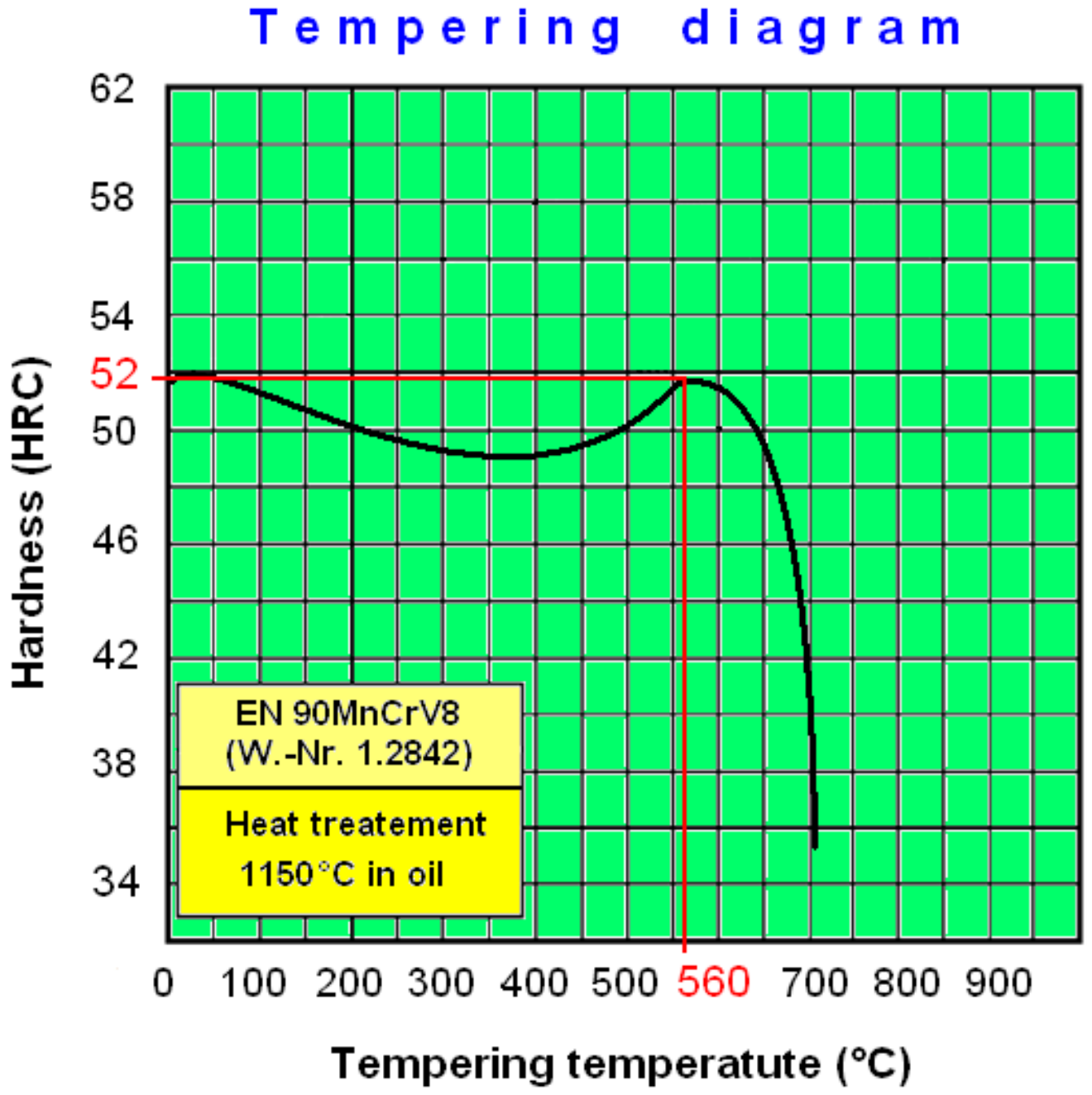
  47. Chemical Composition and Tempering Diagram of Tool Steel EN X30WCrV9-3. Available online: http://www.jkz.cz/cs/produkty/nastrojove-oceli/pro-prace-za-tepla/w-nr-12581/ (accessed on 20 October 2017).
  48. Mechanical and Physical Properties of Tool Steel EN X30WCrV9-3 (W.-Nr. 1.2581). Available online: http://www.bolzano.cz/assets/files/TP/Nastrojove_oceli/MOP_X30WCrV9-3.pdf (accessed on 20 October 2017).
  49. Straka, Ľ.; Čorný, I. Heat Treating of Chrome Tool Steel before Electroerosion Cutting with Brass Electrode. Acta Metall. Slovaca 2009, 15, 180–186. [Google Scholar]
  50. Straka, Ľ.; Hašová, S. Prediction of the heat-affected zone of tool steel EN X37CrMoV5–1 after die-sinking electrical discharge machining. Proc. Inst. Mech. Part B J. Eng. Manuf. 2016, 9, 1–12. [Google Scholar] [CrossRef]
  51. Straka, Ľ.; Čorný, I.; Piteľ, J. Properties evaluation of thin microhardened surface layer of tool steel after wire EDM. Metals 2016, 6, 95. [Google Scholar] [CrossRef]
  52. Han, X.L.; Wu, D.Y.; Min, X.L.; Wang, X.; Liao, B.; Xiao, F.R. Influence of Post-Weld Heat Treatment on the Microstructure, Microhardness, and Toughness of a Weld Metal for Hot Bend. Metals 2016, 6, 75. [Google Scholar] [CrossRef]
  53. Ťavodová, M. Research state heat affected zone of the material after wire EDM. Acta Fac. Tech. 2014, 19, 145–152. [Google Scholar]
  54. Sodick Technical Specifications. Available online: http://www.sodick.org/products/precision-wire-edm.html (accessed on 25 August 2017).
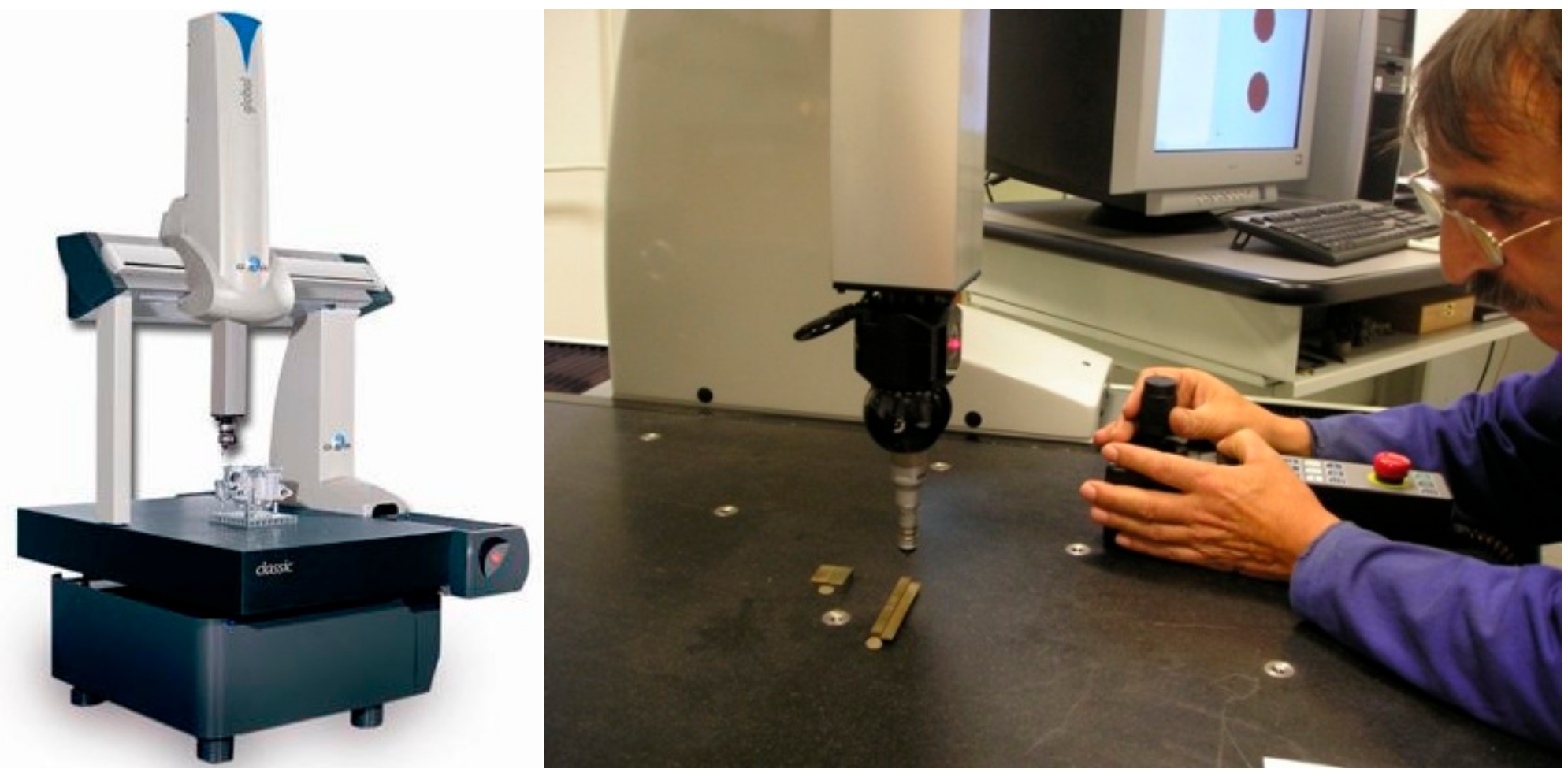
  55. DAE Global Classic. Available online: http://www.hexagonmetrology.fr/eng/GLOBAL-Classic_119.htm (accessed on 25 August 2017).
Figure 1. Identification of the geometric deviation of the shape of the machined surface.
Metals 07 00462 g001
Figure 2. The theoretical flatness deviation of the machined surface after WEDM roughing (full cut) with the wire electrode pre-tension Fw ≤ 5.0 N a Fw ≥ 10.0 N.
Metals 07 00462 g002
Figure 3. The theoretical flatness deviation of the machined surface after WEDM finishing (offset cut) with the wire electrode pre-tension Fw ≤ 5.0 N a Fw ≥ 10.0 N.
Metals 07 00462 g003
Figure 4. Tempering diagram of high-alloyed W+Cr+V tool steel EN X30WCrV9-3 [47].
Metals 07 00462 g004
Figure 5. CNC electrical discharge device Sodic AQ 535L.
Metals 07 00462 g005
Figure 6. Identifying the boundary points of the assessed eroded surface of prepared experimental sample on the table of measuring device a DAE Global Classic.
Metals 07 00462 g006
Figure 7. Determination of the scheme and the size of spacings t1 and t2 of the individual check points for the measurement of the flatness of the eroded area on the experimental sample from tool steel EN X30WCrV9-3.
Metals 07 00462 g007
Figure 8. Identification of flatness deviations of the eroded area of the experimental sample from tool steel EN X30WCrV9-3 using 3D coordinate measuring device DAE Global Classic.
Metals 07 00462 g008
Figure 9. Record from the identification of flatness deviations of the eroded area of the experimental sample from tool steel EN X30WCrV9-3 with dimensions 10.0 × 30.0 mm and length L = 40.0 mm in program PC-DMIS CAD 3.7.
Metals 07 00462 g009
Figure 10. Dependence of the flatness deviation ΔfR of the eroded surface from tool steel EN X30WCrV9-3 after WEDM roughing on length L ranging from 20.0 to 100.0 mm.
Metals 07 00462 g010
Figure 11. Dependence of the flatness deviation ΔfSF of the eroded surface of tool steel EN X30WCrV9-3 after WEDM semi-finishing in its dependence on length L in the range from 20.0–100.0 mm.
Metals 07 00462 g011
Figure 12. Dependence of the flatness deviation ΔfF of the eroded surface of tool steel EN X30WCrV9-3 after WEDM finishing in its dependence on length L in the range from 20.0 to 100.0 mm
Metals 07 00462 g012
Figure 13. Dependence of the maximum flatness deviation Δfmax of eroded surface of tool steel EN X30WCrV9-3 after WEDM roughing, semi-finishing and finishing with CuZn37 wire electrode of 0.20 mm diameter on the sample lengths L in the range from 5.0–50.0 mm.
Metals 07 00462 g013
Table 1. Causes of geometric deviations of the shape of the machined surface after WEDM.
Causes of Geometric Deviations of the Shape of the Machined Surface after WEDM
Related to the MachineRelated to the ToolRelated to the Workpiece
-
geometric and kinematic inaccuracies of the machine,
-
elastic deformations of the technological system,
-
insufficient machine alignment,
-
thermal deformations of the technological system,
-
vibration of the technological system,
-
erroneous software control of the technological system,
-
improper choice of process parameters.
-
mechanical deformation of the wire electrode,
-
improper mechanical, physical and chemical properties of the wire electrode,
-
vibration of the wire electrode.
-
erroneous clamping of the workpiece,
-
deformation of the workpiece due to clamping forces,
-
deformation of the workpiece due to internal stresses in the material,
-
non-homogeneity of the structure of the machined material.
Table 2. Theoretically achievable maximum range of geometric deviations of machined surface after WEDM with application of different machine power modes.
WEDM ModeRange of Geometrical Accuracy of Machined Surface
high-performance machining mode (roughing)±10.0 to ±50.0 μm
standard machining mode (semi-finishing)±5.0 to ±20.0 μm
precise machining mode (finishing)±2.0 to ±10.0 μm
electrical discharge polishing mode±1.0 to ±5.0 μm
Table 3. Chemical composition and selected mechanical and physical properties of tool steel EN X30WCrV9-3 (W.-Nr. 1.2581) [47,48].
Chemical Composition of Tool Steel EN X30WCrV9-3 (W.-Nr. 1.2581)
CMnSiCrWVPmaxSmax
0.25–0.35%0.2–0.4%0.15–0.3%2.5–2.8%8.0–9.0%0.3–0.4%0.35%0.35%
Selected Mechanical and Physical Properties of Tool Steel EN X30WCrV9-3 (W.-Nr.1.2581)
Tensile strength, Rm (MPa) (in natural state)Yield strength, Rp0,2 (MPa) (in natural state)Thermal conductivity W/(m.K) (at 20 °C)Specific heat capacity J/(kg·K)Specific electric resistance Ω.mm2/mElectrical conductivity Siemens.m/mm2Modulus of elasticity E GPaAchievable hardness after refining HRC
780670274600.521.95190–21052
Table 4. Basic mechanical, physical and chemical properties of the material of the coated wire electrode EN CW508L (W.-Nr. 2.0321).
Coated Wire Electrode EN CW508L (W.-Nr. 2. 0321)
Mechanical propertiesTensile Strength Rm [MPa]Yield Strength Rp0.2 [MPa]Proof Stress [MPa]Hardness HVElastic modulus E [GPa]Elongation A50 [%]Grain [mm]
300–550≤130110–50055–18010538–30.015–0.07
Physical propertiesElectrical conduction [%IACS]Electrical resistivity [μΩ·m]Melting point range [°C]Thermal conduction λ[W·m−1·K−1]Density ρ[kg·m³]Specific heat capacity cp 20 °C [J·kg−1·K−1]Coefficient of thermal expansion α 20 °C [10−6·K−1]
≥260.066902–920116845038021
Chemical compositionCuAlFeNiPbSnZn
62–64%<0.05%<0.1%<0.3%<0.1%<0.1%balance

