Article

Investigating the Wear Behavior of Fe-Based Amorphous Coatings under Nanoscratch Tests

School of Materials Science and Engineering, Tongji University, Shanghai 201804, China
*
Author to whom correspondence should be addressed.
Metals 2017, 7(4), 118; https://doi.org/10.3390/met7040118
Submission received: 23 January 2017 / Revised: 23 March 2017 / Accepted: 24 March 2017 / Published: 29 March 2017
(This article belongs to the Special Issue High-Entropy Alloys (HEAs))

Abstract

:
The wear behavior of two coatings (Fe49.7Cr18Mn1.9Mo7.4W1.6B15.2C3.8Si2.4 and Fe40Cr23Mo14C15B6Y2) sprayed by high-velocity air fuel technology was investigated through nanoscratch tests under ramping loads. Compared with the substrate, the Fe-based amorphous coatings exhibit lower penetration depth, higher elastic recovery, and lower wear volume, indicating the excellent wear resistance of the coatings. This behavior is related to the high hardness and high hardness/elastic modulus ratio (H/E) of the Fe-based amorphous coatings. From the scanning electron microscopy images of the scratch grooves, it is found out that ploughing governs the wear behavior of the coatings and substrate. In addition, spalling wear easily occurs in the pore regions of the coatings.

1. Introduction

Fe-based bulk metallic glasses (BMGs) have attracted a great deal of attention in the last few decades because of their low material cost and outstanding properties, such as high strength, high hardness, and excellent corrosion resistance [1,2,3,4,5]. Previous studies have reported that Fe-based BMGs have higher wear resistance than traditional crystalline steel [6] and many other metallic glass systems (such as Ni-based, Zr-based, and Cu-based systems) [7,8]. However, the brittleness of Fe-based BMGs at room temperature limits their application as structural materials. Due to the developments of BMG systems with great glass forming ability (GFA) and spraying technology, fabricating Fe-based amorphous coatings has now become available, which can effectively expand the application domain of Fe-based amorphous alloys. Amorphous alloy coatings avoid the drawback of the brittleness of Fe-based BMGs, and at the same time maintain their excellent mechanical and chemical performances [9,10]. Notably, Fe-based amorphous coatings have already exhibited higher hardness and better corrosion resistance than electroplated Cr and 304 stainless steel in an NaCl solution, demonstrating their great potential in applications on sail cover plates, ship hulls, decks of aircraft carriers, and other items that contact with sea water [11,12,13]. Fe-based amorphous coatings also possess outstanding wear resistance [14,15,16,17,18,19]. However, the wear behaviors of amorphous alloys are diverse in various test conditions, and the mechanism of abrasive wear of amorphous alloys, particularly coatings, is still inconclusive [18,19].
Presently, the nanoscratch test has become a simple, versatile, and rapid method of assessing scratch wear resistance and investigate modes of deformation and fracture in thin films and bulk materials. Hodge and Nieh used the nanoscratch technique to investigate the abrasive wear behavior of six amorphous alloys (Zr-based and Pd-based) [20]. They found that the wear resistance of the investigated amorphous alloys does not follow the classical Archard equation, that is, the wear resistance is not linearly proportional to hardness. As a relatively newly developed technique, the nanoscratch test has been used in the investigation of several other bulk amorphous alloys [21,22,23], such as Ce-based, Ti-based, etc. However, the nanoscratch behavior of amorphous coating has not been yet reported. Amorphous coatings possess oxides, pores, and other inhomogeneous phases, which may result in more complicated behavior than BMG.
In this study, high-velocity air fuel (HVAF) technology was used to prepare dense Fe-based amorphous coatings with low oxidation and high bonding strength. The HVAF technique utilizes air as combustion-supporting gas instead of oxygen in high-velocity oxygen fuel, thus providing a low temperature in the combustion chamber. Powders were injected into the combustion chamber where they were heated and then accelerated in a de Laval nozzle to a velocity >1000 m/s. Upon contact with the substrate, thermally softened particles undergo intensive plastic deformation and form a dense coating. We applied the nanoscratch test to investigate the wear behavior of Fe-based amorphous coatings, in order to throw new light on the wear mechanism of amorphous coatings.

2. Experimental Details

2.1. Fabrication of Amorphous Coatings

Two coatings with nominal chemical compositions of Fe49.7Cr18Mn1.9Mo7.4W1.6B15.2C3.8Si2.4 and Fe40Cr23Mo14C15B6Y2 were fabricated and investigated in this study. These coatings were denoted as Coating A and Coating B, respectively. As a comparison, the nanoscratch behavior of the substrate (304 stainless steel), denoted hereafter as 304, was also investigated. The powders used for spraying were prepared by high-pressure gas atomization method, with a cooling rate of ~104 K/s. The size of the powders used for spraying was less than 45 μm. Before spraying, the powders were heat-treated in an oven at 60 °C for 1 h to remove moisture. AcuKote HVAF spraying system was used both for gritblasting (brown corundum sand #150) and spraying. Powders were heated and accelerated by a high-velocity jet of combustion products of compressed air and fuel gas. Propane is used as the major fuel gas. The same parameters were utilized in gritblasting and spraying processes, as presented in Table 1.

2.2. Experiments

The structure of the coating samples were characterized by RIGAKU D/max2550VB3+/PC X-ray diffraction (XRD, Rigaku International Corporation, Tokyo, Japan) using Cu Kα radiation with 2θ diffraction angle ranging from 10° to 90° and a scanning speed of 5°/min. The thermal behaviors were detected by MDSC-Q100 differential scanning calorimeter (DSC, TA, New Castle, DE, USA) at a rate of 20 K/min from room temperature to 1273 K under argon atmosphere. The microstructure of powders and cross-sectional structure profile of as-sprayed coatings were observed by Quanta 200 FEG scanning electron microscopy (SEM, FEI Company, Hillsboro, OR, USA) with energy dispersive spectroscopy (EDS, FEI Company, Hillsboro, OR, USA).
All the samples were mechanically polished to a mirror finish for the nanoindentation and nanoscratch tests, which were conducted on the Nano Indenter G200 instrument (Agilent Technologies Inc., Santa Clara, CA, USA) equipped with the extensively used Berkovich indenter (Agilent Technologies Inc., Santa Clara, CA, USA) with a half-included angle of 72.8° at room temperature. The nanoindentation measurements were conducted in sets of 20 indents with a maximum load of 300 mN and a loading rate of 3 mN/s. For each nanoscratch test, three procedures were conducted in the following order: pre-scratching, during-scratching, and post-scratching. During the pre-scratching and post-scratching tests, a small constant load of 20 μN was applied to scan the surface profile. The during-scratching test was conducted under ramping loads from 0 mN to 100 mN at a speed of 10 μm/s. The length of all the scratches was 200 μm. At a load of 50 mN, the cross-profile of the scratch was measured. The difference between the indenter displacements of pre-scratching (Dpre) and during-scratching (Dduring) indicates the elastic/plastic deformation and surface damage. The difference between the indenter displacements of post-scratching (Dpost) and pre-scratching indicates the residual depth, thereby reflecting the wear volume. The difference between Dduring and Dpost represents the elastic recovery of the material. After the scratching tests, the wear tracks were observed using SEM.

3. Results and Discussion

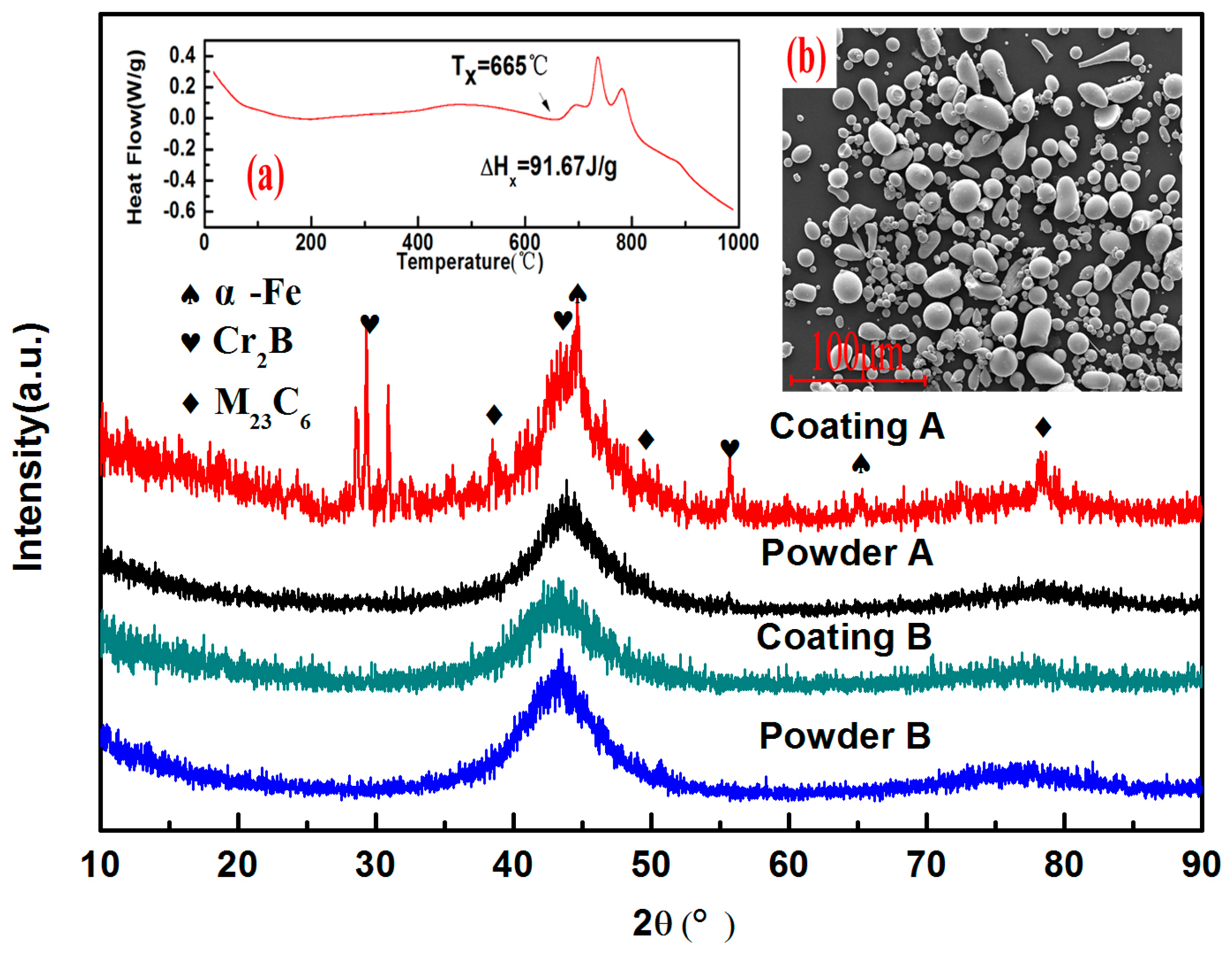
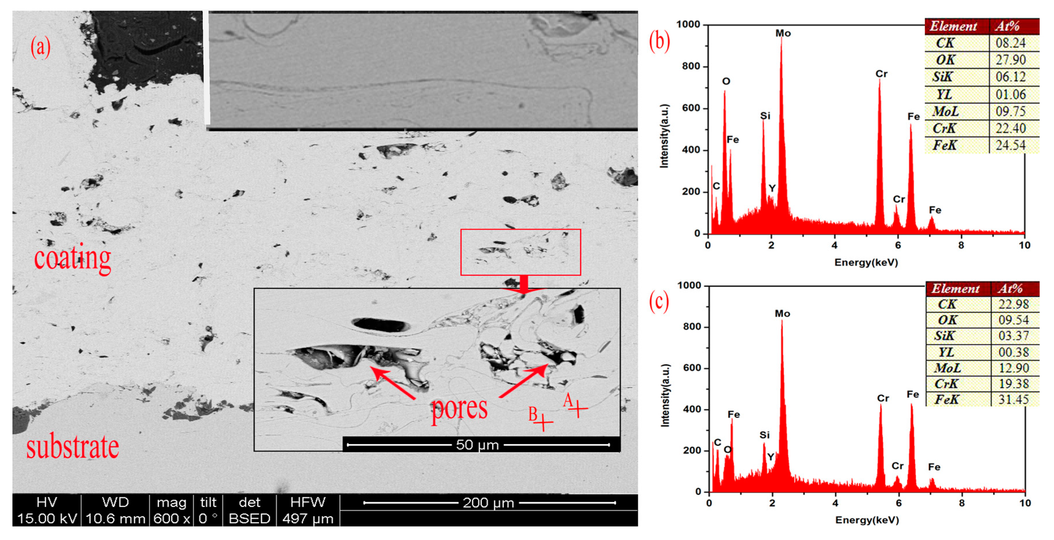
3.1. Structure of the Coatings
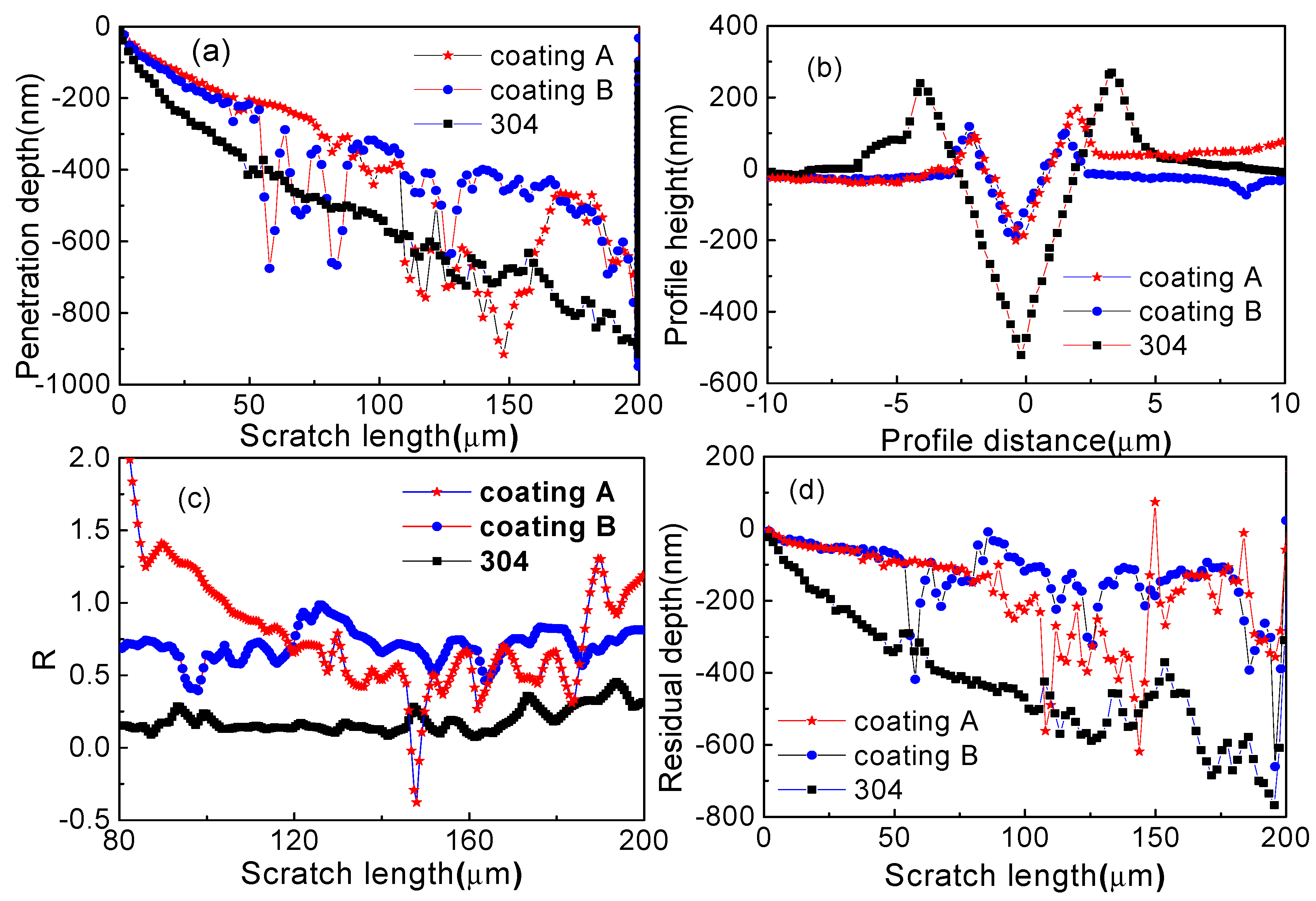
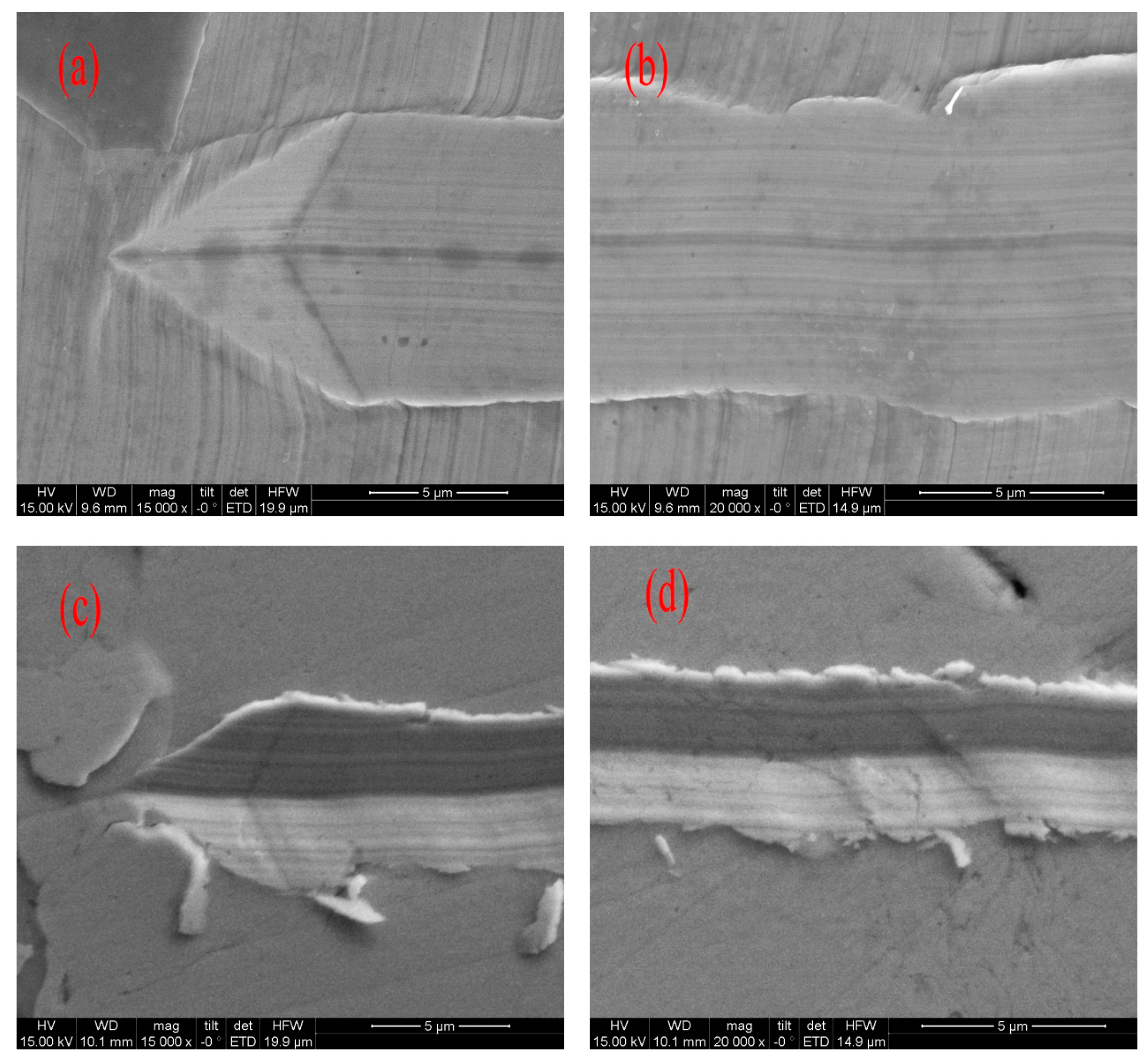
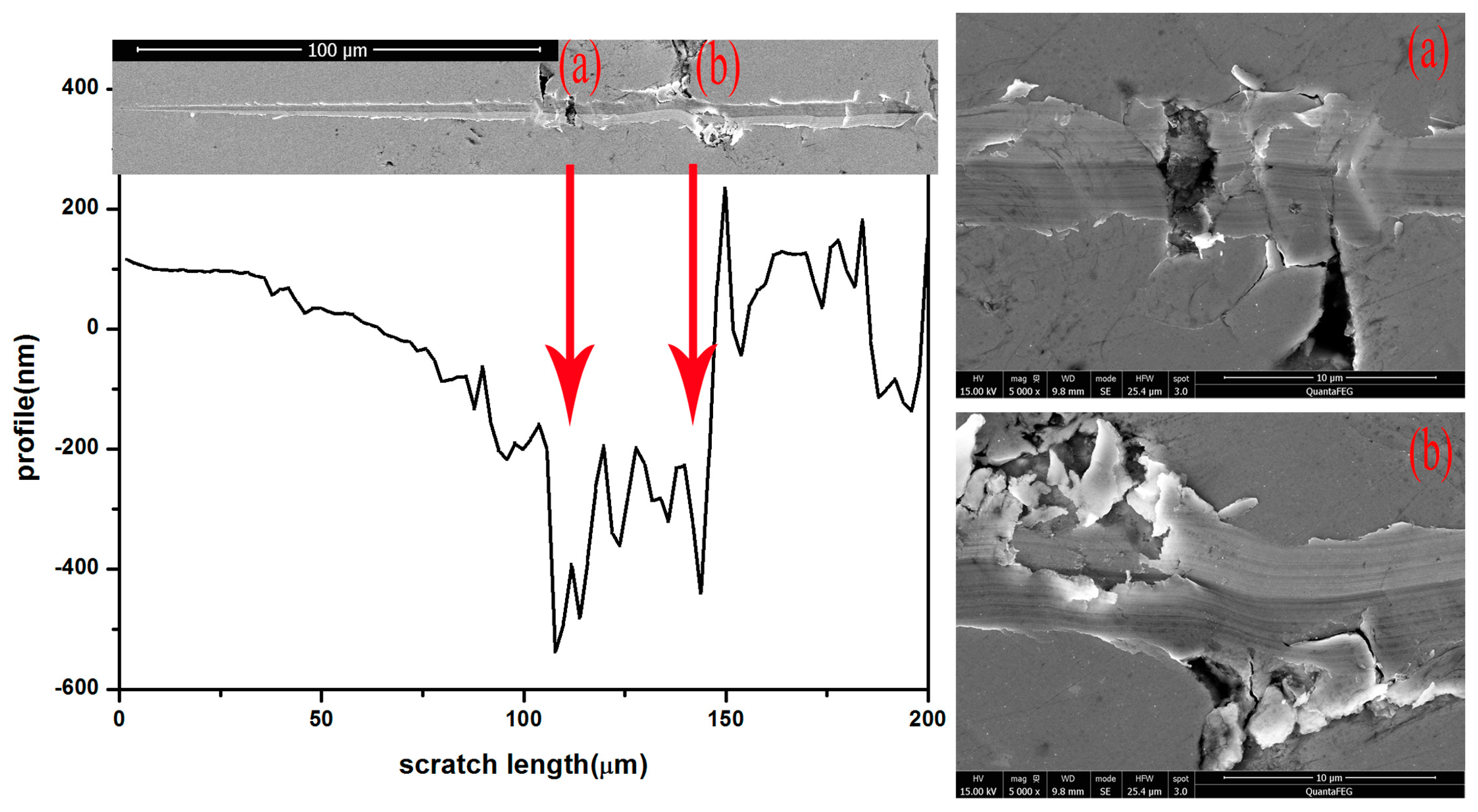
XRD patterns of the sprayed powders (A and B) in Figure 1 exhibit only a broad diffraction without peaks, indicating the high amorphous degree of powders. The inset (b) shows the SEM image of Powder B. Most of the particles are spherical or near-spherical with the diameter less than 45 μm, suggesting good fluidity of the powders. Figure 1 also shows the XRD patterns of the as-sprayed coatings. The XRD pattern of Coating B exhibits a broad diffraction maximum around 2θ ~ 44°. No sharp Bragg diffraction peak can be observed, which indicates a fully amorphous structure of the coating. From the DSC curve of Coating B (inset (a)), three continuous exothermic peaks with an onset crystallization temperature of 655 °C are observed. This indicates the complicated crystallization process and allows for an adjustment of the properties by heat treatment in a large temperature window. However, the pattern of Coating A reflects several Bragg diffraction peaks in the diffraction curve. This indicates a composite structure of the coating with a few crystalline phases embedded in the amorphous matrix [24]. The crystalline phases in Coating A are determined to be Cr2B, M23C6, and α-Fe [25], identified in Figure 1 with some unknown peaks.
The cross-sectional microstructure of Coating B is shown in Figure 2a (Coating A has similar structure, not shown here). The bottom of the photograph is the substrate, above which is the coating. The coating with a thickness of approximately 300 μm exhibits a dense structure. The inset is the enlarged image of the region denoted by a red rectangle, which shows the lamellar structure of the coating (see also the upper inset of Figure 2a). Energy-dispersive X-ray spectroscopy analysis of Point A (black bar region) and Point B (amorphous matrix), denoted by crosses, is shown in Figure 2b,c. A comparison of the two figures indicates that the black bars between two layers of coating are enriched with oxygen. The black bars are formed because of oxidation in the periphery of flying molten particles. With the deposition of the particles, the oxide layers interconnect to form the black bars called intersplats [26]. Some pores (oval-shaped or irregularly shaped) intersperse in Coating B, as can be seen in Figure 2a. The formation of pores can be primarily attributed to (1) the incomplete deformation of particles, which makes the seamless connection of particles impossible; and (2) the volume shrinkage of the particles when cooling down to room temperature [9].

3.2. Wear Behavior

Figure 3a shows the penetration depth (DduringDpre) of the three samples scratched with ramping loads from 0 mN to 100 mN as a function of scratch length. The penetration depth of the three samples increases with the increase of scratch length (load). Compared with 304, the curves of the coatings are more undulating, exhibiting several ‘valleys’ (e.g., see the scratch length range from 100 μm to 150 μm in Coating A). The sudden increase in penetration depth is due to the inhomogeneity of the structure, such as the existence of pores, which will be discussed in the subsequent sections. Apart from the aforementioned ‘valleys’, the other parts of the coating, namely, the homogeneous amorphous regions, show a smaller penetration depth than 304 (the two coatings have similar values). This phenomenon is also observed in the cross profiles of the scratch shown in Figure 3b (measured at a load of 50 mN), in which 304 possesses the maximum penetration depth of approximately 500 nm. While Coatings A and B both have a much smaller penetration depth of ~200 nm, indicating their greater hardness. Hardness is usually regarded to have a predominant role in the wear resistance of many materials [27,28,29,30]. In addition, there is strong evidence to suggest that the elastic modulus (especially the elastic strain to failure, which is related to H/E) can also have an important influence on the wear behavior [31]. Table 2 lists the hardness and elastic modulus of each sample obtained from the nanoindentation tests (typical curves are shown in Figure 4a). The coatings have a greater hardness and higher H/E value than does 304. As an important index of wear resistance, penetration depth depends strongly on hardness and H/E, which is to say that a greater hardness or higher H/E value leads to a lower penetration depth of the coatings, which agrees with other publications [20,22,31].
The difference between Dduring and Dpost reflects the elastic recovery of the material. An index R is defined, where R = (DduringDpost)/Dduring, to denote the elastic recovery more accurately [11]. Figure 3c shows R as a function of the scratch length of the three samples. The coatings exhibit greater elastic recovery than does 304, as observed from Figure 3c. Elastic recovery has been reported to be related to H/E and increases consistently with the increase in H/E [1]. As listed in Table 1, the H/E of Coating A, Coating B, and 304 were determined to be 0.07158, 0.07611, and 0.02512, respectively. The coatings have a similar H/E, which is higher than that of 304, thereby reflecting their elastic recovery difference.
Figure 3d shows the residual depth (DpostDpre) of the three samples as a function of scratch length, and we can measure the wear volume by using the following equation [11]:
V = 0 x d V = 0 x h x 2 t g θ d x
where x is the scratch length and hx is the residual depth at scratch length x. Figure 4 shows the wear volume as a function of scratch length for Coating A, Coating B, and 304. The wear volume of 304 is greater than that of the coatings. When the scratch length is <110 μm, the wear volumes of the two coatings are similar. However, Coating A exhibits a greater wear volume than Coating B when the scratch length is >110 μm, which may be due to the existence of more pores on the scratch tracks. As such, we can infer that the wear resistance of the coatings is better than that of 304. By fitting the wear volume curves, we can easily observe that the wear volume of 304 increases with the increase in scratch length in parabolic form. This finding is consistent with the modified Archard wear equation for a ramping load [20], expressed as follows:
V = 40Kx2/H
where x is the scratch length, H is the hardness, and K is the dimensionless wear coefficient. However, we found that this law cannot well describe the wear volume curves of the present coatings, which may be due to these coatings’ nonuniform structures.
The samples were examined via SEM after scratching to determine the scratch-forming mechanism. Figure 5 shows the SEM images of the worn surface of the three samples. The arrow indicates the scratch direction, along which the grooves become wider as the load increases. By comparing the three marks, we observed that they all exhibit pile-ups along the edge of grooves, which are also shown in Figure 3b. Thus, we can deduce that the ploughing mechanism occurred in all the three samples. Nevertheless, 304 exhibits a clean and uniform appearance with little debris, whereas the coatings exhibit a smeared appearance with numerous debris along the edge of the grooves. The details of the scratch marks of 304 and Coating A shown in Figure 6 reveal the difference of the scratch mechanism between substrate and coating. In contrast to the substrate that possesses smooth edges, Coating A possesses rough and ragged edges with several fragments that deviate from them. Considering the brittleness and stress concentration in the pores of coatings, we can infer that, when the indenter is indented in the surface, some cracks will generate in pore regions or other defective regions. With the indenter scratching across the material, the cracks will propagate along the intersplats because of their lower bonding strength. If the stress intensity factor K is close to KIC, then cracks will propagate unsteadily, thereby leading to the spalling of the flat particles from the coating. When cracks expand between particles, the particles above the cracks, like cantilever beams, will break under pressure. Therefore, the presence of fragments indicates that spalling wear also occurs in coatings.
The worn surfaces have different morphologies in different regions because of the inhomogeneity of the structure of coatings. Figure 7 shows a comparison of the post-scratch profile and SEM image of Coating A. Two “valleys” in the post-scratch profile are inferred to correspond to Regions (a) and (b) shown in the SEM image. These two “valleys” exhibit different morphologies from other regions of the scratch marks. Pores and numerous debris can be observed in the enlarged images shown in Figure 7a,b. In the pore regions, crack initiation is easier than in other compact regions. As such, spalling wear will easily occur in the pore regions, which is relevant to the decrease in wear resistance.

4. Conclusions

Two Fe-based amorphous coatings were fabricated using the HVAF system. The wear behavior of the amorphous coatings and substrate was investigated through nanoscratch tests. The main conclusions are as follows:
  • The two Fe-based amorphous coatings have better wear resistance than the 304 stainless steel substrate, as indicated by the lower penetration depth, higher elastic recovery, and lower wear volume, which is related to their higher hardness and H/E values. The present results validate that the HVAF-sprayed Fe-based amorphous coatings have great potential for applications in areas that involve high wear, such as power stations, drilling, and machinery.
  • The scratch mechanism of ploughing occurs in both the coatings and substrate. In addition, spalling wear is associated with crack initiation and propagation that occur in Fe-based amorphous coatings but not in the substrate. Furthermore, we determined that the modified Archard wear equation cannot be used to describe the scratch length dependence of the wear volume of present coatings.
  • Spalling wear can easily occur in the pore regions, thereby decreasing wear resistance. Optimizing the spraying processes to fabricate coatings with less porosity can improve the wear resistance.

Acknowledgments

This work is financially supported by the National Natural Science Foundation of China (grant nos. 51371127, 51601130 and 51601129) and the Shanghai Natural Science Foundation (grant no. 13ZR1462400).

Author Contributions

Y.W. and Q.L. conceived and designed the experiments; Y.W. performed the experiments; J.J. and X.W. and J.S. contributed sample fabrication; Y.W. and Q.L. and J.S. wrote the paper. All authors contributed to data analysis and discussion.

Conflicts of Interest

The authors declare no conflict of interest.

References

  1. Inoue, A. Stabilization of metallic supercooled liquid and bulk amorphous alloys. Acta Mater. 2000, 48, 279–306. [Google Scholar] [CrossRef]
  2. Pang, S.J.; Zhang, T.; Asami, K.; Inoue, A. Synthesis of Fe–Cr–Mo–C–B–P bulk metallic glasses with high corrosion resistance. Acta Mater. 2002, 50, 489–497. [Google Scholar] [CrossRef]
  3. Löffler, J.F. Bulk metallic glasses. Intermetallics 2003, 11, 529–540. [Google Scholar]
  4. Inoue, A.; Takeuchi, A. Recent development and application products of bulk glassy alloys. Acta Mater. 2011, 59, 2243–2267. [Google Scholar] [CrossRef]
  5. Gu, X.J.; Poon, S.J.; Shiflet, G.J. Mechanical properties of iron-based bulk metallic glasses. J. Mater. Res. 2007, 22, 344–351. [Google Scholar] [CrossRef]
  6. Huang, D.; Li, R.; Huang, L.; Ji, V.; Zhang, T. Fretting wear behavior of bulk amorphous steel. Intermetallics 2011, 19, 1385–1389. [Google Scholar] [CrossRef]
  7. Inoue, A.; Wang, X.M.; Zhang, W. Developments and applications of bulk metallic glasses. Rev. Adv. Mater. Sci. 2008, 18, 1–9. [Google Scholar]
  8. Togashi, M.I.N.; Nishiyama, N.; Inoue, A. Wear resistance of metallic glass bearings. Rev. Adv. Mater. Sci. 2008, 18, 93–97. [Google Scholar]
  9. Liu, L.; Zhang, C. Fe-based amorphous coatings: Structures and properties. Thin Solid Films 2014, 561, 70–86. [Google Scholar] [CrossRef]
  10. Bolelli, G.; Bonferroni, B.; Laurila, J.; Lusvarghi, L.; Milanti, A.; Niemi, K.; Vuoristo, P. Micromechanical properties and sliding wear behaviour of HVOF-sprayed Fe-based alloy coatings. Wear 2012, 276–277, 29–47. [Google Scholar] [CrossRef]
  11. Farmer, J.; Payer, J.; Branagan, D.; Beardsley, B.; D’amato, A.; Aprigliano, L.; Choi, J.-S.; Saw, C.; Haslam, J.; Day, D.; et al. Iron-Based Amorphous Metals: High-performance corrosion-resistant material development. Metall. Mater. Trans. A 2009, 40, 1289–1305. [Google Scholar] [CrossRef]
  12. Farmer, J.C.; Haslam, J.J.; Day, S.D.; Lian, T.; Saw, C.K.; Hailey, P.D.; Choi, J.S.; Rebak, R.B.; Yang, N.; Payer, J.H.; et al. Corrosion resistance of thermally sprayed high-boron iron-based amorphous-metal coatings: Fe49.7Cr17.7Mn1.9Mo7.4W1.6B15.2C3.8Si2.4. J. Mater. Res. 2007, 22, 2297–2311. [Google Scholar] [CrossRef]
  13. Guo, R.Q.; Zhang, C.; Yang, Y.; Peng, Y.; Liu, L. Corrosion and wear resistance of a Fe-based amorphous coating in underground environment. Intermetallics 2012, 30, 94–99. [Google Scholar] [CrossRef]
  14. Cheng, J.; Liang, X.; Xu, B.; Wu, Y. Microstructure and wear behavior of FeBSiNbCr metallic glass coatings. J. Mater. Sci. Technol. 2009, 25, 687–690. [Google Scholar]
  15. Zhou, Z.; Wang, L.; He, D.Y.; Wang, F.C.; Liu, Y.B. Microstructure and wear resistance of Fe-based amorphous metallic coatings prepared by HVOF thermal spraying. J. Therm. Spray Technol. 2010, 19, 1287–1293. [Google Scholar]
  16. Zhang, C.; Liu, L.; Chan, K.C.; Chen, Q.; Tang, C.Y. Wear behavior of HVOF-sprayed Fe-based amorphous coatings. Intermetallics 2012, 29, 80–85. [Google Scholar]
  17. Wong, C.J.; Li, J.C.M. Wear behavior of an amorphous alloy. Wear 1984, 98, 45–61. [Google Scholar] [CrossRef]
  18. Duan, H.; Wu, Y.; Meng, H.; Wang, J.; Tu, J.; Kou, H.; Li, Y.; Zhang, T.; Li, J. Tribological properties of Zr41.25Ti13.75Ni10Cu12.5Be22.5 bulk metallic glasses under different conditions. J. Alloys Compd. 2012, 528, 74–78. [Google Scholar] [CrossRef]
  19. Prakash, B. Abrasive wear behaviour of Fe, Co and Ni based metallic glasses. Wear 2005, 258, 217–224. [Google Scholar] [CrossRef]
  20. Hodge, A.M.; Nieh, T.G. Evaluating abrasive wear of amorphous alloys using nanoscratch technique. Intermetallics 2004, 12, 741–748. [Google Scholar] [CrossRef]
  21. Wang, J.G.; Choi, B.W.; Nieh, T.G.; Liu, C.T. Nano-scratch behavior of a bulk Zr-10Al-5Ti-17.9Cu-14.6Ni amorphous alloy. J. Mater. Res. 2000, 15, 913–922. [Google Scholar] [CrossRef]
  22. Huang, Y.; Chiu, Y.L.; Shen, J.; Sun, Y.; Chen, J.J.J. Mechanical performance of metallic glasses during nanoscratch tests. Intermetallics 2010, 18, 1056–1061. [Google Scholar]
  23. Han, D.X.; Wang, G.; Li, J.; Chan, K.C.; To, S.; Wu, F.F.; Gao, Y.L.; Zhai, Q.J. Cutting characteristics of Zr-based bulk metallic glass. J. Mater. Sci. Technol. 2015, 31, 153–158. [Google Scholar] [CrossRef]
  24. Wang, A.P.; Wang, Z.M.; Zhang, J.; Wang, J.Q. Deposition of HVAF-sprayed Ni-based amorphous metallic coatings. J. Alloys Compd. 2007, 440, 225–228. [Google Scholar] [CrossRef]
  25. Farmer, J.; Day, D.; Lian, T.; Saw, C.; Hailey, P.; Payer, J.; Aprigliano, L.; Beardsley, B.; Branagan, D. Long-term corrosion testing of thermal spray coatings of amorphous metals: Fe49.7Cr17.7Mn1.9Mo7.4W1.6B15.2C3.8Si2.4 and Fe48Mo14Cr15Y2C15B6. In Proceedings of the Materials Science & Technology 2007 Conference and Exhibition, Detroit, MI, USA, 16–20 September 2007. [Google Scholar]
  26. Guo, W.; Wu, Y.; Zhang, J.; Hong, S.; Li, G.; Ying, G.; Guo, J.; Qin, Y. Fabrication and characterization of thermal-sprayed Fe-based amorphous/nanocrystalline composite coatings: An overview. J. Therm. Spray Technol. 2014, 23, 1157–1180. [Google Scholar] [CrossRef]
  27. Archard, J.F. Contact and rubbing of flat surfaces. J. Appl. Phys. 1953, 24, 981–988. [Google Scholar]
  28. Wen, S.P.; Zong, R.L.; Zeng, F.; Gao, Y.; Pan, F. Investigation of the wear behaviors of Ag/Cu multilayers by nanoscratch. Wear 2008, 265, 1808–1813. [Google Scholar] [CrossRef]
  29. Wen, S.P.; Zong, R.L.; Zeng, F.; Guo, S.; Pan, F. Nanoindentation and nanoscratch behaviors of Ag/Ni multilayers. Appl. Surf. Sci. 2009, 255, 4558–4562. [Google Scholar] [CrossRef]
  30. Lawn, B.R.; Howes, V.R. Elastic recovery at hardness indentations. J. Mater. Sci. 1981, 16, 2745–2752. [Google Scholar] [CrossRef]
  31. Leyland, A.; Matthews, A. On the significance of the H/E ratio in wear control: A nanocomposite coating approach to optimised tribological behaviour. Wear 2000, 246, 1–11. [Google Scholar]
Figure 1. X-ray diffraction (XRD) patterns of sprayed powders and coatings with the insets showing the DSC curve of Coating B (a) and morphology of Powder B (b).
Metals 07 00118 g001
Figure 2. Cross-sectional microstructure of Coating B (a) and EDX analysis of Point A (b) and Point B (c).
Metals 07 00118 g002
Figure 3. Penetration depth (a); profile height (b); elastic recovery R (c); and residual depth (d) of the three samples.
Metals 07 00118 g003
Figure 4. (a) Typical nanoindentation curves of the samples; (b) Wear volume of the three samples as a function of scratch length and fitted line of 304.
Metals 07 00118 g004
Figure 5. Scanning electron microscopy (SEM) images of the worn surface of the three samples: (a) 304; (b) Coating B; (c) Coating A.
Metals 07 00118 g005
Figure 6. Enlarged SEM images of the samples: (a,b) 304 and (c,d) Coating A.
Metals 07 00118 g006
Figure 7. Comparison of the post-scratch profile and SEM image of Coating A, and the enlarged SEM images of regions (a) and (b).
Metals 07 00118 g007
Table 1. Spraying and gritblasting parameters employed in the high-velocity air fuel (HVAF) process.
ParameterCondition
Nozzle#1L (Laval nozzle with length of 100 mm)
Air flow, PSI74.8
Fuel flow, PSI70.3
Spraying distance, mm180
Table 2. Surface hardness (H), elastic modulus (E), and H/E values of all samples under a load of 300 mN.
SamplesHardness, GPaElastic Modulus, GPaH/E
3044.668 ± 0.205185.845 ± 5.7460.02512
Coating A9.576 ± 3.008133.646 ± 33.7560.07158
Coating B11.327 ± 2.946148.831 ± 28.8660.07611

