Article

Rheological Characterization of Powder Mixture Including a Space Holder and Its Application to Metal Injection Molding

1
School of Mechanical Engineering, Pusan National University, Busan 46241, Korea
2
Department of Mechanical Engineering, Pohang University of Science and Technology, Pohang 37673, Korea
*
Author to whom correspondence should be addressed.
Metals 2017, 7(4), 120; https://doi.org/10.3390/met7040120
Submission received: 23 February 2017 / Revised: 28 March 2017 / Accepted: 28 March 2017 / Published: 30 March 2017

Abstract

:
Metal injection molding (MIM) with the space holder technique is becoming one of the important fabrication methods for a net-shape production of micro-sized, porous, complex-shaped metal parts. For a successful injection molding step, rheological behavior of MIM feedstock is essential, which includes peculiar characteristics, such as a wall slip phenomenon. SUS 316L stainless steel powder, binder systems (paraffin wax, polypropylene, polyethylene, stearic acid) and three different sizes of spherically-shaped polymethyl methacrylate (PMMA) as a space-holder were used for this study. The porosity was controlled by varying the volume fraction of the space holder and a total of six different feedstocks were prepared. Rheological characteristics of the feedstock was investigated, especially on viscosities, including wall slip quantification by using a capillary rheometer. By thermogravimetric analysis, the debinding process for completely removing the space holder was proposed. Finally, the shrinkage and porosity of the tensile specimen produced through the sintering process were analyzed and the ultimate tensile strength was obtained.

1. Introduction

Porous metals have useful properties, such as relatively low density, high strength to weight ratio, large specific surface area, high gas and liquid permeability, high thermal conductivity, and excellent energy absorption capacity. Due to these advantages, there are a variety of manufacturing methods of making micro-porous metal foam shapes, as mentioned in Manonukul et al. [1]. Porous structures can be classified as open porosity and closed porosity structures. For examples, a closed porous structure can be used in applications that require lightweight structural elements with better acoustical and impact energy absorption. Open porous structures can also be used for high-performance applications, such as heat exchangers and heat sinks for thermal management, as well as medical implants, filters, and electrodes for biological and chemical reactions. The various beneficial characteristics of these materials and their manufacturing methods are listed by Heaney et al. [2]. One of the method is using a space holder material like NaF and NaCl in the hot isostatic pressing (HIP) process to achieve well-defined porosities and pore sizes. Although its mechanical properties are promising, the disadvantage of the method is that it is still a difficult shaping process after compaction and removal of the space holder. In order to overcome this drawback, MIM with the space holder technology has recently been proposed and applied by many researchers. MIM with the space holder technique can produce both open- and closed-cell complex shape metal parts. A typical MIM process is composed of four basic steps which are (1) mixing; (2) injection molding; (3) debinding; and (4) sintering processes [3]. For a successful injection molding step, analysis of the rheological properties of the feedstock is essential, and as a result, viscosity is one of the important parameters for process optimization. There are previous studies on MIM with the space-holder technique. Manonoukul et al. experimentally found a relationship between space holders and porosity of SUS 316L. They used polymethyl methacrylate (PMMA) for the space holder for its high rigidity, thermal resistance, non-reactiveness to metal powder, various size, and reasonable cost. They showed that PMMA did not blend with the binder system and found out that as the volume fraction of PMMA increased, the sintered density and mechanical properties decreased [1]. Several other studies cover various metals for MIM with the space holder technique, such as aluminum alloy [4], copper [5], stainless steel [6], and titanium alloy [7]. Köhl et al. studied the near-net-shape of NiTi shape memory alloys for use as a long-term implant by MIM with the space-holder technique. Their study showed that MIM is able to fabricate a porous NiTi implant in which strength is close to that of human bone. They investigated NaCl, saccharose, and PMMA as candidate materials for the space holder and concluded that NaCl is the most promising due to its low C- and O- impurity contents for NiTi implant application [8]. Gülsoy and German studied influence of the space holder (PMMA)’s volume fractions on both injection molding and sintering processes of austenitic stainless steel [9]. The effect of space holder (PMMA)’s particle size and the volume fraction on dimensional tolerance was studied by Nishiyabu et al. [7,10]. The result showed PMMA is easily removed during thermal debinding and also porous part with 30% and 60% volume fractions of PMMA were successfully produced. In our study, PMMA was chosen as a material for space holders for the same reason as in the Manonukul’s study: PMMA’s melting temperature is higher than those of the binder materials in our study, and of the mixing and injection temperatures, so its shape can be kept before the debinding process. Since the existing research focuses mainly on the feasibility of MIM for producing porous metal parts, in this study, the influence of the size and the volume ratio of the space-holder to the rheological characterization of the MIM feedstock (including quantification of the wall slip) for optimization of the injection molding process was studied.

2. Experimental Procedure

2.1. Materials

The metal powder used in this study is SUS 316L stainless steel powder (Epson Atmix Co., Aomori, Japan). The properties of the powder and binders are summarized in Table 1 and Table 2, and the binders are mainly of paraffin wax (PW), polypropylene (PP), polyethylene (PE), and stearic acid (SA). Polymethyl methacrylate (PMMA, Sunjin Beauty Science Co., Ansan, Korea) was used as a space holder and its characteristics are given in Table 3. Scanning electron microscope (Hitachi S3500N, Tokyo, Japan) photographs of powder, space holder, and mixtures are shown in Figure 1 and Figure 2. Both SUS 316L powder and PMMA space holder are spherical and have excellent flowability and packing density.

2.2. Mixing of Powder-Binder-Space Holder Feedstock

For a successful injection molding, homogenous mixing of powder and binder is essential. One significant factor affecting feedstock’s homogeneity is solid loading percentage. Solid loading percentage refers to the volume ratio of powder to powder-binder mixture. When powder is packed tightly and binder fills all the voids between the particles, it is called the critical solid loading state [11]. A torque rheometer (Haake PolyLab QC, Thermo Scientific Inc., Waltham, MA, USA) was used to measure the critical solid loading point for the feedstock used in this study. The powders and binder were mixed at an operating temperature of 150 °C and a rotational speed of 150 rpm. When the rpm was stabilized, the powder was added in such a manner that 1 vol % of the powder was further added. Solid loadings were increased gradually from 55 vol % to 66 vol % until the torque reading became unstable. Figure 3a shows the torque vs. time in minutes, where the torque increased with a solid loading and critical solid loading percent was found at 61 vol % for the feedstock by observing the slope change, as shown in Figure 3b. In general, the optimal solid loading is set 1% to 3% lower than the critical solid loading for process flexibility so optimal solid loading is set at 60 vol % in this study.
For the study of rheological properties, a twin-screw extruder-type mixer (CetaTech Inc., Sacheon, Korea) was used for feedstock mixing and pelletization. A twin-screw extruder is the most widely used mixer in the MIM industry for feedstock production. The average mixing temperature was set at 150 °C below PMMA’s melting temperature and the mixing speed was set at 30 rpm. To investigate the effect of size and volume fraction of PMMA on the rheological properties, six feedstocks were prepared and their composition is summarized in Table 4 and Table 5. The premixed powder-binder-space holder mixture was mixed with the twin-screw extruder. To ensure homogeneity of the feedstock, the mixing step was repeated three times.

3. Rheological Characterization of the Feedstock

3.1. Viscosity Measurements Using Capillary Rheometer

A uniform and complete filling of the mold during injection molding requires an understanding of the rheological properties of the viscous flow of the mixture, and viscosity is one of the most important required input parameters used in the CAE filling analysis of injection molding processes [11,12]. The viscosity of the feedstock in our study was measured by using a twin-bore barrel capillary rheometer (Rosand RH7, Malvern instruments Ltd., Malvern, UK). The measuring temperature was set at 150 °C, the same as in the mixing process. While the feedstock passes through the capillary die, the ram position, pressure, shear rate, shear stress, viscosity, and ram speed are measured. Three different diameter capillary measurement bores (ϕ 0.5 × 8 mm, ϕ 1 × 16 mm, ϕ 1.5 × 24 mm) with correction bores (ϕ 0.5 × 0.25 mm, ϕ 1 × 0.25 mm, ϕ 1.5 × 0.25 mm) were used to quantify the wall slip phenomenon. A capillary rheometer is widely used due to its relatively high shear rate performance (100–5000 L/s), which is close to the shear rate generated by the injection molding filling process. The result is viscosity vs. shear rate plots and will be discussed in the next section.

3.2. Modified Cross-WLF Model

One of the viscosity models representing the viscosity of the feedstock is the modified cross-WLF model as follows [13]:
η = η 0 1 + ( η 0 γ ˙ τ * ) 1 n
where η is viscosity of the feedstock, η 0 is zero shear viscosity, γ ˙ is shear rate, n is power law index, and τ * is critical stress level at the transition to shear thinning. The zero shear viscosity ( η 0 ) is given by the Equation (2):
η 0 = D 1 [ A 1 ( T T * ) A 2 + T T * ] ,   T * = D 2 + D 3 p ,   A 2 = A 2 ¯ + D 3 p
where T is temperature (K), T * is glass transition temperature, p is pressure (Pa) and D 1 , A 1 A 2 ¯ and D 3 are data fitting coefficients. In this study, the modified cross-WLF model was used as a viscosity model to express viscosity of the feedstock. For MIM feedstocks, the modified cross-WLF model is generally more suitable than the power-law model.

3.3. Results from Capillary Rheometer Experiements

3.3.1. Effect of PMMA Space Holder’s Size

To investigate the effect of size of PMMA space holder on viscosity, PMMA space holder diameters of 20 μm, 50 μm, and 80 μm were mixed with the powder and binder, respectively. SUS 316L:space holder:binder = 40:20:40 vol % was used for this study. Figure 4a shows viscosity vs. shear rates for different size space holders (F1 has no PMMA, F2 has 20 μm PMMA, F3 has 50 μm PMMA, F4 has 80 μm PMMA). The mixtures are showing shear-thinning fluid behavior. As can be seen in Figure 4, the viscosity of F2, F3, and F4 is lower than F1 because one third of the metal powder has been replaced by larger size PMMA space holders. It is also observed that the viscosity of the mixture decreases as the size of the space-holder increases and becomes less sensitive to the shear rate changes.

3.3.2. Effect of PMMA Space Holder’s Volume Fraction

In order to investigate the effect of volume ratio of PMMA space holder on viscosity, the diameter of PMMA space holder was fixed at 50 μm and the ratio of space holder was changed to 20 vol %, 30 vol %, and 40 vol %. In Figure 4b, the viscosity vs. shear rate for different PMMA volume fractions is shown. F1, F3, F5, and F6 are feedstocks with 0 vol % PMMA, 20 vol % PMMA, 30 vol % PMMA, and 40 vol % PMMA space holder. In early trials, it was concluded that the part containing 50 vol % PMMA remained barely in shape during debinding and sintering were not suitable for the experiment because the shrinkage was too high, the same as in Manonukul’s study [1]. It is observed that the viscosity of the mixture decreases as the volume fraction of the PMMA space holder increases and becomes less sensitive to the shear rate changes. From another point of view, a feedstock rich in metal powder is more viscous than a feedstock containing less. Comparing Figure 4a,b, it can be concluded that the variable more sensitive to viscosity change is the volume fraction of the space holder added to the mixture. This result is consistent with the previous rheological behavior study of a highly-filled suspension with varying particle size and volume fraction [13]. From this point of view, it can be concluded that the viscosity of the feedstock decreases as the particle size increases, even though two different sizes of particles (metal powder and space holder) are mixed as MIM feedstocks used in this study.

3.3.3. Slip Phenomena of Powder-Binder-Space Holder Mixtures

When a suspension fluid passes through a capillary die, slip may occur at the wall of the capillary where a solid-solid interface may occur. Without considering the slip phenomenon, the viscosity is eventually underestimated and a filling simulation based on viscosity without slip considerations results in misleading results. One of the models can describe the slip phenomenon as a slip velocity model, and the velocity profile of the fluid can change at the wall, as shown in Figure 5 [14].
As shown in Figure 5, if there is a slip velocity (Vs) at the wall, it can be measured using Mooney’s method and related equations can be written as follows [15]:
32 Q π D 3 =   4 τ w 3 0 τ w τ 2 γ ˙ d τ +   8 V s D
where Q is the flow rate, D is the diameter of the capillary rheometer, τw is the wall shear stress, τ is the shear stress, γ ˙ is the shear rate, and Vs is the slip velocity. Fixing τw as a constant and taking the partial derivative of Equation (3) by 1/D results in the slip velocity formula as follows [13]:
8 V s = ( 32 Q π D 3 ) ( 1 D ) τ w
Vs can be calculated by Equation (4) by using various diameter capillary dies from the capillary rheometer experiment. In this study, 0.5 mm, 1 mm, and 1.5 mm diameter capillary dies were used.
In Figure 6, the apparent shear rate vs. various 1/D at constant shear stress for F6 (SUS 316L:space holder:binder = 40:20:40 vol %, PMMA particle size = 50 μm) is given. The slip velocity at the given shear stress is the slope of the regression lines drawn from the data points. In Figure 7, the slip velocity versus shear stress (for different sizes and volume fractions of PMMA space holder) are given in terms of a power law and the related coefficients are summarized in Table 6.
From Figure 6 and Figure 7, it can be observed that the flow of powder-space holder-binder mixtures was strongly affected by slip at the wall. In Figure 7a, with 20 vol % of powder being replaced by 20 vol % of PMMA (F2, F3, F4) result increase in slip velocity about 7 to 9 times. Replacing 40 vol % of powder to 40 vol % PMMA (F6) showed a slip velocity increase of about 9 to 13 times in Figure 7b. It can also be observed that the slip velocity increases with increasing size of the diameter of the PMMA space holder and volume fractions.

4. Injection Molding, Debinding, and Sintering Processes

4.1. Injection Molding Process

To produce porous metal parts for this study, tensile specimens were prepared by injection molding (Engel Victory 80, Engel, Schwertberg, Austria) with the feedstocks, which was based on the results from the previous section. To maximize the porosity, different sizes of the PMMA space holder were mixed together at wt. % of 80 (80 μm):19.5 (50 μm):1.55 (20 μm) and finally feedstocks with PMMA space holder vol %, 0, 20, 30, and 40 were prepared. Tensile specimens were produced under the conditions given in Table 7.
In order to prevent the space holder from melting and retaining the shape during the injection molding, the injection temperature was set at 150 °C. Generally, PMMA decomposes above 200 °C. These shape-retained space holders help to develop porous characteristics in the specimen. The tensile specimen has a rectangular cross-section with the width of 8 mm and the thickness of 4 mm, a total length of 113 mm, and a gauge length is 55 mm. The cross-section of the green part was observed by SEM. It was confirmed from Figure 8 that the PMMA space holder is retaining its shape after the injection molding process (Figure 8).

4.2. Debinding and Sintering Process

The debinding process is generally a process of removing the binder from the green part. In our study, space holders have also been removed from the debinding process and are one of the key technologies in the overall process. PMMA also can be used as a binder, but since it is used as a space holder in this study, it should keep its shape in the binder during the mixing and injection molding process as mentioned earlier. In order to remove the binder and PMMA space holder, two sequential debinding processes were performed, solvent and thermal debinding. In this study, solvent debinding was performed using a hexane solution and the appropriate debinding time was determined by examining the weight reduction rate of the product after a certain period of time as follows [16]:
% W l o s s = ( W i n i t i a l W a f t e r ) / W i n i t i a l × 100
W i n i t i a l is the initial weight of the product, and W a f t e r 
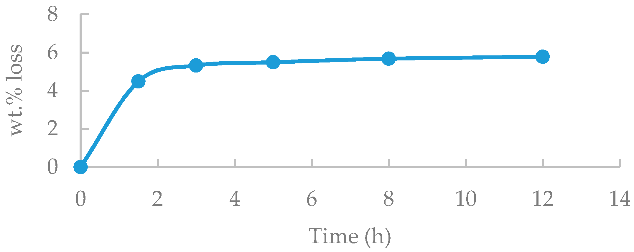
is the weight after the solvent debinding process. The following graph shows the experimental results of the weight loss ratio of the part over time in hexane at a constant temperature of 50 °C. The appropriate time for solvent debinding can be deduced from Figure 9 that the weight reduction rate during the solvent debinding increases for the first 8 h, but then converges afterwards.
Binders with low molecular weights, such as SA or PW, are weak to heat and may decompose and crack before sufficient channels to the surface are formed. Therefore, it is necessary to form a channel during the solvent debinding. 5.68 wt. % of SA and PW (total 5.75 wt. %) are removed after the solvent debinding process and the remaining SA and PW are removed completely at the thermal debinding stage as shown in 
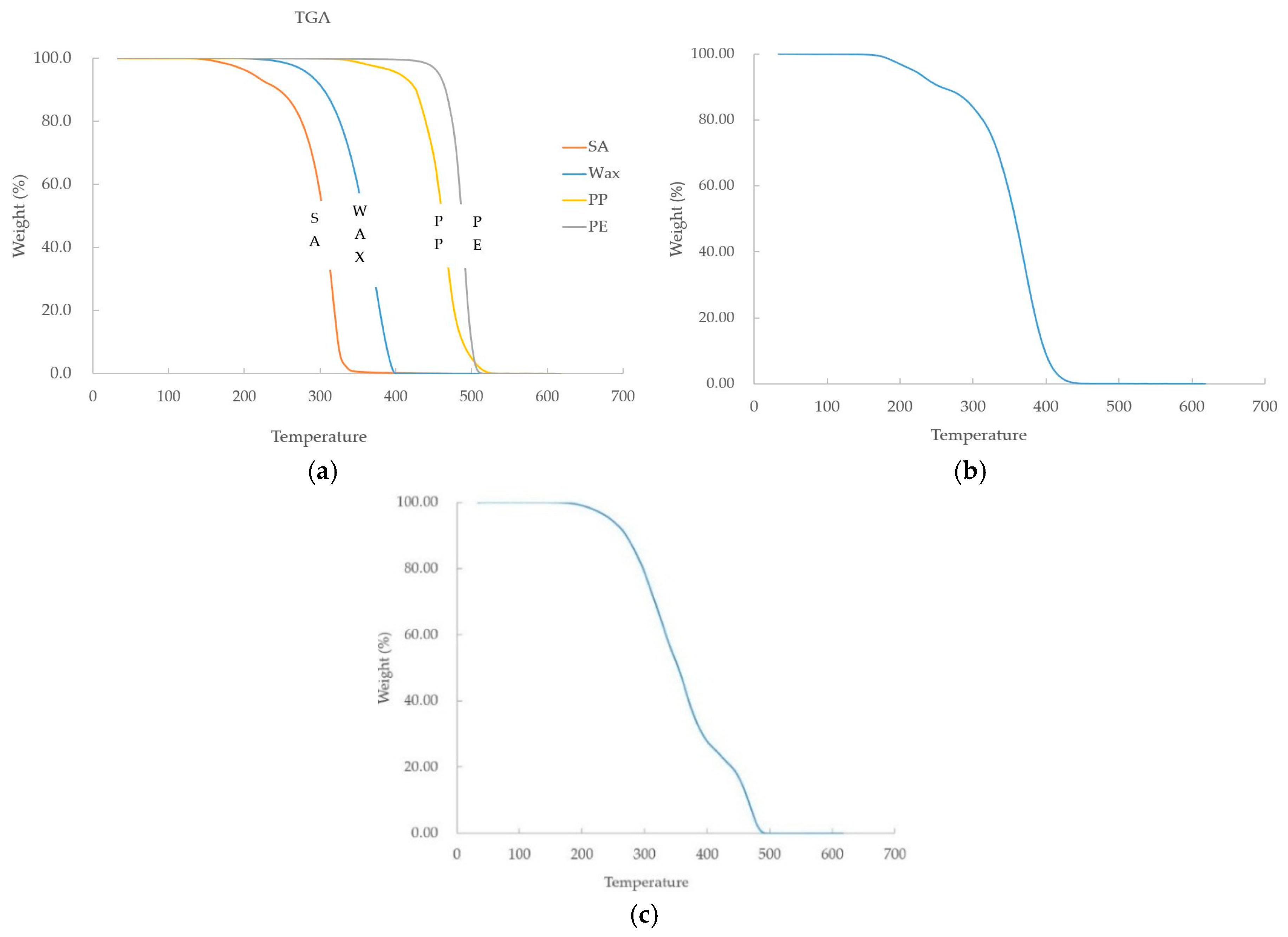
Table 8. The thermal debinding process conditions can be obtained from the thermal properties of the constituents of the binder and space holder. Therefore, mass change with time was observed using a thermogravimetric analyzer (Mettler Toledo TGA/DSC 1, Columbus, OH, USA) to obtain the decomposition temperature of the binder and PMMA. The TGA measurement was carried out at 30–600 °C at a heating rate of 10 °C/min in a hydrogen atmosphere, much like the debinding process atmosphere (Figure 10).
In this study, a binder composed of PW, SA, PP, and PE was used. The TGA results show that SA and PW start to decompose between 180 °C and 200 °C, and decompose completely between 380 °C and 400 °C. Then, decomposition of PP and PE start at 380–400 °C, where SA and PW were completely decomposed, and decomposed completely at about 500 °C. In the case of PMMA, decomposition starts at 180 °C to 200 °C, and decomposes completely at 440 °C, similar to decomposition start temperature of PW and SA. The TGA results of the feedstock show that the mass started to decrease at 180 °C to 200 °C as the result of the binder and PMMA. After that, SA, PW, and PMMA decreased rapidly at 200 °C and 400 °C, respectively.
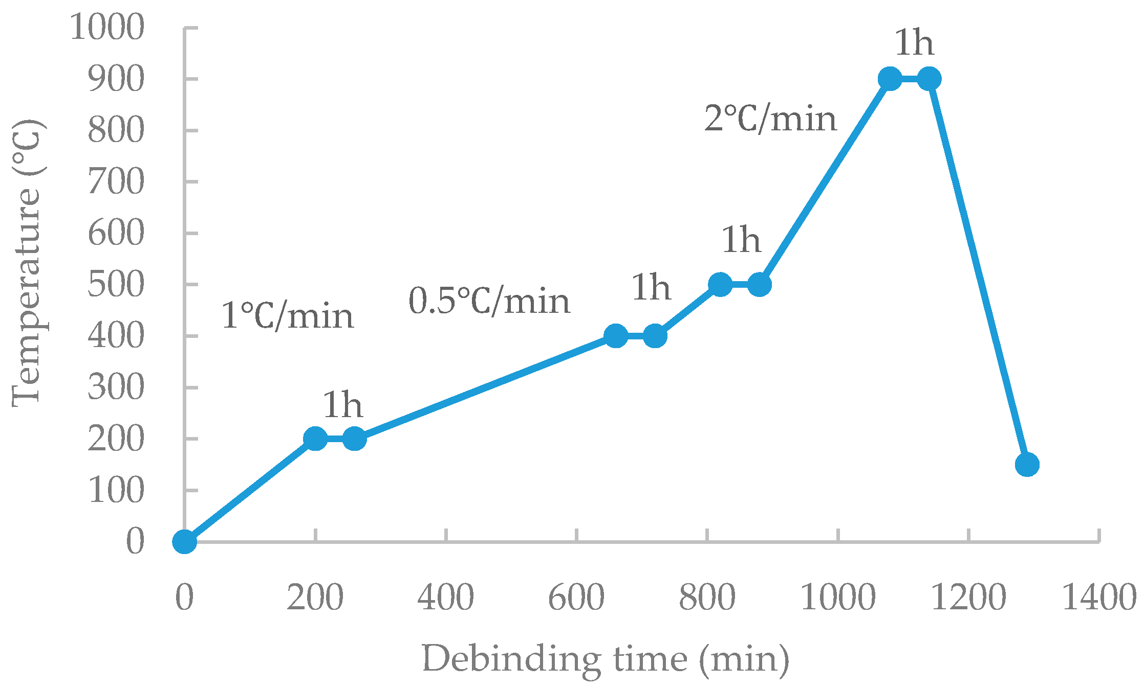
Debinding conditions were set through the decomposition temperature obtained from TGA results.
Stage 1. Decomposition of SA and PW (Up to 200 °C by 1 °C/min for channel formation and then held for 1 h).
Stage 2. Complete decomposition of SA and PW, and complete decomposition of space holder (up to 400 °C by 1 °C/min then holding for 1 h).
Stage 3. Complete decomposition of PP and PE (up to 500 ° C by 1 °C/min and holding for 1 h).
During the debinding process, it was maintained at 200 °C, 400 °C, and 500 °C for 1 h so that sufficient channels for the binder’s flows can be formed. In the binder removal process, hydrogen gas was continuously supplied to remove the gas generated by decomposition of the binder.
Moreover, in order to prevent the formation of oxides on the surface of the green part, the debinding process was carried out in a hydrogen atmosphere. Through the derived debinding profile, at the first attempt, a crack was found in the debinded body.
Considering that at the first debinding stage, the weight loss at 250–400 °C originated by not only SA and PW, but also the space holder. The mixture is composed of 20 vol % of the space holder, so more time is needed than a conventional debinding. The heating rate in the range of 200–400 °C was changed from 1 °C/min to 0.5 °C/min so the space holder could be decomposed with a sufficient time. After this, the remaining binder was removed to prevent breakage in the brown part by heating up to 900 °C for pre-sintering. Finally, a brown part without cracks could be produced. The optimized debinding and pre-sintering processes are shown in Figure 11.
The mass change during solvent debinding and thermal debinding was calculated using the density and fraction of powder, binder, and the space holder by using the following equations [1]:
ρ g = ρ p V f , p + ρ b V f , b + ρ s V f , s , V f , p + V f , b + V f , s = 1
where, ρ g is the density of the green part and ρ p , ρ b , ρ s is the density of the powder, binder, and the space holder. V f , p , V f , b , V f , s is the volume fraction of powder, binder, and space holder. The sum of the volume fraction of powder, binder and space holder in the green part is constant.
In this study, the volume fraction of binder is constant at 0.4, and the value of ρ p , ρ b , ρ s are 7.95 g / cm 3 , 0.9058 g / cm 3 , and 1.19 g / cm 3 . Using these values, the mass of the green part, W g , and the volume of the green part, V g , can be calculated. Then, the mass of binder, W b , and space holder, W s , can be calculated by the following equations and the values are listed in Table 8:
W g = V g ρ g W b = V b ρ b = V f , b V g ρ b W s = V s ρ s = V f , s V g ρ s
After the solvent debinding process, the weight of the green part was reduced by 5.68 wt %; mainly, the reduced weight was the PW and SA. Since the total wt. % of PW and SA is 5.75 wt. %, the remaining PW and SA will be further removed in the following thermal debinding process. After the thermal debinding process, the final brown part weighs 16.14 g so it can be assured that the remained binders are completely removed. The sintering process was performed under the following conditions as listed in 
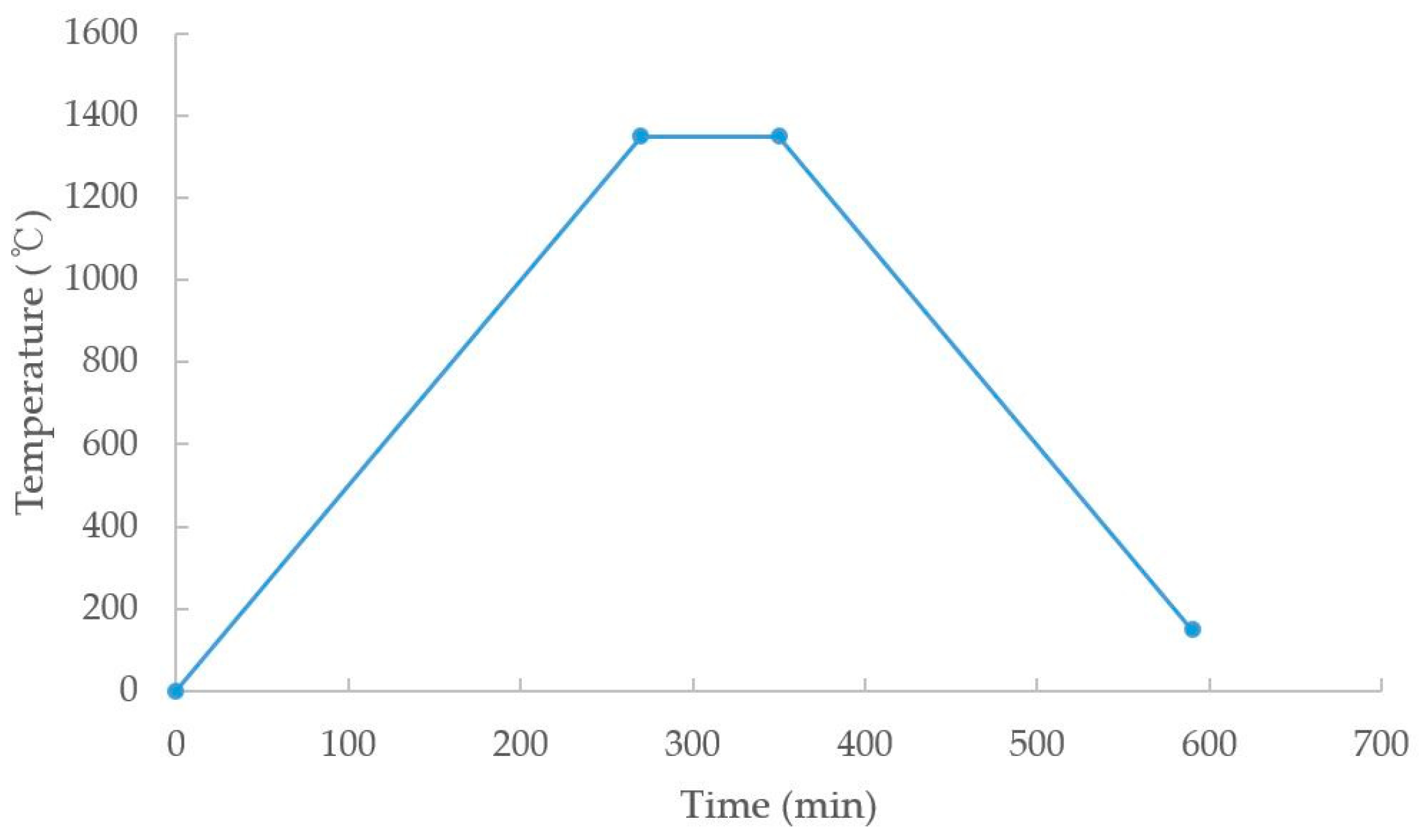
Table 9. Since the binder and space holder were removed during the debinding process, the sintering process was carried out in the same way as the conventional SUS 316L sintering process.
In general, the residual binder can be removed by maintaining the temperature around 450 °C to 500 °C, but since the binder was removed through pre-sintering during the debinding process in this study, it was omitted (Figure 12).
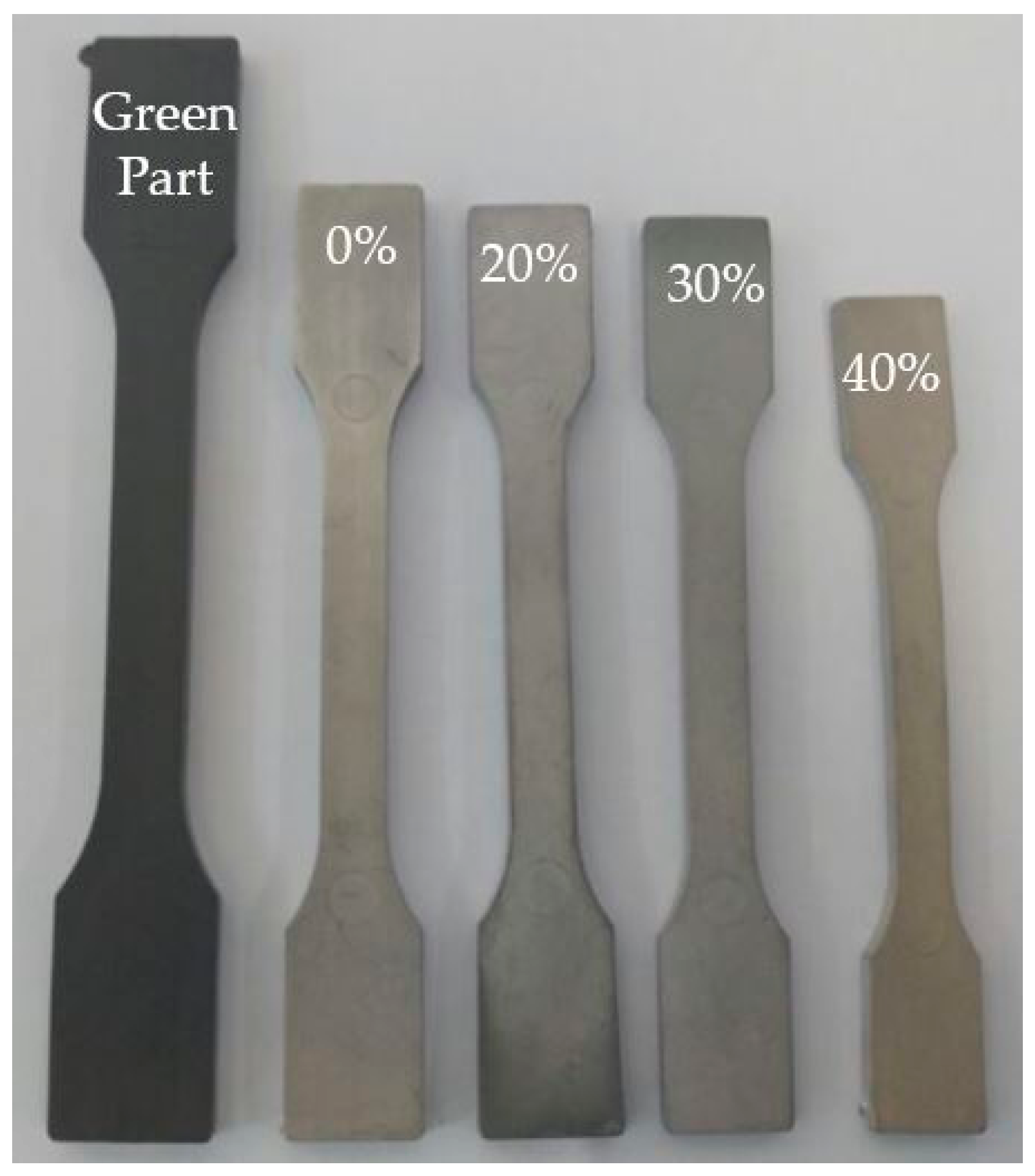
The sintering process was performed in a hydrogen atmosphere to prevent the formation of oxides due to air, and the sintering was completed by maintaining the temperature at 1350 °C for 80 min. As a result, the tensile specimen without deformation was obtained.

5. Evaluation of the Tensile Specimens

Tensile specimens with an inner porous structure were fabricated by a metal injection molding process with the space holder technique. Optimal microscope (OM) equipment was used to observe the cross-sectional area of the specimens. OM observation confirmed the presence of spherical pores in the cross-section as shown in Figure 13.
Tensile specimens with the space holder volume fraction from 0% to 40% were prepared by the method described above and the sintered parts are shown in Figure 14. Three tensile specimens were prepared from each volume fraction and the average values were used for their evaluations.
The porosity of the sintered parts is calculated by using the following porosity calculation equation. V t is the value for the apparent volume of the specimen and V s is the volume for the powder in the specimen, SUS 316L. The volume, V t was determined by Archimedes method and by micro CT scan (Nikon XT H 320, Tokyo, Japan). As the volume of the space holder increases, the weight of the sintered product becomes lighter, and the shrinkage ratio and the porosity increase.
Porosity = V t V s V t × 100
As shown in Figure 14, the leftmost part is the injection molded green part, and the volume fraction of the space holder increases toward the right. At 0, 20, and 30 vol %, it shrinks linearly, but at 40 vol % shrinkage increases sharply. As shown in Figure 15a, the shrinkage rates of sintered parts with 0, 20, and 30 vol % space holders are 14%, 16.3%, and 17.8%, respectively. Additionally, as shown in Figure 15b, the porosity of sintered parts with 0, 20, and 30 vol % space holders are 14%, 34.6%, and 47%, respectively. However, in the case of the sintered part containing 40 vol % of the space holder, it was confirmed that the shrinkage was significantly increased to 24.61%, but the porosity increasing rate decreased as listed in Table 10. Without the space holder, the shrinkage rate of the sintered part is 14%, which means additional shrinkage was from the shrinkage of the porous structure. As more space holder was added, the shrinkage of the porous structure became significant because there was greater volume from the presence of space holder and less metal powder to support the structure [1]. To retain its shape of the sintered part, vol % of the space holder above 40 vol % require special caution. The porosity measurement by micro CT scan showed the same tendency, and the volume measurement by micro CT scan is more reliable because of the characteristic of the Archimedes method that bubbles in pores cannot be sufficiently removed (Figure 16).
The specimens were evaluated for tensile strength according to MPIF standard 10. A holding force of 900 psi with 2 mm/min speed was used for the measurement (MTS Landmark, Eden Prairie, MN, USA). The strength of four different volume fractions’ specimens was measured. The tensile strength of the specimen tends to decrease as the PMMA fraction increases as shown in Figure 17.

6. Conclusions

The purpose of this study was to investigate (1) how the rheological properties of PMMA space holders vary according to the size and volume fraction of PMMA; (2) how to completely remove space holders during debinding while retaining its porous characteristics; and (3) the relationship between PMMA space holder volume fraction with shrinkage, porosity, and mechanical properties of the final sintered products. In this study, we investigated the feedstock’s rheological characteristics by capillary rheometry. Slip phenomena of the feedstock was quantified as a function of PMMA space holder size and volume fractions. To find out the critical solid loading, torque rheometer was used. The thermal properties of the feedstock were obtained using a thermogravimetric analyzer (TGA) to obtain the appropriate debinding process conditions. The tensile specimens were prepared using a feedstock having fraction of different space holders. The shrinkage, porosity, and tensile strength of the sintered parts were compared according to the volume fractions of space holder. The results can be summarized as,
● Effect of the PMMA space holder’s size and volume fraction
It was observed that the viscosity of the feedstock decreases as the size of the space holder increases, and the volume fraction of the space holder also exhibits the same tendency. The results matches with rheological characteristics of a highly-filled suspension.
● Wall slip phenomenon
The flow of powder-space holder-binder mixtures was strongly affected by slip at the wall. The slip velocity increased with size of the diameter of PMMA space holder and volume fractions. The slip velocity of the feedstock was quantified as a power law of wall shear stress.
● Debinding process optimization
The appropriate solvent debinding process time was determined through the mass reduction rate according to the time of the green part immersing in the hexane solution. Solvent debinding was performed at 50 °C for 8 h and it showed that most SA and PW were removed. After that the residual binder and space holder could be removed through the thermal debinding process conditions obtained by TGA analysis. It was necessary to lower the heating rate for the thermal debinding due to the presence of the space holder.
● Evaluation of the sintered tensile specimen
Observing the cross-section of the sintered product, it was found that spherical pores are uniformly formed. Through the calculation of porosity using Archimedes’ law and micro CT scan analysis, the porosity and shrinkage rate were measured. When 40 vol % of the space holder was added, the shrinkage was 24.61% which was significantly higher than 17.81% shrinkage of the sintered part containing 30 vol % or less of the space holder. As a result of the tensile test, it was found that the strength decreased from 471 MPa (0 vol %) to 218 MPa (20 vol %), 125 MPa (30 vol %), and 94 MPa (40 vol %) as the amount of space holder increased.

Acknowledgments

This work was supported by a two-year research grant of Pusan National University.

Author Contributions

Sang June Park and Dongyeong Kim designed and performed the experiments, Dungguo Lin and Seong Jin Park contributed in TGA analysis for debinding. Seokyoung Ahn wrote the paper.

Conflicts of Interest

The authors declare no conflict of interest.

References

  1. Manonukul, A.; Mueya, N.; Leaux, F.; Amaranan, S. Effects of replacing metal powder space holder on metal foam produced by metal injection molding. J. Mater. Proc. Technol. 2010, 210, 529–535. [Google Scholar] [CrossRef]
  2. Heaney, D.F.; Gurosik, J.D.; Binet, C. Isotropic forming of porous structures via metal injection molding. J. Mater. Sci. 2005, 40, 973–981. [Google Scholar] [CrossRef]
  3. German, R.M. Powder Injection Molding; Cambridge University Press: Cambridge, UK, 1990. [Google Scholar]
  4. Nishiyabu, K.; Matsuzaki, S.; Ishida, M.; Tanaka, S.; Nagai, H. Development of porous aluminum by metal injection moulding. Mater. Forum 2004, 28, 376–382. [Google Scholar]
  5. Zhang, E.; Wang, B. On the compressive behaviour of sintered porous coppers with low to medium porosities. Part I. Experimental study. Int. J. Mech. Sci. 2005, 47, 744–756. [Google Scholar] [CrossRef]
  6. Nishiyabu, K.; Matsuzaki, S.; Tanaka, S. Net-shape manufacturing of micro porous metal components by powder injection molding. Mater. Sci. Forum 2007, 534–536, 981–984. [Google Scholar] [CrossRef]
  7. Dunand, D.C. Processing of titanium foams. Adv. Eng. Mater. 2004, 6, 369–376. [Google Scholar] [CrossRef]
  8. Köhl, M.; Habijan, T.; Bram, M.; Buchkremer, H.P.; Stöver, D.; Köller, M. Powder metallurgical near-net-shape fabrication of porous NiTi shape memory alloys for use as long-term implants by the combination of the metal injection molding process with space-holder technique. Adv. Eng. Mater. 2009, 11, 959–968. [Google Scholar] [CrossRef]
  9. Gülsoy, H.Ö.; German, R.M. Production of micro-porous austenitic stainless steel by powder injection molding. Scr. Mater. 2008, 58, 295–298. [Google Scholar] [CrossRef]
  10. Nishiyabu, K. Powder space holder metal injection molding (PHS-MIM) of micro-porous metals. In Handbook of Metal Injection Molding; Woodhead Publishing Limited: Cambridge, UK, 2012. [Google Scholar]
  11. Park, S.J.; Wu, Y.; Heaney, D.F.; Zou, X.; Gai, G.; German, R.M. Rheological and thermal debinding behaviors in titanium powder injection molding. Miner. Met. Mater. Soc. ASM Int. 2008, 40, 215–222. [Google Scholar] [CrossRef]
  12. Bigg, D.M.; Barry, R.G. Progress in 56th Society of Plastic Engineers–Annual Technical Conference; Carlstedt, U., Stanaszek, M.J., Eds.; CRC Press: Brookfield, CT, USA, 1998; pp. 997–1000. [Google Scholar]
  13. Ahn, S.Y.; Kwon, T.H. Slip characterization of powder/binder mixtures and its significance in the filling process analysis of powder injection molding. Powder Technol. 1995, 85, 45–55. [Google Scholar]
  14. Soltani, F.; Yilmazer, U. Slip velocity and slip layer thickness in flow of concentrated suspensions. J. Appl. Polym. Sci. 1998, 70, 515–522. [Google Scholar] [CrossRef]
  15. Mooney, M. Explicit Formulas for Slip and Fluidity. J. Rheol. 1931, 2, 210. [Google Scholar] [CrossRef]
  16. Ibrahim, M.H.I.; Amin, A.M.; Wahab, M.S.; Asmawi, R.; Mustafa, N. Solvent debinding variables on leaching Fat, Oil and Grease (FOG) derivatives of green part stainless steel SS316L metal injection moulding. In Proceedings of the International Symposium on Technology Management and Emerging Technologies (ISTMET), Kedah, Malaysia, 25–27 August 2015; pp. 273–278. [Google Scholar]
Figure 1. Scanning electron microscope photographs of (a) SUS 316L powder; (b) polymethyl methacrylate (PMMA) space holder: 20 μm; (c) PMMA space holder: 50 μm; and (d) PMMA space holder: 80 μm.
Metals 07 00120 g001
Figure 2. Scanning electron microscope photograph of powder, binder, and polymethyl methacrylate (PMMA) space holder (50 μm) mixture.
Metals 07 00120 g002
Figure 3. (a) Torque vs. time for finding critical solid loading, and (b) torque vs. solid loading using a torque rheometer.
Metals 07 00120 g003
Figure 4. (a) Viscosity vs. shear rate results of F1, F2, F3, F4; and (b) viscosity vs. shear rate results of F1, F3, F5, F6.
Metals 07 00120 g004
Figure 5. Velocity profiles of a suspension fluid at the wall: (a) no-slip; and (b) slip velocity (Vs).
Metals 07 00120 g005
Figure 6. Apparent shear rate vs. 1/D for F6 which are SUS 316L:space holder:binder = 20:40:40 vol %, polymethyl methacrylate (PMMA) particle size = 50 μm showing wall slip by using Mooney’s method.
Metals 07 00120 g006
Figure 7. Slip velocity versus shear stress for different polymethyl methacrylate (PMMA) volume fractions (a) and sizes (b).
Metals 07 00120 g007
Figure 8. Scanning Electron Microscope (SEM) photograph of tensile specimen ‘green’ part.
Metals 07 00120 g008
Figure 9. Weight loss changes with time for the solvent debinding.
Metals 07 00120 g009
Figure 10. TGA results of (a) pure binder; (b) space holder; and (c) feedstock.
Metals 07 00120 g010
Figure 11. An optimized thermal debinding profile with pre-sintering process.
Metals 07 00120 g011
Figure 12. An optimized sintering profile for this study.
Metals 07 00120 g012
Figure 13. Optical photograph (a) and Scanning Electron Microscope (SEM) photograph (b) showing the cross-section of the sintered part with 30 vol % of polymethyl methacrylate (PMMA).
Metals 07 00120 g013
Figure 14. Sintered part and green part for different polymethyl methacrylate (PMMA) volumes.
Metals 07 00120 g014
Figure 15. Comparison of sintered part with varied contents of polymethyl methacrylate (PMMA) shrinkage and porosity (a) shrinkage and (b) porosity effect of PMMA size.
Metals 07 00120 g015aMetals 07 00120 g015b
Figure 16. Micro CT scan of the tensile specimens and the porosity results for different polymethyl methacrylate (PMMA) space holder volume fractions.
Metals 07 00120 g016
Figure 17. Tensile strength of sintered part with varied contents of polymethyl methacrylate (PMMA) space holder.
Metals 07 00120 g017
Table 1. Particle size and density of metal powder (SUS 316L) used.
SUS 316LParticle Size (D50)Density (g/cm3)
8.10 μm7.95
Table 2. Binder compositions and related properties.
PropertyPWPPPESA
Density (g/cm3)0.920.920.930.95
Melting temperature (°C)517812053
Decomposition temperature (°C)242~280464~481464~471246~275
Table 3. Powder space holder (PMMA) characteristics used for feedstock.
PMMAParticle Size (D50)Density (g/cm3)Melting Temperature (°C)
P120 μm1.19165
P250 μm1.19165
P380 μm1.19165
Table 4. Feedstocks with various polymethyl methacrylate (PMMA) space holder sizes (20, 50, 80 μm) and their volume percentages.
Feedstock NumberingSUS 316L (vol %)PMMA (vol %)Binder System (vol %)
F160040
F24020 (P1, 20 μm)40
F34020 (P2, 50 μm)40
F44020 (P3, 80 μm)40
Table 5. Feedstocks with various PMMA space holder vol % with the fixed size (P2, 50 μm) and their volume percentages.
Feedstock NumberingSUS 316L (vol %)PMMA (vol %)Binder System (vol %)
F160040
F3402040
F5303040
F6204040
Table 6. Slip velocity as a function of a power law for each feedstock.
Feedstock (Powder:Space Holder:Binder (vol %), Space Holder Size)Slip Velocity (mm/s)
F1 (60:40)Vs = 5 × 10⁻⁵ τ w 1.2263
F2 (40:20:40, 20 μm)Vs = 0.0064 τ w 0.8427
F3 (40:20:40, 50 μm)Vs = 0.0151 τ w 0.7692
F4 (40:20:40, 80 μm)Vs = 0.0068 τ w 0.8592
F5 (30:30:40, 50 μm)Vs = 0.0178 τ w 0.7672
F6 (20:40:40, 50 μm)Vs = 0.0191 τ w 0.85
Table 7. Injection molding parameters used for experimental study.
ParameterValue
Fill time1.4 s
Injection temperature150 °C
Packing time4.0 s
Mold temperature40 °C
Cooling time10.0 s
Cycle time51.0 s
Table 8. Weight loss analysis of the tensile specimen during the debinding process.
Green Part CompositionsAfter Solvent DebindingAfter Thermal Debinding
Feedstock100 wt. % (19.19 g)18.10 g16.14 g
SUS 316L84.12 wt. % (16.14 g)16.14 g16.14 g
PW5.51 wt. %−1.09 g (−5.68 wt. %)−1.96 g (−10.20 wt. %)
SA0.24 wt. %
PP2.40 wt. %
PE1.44 wt. %
PMMA6.29 wt. %
Table 9. A sintering cycle used for the study.
Time (min)Temperature (°C)Heating Rate
0205 °C/min.
2701350
3501350holding time 80 min.
590150cooling
Table 10. Comparison of the weight, shrinkage, and porosity of sintered parts produced at different PMMA volume ratios.
Weight (g)Linear Shrinkage (%)Porosity (%) by Archimedes’Porosity (%) by Micro CT ScanDensity (g/cm3)
PIM–SUS 316L (6:4)23.851414.289.537.21
PIM–PSH (4:2:4)16.1416.3234.5927.785.74
PIM–PSH (3:3:4)12.6417.8147.0040.994.69
PIM–PSH (2:4:4)7.8824.6152.8047.814.14

