Article

TiO2 Nanotubes on Ti Dental Implant. Part 1: Formation and Aging in Hank’s Solution

Deptartment of Chemical Engineering, Materials and Industrial Production, University of Napoli Federico II, Piazzale Tecchio 80, 80125 Napoli, Italy
*
Author to whom correspondence should be addressed.
Metals 2017, 7(5), 167; https://doi.org/10.3390/met7050167
Submission received: 11 April 2017 / Revised: 4 May 2017 / Accepted: 8 May 2017 / Published: 11 May 2017

Abstract

:
Self-organized TiO2 nanotube layer has been formed on titanium screws with complex geometry, which are used as dental implants. TiO2 nanotubes film was grown by potentiostatic anodizing in H3PO4 and HF aqueous solution. During anodizing, the titanium screws were mounted on a rotating apparatus to produce a uniform structure both on the peaks and on the valleys of the threads. X-ray diffraction (XRD), Scanning electron microscopy (SEM), Energy dispersive X-ray (EDX) and electrochemical characterization were used to evaluate the layer, chemical composition and electrochemical properties of the samples. Aging in Hank’s solution of both untreated and nanotubes covered screw, showed that: (i) samples are covered by an amorphous oxide layer, (ii) the nanotubes increases the corrosion resistance of the implant, and (iii) the presence of the nanotubes catalyses the formation of chemical compounds containing Ca and P.

1. Introduction

Titania (TiO2) nanostructures, such as nanowires, nanofibers, nanorods, nanoribbons, nanoplates and nanotubes, are widely studied materials due to their unique properties in optics, electronics, photochemistry and biology finding applications in photovoltaic cells, photocatalysis, and sensors [1,2,3,4,5]. Additionally, materials with well-ordered nanostructure are of considerable interest for application in molecular filtration, drug delivery and tissue engineering [6,7,8]. The broad application of TiO2 nanostructures is mainly due to the attractive nano-scale architecture offering large surface area and a high structural order. Titanium is used in orthopedic and dental applications for its biocompatibility and optimal mechanical properties in load-bearing application [9,10]. However, the insufficient new bone formation is observed due to necrosis of hard and soft tissues that result in the implant loosening and subsequent failure [11,12]. The titanium implant surface shape and chemical composition have also been studied to enhance osseointegration, decrease necrosis and prevent inflammation [13,14,15,16,17,18,19,20,21]. Titania nanotubes, formed by anodic oxidation, are a candidate method for the modification of the surface of titanium implants to enhance bone formation function. It is well known that nanotubes can be produced by anodizing flat titanium specimens [22,23,24,25], some studies [5,19] report nanotubes growth on the wire, meshes or curved surfaces. Very few [26,27] works deal with the use of complex geometry samples. A variety of electrolytes and conditions have been used to prepare TiO2 nanotubes [28,29]. Results obtained in these investigations suggest that the nanotubes morphology and cells spreading are controlled by the anodizing potential, the electrolyte composition, and its physical properties, primarily conductivity, viscosity and temperature, as well as by the duration of the anodizing process.
The aim of the present work was to form a uniform distribution of TiO2 nanotubes, by using a relatively simple experimental set-up, on specimens with complex geometry, such as a titanium screw, commonly used as a dental implant and characterize its chemical and physical properties in term of structure, shape and length of nanotubes. Also, TiO2 nanotubes were aged in Hank’s solution for 15 days to: (i) evaluate the electrochemical properties when compared to the untreated sample, (ii) increase implant biocompatibility by forming calcium-phosphate compounds on the surface without any prior thermal treatment on the implant.

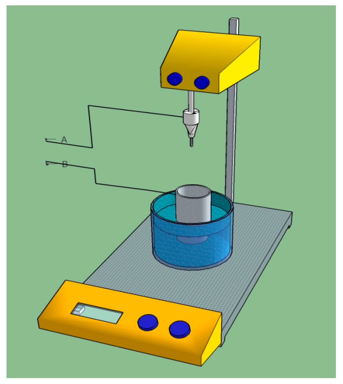
2. Materials and Methods

The specimens used in this work were dental implant screws provided by Deltal Medics (Milano, Italy), 3 mm in diameter and 8 mm in length (Figure 1). The screws were pickled in a water solution containing hydrochloric acid (10 wt %) and nitric acid (10 wt %) for 20 min, to stabilize the natural oxide layer existing on the implants. The implants were made in Ti CP2, whose composition is reported in Table 1. The name assigned to the samples were: (i) AS to indicate the screw submitted to acid pickling and (ii) NT the screw on which nanotubes were grown.
TiO2 nanotubes, formed on the implant, were obtained by potentiostatic anodizing in an aqueous solution of H3PO4 (10 wt %) and HF (0.5 wt %), by applying a potential of 25 V for 150 min at 25 °C. During the anodizing, the titanium screw was the anode and a platinum foil the cathode of the electrochemical cell. To obtain a uniform nanotubes layer, the screw was mounted on a rotating device; the rotation speed was set at 10 rpm (please for further details see the Results and discussion section). The experimental set-up adopted in this investigation is schematically represented in the Figure 2. A laboratory mixer was used to sustain and rotate the screw, and a conductive support, connected to the rod of the stirrer, allowed the electrical connection between the specimen and the positive pole of the power supply Gen 600-5.5 (TDK-Lambda, Milano, Italy). In order to ensure reproducibility and accuracy three samples have been employed, renovating the test solution for each sample.
After anodizing, the specimens were rinsed with deionized water and dried in air. The surface morphology of the fabricated TiO2 nanotube films was characterized by scanning electron microscopy (SEM) (Supra 40 VP FESEM, Zeiss, Milano, Italy). Furthermore, 2D profiles were acquired by using software WSxM (WSxM v5.0 Develop 8.5, WSxM solutions, Madrid, Spain, 2016). Also, X-ray diffraction (XRD) spectra were obtained by using Panalytical X’Pert system in Bragg-Brentano and grazing incidence X-ray diffraction (GIXRD) geometry configuration. The atomic composition of surface layers of the samples was detected by using an energy dispersive X-ray (EDX) analysis at 15 keV, keeping electron beam stationary to obtain the spectra. In this configuration, the spot size can be estimated in 0.1 µm with a volume excited of 1 µm3. Finally, electrochemical tests were carried out by using a standard three electrodes configuration, including a saturated calomel reference electrode (SCE), a platinum electrode as counter-electrode and the titanium sample as working electrode connected to a potentiostat/galvanostat, 1286 Solartron (Photo Analytical Srl, Milano, Italy). The area of specimens exposed to the standard Hank’s aqueous solution (Sigma-Aldrich, Milano, Italy, composition reported in Table 2), was estimated in about 3 cm2. Measurements were carried out starting 10 mV below the open circuit potential (OCP) after immersion in the salt solution up to an immersion time of 15 days (360 h). To maintain a constant test environment, the solution was renewed every two days.

3. Results and Discussion

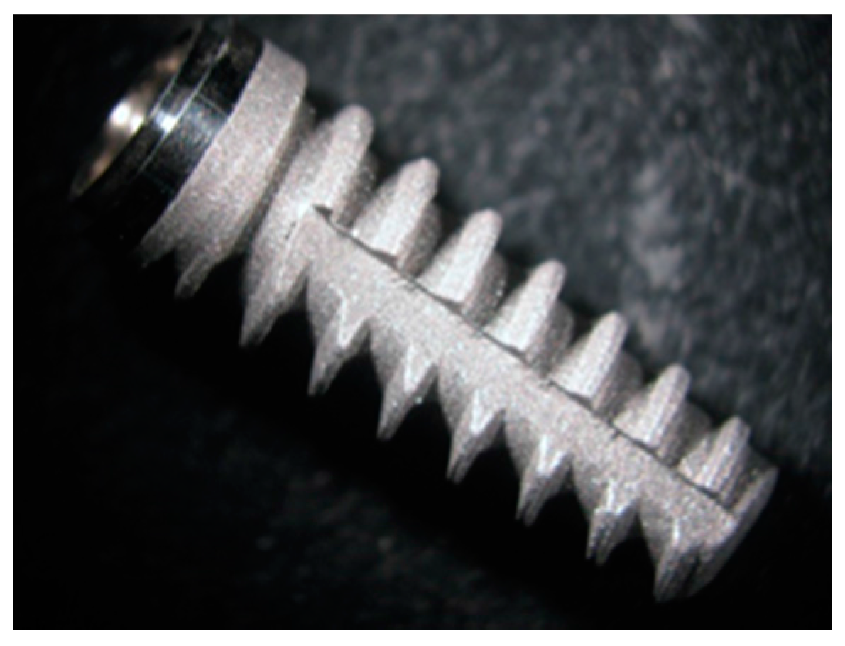
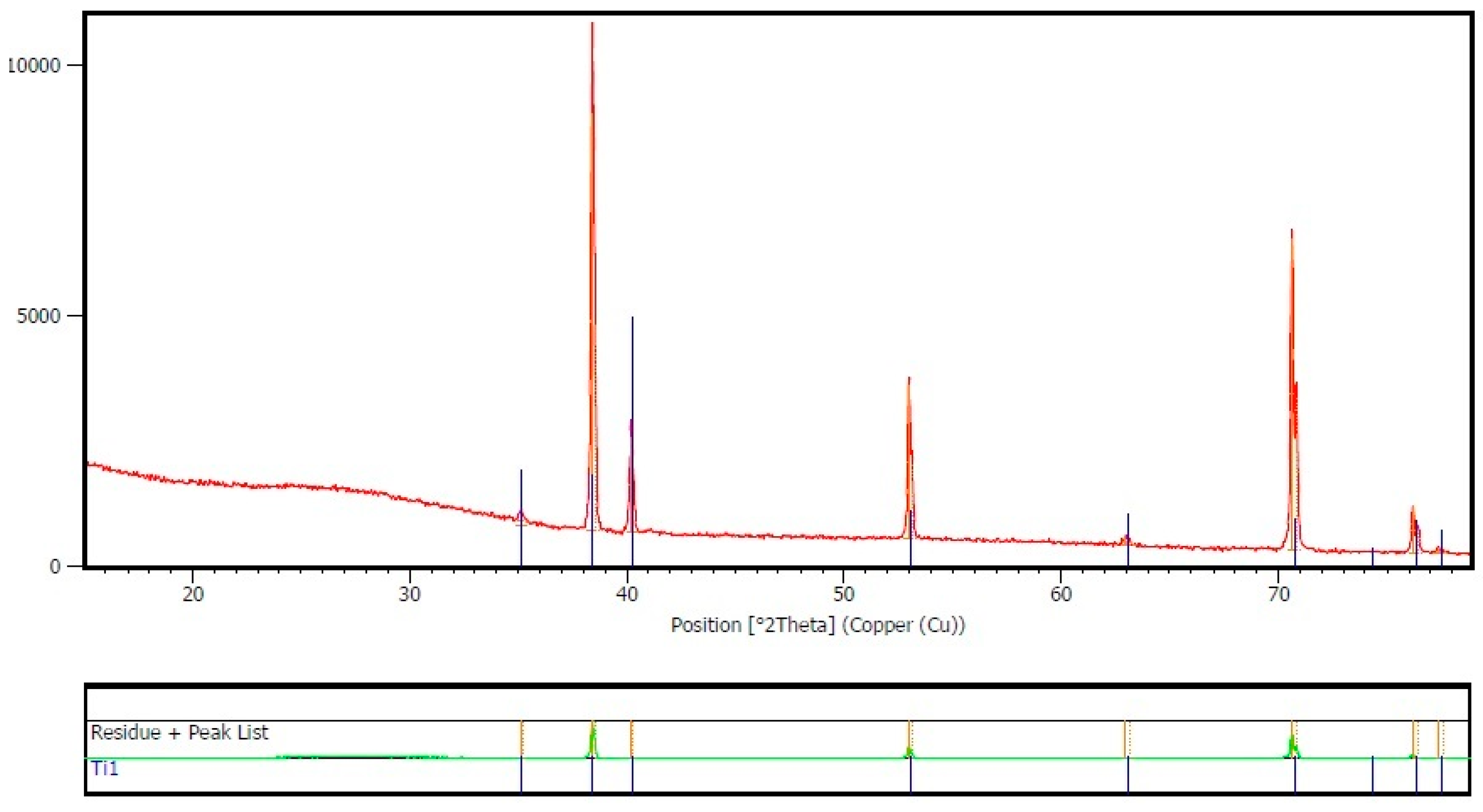
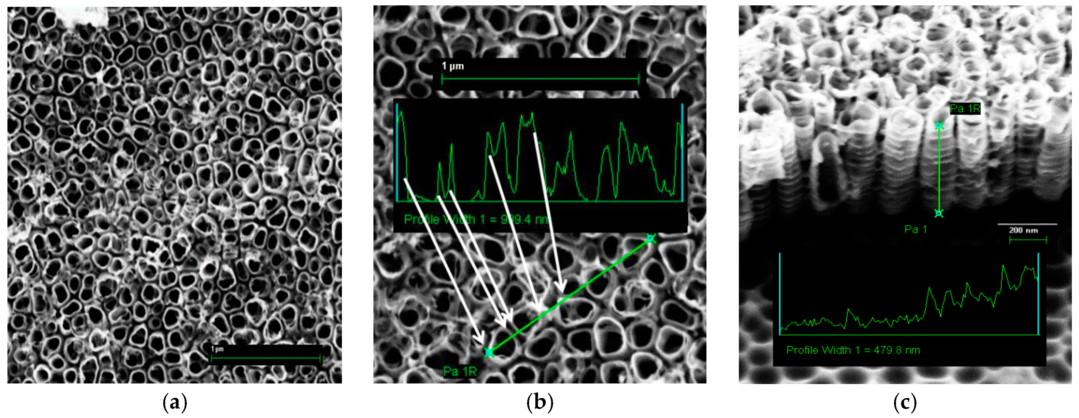
3.1. Nanotubes Formation and Structure

It is well known that the formation of nanotubes on a flat surface is dependent on various process parameters (temperature and solution composition, applied voltage, anodizing duration) [28,29]. However, for complex geometries, such as those of dental implants, an additional parameter plays a significant role in nanotubes formation. In fact, previous results showed that only selected rotation speeds of the screw, determine the growth of a uniform distribution of nanotubes on the whole screw surface [27]. A detailed check of the anodized implant surface, by using SEM images, revealed that the screw was completely coated by an anodic oxide: the flat areas of the screw were covered by an ordinated and uniform array of nanotubes, while the edges between two flat areas, showed a less organized structure. Namely, it was so far observed that in the case of motionless (0 rpm) or low rotation speed (1 rpm) of the sample, the nanotubes growth occurs preferentially on the peak of the screw turns, while, for high rotational speed (60 rpm), the formation of nanotubes is suppressed. This result was so far explained on the basis of the following arguments. At zero or low speed of rotation (1 rpm) the flux lines of the electric field are intense at the peaks of the thread, promoting the formation of “local” nanotubes, while the valleys of the thread, are affected by a reduced electric field, due to shielding effect of screw wall, that is not sufficient to sustain nanotubes formation. Both the reduced electric field and the slow rotation speed could, also, reduce the fluoride ions uptake on the Ti surface inhibiting nanotubes formation. On the other hand, in the case of high rotation speed (60 rpm), the fluid-dynamic regime is such as to ensure very high uptake of fluoride ions onto the surface to inhibit nanotubes growth. However, a uniform growth of nanotubes, on both peaks and valleys, were obtained for a rotational speed of 10 rpm that was the speed adopted in this investigation.
A typical nanotubes structure obtained according to the experimental procedure outlined above is shown in Figure 3a. As can be seen from this figure, nanotubes were uniformly distributed on the sample surface while determining the formation of a gap between them. It is worth to mention that these gaps can be used as an additional reservoir for controlled drug delivery of drugs, or other chemicals, impregnated in/on the structured surface [6]. The nanotubes diameters shown in Figure 3a were in the range of 130–170 nm and about 480 nm in length. Furthermore, nanotubes assumed the typical “bamboo type” [30] shape as confirmed by the profile reported in Figure 3c, in which the contour of a single nanotube is reported. An interesting characterization of the topography of formed nanotubes (reported in Figure 3b) allows estimating the nanotubes wall thickness (about 2 nm) and the gap between two nanotubes (equal to 4 nm) showing that large areas of the surface are available to be impregnated by using chemicals and/or drugs, as mentioned above.
XRD measurements were carried out by using the conventional symmetrical Bragg-Brentano configuration on AS and NT samples for evaluating the structure of the TiO2 oxide layer on the specimens surfaces. Data obtained examining sample NT, shown in Figure 4, do not highlight any crystallographic phase of oxides, whereas, an amorphous structure was detected [31]. The AS sample showed similar signals, not reported for the sake of simplicity.
However, it must be pointed out that the conventional symmetrical Bragg-Brentano configuration (θ/2θ), should not be used for the characterization of thin oxide layers formed on metals due to the poor signals obtained from the film while receiving a strong signal from the substrate. Also, due to the substrate structure, the depth of analysis changes while performing the test. Therefore, to confirm the previously reported results a more powerful technique of X-ray diffraction at grazing incidence has been used to minimize the contribution due to the substrate. In this approach, the incidence angle is fixed at a small angle (1–3°) while the angle existing between the incident beam and the diffracted beam (2θ) is varied, moving only the detector arm. In such way, the signal coming from the substrate is reduced due to the small angle of incidence, while the incident beam penetrates, for a higher thickness the surface film, reinforcing its diffraction pattern. It has well assessed that, if the incidence angle is small as in this case, the depth of analysis is controlled by the angle of incidence and does not vary during the sweeping so that the structure of oxide even in very thin layers, can be evaluated. XRD scans obtained at 1, 1.5, 2 and 3 degrees of incidence angle (Figure 5), confirmed the absence of the anatase and/or rutile phase inside the nanotube layer.
After 15 days of aging in Hank’s solution, both samples were examined for evaluating chemical composition of eventual layers formed. EDX results, for both samples, are reported in Figure 6. As can be seen from the Figure 6a no traces of Ca or P, as well as other chemicals contained in Hank’s solution, were detected at the end of the aging on the AS sample. This finding suggests that: (i) the deposition of apatite-like compound cannot be achieved by immersion of sample in saline solution under the conditions used in this test campaign, in agreement with literature data [32,33,34,35,36,37], and (ii) the OCP trend observed for such sample cannot be attributed to the formation /dissolution of salts at the metallic solution interface.
However, quite different was the behavior of aged NT samples, as can be seen from the EDX results reported in Figure 6b. A small amount of Ca and P (about 1% atomic) were detected suggesting a partial coverage of the nanotubes by an apatite-like structured film (over other chemical species such as Mg). On the other hand, the formation mechanism of nanotubes involves the dissolution of oxide due to the acidic environment assisted by fluoride ions, which allow the subsequent nanotube growth [25]. Hence, the presence of F, detected by the EDX analysis, can be attributed to the fact that the titanium oxide nanotubes retain a small quantity of F at the bottom of pores in the formed layer.

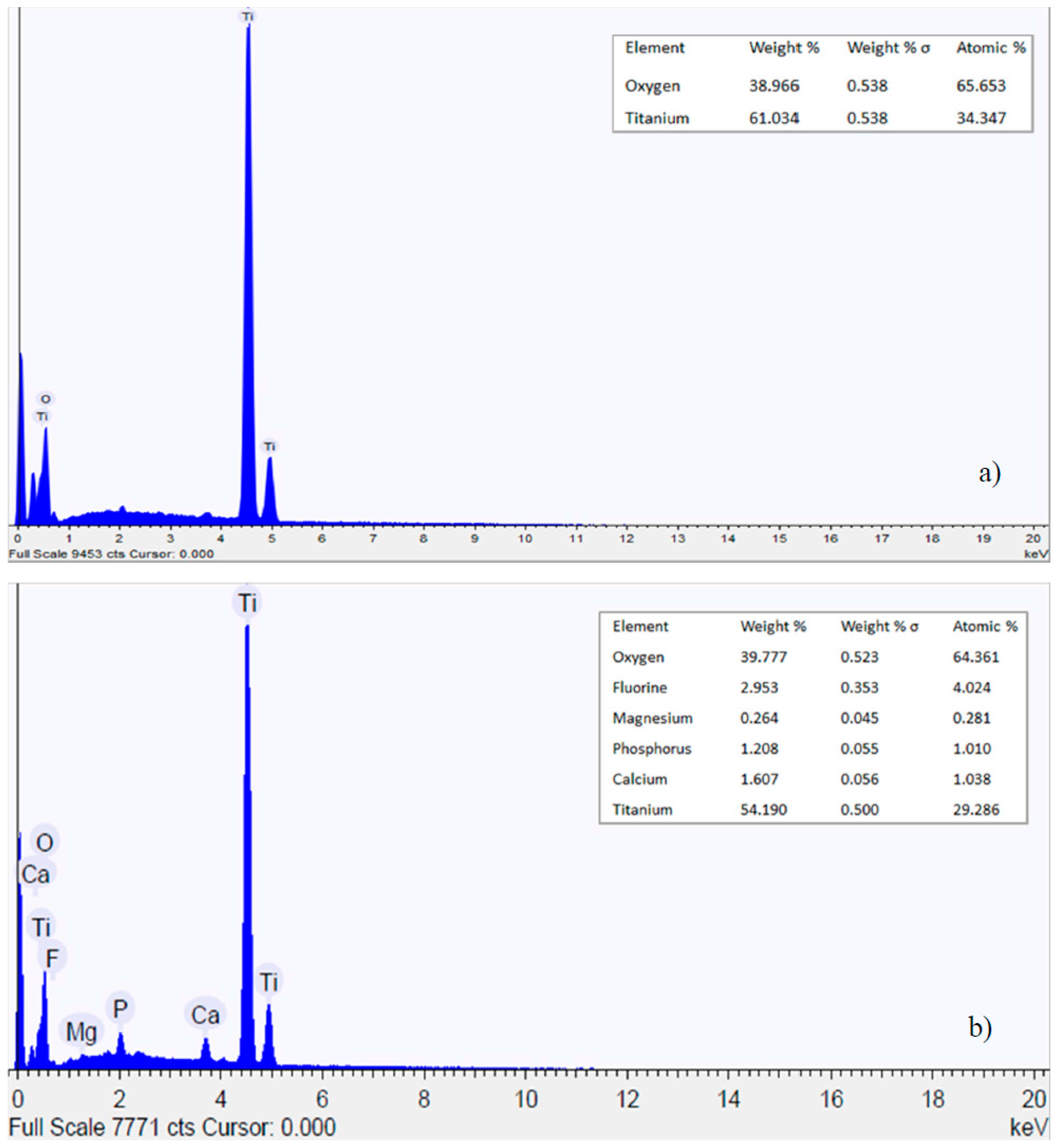
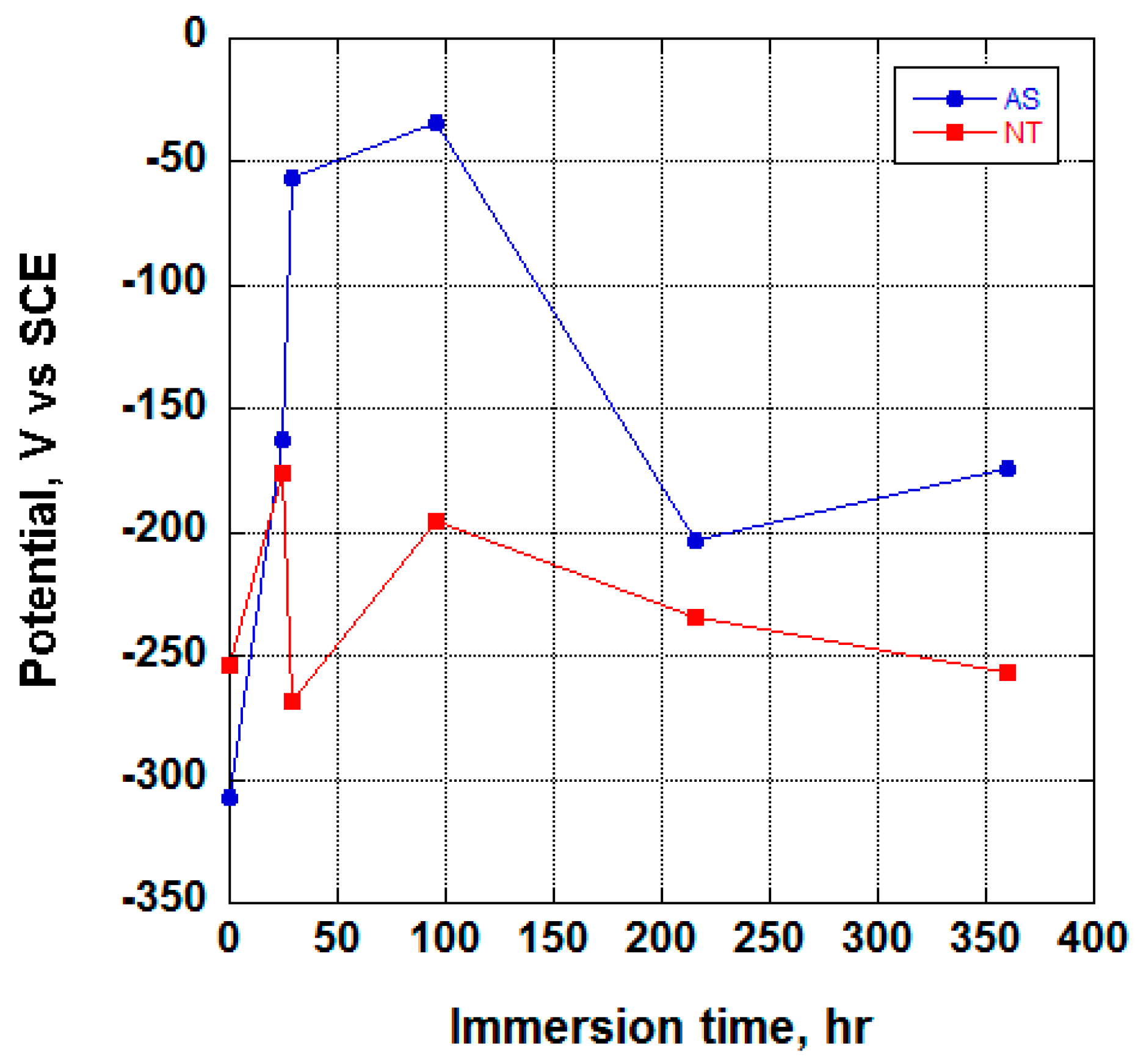
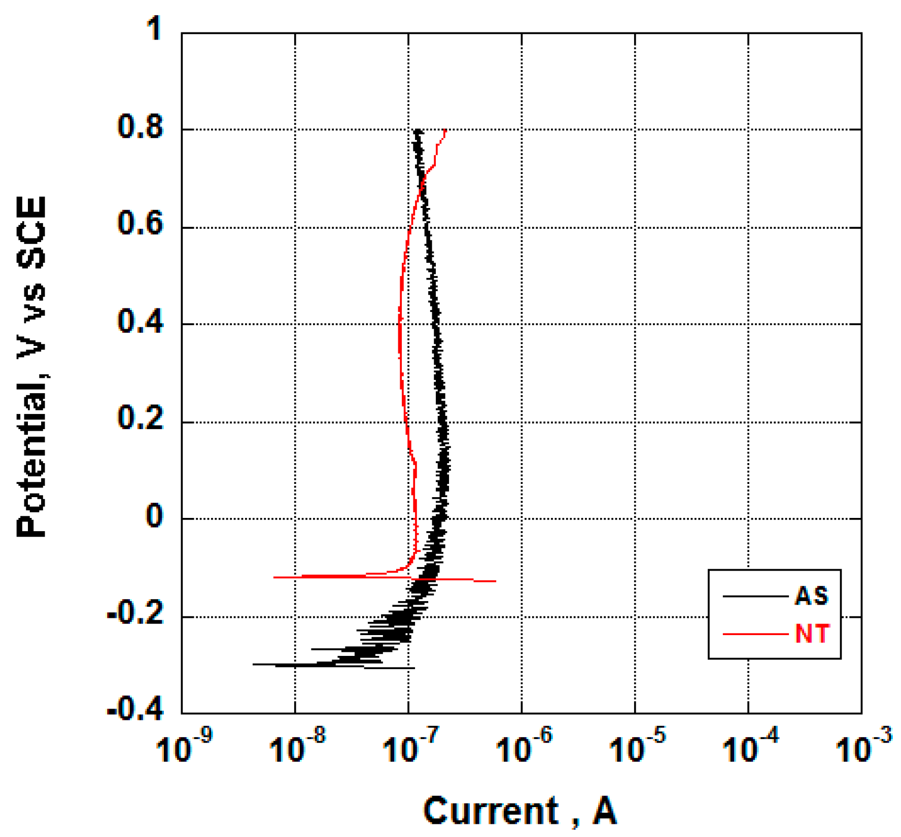
3.2. Electrochemical Behavior and Aging in Hank’s Solution

In this paper, the electrochemical behavior of both anodized and bare titanium implant was investigated in Hank’s solution, to confirm that nanotubes growth on Ti surface significantly influences the electrochemical properties of Ti samples. Also, the aging of such implant for 15 days, in the selected simulated body fluid, was also addressed to monitor the formation of chemical compounds containing Ca and P onto the sample surface. In Figure 7, the potentiodynamic polarization curves, obtained upon immersion in the test solution, of the AS and NT samples at the beginning of test campaign, are reported.
Data have shown the different behavior exhibited by NT and AS samples. As can be seen, the nanotubes sample shows a higher OCP and a lower passive current, suggesting a better corrosion behavior compared to the non-anodized sample. This evidence can be addressed to the higher thickness of its oxide layer, if compared to the AS sample, which makes available a smaller extent of anodic areas. In addition, it is well-known that the anodized sample is characterized by a much higher active surface compared to the AS sample, leading to lower current density if the ‘true’ extent of surface is considered. Since the current density is related to the durability of the metallic sample, it is expected that the anodized titanium implant will offer better corrosion resistance compared to the non-anodized sample.
In addition to the electrochemical behavior reported above, the aging of Ti samples in Hank’s solution was also addressed by monitoring the OCP as a function of the immersion time (Figure 8). It is well-known that changes in the OCP values highlight the oxide layer formation/dissolution process at the sample/solution interface. In addition, if the sample is exposed to an aqueous water solution containing dissolved salts, deposition/dissolution of chemical species contained in the solution should also be considered.
As can be seen from Figure 8, at the beginning of the test (t = 0), the anodized sample exhibited a higher value of the OCP compared to the AS sample. After 24 h, both samples showed an increase of OCP values. This result could be explained by the following arguments. At this stage, the AS sample can be considered fully covered by an air formed TiO2 layer in contact with the air-saturated Hank’s solution. While, the NT sample is covered by a TiO2 layer, grown in the anodizing solution, and nanotubes are filled with the test solution. Electrochemical data shown in Figure 8, suggested a better oxygen cathodic behavior of the latter oxide. In fact, the inner and the outer surface of nanotubes is accessible to the oxygen and thus the full “nanotubes surface” is available to the air saturated solution. Therefore, during the early stage of immersion, both the AS and the NT samples are covered by TiO2, in contact with an air saturated oxygen solution and the trend of the OCP versus the immersion time of both samples can be attributed to the grow of the TiO2 oxide in both cases.
With prolonged immersion time (29 h), however, this picture may change due to the oxygen reduction process along the pores. As mentioned above, the oxygen cathodic process onto the TiO2 covering the nanotube is faster compared to that occurring onto the air formed oxide. Thus, it is a simple matter of fact that, for further immersion time, oxygen will be limited at the bottom of the pores that become more anodic compared to the top of the pore. Thus, aging may lead to a distribution of potential inside the pores with the bottom more anodic than the top. In short, the cathodic process becomes the rate-limiting step due to the limiting diffusion of oxygen inside the pores. At this stage of immersion, therefore, the dissolution of TiO2 is not balanced by the oxide formation, thus leading to the development of more anodic sites at the bottom of the nanotubes due to the lack of oxygen. As a matter of fact, the OCP of the NT sample becomes more anodic. Due to the presence of more anodic area, the electrochemical reactions taking place at the bottom of the nanotubes may change again since the Ti4+ coming from the anodic dissolution of Ti can compete with water and negative phosphorus anions, partially filling the pores and leading to a “pseudo conversion protective layer”. At the top of the nanotubes, which is more cathodic and is in the presence of slightly basic pH, a chemical compound containing Mg, Ca and P can be formed. Both these effects lead to an increase of the OCP.
For further aging (216 h) the NT sample exhibits an OCP decrease that, following Zhang [38] is due to a two steps mechanism involving H+ produced at the interface area where corrosion occurs:
Ti + 2H2O → TiO2 + 4H+ + 4e
With the subsequent dissolution of the apatite–like coating according to the following reaction:
Ca10(PO4)6(OH)2 + 2H+ → 10Ca2+ + 6(PO4)3− + H2O
The dissolution of the apatite-like structure and “pseudo conversion” salt layer formed at the bottom of pores, together with the effect of the presence of ions like F and Cl, lead to a further decrease of the OCP.

4. Conclusions

The following conclusions are drawn from this study:
(1)
Nanotubes on titanium dental screw implant were grown by using a simple set up.
(2)
Nanotubes covering the implant possess an amorphous TiO2 structure, exhibiting better corrosion resistance as compared to the non-anodized Ti screw;
(3)
Upon aging in Hank’s solution for 15 days the anodized Ti screw shows compound containing Ca and P;
(4)
The nanotubes catalyzed the formation of compound containing Ca and P.

Acknowledgments

Authors did not received funds for covering the cost to publish in open access.

Author Contributions

Anna Carangelo performed the electrochemical experiments, Annalisa Acquesta performed the morphological and chemical measurments and elaborated all data, Tullio Monetta conceived the project and wrote the paper, Tullio Monetta and Francesco Bellucci analyzed the data.

Conflicts of Interest

The authors declare no conflict of interest.

References

  1. Bavyki, D.V.; Walsh, F.C. Titanate and Titania Nanotubes: Synthesis, Properties and Applications; Royal Society of Chemistry: London, UK, 2010. [Google Scholar]
  2. Ge, M.Z.; Cao, C.Y.; Huang, J.Y.; Li, S.H.; Zhang, S.N.; Deng, S.; Li, Q.S.; Zhang, K.Q.; Lai, Y.K. Synthesis, modification, and photo/photoelectrocatalytic degradation applications of TiO2 nanotube arrays: A review. Nano Rev. 2016, 5, 75–112. [Google Scholar] [CrossRef]
  3. Lan, Z.; Wu, W.; Zhang, S.; Que, L.; Wu, J. An efficient method to prepare high-performance dye-sensitized photoelectrodes using ordered TiO2 nanotube arrays and TiO2 quantum dot blocking layers. J. Solid State Electrochem. 2016, 20, 2643–2650. [Google Scholar] [CrossRef]
  4. Comini, E.; Galstyan, V.; Faglia, G.; Bontempi, E.; Sberveglieri, G. Highly conductive titanium oxide nanotubes chemical sensors. Microporous Mesoporous Mater. 2015, 208, 165–170. [Google Scholar] [CrossRef]
  5. Smith, Y.R.; Ray, R.S.; Carlson, K.K. Self-ordered titanium dioxide nanotube arrays: Anodic synthesis and their photo/electro-catalytic applications. Materials 2013, 6, 2892–2957. [Google Scholar] [CrossRef]
  6. De Santo, I.; Sanguigno, L.; Causa, F.; Monetta, T.; Netti, P.A. Exploring doxorubicin localization in eluting TiO2 nanotube arrays through fluorescence correlation spectroscopy analysis. Analyst 2012, 137, 5076–5081. [Google Scholar] [CrossRef] [PubMed]
  7. Tan, A.W.; Pingguan-Murphy, B.; Ahmad, R. Review of titania nanotubes: Fabrication and cellular response. Ceram. Int. 2012, 38, 4421–4435. [Google Scholar] [CrossRef]
  8. Beltrán-Partida, E.; Moreno-Ulloa, A.; Valdez-Salas, B.; Velasquillo, C.; Carrillo, M.; Escamilla, A.; Valdez, E.; Villarreal, F. Improved osteoblast and chondrocyte adhesion and viability by surface-modified Ti6Al4V alloy with anodized TiO2 nanotubes using a super-oxidative solution. Materials 2015, 8, 867–883. [Google Scholar] [CrossRef]
  9. Long, M.; Rack, H.J. Titanium alloys in total joint replacement—A materials science perspective. Biomaterials 1998, 19, 1621–1639. [Google Scholar] [CrossRef]
  10. Yao, C.; Webster, T.L. Anodization: A promising nano-modification technique of titanium implants for orthopedic applications. J. Nanosci. Nanotechnal. 2006, 6, 2682–2692. [Google Scholar] [CrossRef]
  11. Makihira, S.; Mine, Y.; Nikawa, H.; Shuto, T.; Iwata, S.; Hosokawa, R.; Kamoi, K.; Okazaki, S.; Yamaguchi, Y. Titanium ion induces necrosis and sensitivity to lipopolysaccharide in gingival epithelial-like cells. Toxicol. In Vitro 2010, 24, 1905–1910. [Google Scholar] [CrossRef] [PubMed]
  12. Vallés, G.; Gil-Garay, E.; Munuera, L.; Vilaboa, N. Modulation of the cross-talk between macrophages and osteoblasts by titanium-based particles. Biomaterials 2008, 29, 2326–2335. [Google Scholar] [CrossRef] [PubMed]
  13. Hotchkiss, K.M.; Reddy, G.B.; Hyzy, S.L.; Schwartz, Z.; Boyan, B.D.; Olivares-Navarrete, R. Titanium surface characteristics, including topography and wettability, alter macrophage activation. Acta Biomater. 2016, 31, 425–434. [Google Scholar] [CrossRef] [PubMed]
  14. Franková, J.; Pivodová, V.; Růžička, F.; Tománková, K.; Šafářová, K.; Vrbková, J.; Ulrichová, J. Comparing biocompatibility of gingival fibroblasts and bacterial strains on a different modified titanium discs. J. Biomed. Mater. Res. Part A 2013, 101, 2915–2924. [Google Scholar] [CrossRef] [PubMed]
  15. Monetta, T.; Acquesta, A.; Bellucci, F. Evaluation of roughness and electrochemical behavior of titanium in biological environment. Metall. Ital. 2014, 106, 13–21. [Google Scholar]
  16. Beltrán-Partida, E.; Valdez-Salas, B.; Curiel-Álvarez, M.; Castillo-Uribe, S.; Escamilla, A.; Nedev, N. Enhanced antifungal activity by disinfected titanium dioxide nanotubes via reduced nano-adhesion bonds. Mater. Sci. Eng. 2017, 76, 59–65. [Google Scholar] [CrossRef] [PubMed]
  17. Hall, D.J.; Urban, R.M.; Pourzal, R.; Turner, T.M.; Skipor, A.K.; Jacobs, J.J. Nanoscale surface modification by anodic oxidation increased bone ingrowth and reduced fibrous tissue in the porous coating of titanium–alloy femoral hip arthroplasty implants. J. Biomed. Mater. Res. Part B 2017, 105, 283–290. [Google Scholar] [CrossRef] [PubMed]
  18. Monetta, T.; Marchesano, G.; Bellucci, F.; Lupo, G.; Itro, A. Assessing the roughness of titanium dental implants. Dent. Cadmos 2014, 82, 498–508. [Google Scholar] [CrossRef]
  19. Von Wilmowsky, C.; Bauer, S.; Lutz, R. In vivo evaluation of anodic tio2 nanotubes: An experimental study in the pig. J. Biomed. Mater. Res. Part B 2009, 89, 165–171. [Google Scholar] [CrossRef] [PubMed]
  20. Monetta, T.; Scala, A.; Malmo, C.; Bellucci, F. Antibacterial activity of cold plasma-treated titanium alloy. Plasma Med. 2011, 1, 205–214. [Google Scholar] [CrossRef]
  21. Monetta, T.; Bellucci, F. Strong and durable antibacterial effect of titanium treated in Rf oxygen plasma: Preliminary results. Plasma Chem. Plasma Process 2014, 34, 1247–1256. [Google Scholar] [CrossRef]
  22. Bestetti, M.; Franz, S.; Cuzzolin, S. Structure of nanotubular titanium oxide templates prepared by electrochemical anodization in H2SO4/HF solutions. Thin Solid Films 2007, 515, 5253–5258. [Google Scholar] [CrossRef]
  23. Craig, A.; Grimes, F. Synthesis and application of highly ordered arrays of TiO2 nanotubes. J. Mater. Chem. 2007, 17, 1451–1457. [Google Scholar]
  24. Minagar, S.; Berndt, C.C.; Wang, J. A review of the application of anodization for the fabrication of nanotubes on metal implant surfaces. Acta Biomater. 2012, 8, 2875–2888. [Google Scholar] [CrossRef] [PubMed]
  25. Yin, L.; Ji, S.; Liu, G.; Xu, G.; Ye, C. Understanding the growth behavior of titania nanotubes. Electrochem. Commun. 2011, 13, 454–457. [Google Scholar] [CrossRef]
  26. Sul, Y.T. Electrochemical growth behavior, surface properties, and enhanced in vivo bone response of TiO2 nanotubes on microstructured surfaces of blasted, screw-shaped titanium implants. Int. J. Nanomed. 2010, 5, 87–100. [Google Scholar] [CrossRef]
  27. Monetta, T.; Bellucci, F. Formation of a uniform distribution of tio2 nanotubes array on complex geometry samples. Adv. Sci. Focus 2013, 1, 6–8. [Google Scholar] [CrossRef]
  28. Wang, J.; Fan, H.; Zhang, H.; Chen, Q.; Liu, Y.; Ma, W. Anodizing process of titanium and formation mechanism of anodic TiO2 nanotubes. Prog. Chem. 2016, 28, 284–295. [Google Scholar]
  29. Roy, P.; Berger, S.; Schmuki, P. TiO2 nanotubes: Synthesis and applications. Angew. Chem. Int. Ed. 2011, 50, 2904–2939. [Google Scholar] [CrossRef] [PubMed]
  30. Kim, D.; Ghicov, A.; Albu, S.P.; Schmuki, P. Bamboo-type TiO2 nanotubes: Improved conversion efficiency in dye-sensitized solar cells. J. Am. Chem. Soc. 2008, 130, 16454–16455. [Google Scholar] [CrossRef] [PubMed]
  31. Xiao, P.; Fang, H.; Cao, G.; Zhang, Y.; Zhang, X. Effect of Tin+ defects on electrochemical properties of highly-ordered titania nanotube arrays. Thin Solid Films 2010, 518, 7152–7155. [Google Scholar] [CrossRef]
  32. Tsuchiya, H.; Macak, J.M.; Müller, L.; Kunze, J.; Müller, F.; Greil, P.; Virtanen, S.; Schmuki, P. Hydroxyapatite growth on anodic TiO2 nanotubes. J. Biomed. Mater. Res. 2006, 77, 534–541. [Google Scholar] [CrossRef] [PubMed]
  33. Xiao, X.; Tian, T.; Liu, R.; She, H. Influence of titania nanotube arrays on biomimetic deposition apatite on titanium by alkali treatment. Mater. Chem. Phys. 2007, 106, 27–32. [Google Scholar] [CrossRef]
  34. Zhang, Z.; Liu, H.; Shi, Q.; Liu, X.; Wan, L. Calcium ion modification of TiO2 nanotube arrays to enhance apatite formation. Mater. Technol. 2016, 31, 791–798. [Google Scholar] [CrossRef]
  35. Hsu, H.C.; Wu, S.C.; Hsu, S.K.; Chang, Y.C.; Ho, W.F. Fabrication of nanotube arrays on commercially pure titanium and their apatite-forming ability in a simulated body fluid. Mater. Charact. 2015, 100, 170–177. [Google Scholar] [CrossRef]
  36. Kokubo, T.; Kim, H.M.; Kawashita, M.; Nakamura, T. Bioactive metals: Preparation and properties. J. Mater. Sci. Mater. Med. 2004, 15, 99–107. [Google Scholar] [CrossRef] [PubMed]
  37. Healy, K.E.; Ducheyne, P. The mechanisms of passive dissolution of titanium in a model physiological environment. J. Biomed. Mater. Res. 1992, 26, 319–338. [Google Scholar] [CrossRef] [PubMed]
  38. Zhang, Z.; Dunn, M.F.; Xiao, T.D.; Tomsia, A.P.; Saiz, E. Nanostructured hydroxyapatite coatings for improved adhesion and corrosion resistance for medical implants. MRS Proc. 2001, 703, 291–296. [Google Scholar] [CrossRef]
Figure 1. A picture of the dental implant covered by TiO2 nanotubes.
Metals 07 00167 g001
Figure 2. The set-up used for nanotubes growth on titanium implant, cables A and B were connected to power supply.
Metals 07 00167 g002
Figure 3. Scanning electron microscopy (SEM) images of TiO2 nanotubes growth on the implant: (a) overall view; (b) detail of nanotubes diameter and wall thickness measurement; (c) detail of “bamboo type” shape of nanotubes (the arrows in Figure 3b indicate the position in which the analysis was carried out).
Metals 07 00167 g003
Figure 4. X-ray diffraction (XRD) spectrum of the NT sample.
Metals 07 00167 g004
Figure 5. XRD at a small angle (1–3°) spectrum of the NT sample.
Metals 07 00167 g005
Figure 6. Results of the energy dispersive X-ray (EDX) analysis on AS (a) and NT (b) samples.
Metals 07 00167 g006
Figure 7. Potentiodynamic polarization curves of AS and NT samples obtained upon immersion in Hank’s solution.
Metals 07 00167 g007
Figure 8. Open circuit potential (OCP) trend of the AS and the NT sample obtained upon immersion in Hank’s solution.
Metals 07 00167 g008
Table 1. Chemical composition (% by weight) of Titanium CP2.
TiONHCFe
99.70.2500.0300.0150.1000.150
Table 2. Chemical composition of Hank’s solution.
Inorganic Salts Componentg/L
CaCl2·2H2O0.185
MgSO40.09767
KCl0.4
KH2PO40.06
NaHCO30.35
NaCl8.0
Na2HPO40.04788
d-Glucose1.0
Phenol Red·Na-
NaHCO3-

