Article

Effects of Vacuum-Carburizing Conditions on Surface-Hardened Layer Properties of Transformation-Induced Plasticity-Aided Martensitic Steel

1
School of Science and Technology, Shinshu University, Nagano 380-8553, Japan
2
Institute for Materials Research, Tohoku University, Sendai 980-8557, Japan
3
Ichinomiya Works, Sintokogio, Ltd., Toyokawa 441-1205, Japan
*
Author to whom correspondence should be addressed.
Metals 2017, 7(8), 301; https://doi.org/10.3390/met7080301
Submission received: 10 July 2017 / Revised: 29 July 2017 / Accepted: 3 August 2017 / Published: 5 August 2017

Abstract

:
The effects of carbon potential in vacuum-carburization on the surface-hardened layer properties of the 0.2%C-1.5%Si-1.5%Mn-1.0%Cr-0.05%Nb transformation-induced plasticity-aided martensitic steel were investigated for the fabrication of precision gears. The volume fraction of retained austenite and hardness in the surface hardened layer of the steel increased with increasing carbon potential. Subsequent fine-particle peening enhanced the hardness and the compressive residual stress via severe plastic deformation and strain-induced martensite transformation, especially under a high carbon potential. The severe plastic deformation mainly contributed to increased hardness and compressive residual stress and the contribution of the strain-induced martensitic transformation was relatively small.

1. Introduction

Recently, the demand for precision transmission gears with a high torque capacity and high wear resistance has increased, with the gears also being downsized to reduce energy consumption [1]. Next-generation structural steels such as ultrahigh-strength transformation-induced plasticity (TRIP)-aided steels, i.e., “TRIP-aided martensitic (TM) steel” [2,3,4], “quenching and partitioning steel” [5,6] and “nanostructured bainitic steel” [7,8] are expected to be increasingly used for fabricating precision gears because of their high toughness and superior fatigue strength [3,4,5,6,7,8,9]. Sugimoto et al. [10,11] reported that fine-particle peening (FPP) further increases the rotational bending and torsional fatigue strengths of heat-treated TM steel by imparting a significant hardness and compressive residual stress to the precision-gear surface layer. Numerous researchers have reported that high-energy shot peening also increases the fatigue strength of these steels [12,13]. Higher fatigue strengths of TM steel may be achieved by gas- or vacuum-carburizing with shot peening and/or FPP [14,15,16,17,18]. To date, there have only been a few reports on the microstructure and the fatigue strength of carburized TM steel subjected to FPP [19,20]. However, no investigation has been conducted into the effects of vacuum-carburization conditions on the surface-hardened layer properties of TM steel.
In this study, the surface-hardened layer properties of 0.2%C-1.5%Si-1.5%Mn-1.0%Cr-0.05%Nb TM steel subjected to vacuum-carburization under various carbon potentials and subsequent FPP were investigated. In addition, the roles of strain-induced martensitic transformation of the retained austenite and severe plastic deformation on the surface-hardened layer properties were analyzed.

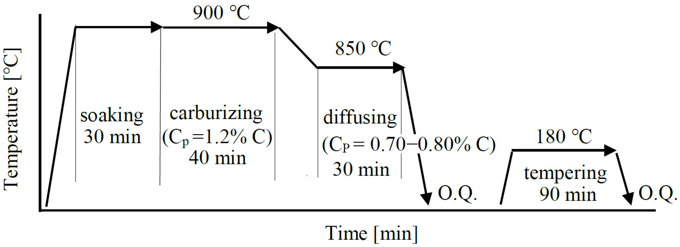
2. Materials and Methods

Steel slabs were vacuum-melted, hot-forged, and hot-rolled into bars with a 13 mm diameter. The chemical composition of the steel slabs is given in Table 1. Round bars 5 mm in diameter and 90 mm in length were machined from the 13 mm bars and ground using Emery paper #2000. Carbon potentials were varied in a range between 0.20 mass % and 0.80 mass %. The heat-treated TM steel [11] which was subjected to quenching to 50 °C, isothermal transformation at 50 °C for 1000 s and partitioning at 350 °C for 1000 s had a carbon potential of 0.20 mass %. The specimens corresponding to a carbon potential range between 0.70 mass % and 0.80 mass % were subjected to vacuum-carburization in enriched gas with various concentrations of hydrocarbons and then quenching in oil at 80 °C followed by tempering at 180 °C for 90 min (Figure 1) in a vacuum-carburizing batch furnace (VCB; IHI Machinery and Furnace Co., Ltd., Tokyo, Japan). For comparison, commercial JIS-SNCM420 steel bars were prepared using the same vacuum-carburization conditions as the TM steel. For SNCM420 steel corresponding to a carbon potential of 0.20 mass %, the heat-treatment of quenching to 50 °C and tempering at 200 °C for 3600 s was conducted.
FPP was carried out on the surface of the cylindrical specimens under the conditions listed in Table 2. According to a previous study [20], these conditions achieve the highest fatigue strength for vacuum-carburized TM and SNCM420 steels. The microstructure of the steels was observed by field emission-scanning electron microscopy (FE-SEM; JSM-6500F, JEOL Ltd., Tokyo, Japan), which was performed using an instrument equipped with an electron backscatter diffraction system (EBSD; OIM system, TexSEM Laboratories, Inc., Draper City, UT, USA). The specimens for the FE-SEM-EBSD analysis were first ground with alumina powder and colloidal silica, then subjected to ion thinning. Vickers hardness was measured by a micro Vickers hardness tester (HVM, Shimadzu Co., Kyoto, Japan). The testing load was 4.9 N. Surface roughness was measured by laser scanning microscopy (LSM; VK-8510, Keyence Co., Milton Keynes, UK) and was evaluated by the maximum roughness height (Rz, JIS B0601:2001).
The volume fraction of the retained austenite phase was quantified from the integrated intensity of the (200)α, (211)α, (200)γ, (220)γ, and (311)γ peaks in the X-ray diffraction pattern (RINT2000, Rigaku Co., Tokyo, Japan) [21]. The cosα method [22] was applied to X-ray studies of residual stress in a longitudinal direction using an X-ray residual stress analyzer (μ-X360, Pulstec Ind. Co. Ltd., Hamamatsu, Japan). The measurement conditions and material constants used are described in detail in [22].

3. Results

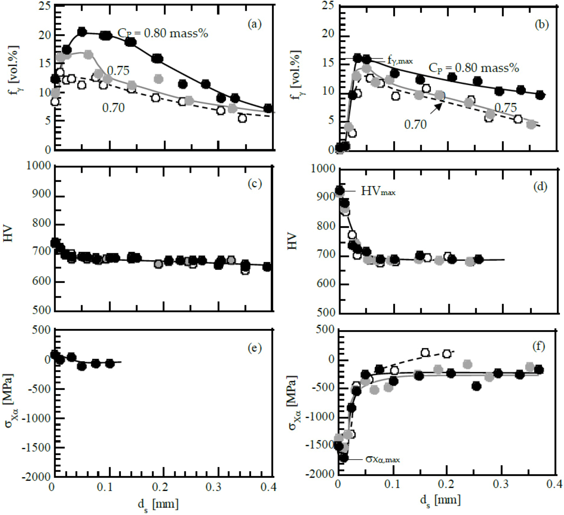
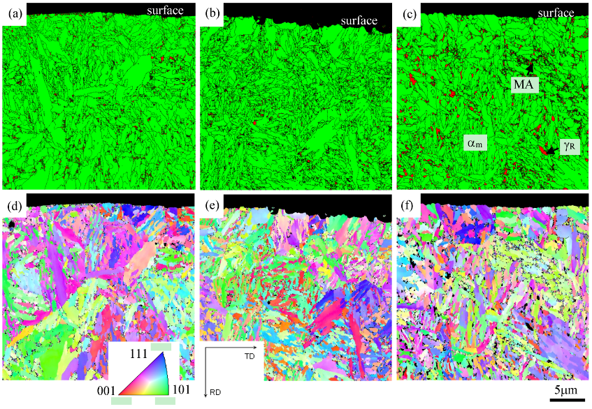
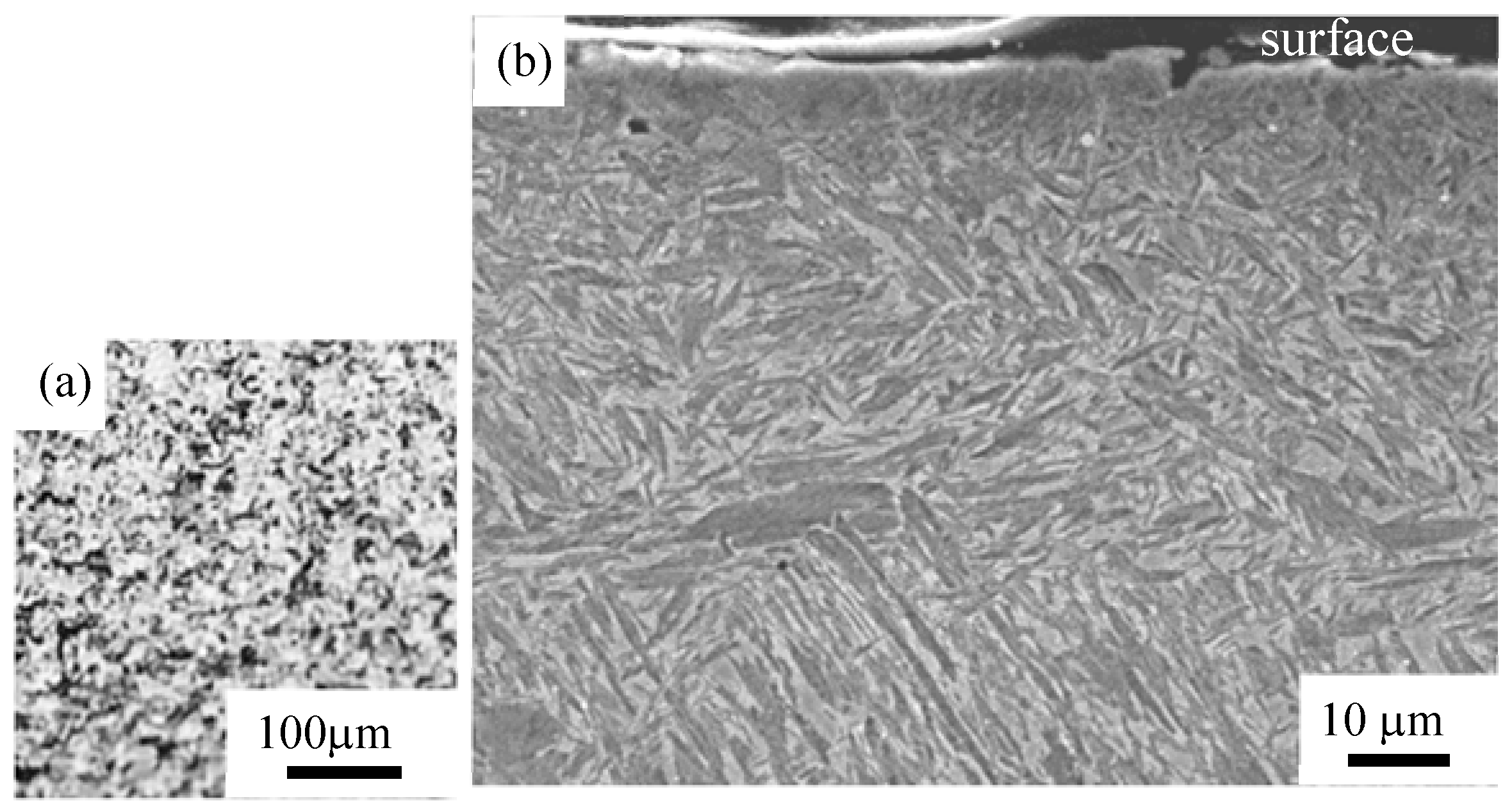
3.1. Surface-Hardened Layer Properties of Vacuum-Carburized Steels

Results from the EBSD analyses of TM steel subjected to vacuum-carburization under various carbon potentials are shown in Figure 2. The microstructure of the TM steel was characterized as having a mixture of α’-martensite structure matrix with wide lath size, martensite-austenite (MA)-like phases and retained austenite islands. Two types of retained austenite were observed; island type of retained austenite isolated in the matrix and filmy type of retained austenite located along fine and narrow martensite lath boundaries in the MA-like phase [2,3]. The volume fractions of the retained austenite and the MA-like phase increased with increasing carbon potential in the TM steel. The TM steel was found to possess a larger amount of retained austenite and a smaller amount of MA-like phase than the SNCM420 steel [19].
Figure 3a,c,e shows the distribution of volume fraction of untransformed retained austenite, Vickers hardness, and X-ray residual stress in the surface-hardened layer of the vacuum-carburized TM steel. The retained austenite fraction and the carburization depth increased with increasing carbon potential in vacuum carburization. The depth from the surface corresponding to the maximum volume fraction of the retained austenite was from 10 μm to 50 μm from the surface. The maximum hardness was determined for the surface and almost the same under carbon potentials from 0.70 mass % to 0.80 mass %. Residual stresses of all specimens were between 0 MPa and 60 MPa. To eliminate complications, residual stress distribution of TM steel was subjected to vacuum-carburization under a carbon potential of 0.80 mass % in Figure 3e.
Figure 4 shows the carbon potential dependences of the maximum retained austenite fraction, hardness, and compressive residual stress. The maximum retained austenite fraction, hardness, and compressive residual stress were strongly dependent on the carbon potential of vacuum-carburization except for the maximum residual stress. The maximum values of retained austenite fraction and Vickers hardness were slightly higher in the TM steel than in the SNCM420 steel [19].

3.2. Surface-Hardened Layer Properties of Vacuum-Carburized and Fine-Particle Peened Steels

A typical top-view LSM image of the surface and a cross-sectional side view SEM image of the surface-hardened layer in vacuum-carburized TM steel subjected to FPP are shown in Figure 5. The microstructure just below the surface is refined in all steels. A white layer (nanostructure or an amorphous structure) [12,23] was not observed on the surface of either steel subjected to FPP. There was no difference in microstructures of the TM steels subjected to vacuum-carburizing under various carbon potentials. Surface roughness of the TM steel ranged from Rz = 5.0 μm to 5.2 μm, which was the same as that of SNCM420 steel.
Figure 3b,d,f shows the distribution of volume fraction of untransformed retained austenite, Vickers hardness, and X-ray residual stress of the α-bcc phase in the surface-hardened layer of the carburized TM steel subjected to FPP. A large amount of retained austenite transformed to martensite on the surface and at depths less than 20 μm from the surface. Consequently, the volume fraction of strain-induced martensite was highest on the surface or at the subsurface region. Hardness was also highest on the surface under all carbon potentials tested. The compressive residual stress was highest right under the surface, at a depth of 10 μm.
The maximum values obtained for the surface-hardened layer properties are listed in Table 3 and their corresponding carbon potential dependences are shown in Figure 4. With increasing carbon potential, the maximum volume fraction of the retained austenite, the maximum hardness, and the maximum compressive residual stress all increased, although the maximum harness under carbon potentials of 0.70 mass % to 0.80 mass % was nearly the same. These maximum values are slightly higher than those of the SNCM420 steel [19]. The maximum volume fraction of strain-induced martensite of the steels subjected to FPP was obtained on the surface or at the subsurface region under all carbon potentials tested.

4. Discussion

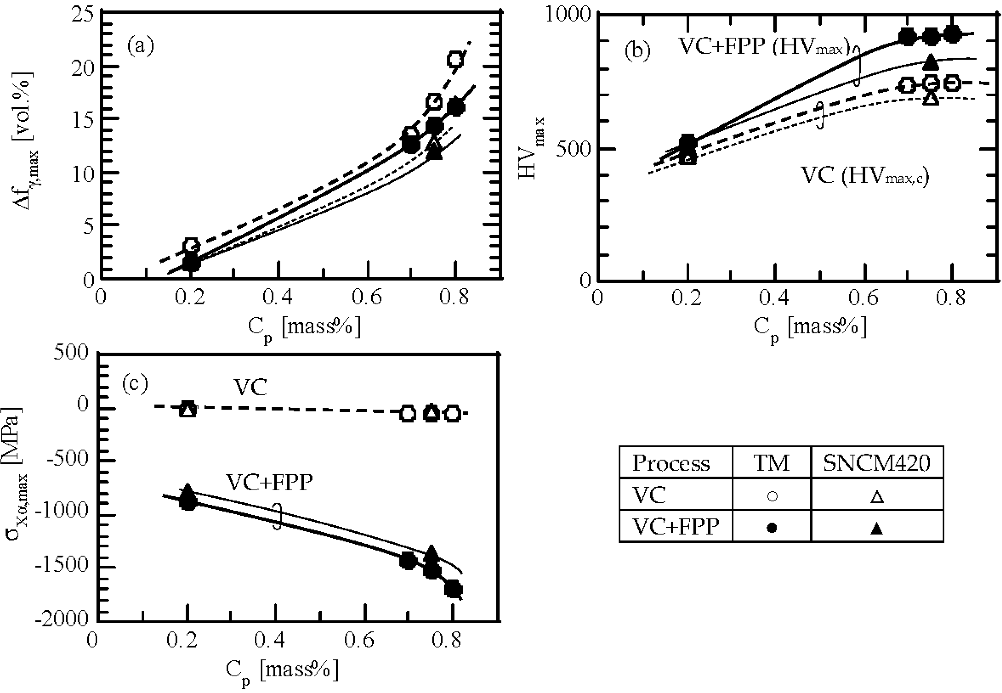
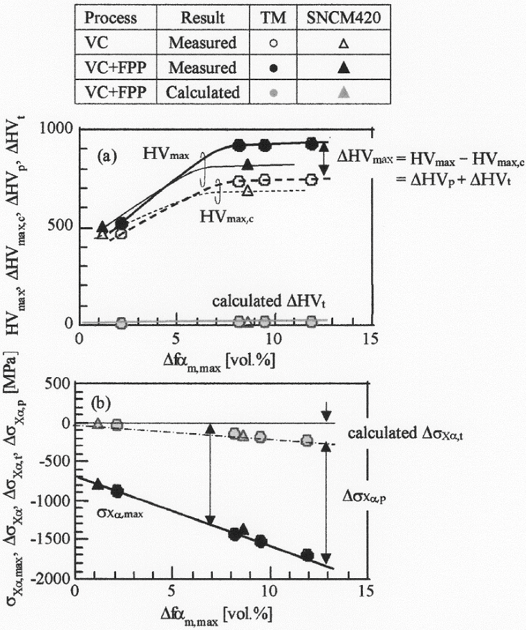
4.1. Maximum Hardness

In general, vacuum-carburization enhances the hardness and volume fraction of retained austenite in the surface-hardened layer, although the retained austenite fraction on the surface is decreased somewhat. Subsequent FPP increases both the hardness and the compressive residual stress in the surface-hardened layer of steels via severe plastic deformation and strain-induced martensitic transformation [3,9,12,14,15,16,17,18,23].
Figure 6a shows the relationship between the maximum hardness and the strain-induced martensite fraction in the TM and SNCM420 steels. An increment in hardness after vacuum-carburization and FPP (ΔHVmax = HVmax − HVmax,c) is the sum of the increments in hardness due to the severe plastic deformation and the strain-induced martensitic transformation (ΔHVmax = ΔHVp + ΔHVt), respectively. HVmax and HVmax,c are Vickers hardness after vacuum-carburization and FPP and after vacuum-carburization, respectively (Table 3). The ΔHVmax increases with increasing strain-induced martensite fraction. ∆HVt can be estimated using Equation (1),
ΔHVt = (HVαm* − HVmax,c) × Δfαm,max,
where Δfαm,max is the maximum volume fraction of strain-induced martensite after FPP (Table 3), HVαm* is Vickers hardness of the strain-induced martensite with carbon concentration in the retained austenite of 0.70−0.80 mass % (Table 4). The carbon concentration of the retained austenite (Cγ = 0.80 mass %) determined in Reference [2] was used as the value for the heat-treated steel, corresponding to carbon potential of 0.20 mass %. Vickers hardness of martensite determined in Reference [24] was substituted as HVαm* in Equation (1). As shown in Figure 6a and Table 4, the calculated ΔHVt values of the TM and SNCM420 steels are between 10 and 21 in a carbon potential range between 0.70 mass % and 0.80 mass %. These values are much smaller than ΔHVmax and the ratios of ΔHVt to ΔHVmax in carburized TM steel subjected to FPP are between 0.05 and 0.11 (Figure 7 and Table 4), although the ratios increase with increasing carbon potential in vacuum-carburization, except for a carbon potential of 0.2 mass %. Therefore, it can be assumed that ΔHVp is much higher than ΔHVt in TM and SNCM420 steels and is the major factor that affects the change in hardness after FPP. In Figure 3d and Figure 4b, the effect of carbon potential on the maximum hardness was negligibly small in a carbon potential range between 0.70 mass % and 0.80 mass %. This may be caused by the low ratio of ΔHVt to ΔHVmax which high hardness of matrix structure weakens the influence of the strain-induced martensite transformation. In Table 4, the ratios of ΔHVt to ΔHVmax in a case of a carbon potential of 0.2 mass % were relatively high (0.23 to 0.25). This is associated with low hardness of matrix structure, and it differs from the cases of high carbon potentials.

4.2. Maximum Compressive Residual Stress

If the compressive residual stress after vacuum-carburization can be ignored, as it is very low compared to hardness, it is possible to divide the maximum compressive residual stress into contributions from severe plastic deformation and strain-induced martensite transformation. In Equation (2), we can approximate the residual stress mainly resulting from the strain-induced martensite transformation during FPP.
According to the previous works [25,26], if transformation strain of the martensite islands is assumed to be an isotropic expansion, the transformation strain (eM*) of the Fe-0.19-1.01%C steels at martensite-start temperature is given by:
eM* = 0.0058 + 0.0043 × %C,
where %C is carbon concentration of the martensite. Natori et al. [27] proposed that residual stress resulting from the strain-induced martensitic transformation (ΔσXα,t) can be calculated using Equation (3),
ΔσXα,t = −(d0dA) × Δfαm,max × E × eM*/d0,
where d0 and dA are an original diameter of specimen and the depth of the surface-hardened layer, respectively. E is the Young’s modulus. In the heat-treated TM steel, eM* was calculated to be 0.0092 because the %C can be estimated to be 0.8 mass % [11]. In the TM steel subjected to vacuum-carburization under carbon potentials of 0.70 mass %, 0.75 mass % and 0.80 mass %, eM*s are 0.0088, 0.0090 and 0.0092, respectively. Substituting d0 = 5 mm, dA = 0.02 mm, Δfαm,max (Table 3), and E = 206 GPa into Equation (3), ΔσXα,t can be calculated as shown in Figure 6b and Table 4. The calculated ΔσXα,t values for TM and SNCM420 steels linearly increase with the carbon potential, in the same manner as the maximum compressive residual stress (σXα,max). The ΔσXα,t values, however, are much smaller than σXα,max and the ratios of ΔσXα,t to ΔσXα,max of vacuum-carburized TM steel are between 0.10 and 0.13 (Figure 7 and Table 4), although the ratios increase with increasing carbon potential of vacuum carburization. Therefore, high compressive residual stress is likely to be caused by the compressive residual stress, primarily due to large plastic strain (ΔσXα,p = ΔσXα,max − ΔσXα,t). In addition, it is considered that the ΔσXα,t mainly brought on the carbon potential dependence of the maximum compressive residual stress, in connection with that of the strain-induced martensite fraction.

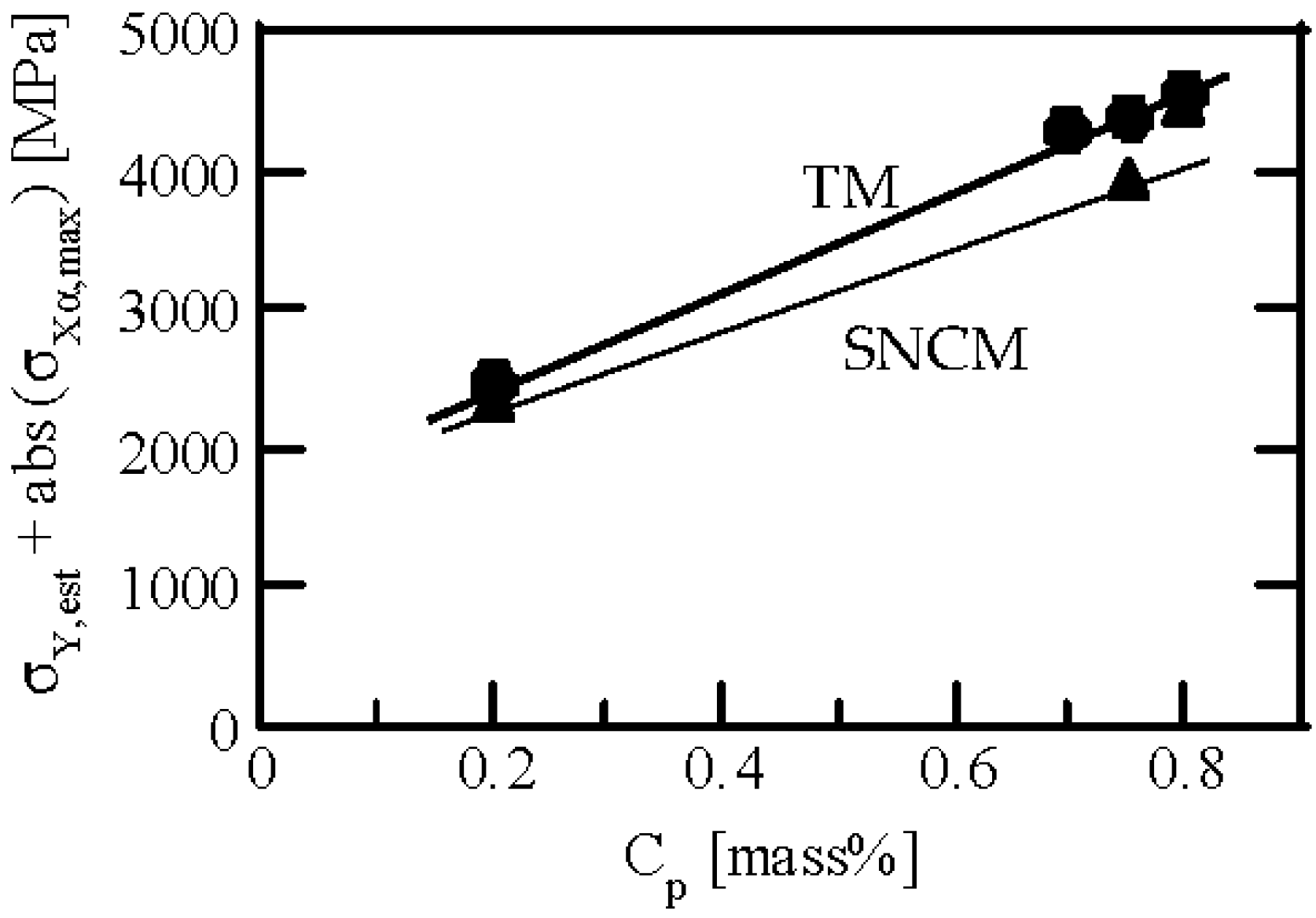
4.3. Estimation of Fatigue Limit

Matsui et al. [14,15] reported that the sum of estimated yield stress (σY,est) and the absolute value of maximum compressive residual stress {abs(σXα,max)} is related to the rotational bending fatigue limit (σw) of gas-carburized steel subjected to shot peening, as follows:
σw = 0.3891 × {σY,est + abs(σXα,max)},
where the value of σY,est can be estimated from HVmax by:
σY,est = (HVmax/3) × 9.80665 × (YS/TS),
where YS/TS is the yield ratio defined by the ratio of yield stress to tensile strength (assumed by Matsui et al. [14,15] to be 0.95).
Figure 8 shows the relationship between σY,est + abs(σXα,max) and carbon potential of vacuum-carburization for the TM and SNCM420 steels. The value of σY,est + abs(σXα,max), given in Table 4, increases with increasing carbon potential in both steels, although the values for TM steel are higher than for SNCM420 steel. This indicates that the fatigue limits of both steels are increased by vacuum-carburization under high carbon potential. In general, the fatigue limit of ultrahigh strength steel is also controlled by the initiation depth of fish-eye cracks. The relationship between σw and σY,est + abs(σXα,max) is described in detail elsewhere [28].

5. Summary

The effects of the carbon potential of vacuum-carburization on the surface-hardened layer properties of a 0.2%C-1.5%Si-1.5%Mn-1.0%Cr-0.05%Nb TM steel were investigated for the fabrication of precision gears. The main results can be summarized as follows:
(1)
Vacuum-carburization resulted in a large amount of retained austenite and high Vickers hardness in the surface hardened layer of the steel with a low residual stress from 0 MPa to 60 MPa. The retained austenite fraction and the hardness increased with increasing carbon potential during vacuum-carburization, although the residual stress was independent of the carbon potential.
(2)
Subsequent FPP enhanced the compressive residual stress and the volume fraction of strain-induced martensite, especially in the surface hardened layer, with a further increase in hardness. These surface-hardened layer properties improved with increasing carbon potential.
(3)
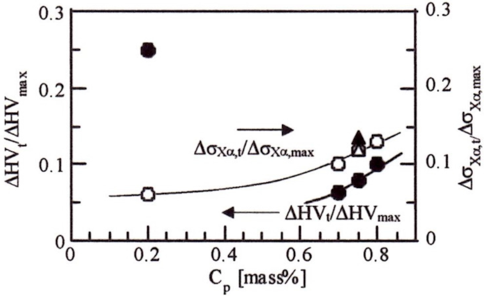
The severe plastic deformation upon FPP treatment was the main contributor to hardness and compressive residual stress in the surface-hardened layer. The role of FPP in the strain-induced transformation on the hardness and the residual stress was relatively small, compared to that in the case of severe plastic deformation.

Acknowledgments

This study was supported by a Grant-in-Aid for Scientific Research (B), The Ministry of Education, Science, Sports and Culture, Japan (No. 2013-25289262). We also thank Yuji Kobayashi from Sintokogio Ltd. for fine-particle peening, Company Executive Kuniharu Nishizawa from Okaya Heat Treatment Co., Ltd. for vacuum carburization, and Editage (www.editage.jp) for English language editing.

Author Contributions

Koh-ichi Sugimoto was the main contributor to this work. He mainly analyzed the data and made the draft of the research paper; Tomohiko Hojo and Yuta Mizuno performed the experimental work and proofread the paper.

Conflicts of Interest

The authors declare no conflict of interest.

References

  1. Maniwa, K.; Obara, S.; Kurogi, J.; Kanai, S.; Ueura, K. Improvement of Lubrication Life of Strain Wave Gearing for Space Applications by Surface Carburizing. In Proceedings of the 5th World Tribology Congress (WTC 2013), Torino, Italy, 8–13 September 2013. [Google Scholar]
  2. Kobayashi, J.; Song, S.; Sugimoto, K. Ultra-high-strength TRIP-aided martensitic steels. ISIJ Int. 2012, 52, 1124–1129. [Google Scholar] [CrossRef]
  3. Sugimoto, K.; Srivastava, A.K. Microstructure and mechanical properties of a TRIP-aided martensitic steel. Metallogr. Microstruct. Anal. 2015, 4, 344–354. [Google Scholar] [CrossRef]
  4. Sugimoto, K.; Hojo, T. Fatigue hardening behavior of a 1.5 GPa Grade TRIP-aided martensitic steel. Metall. Mater. Trans. A 2016, 47, 5272–5279. [Google Scholar] [CrossRef]
  5. Diego-Calderon, I.; Rodriguez-Calvillo, P.; Lara, A.; Molina-Aldareguia, J.M.; Petrov, R.H.; De Knijf, D.; Sabirov, I. Effect of microstructure on fatigue behavior of advanced high strength steels produced by quenching and partitioning and the role of retained austenite. Mater. Sci. Eng. A 2015, 641, 215–224. [Google Scholar] [CrossRef]
  6. Gao, G.; Zhang, B.; Cheng, C.; Zhao, P.; Zhang, H.; Bai, B. Very high cycle fatigue behaviors of bainite/martensite multiphase steel treated by quenching-partitioning-tempering process. Int. J. Fatigue 2016, 9, 203–210. [Google Scholar] [CrossRef]
  7. Mueller, I.; Rementeria, R.; Caballero, F.G.; Kuntz, M.; Sourmail, T.; Kerscher, E. A constitutive relationship between fatigue limit and microstructure in nanostructured bainitic steels. Materials 2016, 9, 831. [Google Scholar] [CrossRef]
  8. Zhang, P.; Zhang, F.; Yan, Z.; Wang, T.; Qian, L. Wear property of low-temperature bainite in the surface layer of a carburized low carbon steel. Wear 2011, 271, 697–704. [Google Scholar] [CrossRef]
  9. Kobayashi, J.; Yoshikawa, N.; Sugimoto, K. Notch-fatigue strength of advanced TRIP-aided martensitic steels. ISIJ Int. 2013, 53, 1479–1486. [Google Scholar] [CrossRef]
  10. Sugimoto, K.; Mizuno, Y.; Hojo, T. Effect of fine particle peening on fatigue strength of a TRIP-aided martensitic steel. Key Eng. Mater. 2016, 665, 85–88. [Google Scholar] [CrossRef]
  11. Sugimoto, K.; Mizuno, Y.; Natori, M.; Hojo, T. Effects of fine particle peening on fatigue strength of a TRIP-aided martensitic steel. Int. J. Fatigue 2017, 100, 206–214. [Google Scholar] [CrossRef]
  12. Bagherifard, S.; Guagliano, M. Fatigue behavior of a low-alloy steel with nanostructured surface obtained by severe shot peening. Eng. Fract. Mech. 2012, 81, 56–68. [Google Scholar] [CrossRef]
  13. Dalaei, K.; Karlsson, B.; Svensson, L.E. Stability of shot peening induced residual stresses and their influence on fatigue lifetime. Mater. Sci. Eng. A 2011, 528, 1008–1015. [Google Scholar] [CrossRef]
  14. Koshimune, M.; Matsui, K.; Takahashi, K.; Nakano, W.; Ando, K. Influence of hardness and residual stress on fatigue limit for high strength steel. Trans. Jpn. Soc. Spring Eng. 2009, 54, 19–26. [Google Scholar] [CrossRef]
  15. Matsui, K.; Koshimune, M.; Takahashi, K.; Ando, K. Influence of shot peening method on rotating bending fatigue limit for high strength steel. Trans. Jpn. Soc. Spring Eng. 2010, 55, 7–12. [Google Scholar] [CrossRef]
  16. Kato, M.; Matsumura, Y.; Ishikawa, R.; Kobayashi, Y. Influence of shot peening condition on the fatigue strength of the carburizing steel. Electr. Furn. Steel 2008, 79, 69–76. [Google Scholar] [CrossRef]
  17. Shaw, B.A.; Aylott, C.; O’Hara, P.; Brimble, K. The role of residual stress on the fatigue strength of high performance gearing. Int. J. Fatigue 2003, 25, 1279–1283. [Google Scholar] [CrossRef]
  18. Davies, D.P.; Jenkins, S.L. Influence of stress and environment on the fatigue strength and failure characteristics of case carburized low alloy steels for aerospace applications. Int. J. Fatigue 2012, 44, 234–244. [Google Scholar] [CrossRef]
  19. Sugimoto, K.; Hojo, T.; Mizuno, Y. Surface-hardened layer properties of newly developed case-hardening steel. ISIJ Int. 2017. submitted for publication. [Google Scholar]
  20. Sugimoto, K.; Hojo, T.; Mizuno, Y. Effects of fine particle peening conditions on rotational bending fatigue strength of a vacuum carburized TRIP-aided martensitic steel. Metall. Mater. Trans. A 2017. submitted for publication. [Google Scholar]
  21. Maruyama, H. X-ray measurement of retained austenite volume fraction. J. Jpn. Soc. Heat Treat. 1977, 17, 198–204. [Google Scholar]
  22. Maruyama, Y.; Miyazaki, T.; Sasaki, T. Development and validation of an X-ray stress measurement device using an imaging plate suitable for the cosα method. J. Soc. Mater. Sci. Jpn. 2015, 64, 560–566. [Google Scholar] [CrossRef]
  23. Umemoto, M. Nanocrystallization of steels by severe plastic deformation. Mater. Trans. 2003, 44, 1900–1911. [Google Scholar] [CrossRef]
  24. Tamura, I. Strength of Steels; Nikkan-Kogyo-Shimbun Ltd.: Tokyo, Japan, 1969; p. 133. [Google Scholar]
  25. Moyer, J.M.; Ansell, G.S. The volume expansion accompanied the martensite transformation in Iron-carbon alloys. Metall. Trans. A 1975, 6, 1785–1792. [Google Scholar] [CrossRef]
  26. Sakaki, T.; Sugimoto, K.; Fukuzato, T. Role of internal stress for continuous yielding of dual-phase steels. Acta Metall. 1983, 31, 1737–1746. [Google Scholar] [CrossRef]
  27. Natori, N.; Song, S.; Sugimoto, K. The effects of fine particle peening on surface residual stress of a TRIP-aided bainitic ferrite steel. J. Soc. Mater. Sci. Jpn. 2014, 63, 662–668. [Google Scholar] [CrossRef]
  28. Sugimoto, K.; Hojo, T.; Mizuno, Y. Effects of vacuum carburizing conditions on fatigue strength of a TRIP-aided martensitic steel. Mater. Sci. Technol. 2017. submitted for publication. [Google Scholar]
Figure 1. Vacuum-carburization and tempering diagram, in which “O.Q.” represents quenching in oil at 80 °C, CP is carbon potential.
Metals 07 00301 g001
Figure 2. (ac) Phase maps and (df) orientation maps of the α-bcc phase of a cross-sectional side view of the surface-hardened layer of transformation-induced TRIP-aided martensitic (TM) steel subjected to vacuum-carburization under various carbon potentials of (a,d) CP = 0.70 mass %, (b,e) CP = 0.75 mass % and (c,f) CP = 0.80 mass %. In (ac), yellowish green, gray and red regions represent the α’-martensite (αm) matrix, MA-like (MA) phase and retained austenite (γR) islands, respectively.
Metals 07 00301 g002
Figure 3. Variations in (a,b) volume fraction of retained austenite (fγ), (c,d) Vickers hardness (HV), and (e,f) X-ray residual stress in the α-bcc phase (σ) as a function of depth from the surface (ds) in TM steel subjected to vacuum-carburization under carbon potentials of 0.70 mass % (○), 0.75 mass % () and 0.80 mass % (●). (a,c,e): After vacuum-carburization, (b,d,f): After vacuum-carburization and fine-particle peening.
Metals 07 00301 g003
Figure 4. Variations in (a) maximum volume fraction of the retained austenite (fγ,max), (b) maximum hardness (HVmax), and (c) maximum compressive residual stress (σXα,max) as a function of carbon potential (CP) in TM (○●, thick lines) and SNCM420 (△▲, thin lines) steels after vacuum-carburization (VC) or after vacuum carburization and subsequent fine-particle peening (VC + FPP). HVmax,c is HVmax of as-vacuum-carburized steels.
Metals 07 00301 g004
Figure 5. Typical (a) laser scanning microscopy (LSM) image of the top-view of the surface and (b) SEM image of the cross-sectional side view of the surface-hardened layer of the TM steel subjected to vacuum-carburization under a carbon potential of 0.8 mass % and subsequent fine-particle peening.
Metals 07 00301 g005
Figure 6. Relationships between (a) Vickers hardness and (b) residual stress properties and maximum volume fraction of strain-induced martensite (Δfαm,max) in TM (●○) and SNCM420 (▲Δ) steels. HVmax: Maximum hardness after vacuum-carburization and fine-particle peening (VC + FPP); HVmax,c: Maximum hardness after vacuum-carburization (VC); ΔHVmax, ΔHVp and ΔHVt: Increments of hardness due to fine-particle peening, the severe plastic deformation and the strain-induced martensitic transformation, respectively; σXα,max: Maximum compressive residual stress after vacuum carburization and fine-particle peening; ΔσXα,max, ΔσXα,p, and ΔσXα,t: Increments in σXα,max due to fine-particle peening, calculated compressive residual stresses due to the severe plastic deformation and estimated compressive residual stress due to the strain-induced martensitic transformation, respectively.
Metals 07 00301 g006
Figure 7. Variations in ΔHVt/ΔHVmax and ΔσXα,tσXα,max as a function of carbon potential in vacuum-carburization (CP) in TM (○●) and SNCM420 (Δ▲) steels subjected to fine-particle peening.
Metals 07 00301 g007
Figure 8. Relationship between the sum of the estimated yield stress and the absolute value of maximum compressive residual stress {σY,est + abs(σXα,max)} and carbon potential in vacuum-carburization (CP) in TM (●) and SNCM420 (▲) steels subjected to fine-particle peening.
Metals 07 00301 g008
Table 1. Chemical composition [mass %] of the steels used in this study. TM: TRIP-aided martensitic.
SteelCSiMnPSCrMoNiAlNbN
TM0.201.501.510.0050.0021.000.010.020.0390.050.0009
SNCM4200.200.200.500.0090.0130.550.151.68---
Table 2. Fine-particle peening conditions.
Shot MaterialSteel
Shot Vickers hardness900
Shot diameter (μm)50
Pressure modeAir nozzle
Arc height (mm (N))0.21
Coverage (%)300
Table 3. Measured surface-hardened layer properties of TM and SNCM420 steels subjected to vacuum-carburization under various carbon potentials and subsequent fine-particle peening.
SteelCPRzfγ,maxΔfαm,maxHVmax,cHVmaxσXα,max
TM0.203.03.12.2473525−863
0.705.112.78.2733921−1429
0.755.014.39.5740920−1509
0.805.216.111.9740928−1683
SNCM4200.203.31.61.1469504−792
0.755.012.08.6694824−1361
CP (mass %): Carbon potential in vacuum-carburization; fγ,max (vol %): Maximum untransformed retained austenite; Δfαm,max (vol %): Maximum strain-induced martensite fraction; HVmax,c: Maximum Vickers hardness after vacuum-carburization; HVmax: Maximum Vickers hardness; σXα,max (MPa): Maximum compressive residual stress.
Table 4. Estimated surface-hardened layer properties of TM and SNCM420 steels subjected to vacuum-carburization under various carbon potentials and subsequent fine-particle peening.
SteelCPCγHVαm*ΔHVtΔHVt/ΔHVmaxeM*ΔσXα,tΔσXα,t/ΔσXα,maxσY,estσY,est + abs(σXα,max)
TM0.200.80880–92012–130.23–0.250.0092−550.0616302493
0.700.70850–92010–150.05–0.080.0088−1480.1028604289
0.750.75865–92012–170.07–0.090.0090−1750.1228574366
0.800.80880–92017–210.09–0.110.0092−2240.1328824565
SNCM4200.20----0.0067−120.0215652357
0.750.75865–92015–190.12–0.150.0090−1590.1225593920
CP (mass %): Carbon potential; Cγ (mass %): Carbon concentration in the retained austenite; HVαm*: Vickers hardness of strain-induced martensite; ∆HVt: Increment in Vickers hardness resulting from strain-induced martensite transformation; ΔHVmax: Increment of HVmax due to fine-particle peening; eM*: Transformation strain; ∆σXα,t (MPa): Residual stress calculated from martensitic transformation strain; ΔσXα,max (MPa): Increment in σXα,max due to fine-particle peening; σY,est (MPa): Estimated yield stress; abs (σXα,max) (MPa): Absolute value of the maximum residual stress.

