Preparing Ferro-Nickel Alloy from Low-Grade Laterite Nickel Ore Based on Metallized Reduction–Magnetic Separation


School of Metallurgy, Northeastern University, Shenyang 110819, China
*
Author to whom correspondence should be addressed.
Metals 2017, 7(8), 313; https://doi.org/10.3390/met7080313
Submission received: 9 July 2017
/
Revised: 9 August 2017
/
Accepted: 12 August 2017
/
Published: 16 August 2017
Abstract
:Nickel, a valued metal, mainly exists as nickel oxide in laterite nickel ore. Furthermore, a large part of the laterite nickel ore is low-grade saprolitic ore. In this paper, a research on preparing ferro-nickel alloy from low-grade saprolitic laterite nickel ore using metallized reduction-magnetic separation was studied. In the research, the carbothermic reductions of iron oxide and nickel oxide were analyzed in terms of thermodynamics. The influences of reduction temperature, reduction time, carbon ratio, and CaO addition on the recoveries and grades of iron and nickel were experimentally investigated. To analyze and clarify the related mechanism, the microstructure of ferro-nickel alloy was observed by optical microscope (OM) and scanning electron microscope/energy dispersive spectrometer (SEM/EDS). Accordingly, the results showed that, increasing reduction temperature can improve the grades and recoveries of nickel and iron; appropriate reduction time, carbon ratio and CaO addition can favor aggregation and growing up of the ferro-nickel particles, improving the grades and recoveries of nickel and iron. The optimal process parameters obtained were a reduction temperature of 1350 °C, reduction time of 2 h, carbon ratio of 1.2, and CaO addition of 10%. In this case, the ferro-nickel alloy with nickel grade 7.90% and iron grade 77.32% was prepared successfully from the low-grade saprolitic ore with nickel content 1.82%. The nickel and iron recoveries were 89.36% and 95.87% respectively, which achieved the highly efficient recovery and utilization of iron and nickel of low-grade laterite nickel ore.
1. Introduction
Nickel, an important strategic metal resource with the properties of anticorrosion, antiabrasion, and thermostability, has been widely used in stainless steel, special alloy steel, and other areas [1,2]. Nickel ore is divided into 30% nickel sulfide ore and 70% nickel oxide ore (most is laterite nickel ore), but almost 60% of nickel products come from nickel sulfide ore at present [3,4,5,6]. With the shortage of sulfide ore, the increasing demand for nickel, and the great progress in metallurgical technology, the development and utilization of laterite nickel ore has been attracted great attention [7]. Laterite nickel ore, generated during laterization (the weathering process by which soil and rock are changed to laterite in hot and wet tropical areas) [8,9], is chemically and physically divided into two distinct types, namely limonitic laterite nickel ore and saprolitic laterite nickel ore [10]. However, the two different type ores are always found together, with the limonitic portion generally overlaying the saprolitic. In limonitic laterite nickel ore, the contents of iron and cobalt are high, while that of silicon, magnesium, and nickel are low, which is appropriately beneficiated by hydrometallurgical processes, such as reducing roasting-ammoniac leaching, high pressure acid leaching (HPAL), and heap leaching (HL). In saprolitic laterite nickel ore, the contents of silicon, magnesium and nickel are high, while that of iron and cobalt are low, which is appropriately treated by pyrometallurgical processes, such as rotary kiln-electric furnace process (RKEF) and blast furnace processes.
Furthermore, the saprolitic ore is divided into high-grade saprolitic laterite nickel ore and low-grade saprolitic laterite nickel ore (the grade of Ni is less 2.4% [11]) from the perspective of Ni grade. The treatment processes of high-grade saprolitic ore have been comprehensively researched and extensively utilized [12,13,14,15]. Low-grade saprolitic ore, was mainly treated using pyrometallurgical processes, for instance, RKEF, chlorinated segregation-magnetic separation [16], and metallized reduction-magnetic separation [17]. By contrast, the RKEF process is high energy consumption and the chloridizing agent (Cl2, NaCl, and CaCl2) can cause heavy environmental pollution, hence, the metallized reduction-magnetic separation process is a good choice. The first rotary kiln reduction-magnetic separation process, the Krupp-Renn process, was used to produce luppen (iron particle) in the 1930s. This process used coal as reductant instead of coke or electric energy, significantly saving production cost. The Nippon Yakin plant in Oheyama improved this process to produce ferro-nickel alloy [18,19,20], since the improved process is simple, cost-saving, and has low energy consumption. However, although many researches of metallized reduction-magnetic separation to deal with laterite nickel ore have been done currently, there is little referenced data available for producing and applying ferro-nickel alloy in China because some pivotal parameters are not given due to the commercially confidential information.
Additionally, the ore-coal composite agglomerate technique, an important means to treat composite ores, is widely used due to the close arrangement of ores and carbonaceous materials, saving energy consumption and production costs [21,22,23]. The traditional composite agglomerate technique is cold-bonded composite. In recent years, as a new kind of composite agglomerate technique, the hot briquette technique [24,25,26,27] is investigated. In contrast with the traditional cold-bonded composite, hot briquette owns better reducing property, lower cost, and higher strength, due to exploiting the thermal plasticity of pulverized coal well [28,29,30]. Therefore, applying the hot briquette technique to treat low-grade saprolitic ore would obtain better effectiveness.
Upon the above background, a metallized reduction-magnetic separation process based on hot briquetting was proposed to treat low-grade saprolitic ore in this paper. The process parameters of reduction temperature, reduction time, carbon ratio, and CaO addition were experimentally investigated in order to improve the recoveries and grades of iron and nickel. The ferro-nickel particles were observed by optical microscope (OM) and scanning electron microscope/energy dispersive spectrometer (SEM/EDS) to analyze the mechanism of the microstructure and phase. The characteristics of slag with CaO addition, including composition, melting start temperature, liquidus temperature, liquid generation ratio, and viscosity were calculated by Factsage 7.0 software (Version 7.0, co-presented by CRCT-ThermFact (Montreal, QC, Canada) and GTT-Technologies (Aachen, Germany), 2001). The paper provides a reference for the research and utilization of low-grade saprolitic laterite nickel ore.
2. Experiment
2.1. Raw Materials
Raw materials included low-grade saprolitic laterite nickel ore, coal, and CaO. The chemical composition of the low-grade saprolitic laterite nickel ore, as measured by chemical titration, is shown in Table 1. Figure 1 shows the XRD image of this obtained by an X-ray diffractometer (MPDDY2094, PANalytical B.V., Almelo, The Netherlands). Copper Kα radiation (40 kV, 40 mA, wave length 0.154 nm) was used as the X-ray source and the scanned angular range varied from 5° to 90° with a scanning speed of 0.2°/s. The results indicated that nickel grade was 1.82% and existed mainly in the form of chlorite (Ni3Si2O5(OH)4) and garnierite ((Ni,Mg)3Si2O5(OH)4). Iron grade was 19.57%, and it existed as chrysotile ((Mg,Fe)3(Si,Al)3O7(OH)4), goethite (FeOOH), and hematite (Fe2O3). Silicon and magnesium grades, which negatively affect nickel and iron recoveries, were relatively high. The industrial compositions of the coal is listed in Table 2. The additive CaO was used as an analytical reagent.
2.2. Experimental Procedure
The experimental procedure is shown as Figure 2. Firstly, raw ore was dried at 105 °C for 2 h and then was crushed by a jaw crusher to 100% passing 2 mm. Coal was dried at 90 °C and was ground by a 2-MZ centrifugal grinding machine to 100% passing 74 μm. Secondly, the crushed ore, coal powder and CaO reagent were uniformly mixed into mixed sample with a certain proportion. The about 7 g mixed sample was input into the mold to be heated to 300 °C , and then was briquetted with a pressure of 50 MPa to form a spheroidicity briquette named low-grade saprolitic laterite nickel ore carbon composite hot briquette (shorted as LSLN-CCB, 21 × 19 × 15 mm3). Thirdly, the 10 LSLN-CCBs were put into a crucible in tube furnace shown in Figure 3, and then were heated up to reduction temperature with MoSi2 heating elements. The temperature was measured by thermocouple. Inert atmosphere was maintained by blowing argon gas at a flow rate of 5 L/min. At last, after reduction, the reduction product was quenched in water and was ground into powder sample. The powder sample was separated by a DTCXG-ZN50 magnetic tube at a magnetic flux density of 50 mT [31]. The magnetic product obtained after separation is ferro-nickel alloy.
In the experiments, four parameters were optimized in sequence. The original experimental parameters were reduction temperature 1300 °C, reduction time 2 h, carbon ratio 1.0 and no CaO addition. First, the effects of reduction temperature with a range from 1300 to 1400 °C was investigated to find the optimal reduction temperature. Second, based on the first optimal parameter, the reduction time was optimized from 2 to 6 h. Then, the appropriate carbon ratio, which is the mole ratio of fixed carbon in coal to reducible oxygen of iron and nickel in ore (FC/O), was determined from 1.0 to 1.6. Finally, the optimal CaO addition with a range from 5% to 15% was searched out. The specific parameters are shown in Table 3.
To obtain the experimental data, the nickel and total iron grades in reduction product and in magnetic product, respectively were analyzed by chemical titration analysis. The nickel recovery was calculated according to the following equation:
where RNi is the nickel recovery; mNi is the mass of the magnetic product; MNi is the mass of the reduction product; βNi is Ni grade in magnetic product; γNi is Ni grade in reduction product. The calculation of iron recovery is similar.
To analyze and clarify the related mechanism, the microstructure of ferro-nickel alloy in reduction product was observed by optical microscope (Axio Imager M2m, Carl Zeiss AG, Oberkochen, Germany). The microstructure of ferro-nickel alloy in magnetic product was analyzed by the SEM (Ultra Plus, Carl Zeiss AG, Oberkochen, Germany). The compositions of several spots in magnetic product were also analyzed by EDS (Ultra Plus, Carl Zeiss AG, Oberkochen, Germany).
2.3. Thermodynamic Analysis
Generally, some valuable metal oxides, for instance iron oxide and nickel oxide, can be reduced into metal or protoxide. Nickel oxide mainly exists as NiO in laterite nickel ore. In coal-based reduction, iron oxide is difficult to react with solid carbon, but solid carbon can be reduced by carbon gasification reduction (Equation (9)) under high temperature to produce reducing gas, with which iron oxide processes reduction reaction [32]. The reduction mechanism of iron and nickel oxides is expressed by the following equations [33,34]:
NiO(s) + C(s) = Ni(s) + CO(g) T ≥ 710 K
NiO(s) + CO(g) = Ni(s) + CO2(g) T ≥ 298 K
3Fe2O3(s) + C(s) = 2Fe3O4(s) + CO(g) T ≥ 593 K
3Fe2O3(s) + CO(g) = 2Fe3O4(s) + CO2(g) T ≥ 298 K
Fe3O4(s) + C(s) = 3FeO(s) + CO(g) T ≥ 973 K
Fe3O4(s) + CO(g) = 3FeO(s) + CO2(g) T ≥ 830 K
FeO(s) + C(s) = Fe(s) + CO(g) T ≥ 973 K
FeO(s) + CO(g) = Fe(s) + CO2(g) T ≤ 830 K
C(s) + CO2(g) = 2 CO(g) T ≥ 973 K.
Figure 4 shows the standard Gibbs free energy changes from 400 to 1500 K in the reaction. The carbon gasification reduction (Equation (9)) can occur at temperatures above 973 K. Iron oxide and nickel oxide can be reduced by carbon directly (Equations (1), (3), (5), and (7)) and indirectly (Equations (2), (4), (6), and (8)). Indirect reduction (Equations (2), (4), and (8)) mainly occur at temperatures below 973 K, while direct reduction (Equations (1), (3), (5), and (7)) mainly occur at temperatures above 973 K. During reduction, the reactions of Fe2O3 to Fe3O4 described by Equation (3) occur easily at temperatures above 593 K. Then NiO could be reduced by solid carbon at temperatures above 710 K, as described by Equation (1). The Equations (2) and (4) would hardly occur until the temperature is above 973 K, which is attributable to the generation of CO gas. With descriptions of Equations (5) and (6), Fe3O4 could be reduced when the temperature is over 973 K. The reactions described by Equation (7) occur above 973 K, FeO was reduced to metal iron (MFe), while Equation (8) is hard to occur because there is little CO gas generated at a temperature below 830 K. The nickel oxide can be reduced prior to iron oxides, which is only after the reduction of Fe2O3 to Fe3O4, and nickel oxide reduction could be selectively controlled by changing the reduction temperature. Therefore, from the perspective of thermodynamics, nickel oxide can be reduced all and ferro-nickel alloy can be prepared using this metallized reduction-magnetic separation process.
3. Results and Discussion
3.1. Effects of Reduction Temperature
The effects of reduction temperature on the metallized reduction–magnetic separation of low-grade saprolitic laterite ore was shown in Figure 5. When the temperature increased from 1300 to 1400 °C, the nickel recovery increased sharply from 52.67% to 76.02%, and then rose slowly from 76.02% to 76.45%, with a turning point of 76.02% at 1350 °C; the iron recovery first raised fast from 62.82% to 79.88%, then after 1350 °C, increased slightly from 79.88% to 82.36%; the nickel grade and iron grade showed upward trends, from 4.97% to 5.98% and from 55.74% to 64.28%, respectively. As the reduction temperature increased, the grades and recoveries of nickel and iron were promoted. The appropriate reduction temperature should not be less than 1350 °C.
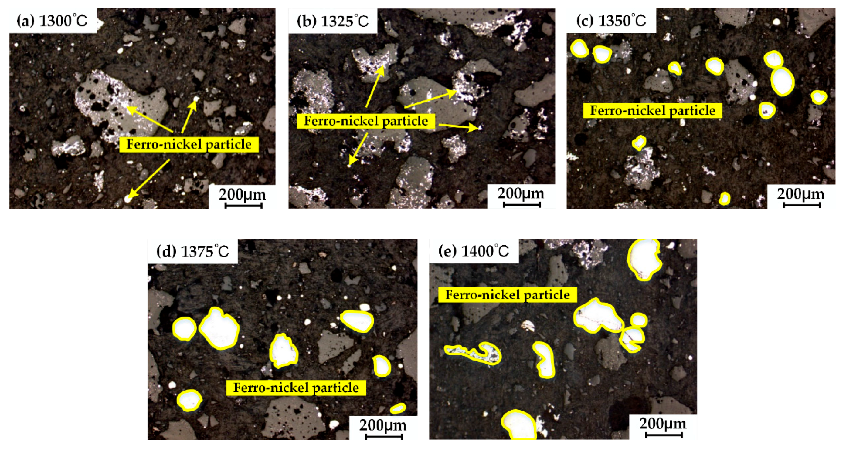
Figure 6 shows the ferro-nickel particles microstructure of reduction product under different reduction temperatures by optical microscope. When at a low temperature, the reduction was slow and the ferro-nickel particles were tiny, resulting in difficult magnetic separation. As temperature increased, the sufficient reduction of nickel and iron made ferro-nickel particles easy to aggregate and enlarge, which favors magnetic separation. The grades and recoveries of nickel and iron increased as a result. However, the nickel recovery slowed down to a constant due to the effect of temperature on recovery was inconspicuous after 1350 °C. Therefore, the appropriate reduction temperature is 1350 °C.
3.2. Effects of Reduction Time
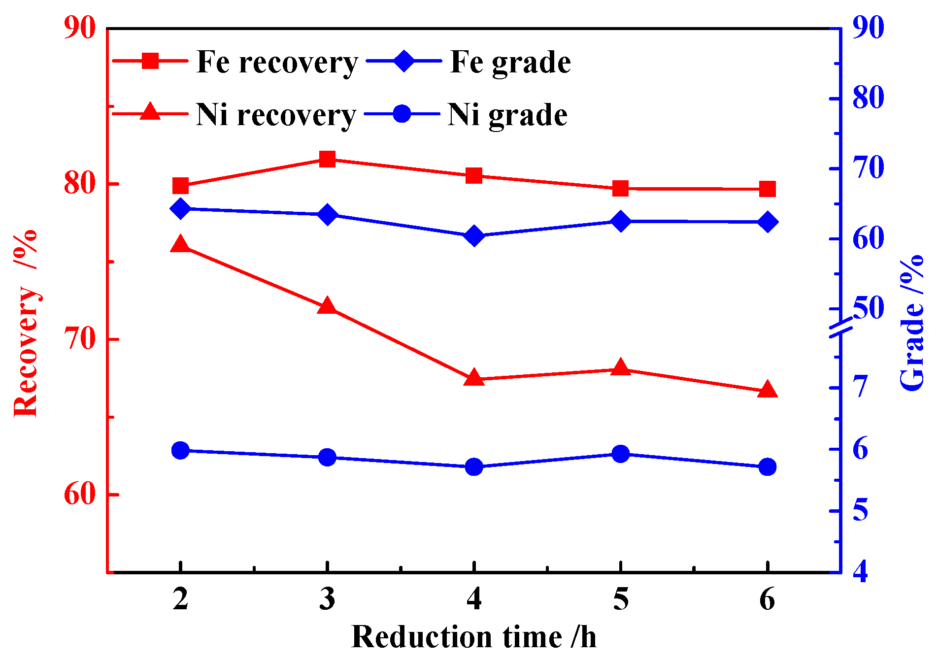
The effects of reduction time on the metallized reduction–magnetic separation of low-grade saprolitic laterite ore was shown in Figure 7. As reduction time was prolonged from 2 to 6 h, the nickel recovery decreased from 76.02% to 66.66%; the iron recovery slightly increased from 79.88% to 81.60%, and then was declined to 79.67%, with a peak of iron recovery 81.60% at 3 h; the nickel and iron grades were slightly decreased from 5.98% to 5.71% and from 64.28% to 62.42%, respectively. The nickel and iron was separated completely during metallized reduction due to the extension of reduction time so that nickel cannot be beneficiated with iron by magnetic separation. Therefore, the nickel recovery declined as a result.
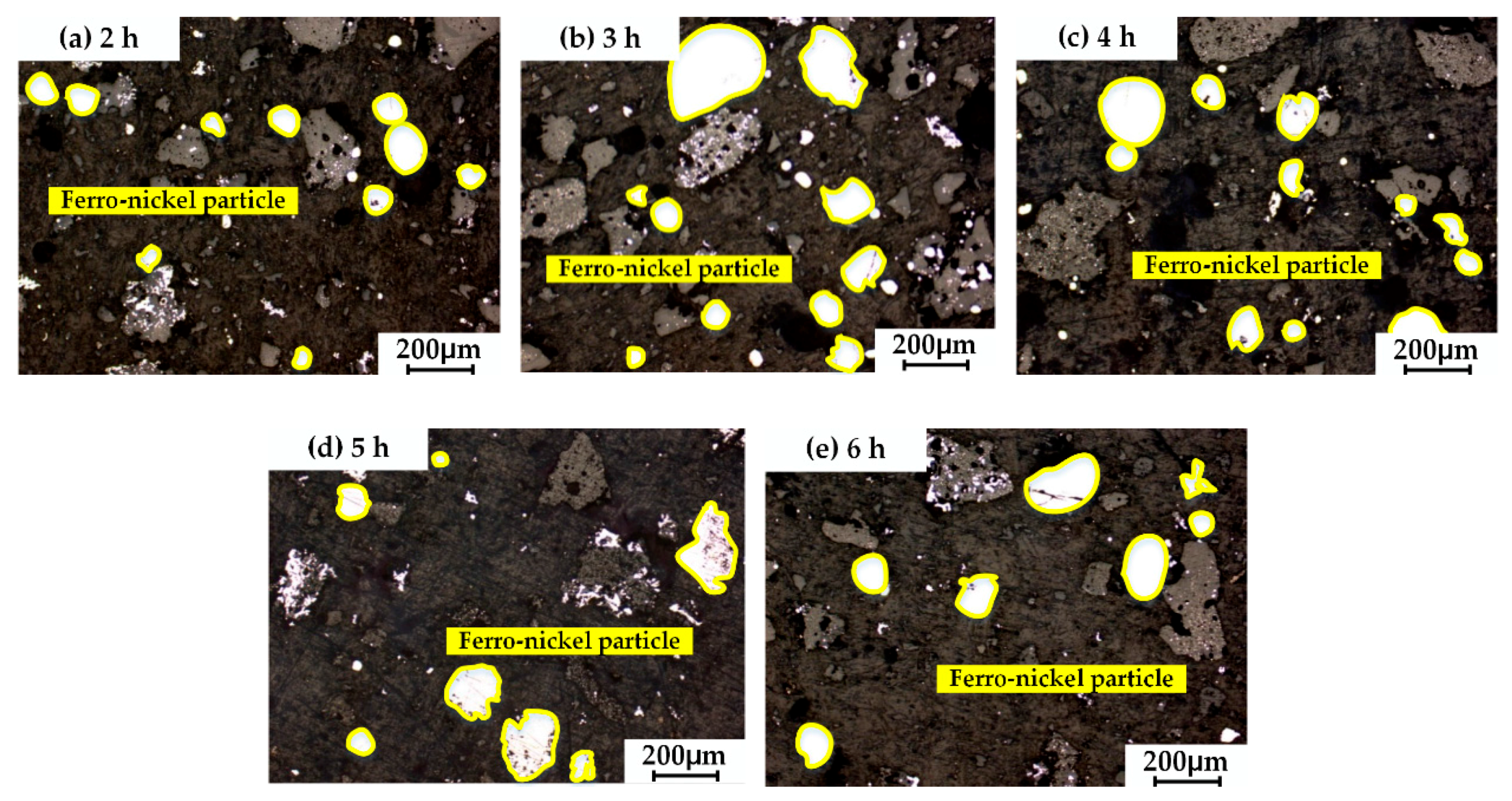
Figure 8 shows the ferro-nickel particles microstructure of reduction product under different reduction times by optical microscope. When reduction time was 2 h, ferro-nickel particles were tiny and dispersive, which is not good for magnetic separation. However, prolonging reduction time (3, 4, 5, and 6 h) made ferro-nickel particles aggregate and grow up inconspicuously. Furthermore, the lengthy reduction period promoted the aggregation of nickel without iron, causing nickel to run away from magnetic separation and the nickel recovery to decline. Therefore, the appropriate reduction time could be 2 h.
3.3. Effects of Carbon Ratio
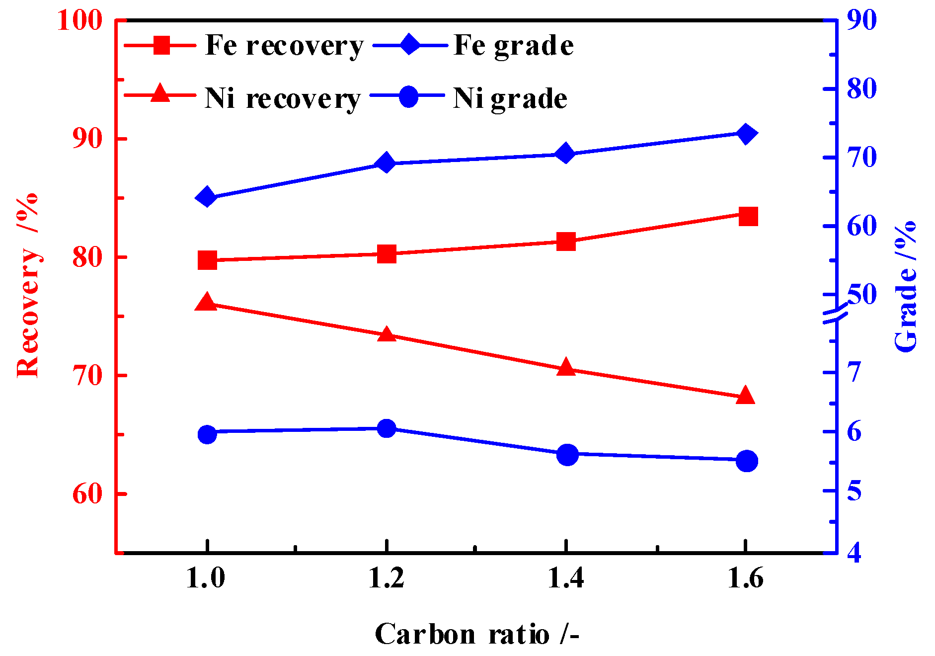
The effects of carbon ratio on the metallized reduction–magnetic separation of low-grade saprolitic laterite ore was shown in Figure 9. As the carbon ratio increased from 1.0 to 1.6, the nickel recovery declined from 76.01% to 68.20%; the iron recovery increased from 79.88% to 83.64%; the iron grade increased from 64.28% to 73.60%; the nickel grade increased from 5.98% to 6.08% and then declined to 5.54%, reaching a peak at a carbon ratio of 1.2. Increasing a little carbon ratio can facilitate reduction of iron and nickel, but excessive carbon can restrain the improvement of the nickel grade.
Figure 10 shows the ferro-nickel particles microstructure of reduction product under different carbon ratios by optical microscope. When the carbon ratio was 1.2, ferro-nickel particles aggregated bigger than at other carbon ratios. Increasing carbon ratio contributed to the reduction of iron, causing the increase of iron recovery. However, excessive carbon was bad for the aggregation and growing up of ferro-nickel particles, nickel cannot be separated with iron, the nickel recovery ratio declined as a result. Taking both nickel grade and nickel recovery into consideration, the appropriate carbon ratio is about 1.2.
3.4. Effects of CaO Addition
The effects of CaO addition on the metallized reduction–magnetic separation of low-grade saprolitic laterite ore was shown in Figure 11. When CaO addition rose from 5% to 15%, the nickel recovery increased from 74.40% to 89.36% and then declined to 81.62%, where it was the peak CaO addition 10%; the iron recovery raised initially from 90.99% to 98.23% and then fell off to 85.12%, with a peak of 98.23% at a CaO addition of 12.5%; the nickel and iron grades increased from 5.76% to 7.90% and from 61.79% to 77.32%, respectively, and then decreased to 7.16% and 69.11%, respectively, the optimal nickel and iron grades 7.90% and 77.32%, respectively, were obtained at a CaO addition of 10%.
Adding CaO can promote the reduction of nickel and iron, and can optimize dynamic condition of laterite nickel ore, which favors aggregation and the expansion of nickel and iron as well as the separation of slag and metal, thus, nickel and iron grades increased. However, when the CaO addition was over 10%, there was so much liquid phase generated due to the excess flux, resulting in the decrease of the contact area between ore and reductant. Nickel and iron particles became difficult to aggregate and grow up. More fine particles entered into the slag, increasing the difficulty of separation. Both grades and recoveries of the nickel and iron declined as a result.
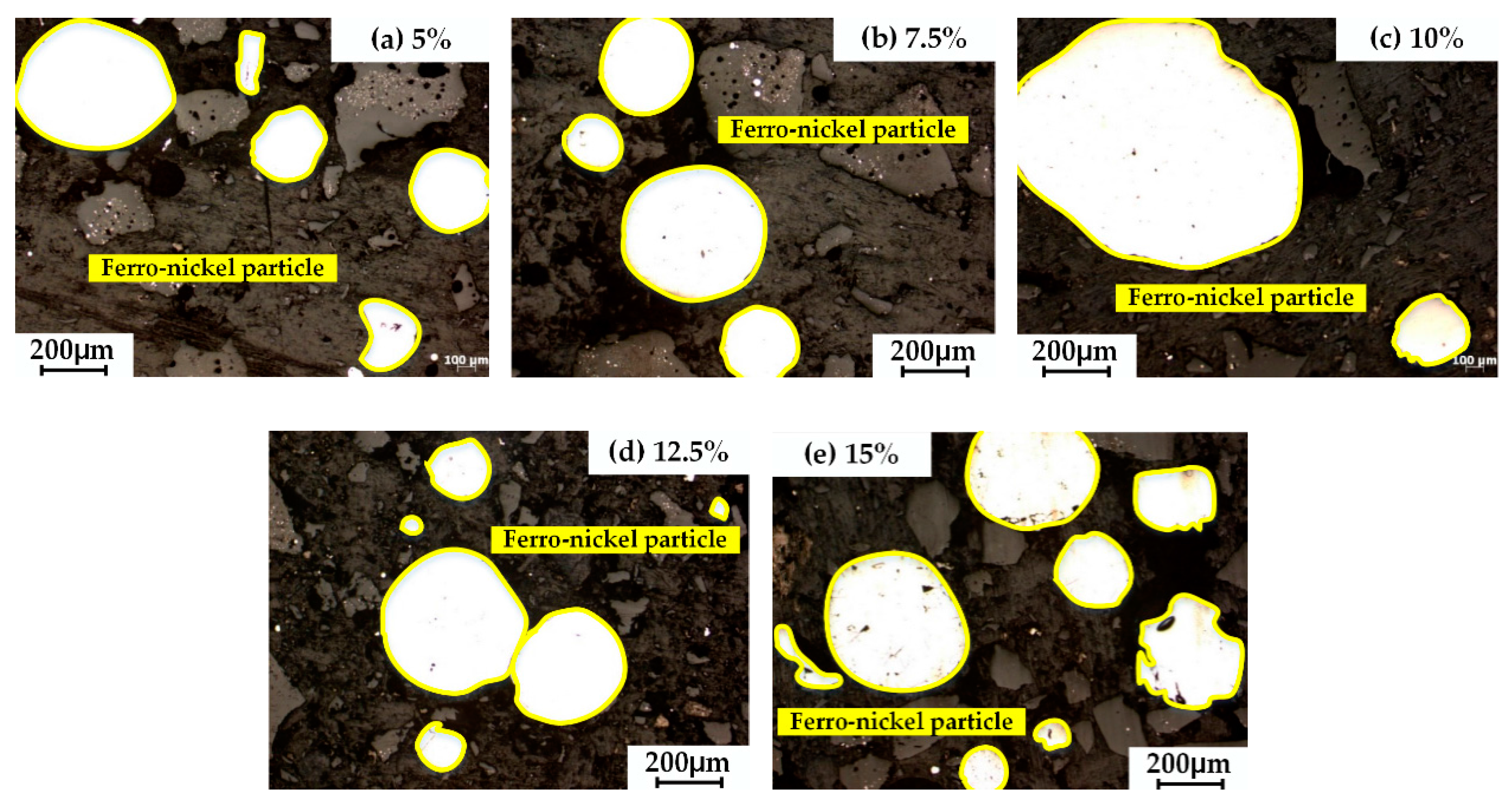
Figure 12 shows the ferro-nickel particles microstructure of the reduction product under different CaO additions by optical microscope. It is obvious that when the CaO addition was 10%, the ferro-nickel result was largest, at more than 1.0 mm in diameter. CaO greatly promoted aggregation and growing up of ferro-nickel particles. Therefore, the optimal CaO addition is 10%.
3.5. Function Mechanism of Adding CaO
According to the experimental results, appropriate CaO addition could improve nickel grade and recovery in ferro-nickel particles. Less or excess CaO addition would restrain the aggregation and growing up of ferro-nickel particles. The relative function mechanism of adding CaO may be clarified by the effects of CaO addition on the properties of slag, including its composition and its viscosity.
Figure 13 gave the melting start temperature (MT) and liquidus temperature (LT) of slag with different CaO addition ratios. The MT and LT of slag were calculated by FactSage 7.0 equilibrium module with inputting different contents of CaO, SiO2, MgO, and Al2O3 in slag. As is shown in Figure 13, with increasing CaO addition from 0 to 15%, the LT declined while the MT declined initially, then remained unchanged with a lowest temperature of 1210 °C, finally increased. The optimum condition obtained by experiment, CaO addition of 10% and reduction temperature 1350 °C, is in this range. The image indicates that the aggregation and the growing up of ferro-nickel particles happened in the mixed phase of solid and liquid. In the meantime, lower MT gave the particles sufficient time to aggregate and grow up, which resulted in the formation of large ferro-nickel particles.
The liquid generation ratios and slag viscosity were analyzed by the equilibrium module in Factsage 7.0. Figure 14 shows the variation of liquid generation ratio with different CaO additions. When the reduction temperature was 1350 °C and CaO addition was 10%, the liquid generation ratio was 95%, which is beneficial to the aggregation and growing up of the ferro-nickel particles.
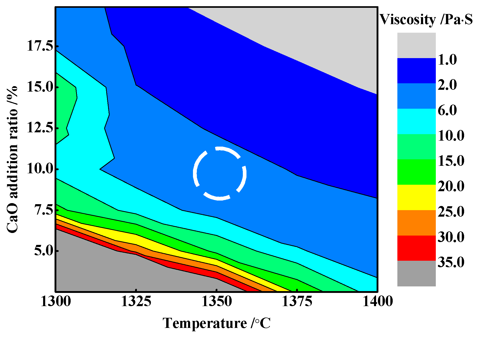
Additionally, viscosity in slag should be taken into consideration. According to the Einstein–Roscoe equation [35,36]:
where η is solid–liquid phase slag viscosity, Pa·s; η0 is liquid phase slag viscosity, Pa·s; f is solid volume fraction, a and n are constant, which are related to the size of solid particles in slag. The viscosity was calculated by a Factsage 7.0 viscosity module, as shown in Figure 15. When the reduction temperature was 1350 °C and CaO addition was 10%, the slag viscosity was 2–6 Pa·s. Therefore, the results above indicate the mechanism of adding CaO to improve nickel and iron grades and recoveries and calculate the appropriate liquid generation ratio of 95% and viscosity of the slag 2–6 Pa·s at a reduction temperature of 1350 °C, with CaO addition of 10%, providing a theoretical reference for further study.
3.6. Characterization of Magnetic Product
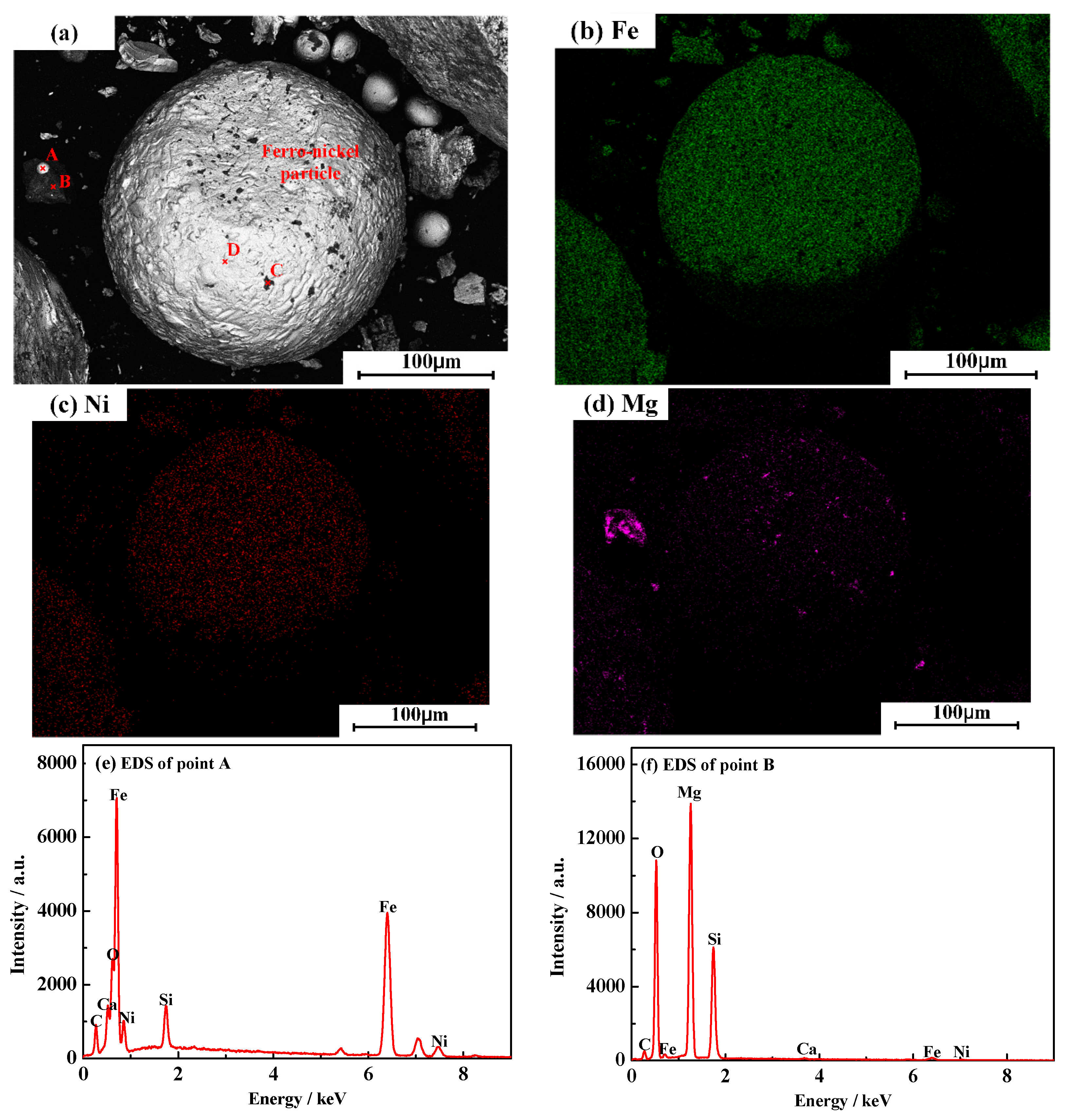
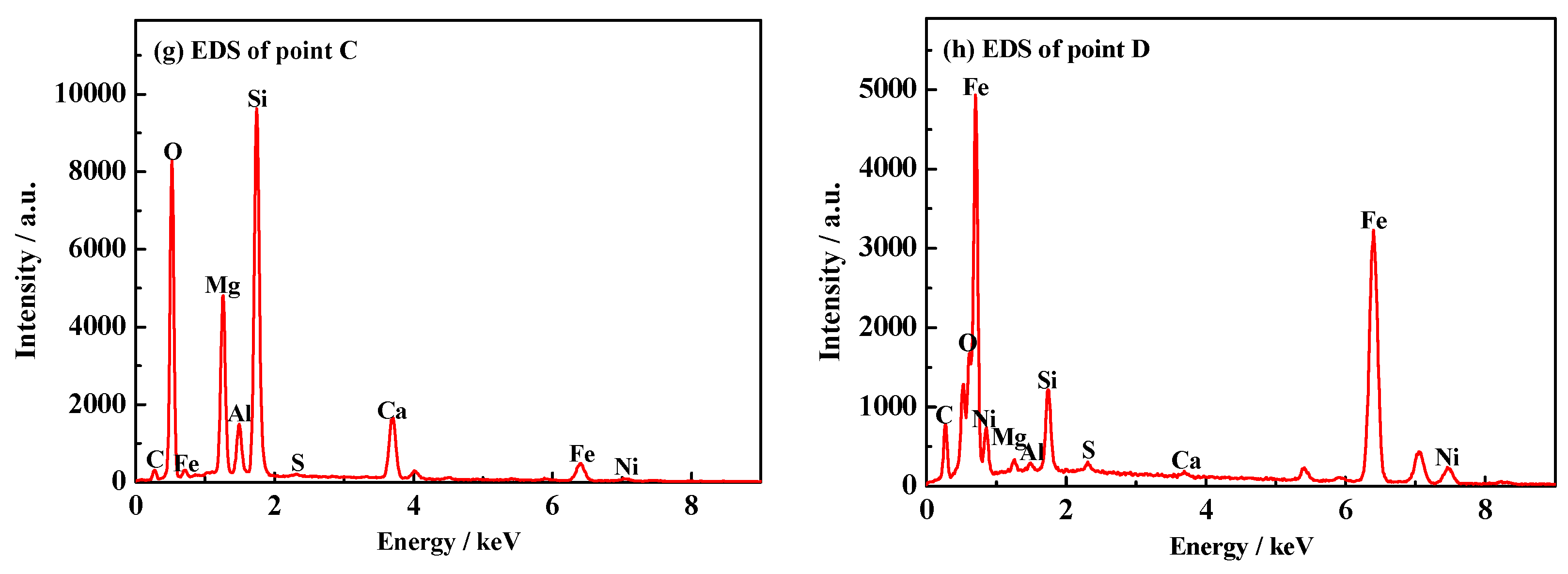
The characterization of magnetic product at the optimal condition of reduction temperature 1350 °C, reduction time 2 h, carbon ratio 1.2, and CaO addition 10% was analyzed. The chemical compositions of the magnetic product measured by chemical titration are shown in Table 4. The SEM micrographs of the magnetic product and the corresponding EDS analysis results for different points are presented in Figure 16.
As shown in Table 4, the nickel and iron grades were 7.90% and 77.32% respectively, and the corresponding nickel and iron recoveries were 95.87% and 89.36% respectively, achieving efficient recovery and utilization of iron and nickel from low-grade saprolitic laterite ore. The contents of carbon, phosphorus, and sulfur are all in reasonable ranges. Figure 16a–h shows the SEM image and EDS spectra of magnetic product particles. The nickel and iron in magnetic product basically existed in alloy state. The ferro-nickel particles were formed by the aggregation and growing up of metallic iron and nickel (Figure 16a (point D) and 16h) and a small amount of gangue embedded in the ferro-nickel alloy particle (Figure 16a (point C) and 16g). In addition, a small amount of ferro-nickel alloy (Figure 16a (point A) and 16e) was embedded in the gangue (Figure 16a (point B) and 16f) by magnetic separation.
4. Conclusions
- (1)
- The ferro-nickel alloy was prepared successfully from low-grade saprolitic laterite ore using a process of metallized reduction–magnetic separation.
- (2)
- The results indicated that, under the optimal process parameters of reduction temperature 1350 °C, reduction time 2 h, carbon ratio 1.2, and CaO addition ratio 10%, the nickel and iron grades in the magnetic product were 7.90% and 77.32%, respectively. Meanwhile, the nickel and iron recoveries were 89.36% and 95.87%, which reached high efficiency recovery of nickel and iron.
- (3)
- The appropriate amount of CaO contributed to liquid generation and slag viscosity. The conditions with a liquid generation ratio of 95% and a viscosity of slag 2–6 Pa·s at a reduction temperature of 1350 °C and CaO addition of 10% could favor the aggregation and growing up of ferro-nickel particles and improve recoveries of nickel and iron.
Acknowledgments
The authors are especially thankful to the National Natural Science Foundation of China (51374058), the China Postdoctoral Science Foundation (2016M601321), and the Fundamental Research Funds of the Central Universities of China (N162503003)
Author Contributions
Zhenggen Liu and Zhihao Wang conceived and designed the experiments; Zhihao Wang performed the experiments and wrote the paper; Mansheng Chu contributed materials and analysis tools; Hongtao Wang, Wei Zhao, and Lihua Gao analyzed the data.
Conflicts of Interest
The authors declare no conflict of interest.
References
- Zheng, G.L.; Zhu, D.Q.; Pan, J.; Li, Q.H. Pilot scale test of producing nickel concentrate from low-grade saprolitic laterite by direct reduction-magnetic separation. J. Cent. South Univ. 2014, 21, 1771–1777. [Google Scholar] [CrossRef]
- Yan, L.Y.; Wang, A.J. Analysis of global nickel supply and demand patterns. China Min. Mag. 2016, 25, 1–5. [Google Scholar]
- Li, J.H.; Li, Y.Y.; Zheng, S. Research review of laterite nickel ore metallurgy. Nonferrous Met. Sci. Eng. 2015, 6, 35–40. [Google Scholar]
- Yu, L. Development situation of Russian sulfide nickel ore resources. World Nonferrous Met. 2013, 3, 60–62. [Google Scholar]
- Yang, Z.Q.; Wang, Y.Q.; Gao, Q. Present situation and development strategy and key technologies of China’s nickel resources sustainable development. Conserv. Util. Miner. Res. 2016, 2, 58–69. [Google Scholar]
- Bai, X.Y. Exploitation and utilization situation and input strategy of nickel ore resources in China. China Trade 2014, 6, 123–125. [Google Scholar]
- Santos, R.M.; Audenaerde, A.V.; Chiang, Y.W.; Iacobescu, R.I.; Knops, P.; Gerven, T.V. Nickel extraction from olivine: Effect of carbonation pre-treatment. Metals 2015, 5, 1620–1644. [Google Scholar] [CrossRef] [Green Version]
- Dalvi, A.D.; Bacon, W.G.; Osborne, R.C. The past and the future of nickel laterites. In Proceedings of the PDAC 2005 International Convention, Toronto, ON, Canada, 6–9 March 2005. [Google Scholar]
- Charles, G. Mineral Commodity Summaries; U.S. Geological Survey: Washington, DC, USA, 2003.
- Rhamdhani, M.A.; Hayes, P.C.; Jak, E. Nickel laterite Part 1—Microstructure and phase characterizations during reduction roasting and leaching. Miner. Process. Extr. Metall. 2009, 3, 129–145. [Google Scholar] [CrossRef]
- Norgate, T.; Jahanshahi, S. Assessing the energy and greenhouse gas footprints of nickel laterite processing. Miner. Eng. 2011, 7, 698–707. [Google Scholar] [CrossRef]
- Cao, Z.C.; Sun, T.C.; Yang, H.F. Recovery of iron and nickel from nickel laterite ore by direct reduction roasting and magnetic separation. J. Univ. Sci. Technol. Beijing 2010, 6, 708–712. [Google Scholar]
- Shi, Q.X.; Qiu, G.X.; Wang, X.M. Study on direct reduction and enrichment of nickel from laterite-nickel ore. Gold 2009, 11, 46–49. [Google Scholar]
- Liang, W.; Wang, H.; Fu, J.G. High recovery of ferro-nickel from low grade nickel laterite ore. J. Cent. South Univ. Sci. Technol. 2011, 8, 2173–2177. [Google Scholar]
- Li, G.H.; Rao, M.J.; Jiang, T. Innovative process for preparing ferronickel materials from laterite ore by reduction roasting-magnetic separation. Chin. J. Nonferrous Met. 2011, 12, 3137–3142. [Google Scholar]
- Wang, C.Y. Chloridizing segregation of Yuanjiang lean nickel oxide ore. Min. Metall. 1997, 3, 55–59. [Google Scholar]
- Goodall, G. Nickel Recovery from Reject Laterite. Ph.D. Thesis, Mc Gill University, Montreal, QC, Canada, 2007. [Google Scholar]
- Warner, A.E.; Diaz, C.M.; Dalvi, A.D.; Mackey, P.J.; Tarasov, A.V. JOM world nonferrous smelter survey, part III: Nickel: Laterite. J. Min. Met. Mater. Soc. 2006, 58, 11–20. [Google Scholar] [CrossRef]
- Ishii, K. Development of ferro-nickel smelting from laterite in Japan. Int. J. Min. Process. 1987, 19, 15–24. [Google Scholar] [CrossRef]
- King, M.G.; Grund, G.; Schonewille, R. A mid-term report on Falconbridge’s 15 year technology plan for nickel. In Proceedings of the European Metallurgical Conference (EMC 2005), Dresden, Germany, 18–21 September 2005; Volume 3, pp. 935–954. [Google Scholar]
- Ahmed, H.M.; Viswanathan, N.; Bjorkman, B. Composite pellets—A potential raw material for iron-making. Steel Res. Int. 2014, 85, 293–306. [Google Scholar] [CrossRef]
- Yu, W.; Sun, T.C.; Liu, Z.Z.; Kou, J.; Xu, C.Y. Study on the strength of cold-bonded high-phosphorus oolitic hematite-coal composite briquettes. Int. J. Miner. Metall. Mater. 2014, 5, 423–430. [Google Scholar] [CrossRef]
- Zhang, H.Q.; Zhu, D.Q. New technology of coal-based direct reduction for unfired pellet and its application. Res. Iron Steel 2003, 1, 58–62. [Google Scholar]
- Kasai, A.; Matsui, Y.; Noma, F. Cold strength enhancement mechanism of carbon composite iron ore hot briquet. Iron Steel 2009, 87, 313–319. [Google Scholar] [CrossRef]
- Chu, M.; Nogami, H.; Jun, I.Y. Numerical analysis on blast furnace performance under operation with top gas recycling and carbon composite agglomerates charging. ISIJ Int. 2004, 12, 2159–2167. [Google Scholar] [CrossRef]
- Chen, S.Y.; Chu, M.S. Metalizing reduction and magnetic separation of vanadium titano-magnetite based on hot briquetting. Int. J. Miner. Metall. Mater. 2014, 3, 225–233. [Google Scholar] [CrossRef]
- Chu, M.S.; Liu, Z.G.; Wang, Z.C. Fundamental study on carbon composite iron ore hot briquette used as blast furnace burden. Steel Res. Int. 2011, 5, 521–528. [Google Scholar]
- Matsui, Y.; Sawayama, M.; Kasai, A. Reduction behavior of carbon composite iron ore hot briquette in shaft furnace and scope on blast furnace performance reinforcement. ISIJ Int. 2007, 12, 1904–1912. [Google Scholar] [CrossRef]
- Tanaka, Y.; Ueno, T.; Okumura, K. Reaction behavior of coal rich composite iron ore hot briquettes under load at high temperatures until 1400.DEG.C. ISIJ Int. 2011, 8, 1240–1246. [Google Scholar] [CrossRef]
- Suzuki, H.; Mizoguchi, H.; Hayashi, S. Influence of ore reducibility on reaction behavior of ore bed mixed with coal composite iron ore hot briquettes. ISIJ Int. 2011, 8, 1255–1261. [Google Scholar] [CrossRef]
- Long, H.M.; Chun, T.J.; Di, Z.X.; Wang, P.; Meng, Q.M.; Li, J.X. Preparation of metallic iron powder from pyrite cinder by carbothermic reduction and magnetic separation. Metals 2016, 6, 88. [Google Scholar] [CrossRef]
- Fang, J.; Wang, X.J.; Shi, T. Technology and Theory of Non-Blast Furnace Ironmaking; Metallurgical Industry Press: Beijing, China, 2010; p. 1. [Google Scholar]
- Li, M.; Peng, B.; Chai, L.Y.; Peng, N.; Yan, H.; Hou, D.K. Recovery of iron from zinc leaching residue by selective reduction roasting with carbon. J. Hazard. Mater. 2012, 237, 323–330. [Google Scholar] [CrossRef] [PubMed]
- Satoh, K.; Noguchi, T.; Hino, M. Reduction and carburization of iron oxide by carbonaceous materials. Steel Res. Int. 2010, 81, 834–840. [Google Scholar] [CrossRef]
- Einstein, A. Eine neue bestimmung der moleküldimensionen. Ann. Phys. 1906, 324, 289–306. [Google Scholar] [CrossRef]
- Roscoe, R. The viscosity of suspensions of rigid spheres. Br. J. Appl. Phys. 1952, 8, 267–269. [Google Scholar] [CrossRef]
Figure 1.
X-Ray Diffraction (XRD) analysis of laterite nickel ore.
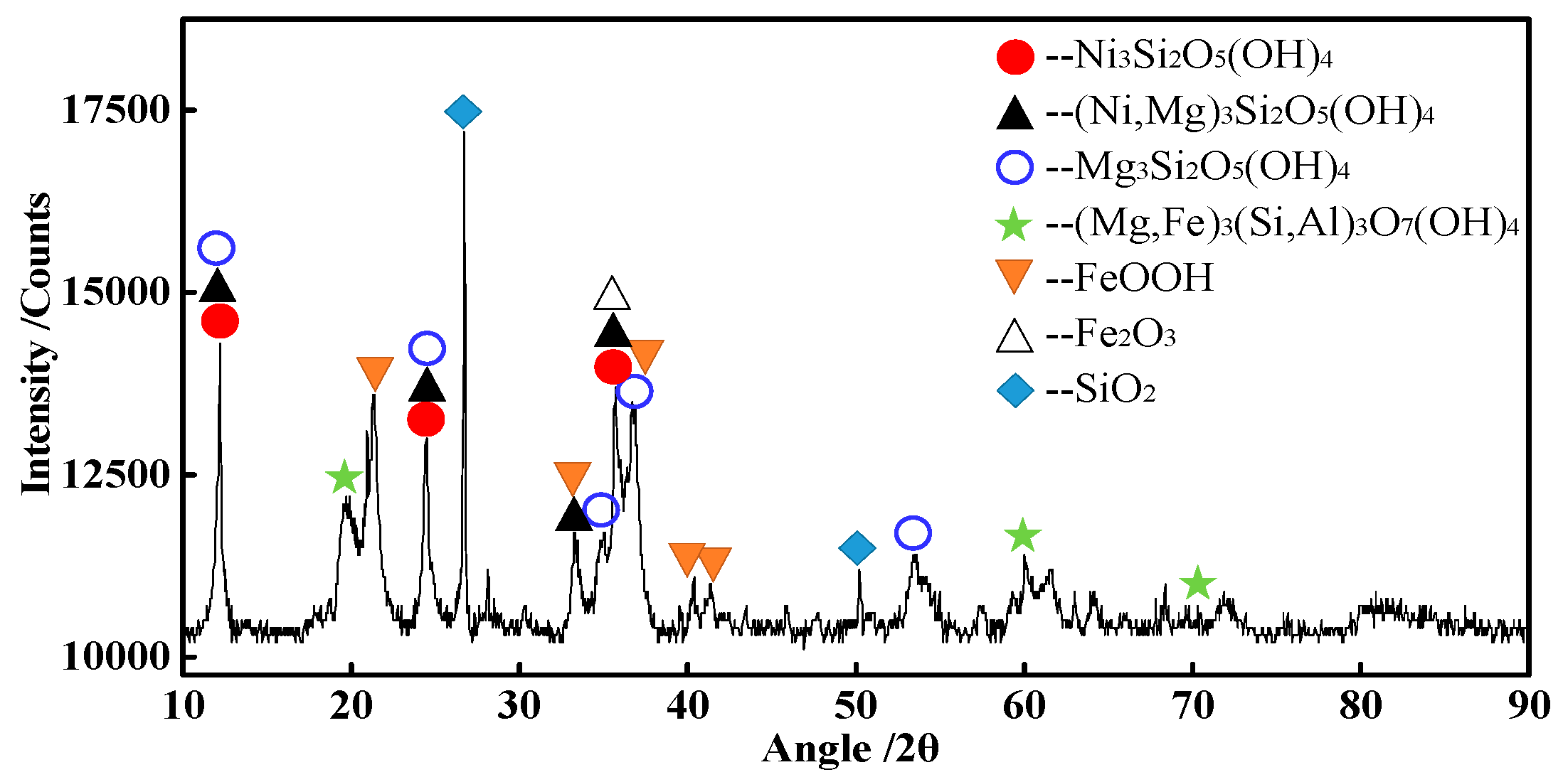
Figure 2.
Process diagram of metallized reduction–magnetic separation.
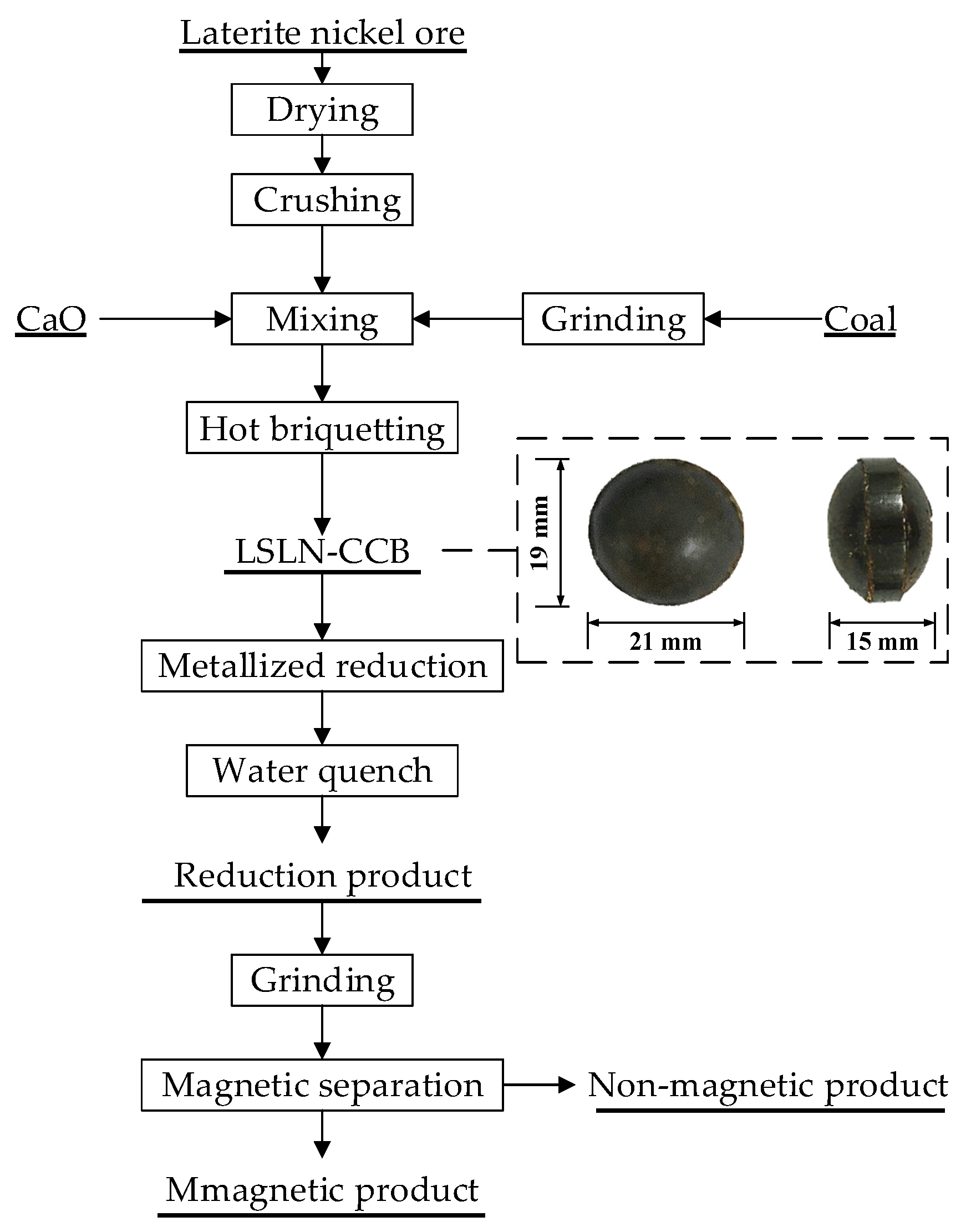
Figure 3.
Schematic diagram of tube furnace system for low-grade saprolitic laterite nickel ore carbon composite hot briquette (LSLN-CCB) reduction.
Figure 3.
Schematic diagram of tube furnace system for low-grade saprolitic laterite nickel ore carbon composite hot briquette (LSLN-CCB) reduction.
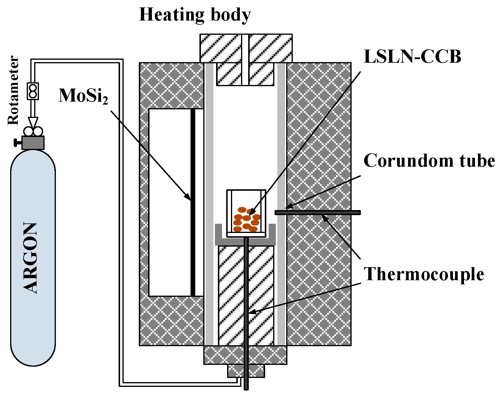
Figure 4.
Correlation between standard Gibbs free energy and temperature for Equations (1)–(9).
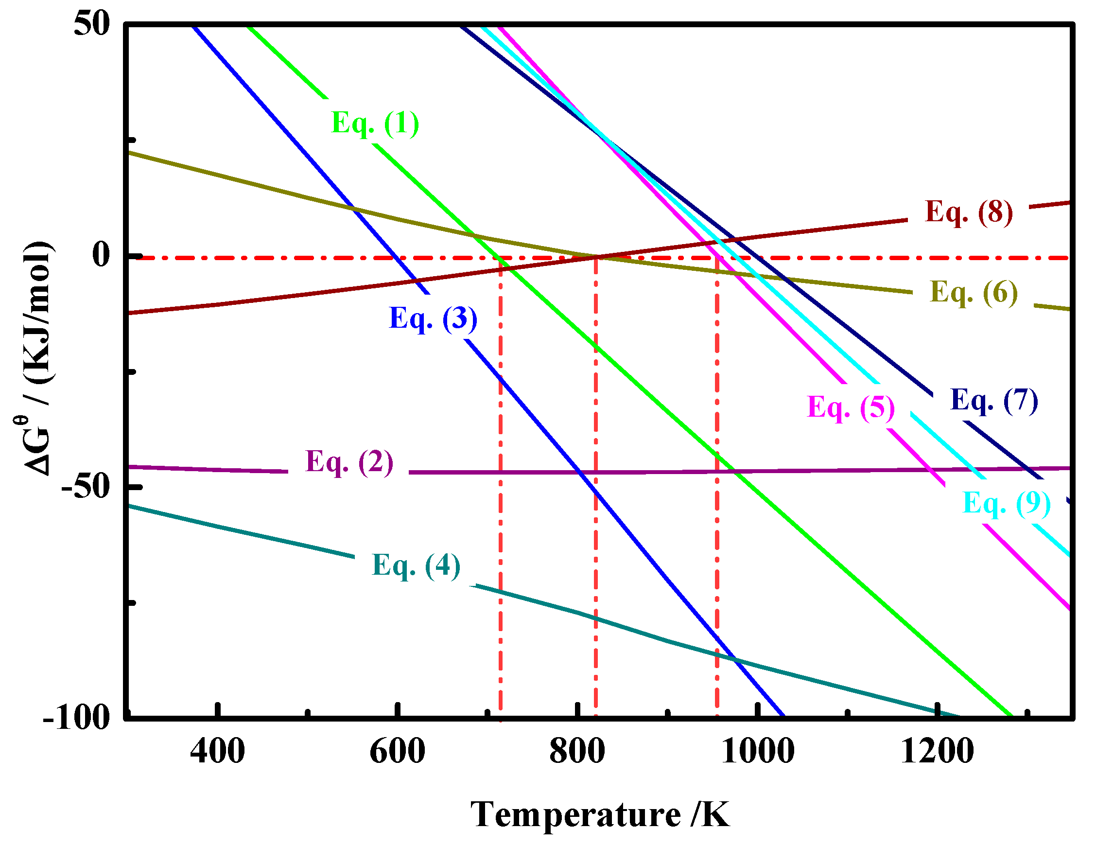
Figure 5.
Effects of reduction temperature on grades and recoveries of Ni and Fe.
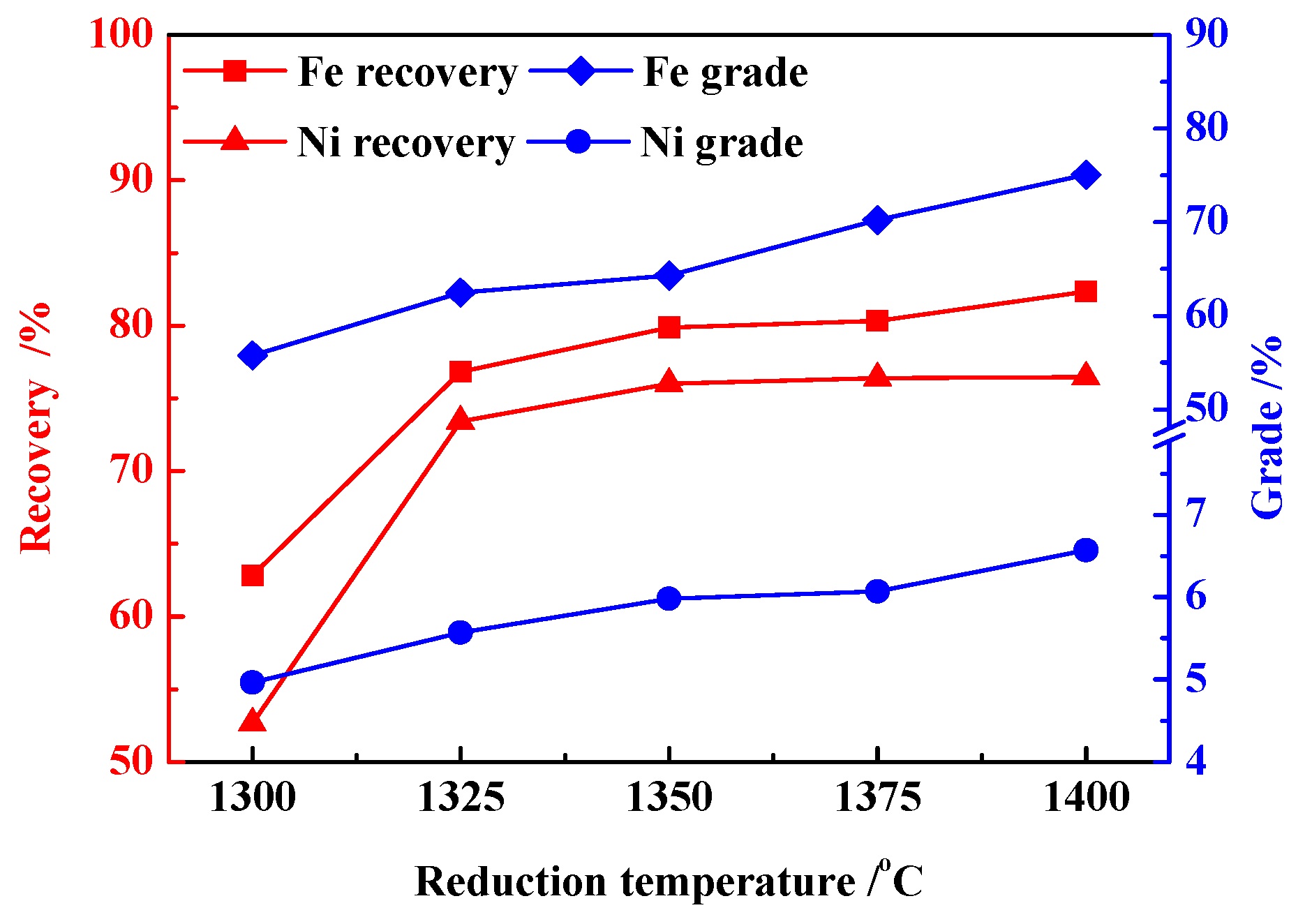
Figure 6.
Optical microscope images of ferro-nickel particles under different reduction temperatures: (a) 1300 °C; (b) 1325 °C; (c) 1350 °C; (d) 1375 °C; (e) 1400 °C.
Figure 6.
Optical microscope images of ferro-nickel particles under different reduction temperatures: (a) 1300 °C; (b) 1325 °C; (c) 1350 °C; (d) 1375 °C; (e) 1400 °C.

Figure 7.
Effects of reduction time on grades and recoveries of Ni and Fe.

Figure 8.
Optical microscope images of ferro-nickel particles under different reduction times: (a) 2 h; (b) 3 h; (c) 4 h; (d) 5 h; (e) 6 h.
Figure 8.
Optical microscope images of ferro-nickel particles under different reduction times: (a) 2 h; (b) 3 h; (c) 4 h; (d) 5 h; (e) 6 h.

Figure 9.
Effects of carbon ratio on grades and recoveries of Ni and Fe.

Figure 10.
Optical microscope images of ferro-nickel particles under different carbon ratios: (a) 1.0; (b) 1.2; (c) 1.4; (d) 1.6.
Figure 10.
Optical microscope images of ferro-nickel particles under different carbon ratios: (a) 1.0; (b) 1.2; (c) 1.4; (d) 1.6.
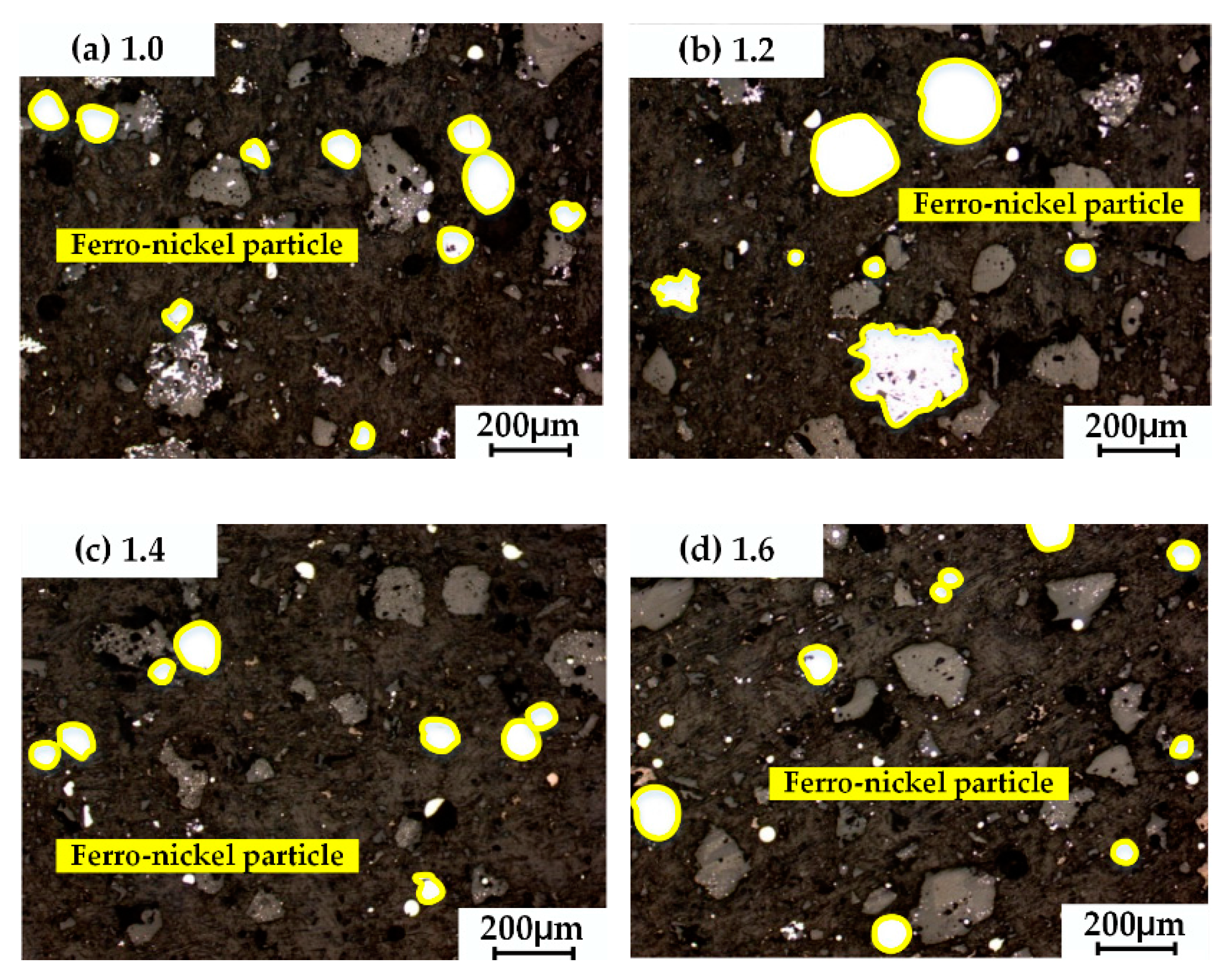
Figure 11.
Effects of CaO addition on grades and recoveries of Ni and Fe.
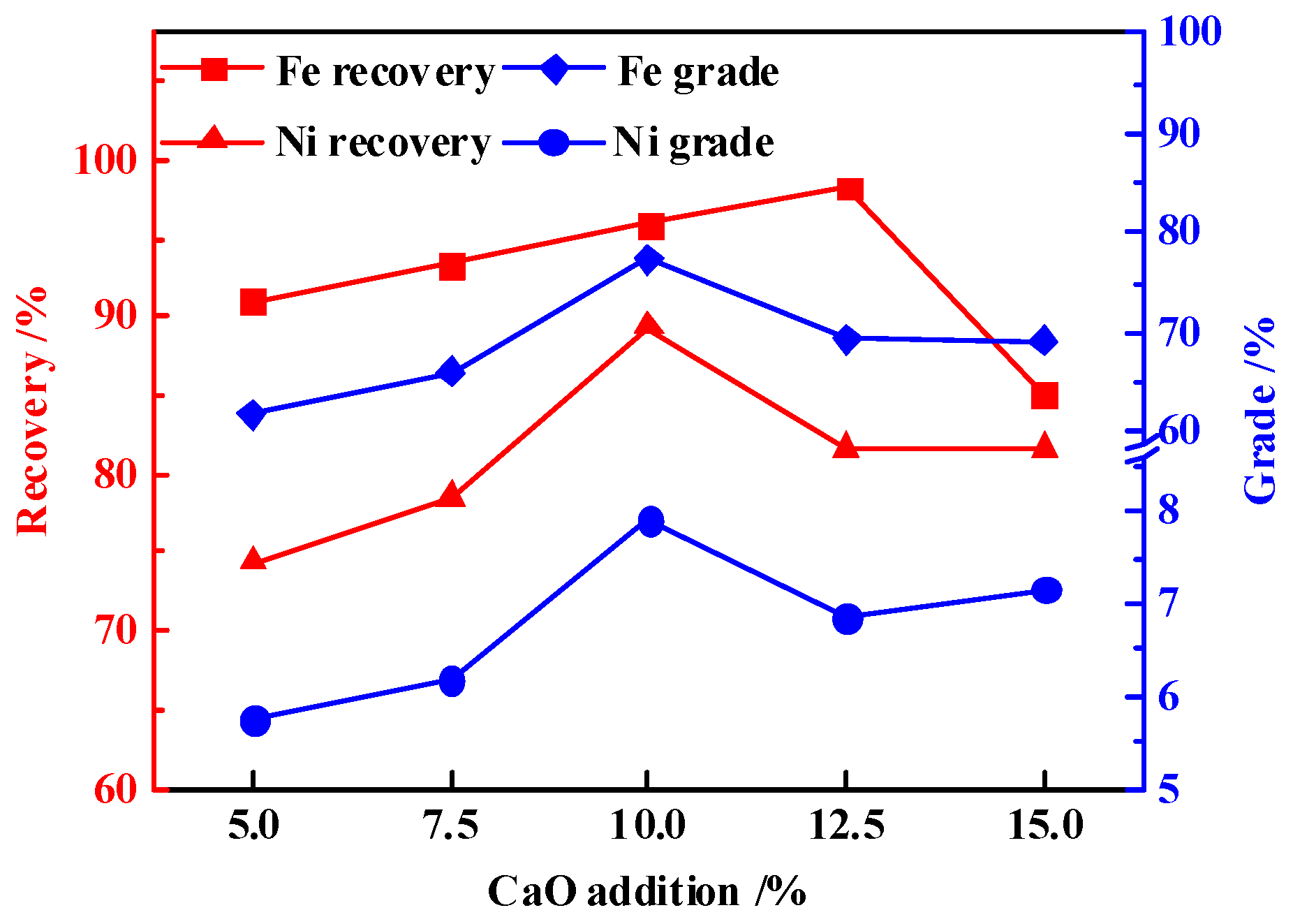
Figure 12.
Optical microscope images of ferro-nickel particles under different CaO additions: (a) 5%; (b) 7.5%; (c) 10%; (d) 12.5%; (e) 15%.
Figure 12.
Optical microscope images of ferro-nickel particles under different CaO additions: (a) 5%; (b) 7.5%; (c) 10%; (d) 12.5%; (e) 15%.

Figure 13.
Melting start temperature and liquidus temperature with different CaO addition ratios.
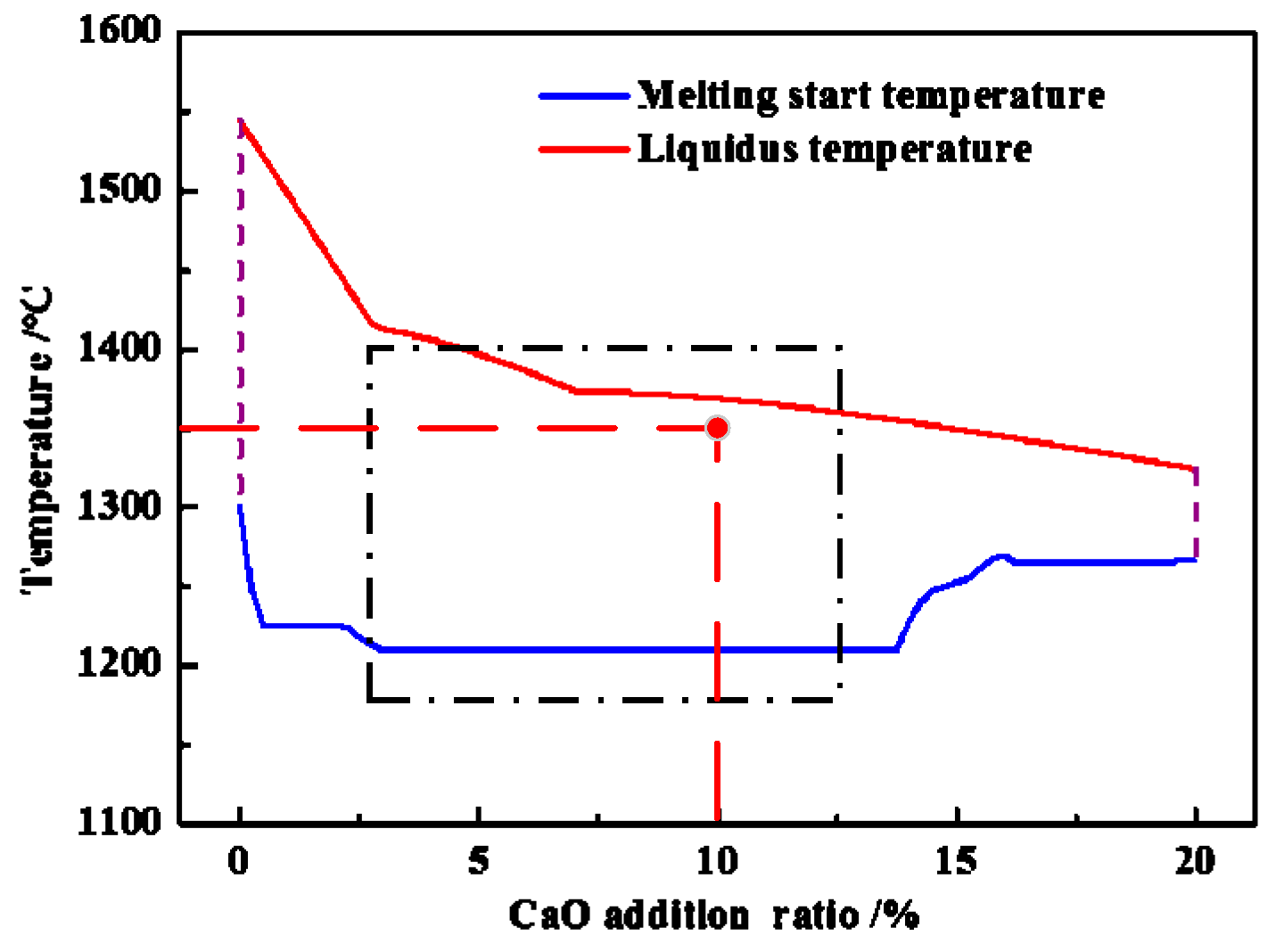
Figure 14.
Variation of liquid generation ratio for different CaO additions.
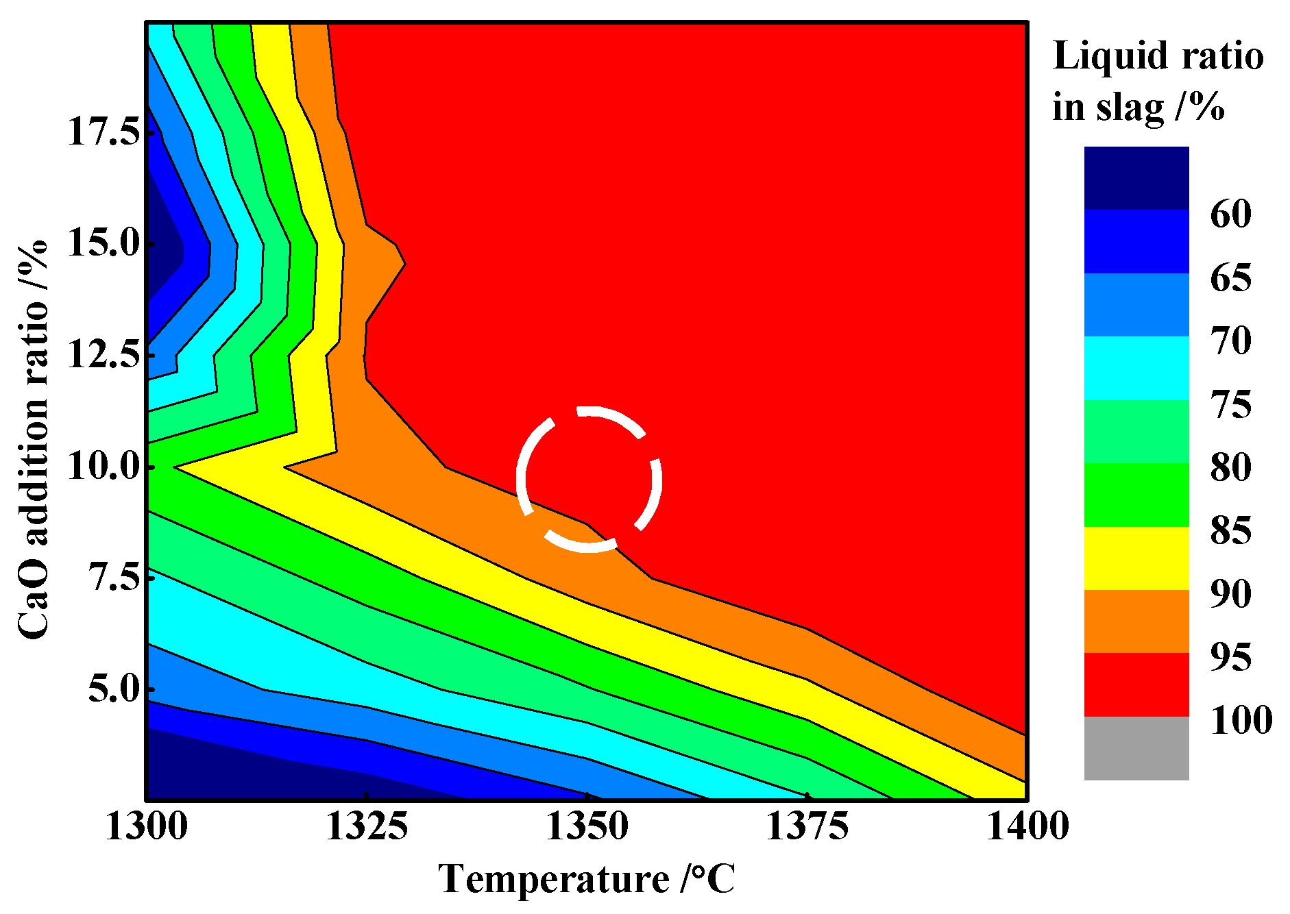
Figure 15.
Effect on slag system viscosity by CaO addition.

Figure 16.
SEM image and EDS spectra of magnetic product particles.


Table 1.
Chemical composition of the laterite nickel ore (wt %).
| Element | TFe | FeO | Ni | CaO | SiO2 | MgO | Al2O3 | Cr2O3 | P | S |
|---|---|---|---|---|---|---|---|---|---|---|
| Content | 19.57 | 0.21 | 1.82 | 0.09 | 34.78 | 12.98 | 4.00 | 1.40 | 0.003 | 0.028 |
Table 2.
Industrial composition of the coal (wt %).
| Item | Fixed Carbon | Ash | Volatile | Total Sulfur | Moisture | Ash | |||
|---|---|---|---|---|---|---|---|---|---|
| CaO | SiO2 | MgO | Al2O3 | ||||||
| Content | 60.86 | 8.19 | 30.45 | 0.14 | 0.5 | 2.95 | 51.91 | 1.08 | 29.97 |
Table 3.
Details of the experimental parameters.
| Item | Parameter | ||||
|---|---|---|---|---|---|
| Reduction temperature (°C) | 1300 | 1325 | 1350 | 1375 | 1400 |
| Redution time (h) | 2 | 3 | 4 | 5 | 6 |
| Carbon ratio | 1.0 | 1.2 | 1.4 | 1.6 | - |
| CaO addition (%) | 5 | 7.5 | 10 | 12.5 | 15 |
Table 4.
The chemical compositions of the magnetic product (wt %).
| Element | TFe | Ni | C | P | S |
|---|---|---|---|---|---|
| Content | 77.32 | 7.90 | 2.50 | 0.002 | 0.056 |
© 2017 by the authors. Licensee MDPI, Basel, Switzerland. This article is an open access article distributed under the terms and conditions of the Creative Commons Attribution (CC BY) license (http://creativecommons.org/licenses/by/4.0/).
Share and Cite
MDPI and ACS Style
Wang, Z.; Chu, M.; Liu, Z.; Wang, H.; Zhao, W.; Gao, L. Preparing Ferro-Nickel Alloy from Low-Grade Laterite Nickel Ore Based on Metallized Reduction–Magnetic Separation. Metals 2017, 7, 313. https://doi.org/10.3390/met7080313
AMA Style
Wang Z, Chu M, Liu Z, Wang H, Zhao W, Gao L. Preparing Ferro-Nickel Alloy from Low-Grade Laterite Nickel Ore Based on Metallized Reduction–Magnetic Separation. Metals. 2017; 7(8):313. https://doi.org/10.3390/met7080313
Chicago/Turabian StyleWang, Zhihao, Mansheng Chu, Zhenggen Liu, Hongtao Wang, Wei Zhao, and Lihua Gao. 2017. "Preparing Ferro-Nickel Alloy from Low-Grade Laterite Nickel Ore Based on Metallized Reduction–Magnetic Separation" Metals 7, no. 8: 313. https://doi.org/10.3390/met7080313
Note that from the first issue of 2016, this journal uses article numbers instead of page numbers. See further details here.