Effect of Welding Process on Microstructural and Mechanical Characteristics of Hardox 600 Steel


Department of Materials Science, Welding and Strength of Materials, Wroclaw University of Technology, Smoluchowskiego Street 25, 50-370 Wrocław, Poland
*
Author to whom correspondence should be addressed.
Metals 2017, 7(9), 349; https://doi.org/10.3390/met7090349
Submission received: 17 July 2017
/
Revised: 29 August 2017
/
Accepted: 31 August 2017
/
Published: 5 September 2017
Abstract
:In the article, the structure and selected mechanical properties of welded Hardox 600 steel are presented. It is shown that, after welding of this material in as-delivered condition (i.e., with post-martensitic structure), structures of lower wear resistance are created within heat-affected zones. These zones are over 80 mm wide, which makes them susceptible to uneven and fast wear in their intended applications. On the grounds of microscopic tests and hardness measurements, a thermal treatment of welded joints is suggested, consisting of quenching and low-temperature tempering of heat-affected zones. As a result of this treatment, the material structure in these areas becomes similar to the base material structure. Under laboratory conditions, the performed heat treatment does not cause any incompatibilities (cracks) in the welds.
1. Introduction
Relying on their highly usable properties, metallic materials still make a basic constructional material used for selected assemblies and machine parts. This is dictated by their universality of application, susceptibility to machining, declared satisfactory weldability and high mechanical properties, as well as favourable costs of manufacture. During the last two decades, the materials called by their manufacturers as low-alloy abrasive-wear resistant martensitic steels became very popular [1,2,3,4,5,6,7,8,9]. A characteristic feature of these steels, besides their declared high abrasive-wear resistance, are very high mechanical properties reached by their uniform structure on the entire cross-section of the sheet material. These properties are obtained thanks to a strictly-selected chemical composition depending on sheet thickness, especially to microadditions of boron and a reduced concentration of phosphorus and sulphur, as well as by thermal or thermo-mechanical treatment. Generally, these steels are mostly characterised by microaddition of boron ranging between 0.002 and 0.005 wt %. Within this range, boron dissolves in austenite, making it possible, even at normal volumetric hardening, to obtain uniform martensitic or bainitic structures on the entire cross-section of the part. It is worth emphasising that the currently-manufactured steels of this group are characterised by very high indices of static strength reaching 2000 MPa, with maintained plasticity and impact strength. It is also important that these parameters are obtained even for low or medium (up to ca. 0.45%) concentrations of carbon, which is the basic argument for these steels, especially in welding technologies. In Table 1 and Table 2, selected properties of (popular) low-alloy high-strength steels, declared by their manufacturers, are compared.
As results from literature data [16,17,18,19], confirmed also by our own results [20,21,22,23,24,25] concerning the popular abrasive-wear resistant steels Hardox 400 and Hardox 500, these materials are characterised by good weldability and give relatively high mechanical properties of welded joints. However, thermal processes accompanying welding result in degradation of microstructures in heat-affected zones. This results in significant changes of hardness and local loss of abrasive-wear resistance. These phenomena are connected not only with welding, but also with processing and forming operations of constructional elements made of these materials. It is postulated by Oskwarek in [26] that unfavourable structures and hardness levels occurring in welded joints of low-alloy high-strength steels can be changed by additional heat treatment. As regards martensitic and toughened steels, the following remarks are stated by Tasak and Pilarczyk in the works [27,28]:
- −
- The problem of “unhardened layer” (“soft layer”) occurs in heat-affected zone, deciding strength of the entire structure;
- −
- The changes occurring in heat-affected zones of welded joints of steels that were, before welding, hardened or hardened and low-tempered only, lead to the creation of zones with lowered hardness and tensile strength resulting from tempering processes in the temperature range between 250 °C and AC1 (according to Fe-Fe3C diagram);
- −
- By proper selection of chemical composition of additional materials and optimum selection of welding conditions and parameters, structures and mechanical properties close to those of the base material can be obtained in HAZ with no additional operations;
- −
- Application of limited welding energy makes it possible to obtain narrow degraded zone (“soft layer”) which does not result in lower mechanical properties of the weld.
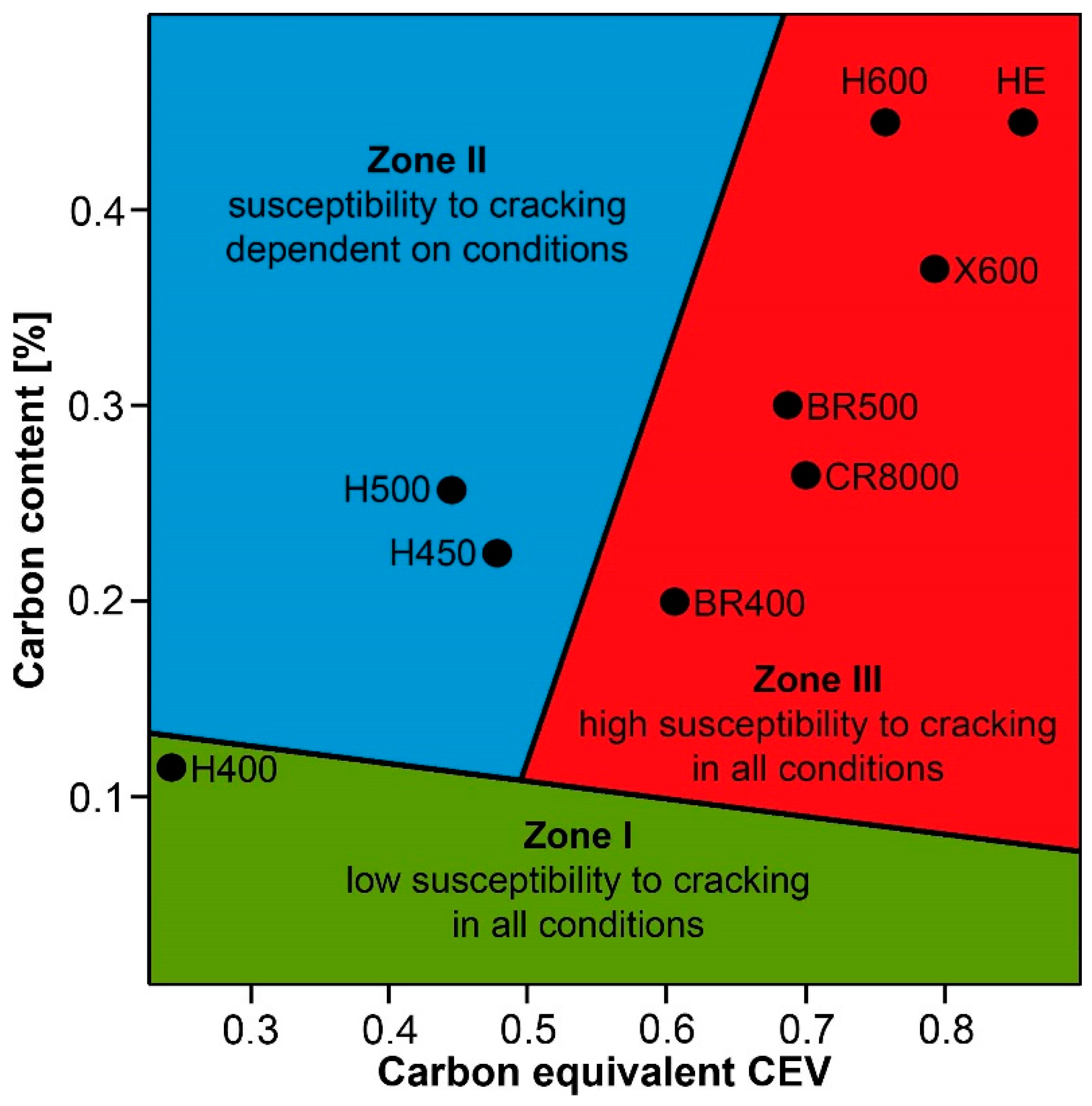
In connection with the above, the authors of this paper have decided that, from a practical point of view, it is worth complementing the issues related to making and optimizing the properties of welded joints of Hardox 600 steel. This is additionally motivated by the adverse opinion about the weldability of this steel, which generally results in resignation of its welding or in replacing it by another grade with lower strength, but declared better weldability. On the grounds of the results of numerous own research works related to chemical and structural properties of low-alloy martensitic steels [29,30,31,32,33,34,35,36,37], it can be generally stated that Hardox steels (mostly 400, 450, and 500 grades) show good weldability, as additionally confirmed by their position in the C-CEV diagram (Figure 1) in the area of low (I) or dependent on welding conditions (II) susceptibility to cracking. However, higher grades of this steel (e.g., Extreme) and the analysed Hardox 600 do not seem to confirm this statement (see Table 3 and Figure 1). This conclusion is also confirmed by the information coming from manufacturers of these steels, clearly indicating that, in practice, they cannot be joined by welding. The most often indicated problems with weldability of the steels Hardox 600 and Hardox Extreme are susceptibility to brittle cracking of the welded joints and wide zones of lower hardness in comparison to the base material.
On the grounds of the abovementioned information, the following goals of the presented research works can be defined:
- −
- Identification of macro- and microscopic structures of welded joints of Hardox 600 in as-delivered condition with determination of the extent of structural changes within the entire joint; and
- −
- Producing, by heat treatment, structural changes of the joint in order to eliminate or to minimise the changes caused by welding.
2. Material and Methodology
Welded joints of Hardox 600 were made by TIG (tungsten inert gas) with the use of ESAB CADDY TIG 2200iw welder (ESAB, Katowice, Poland) and welding materials and parameters recommended by the manufacturer. Selected properties of the used welding materials are given in Table 4. The selection of the welding materials takes into account, i.e., their hardenability, susceptibility to cracking and to create a proper structure, and mechanical properties through heat treatment, etc. Simultaneous fulfilment of the above criteria with one kind of weld material is practically impossible. Therefore, the choice of their specific grades was based on the respective chemical compositions determining the proper structural properties in the course of both the welding processes and the heat treatment.
Specimens were made of Hardox 600 sheets 12 mm thick, joined with double V-butt welds (Figure 2), with the following parameters guaranteeing correct joint penetration:
- −
- Non-consumable electrode: tungsten with thorium oxide;
- −
- Maximum current for individual weld layers: I = 90 A;
- −
- Voltage of electric arc: U = 9.5 V;
- −
- Approximate welding speed: v = 140 mm/min;
- −
- Shielding gas: 99.99% argon;
- −
- Flow of shielding gas: 10 L/min;
- −
- Interpass temperature: Ti < 400 °C; and
- −
- Welding energy: Q < 0.5 kJ/mm.
Chemical analyses were conducted spectrally using a LECO GDS500A glow discharge emission analyser (Leco Corporation, St. Joseph, MI, USA), with the following parameters: U = 1250 V, I = 45 mA, 99.999% argon. The obtained results were the arithmetic averages of at least five measurements at different spots of the sample.
Microstructural observations were performed using an optical microscope Nikon Eclipse MA200 coupled with a Nikon DS-Fi2 digital camera with NIS Elements software (Nikon Corporation, Tokyo, Japan).
Brinell and Rockwell hardness measurements of the specimens were made according to EN ISO 6506-1:2014-12 and EN ISO 6508-1:2016-10, using ZWICK ZHU 187.5 (Zwick Roell Gruppe, Ulm, Germany). The obtained values were converted to Vickers hardness according to EN ISO 18265:2014-02. Measurements were made on the specimens previously subjected to evaluation of the microstructures in their base areas (Hardox 600 sheets) and in the joint areas subjected to structural analysis. Mechanical tests were carried-out at ambient temperature according to EN ISO 6892-1:2016-09 on an Instron 5982 testing machine (Instron, High Wycombe, UK) on proportional test pieces with rectangular cross-sections and gauge lengths of L0 = 50 mm. The tests were carried-out with constant elongation rate. The tensile strength (Rm) and the ultimate elongation (A) were determined.
Impact tests of the welded joints were conducted in order to determine the value of absorbed energy (KV), notched impact strength (KCV), and to determine the type of fracture. The tests were conducted at ambient temperature according to EN ISO 148-1:2017-02 on a Zwick Roell RPK300 Charpy machine (Zwick Roell Gruppe, Ulm, Germany) with an initial energy 300 J. V-notched test pieces covering fused zones of the joints were used, cut-out directly after welding and after post-welding heat treatment. Before the impact tests, all samples were milled and grinded to remove the heads from the weld face, and to obtain the right perpendicularity. In addition, fractographic analyses were carried-out on fracture surfaces using a stereoscopic microscope (Nikon Corporation, Tokyo, Japan) and a JEOL JSM-6610A scanning electron microscope (JEOL Ltd., Tokyo, Japan) at an accelerating voltage of 20 kV. SEM observations were performed in material contrast mode using SE (secondary electron) detectors.
3. Results
Types and parameters of heat treatment applied to the examined welded joints are given in Table 5. The table also includes test results of selected mechanical properties of the joints in as-delivered condition (directly after welding) and after heat treatment. The heat treatment consisted of normalizing, quenching, and tempering. The heat treatment operations were aimed at obtaining similar structures in the entire welded zone to the base material structure and included volumetric quenching in oil followed by low-temperature tempering. Austenitizing temperatures were selected considering the real chemical compositions of weld metal and base material. Temperature and holding time of the normalizing process were selected to achieve the refinement of the structure in whole specimens, which is a prerequisite for obtaining high mechanical properties after quenching and tempering. Austenitizing temperature and holding time before quenching were selected to achieve an optimal overcooling condition. Reduction of the tempering temperature to 200 °C resulted from the fact that Hardox 600 is delivered after water quenching with no tempering. Therefore, its exposure to temperatures over 200 °C results in decomposition of the martensitic structure and a significant drop of hardness. It also results in lower abrasive-wear resistance, as well as tensile strength and yield point. Moreover, heat treatment parameters were selected to guarantee maintaining a minimum impact strength of the joint at 35 J/cm2. According to Wyrzykowski, Pleszakow and Sieniawski [43], this value is most often accepted as the brittleness threshold resulting from maintaining at least 50% of ductile fracture area.
3.1. Mechanical Properties
Mechanical testing of welded joints after welding showed the average tensile strength of 871 MPa. Even if this value is very high, it is only circa 44% of the tensile strength of the Hardox 600 base material (2000 MPa, Table 1). The applied heat treatment resulted in a significant increase of average tensile strength up to 1386 MPa, which makes circa 70% of the value declared by the manufacturer. It is also worth mentioning that the tensile strength of 1562 MPa was obtained for the specimen HT-UTS-3 (Table 5), being 78% of the nominal value. In addition, in addition to very high mechanical parameters, relatively high plastic properties are maintained, characterised by the average impact strength of 42 J/cm2. Relationships between the mechanical parameters of the welded steel very close to those mentioned above can be found in the paper of Chun-Ming and Chi-Hao [44] concerning steel D6AC. For this material, after heat treatment of weld joints made by PAW, the average tensile strength value of 1515 MPa was obtained, being exactly 78% of the maximum value for base material.
3.2. Results of Microscopic Observations and Hardness Measurements
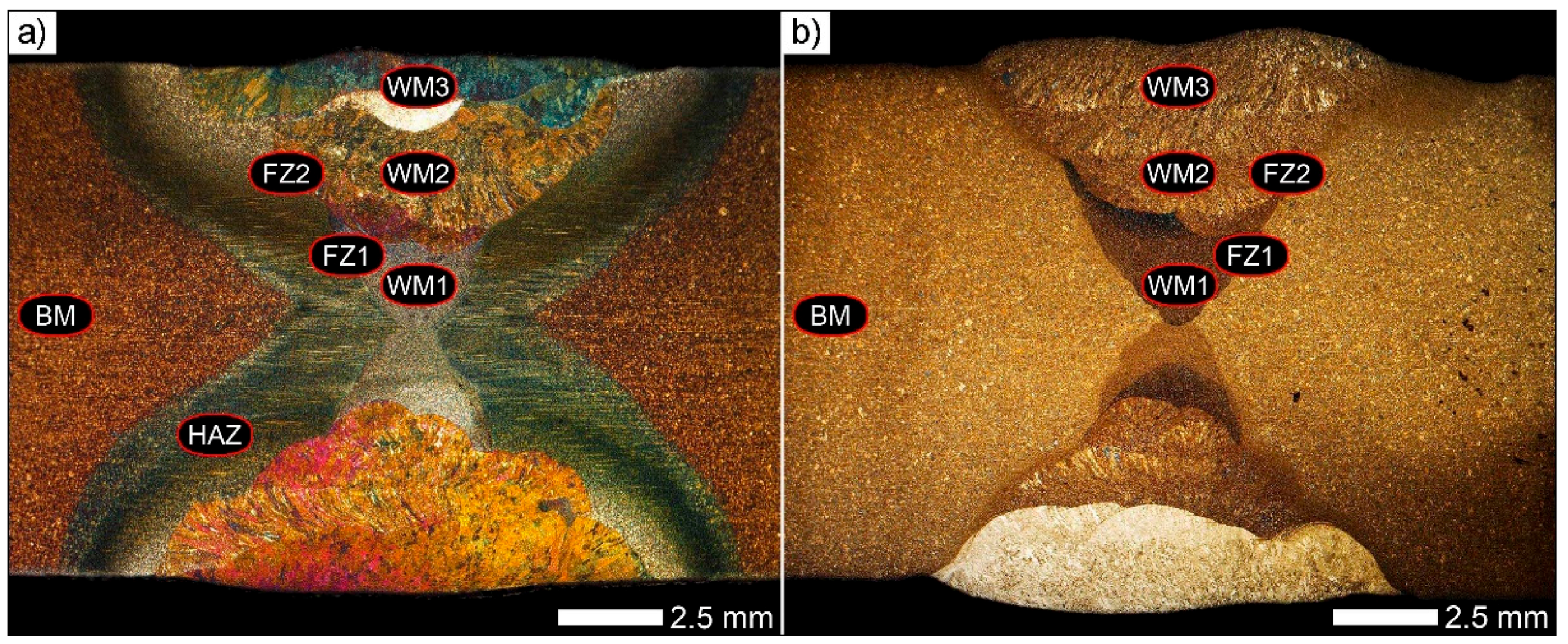
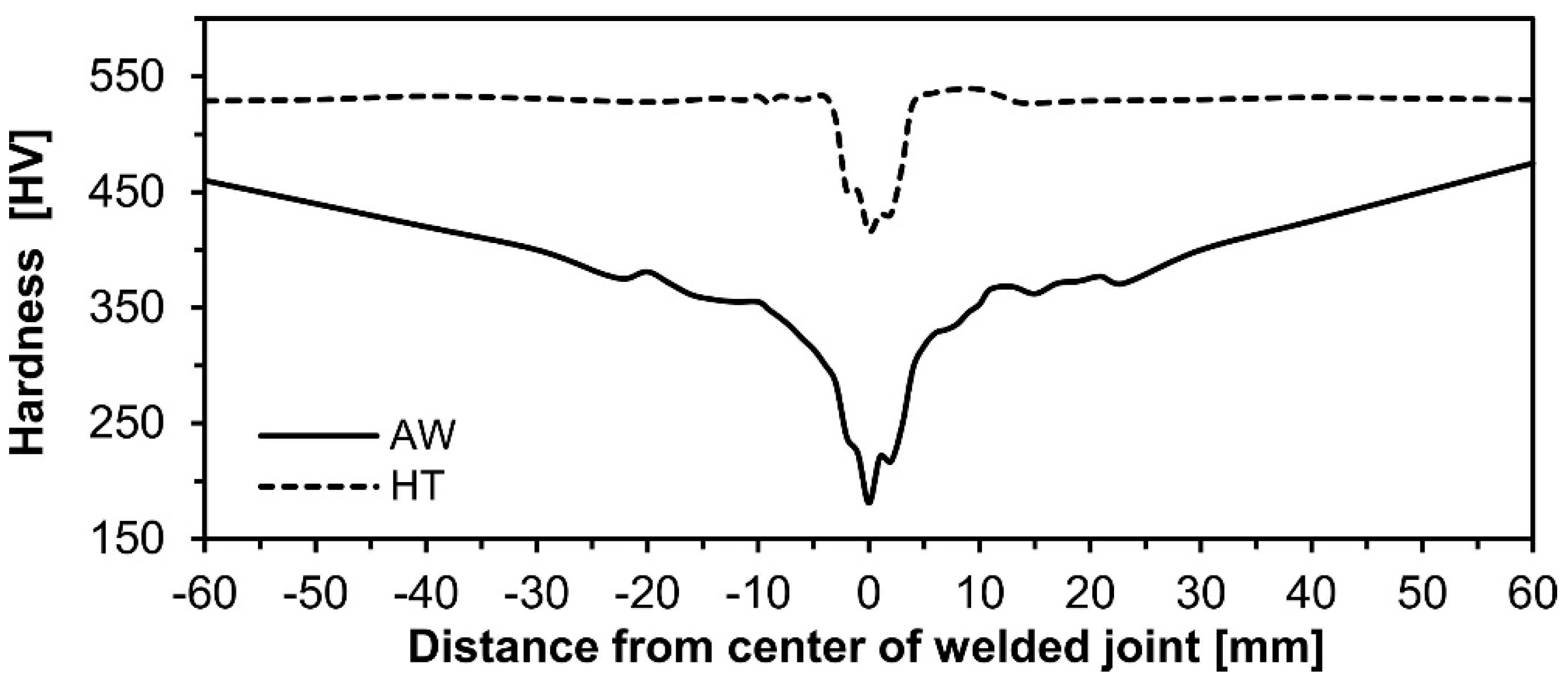
The figures below show macroscopic images of the joints (Figure 3), hardness distributions (Figure 4, Figure 5 and Figure 6), and a review of the characteristic microstructures in their various zones (Figure 7, Figure 8, Figure 9, Figure 10, Figure 11, Figure 12, Figure 13 and Figure 14). It can be found on the grounds of the obtained results that welding caused variable structural changes in the steel Hardox 600, resulting in very wide zones of reduced hardness. These zones reach up to 80 mm from the weld axis deep to the base material (see Figure 4 and Figure 5). Width of this zone is mostly decided by the method and applied parameters and conditions of welding (interpass temperature). However, it should be emphasised that, from the viewpoint of the hardenability of the Hardox 600 steel (CEV = 0.76; Table 3 and Figure 1), application of the hardenability criteria commonly accepted for low-alloy steels can be questionable.
Therefore, in the authors’ opinion, in order to obtain a high-quality welded joint with mechanical properties correlated with those of the base material, it should be obligatory to consider post-welding heat treatment that would reconstruct the proper microstructure and material properties in the whole area of the joint. It is also possible to utilize specialised welding stations. A conclusion of the above considerations is that high mechanical parameters of Hardox 600 cannot be fully employed without any post-welding heat treatment, even with the use of high-energy welding techniques. Thus, the accepted assumptions of execution and qualitative evaluation of welded joints of this steel are based on the application of the above-mentioned heat treatment. The performed qualitative evaluation of the examined joints showed that the post-welding thermal treatment operations led to favourable structural changes within the entire joint.
After post-welding heat treatment, the material structure within the base material (BM in Figure 3) was martensitic, similar to that in the as-delivered condition, see Figure 7a,c. After welding (Figure 7b), this structure showed features characteristic to tempered sorbite.
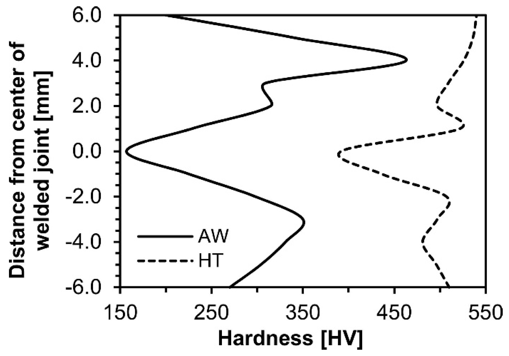
Material hardness in the BM zone was 370–380 HV after welding and ca. 530 HV after heat treatment, still significantly differing from the declared hardness of Hardox 600 in the as-delivered condition (minimum 670 HV, Table 1) which can be caused by its coarser martensite structure. However, it should be stressed that this parameter was not a primary issue in the authors’ considerations. As the main goal it was considered obtaining a uniform martensitic structure guaranteeing approximately constant hardness in the entire welded joint area. This goal was reached in the zone composed of the weld metal OK Aristorod 89 (Figure 4). In the central part of the weld, composed of the weld metal UltraMag only, somewhat reduced hardness was recorded, reaching ca. 400 HV (Figure 5 and Figure 6). This drop can be explained by the chemical composition of the weld metal being significantly different in composition from the other materials, affecting the properties both after welding and after heat treatment.
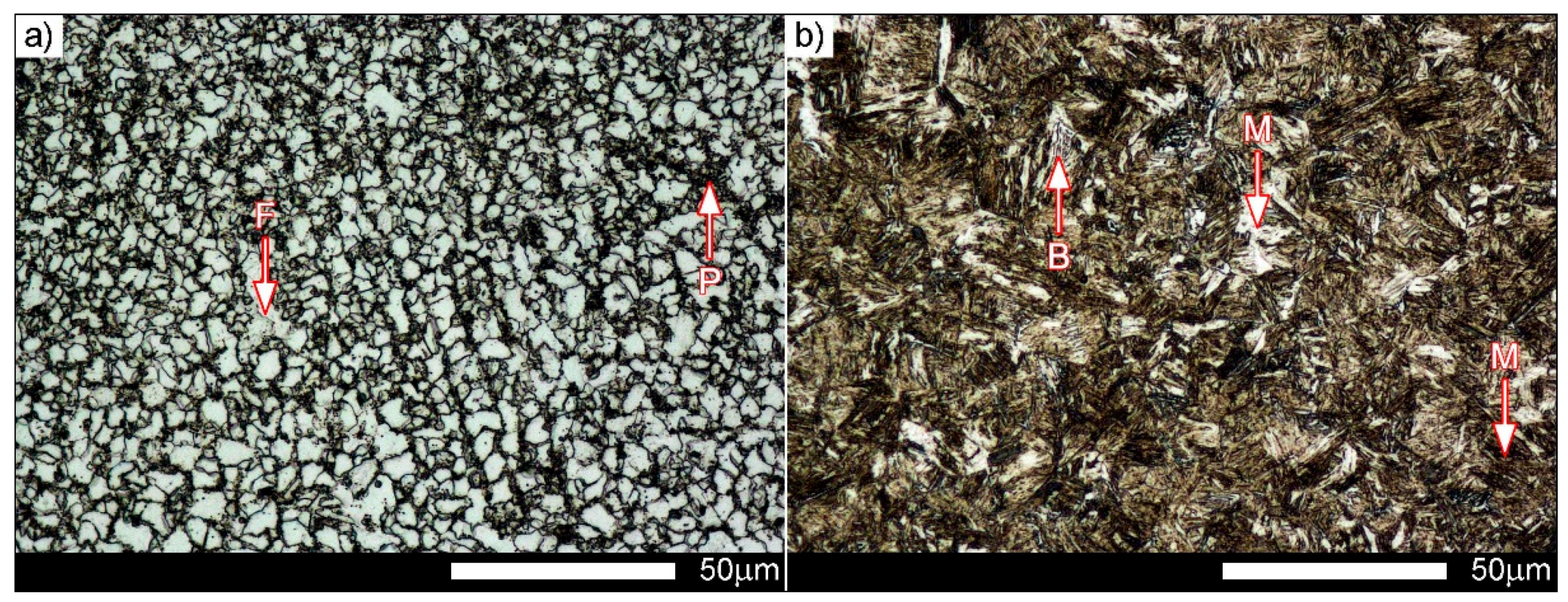
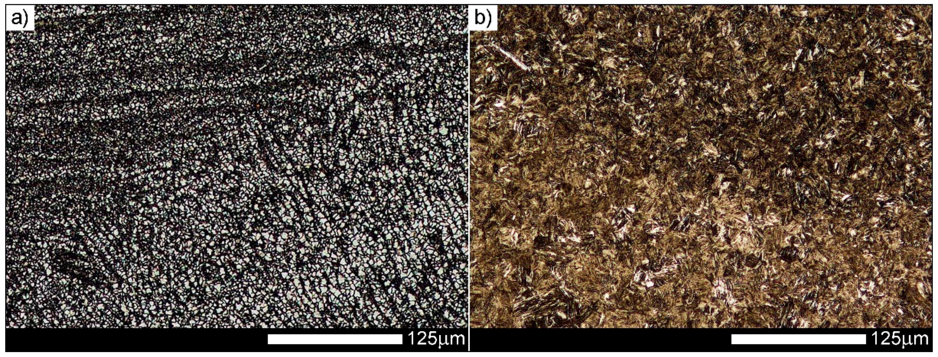
In the weld metal zone WM1 (Figure 3), directly after welding, structures typical for variable temperatures and cooling rates are observed. Microstructure of the joint is composed of granular ferrite with areas of pearlite, see Figure 8a. Morphology of the microstructure changes, starting from the fine-grained normalized structure next to the weld centre, through the structure close to that obtained at equilibrium cooling, to the structural characteristic for directional crystallisation. Hardness in this zone was ca. 180 HV. After heat treatment, microstructure in that zone was composed of tempered martensite with areas of upper bainite (see Figure 8b).
This structure indicates that material hardenability in this zone is much higher, resulting from the chemical composition of the weld metal. This is caused, first of all, by diffusion of carbon from Hardox 600 to the weld metal. This conclusion is confirmed by the structural changes in the zones above WM1, where, in both conditions of the joints, increased part of bainitic structures is clearly observed, see Figure 9.
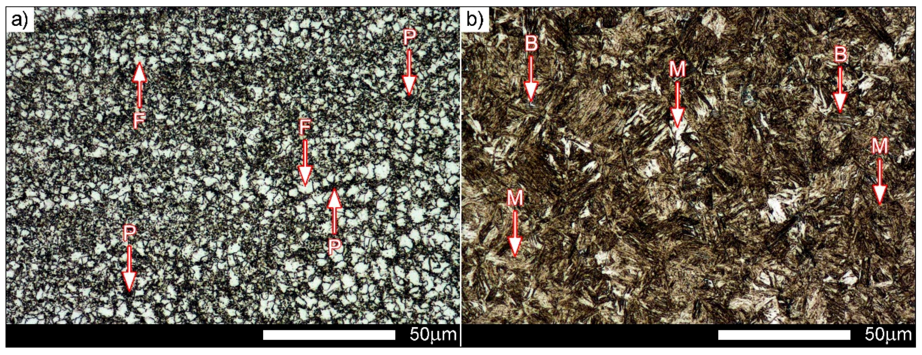
Directly after welding (Figure 9a), the microstructure in the weld metal zone WM2 is composed of tempered martensite with needle-like ferrite, locally with features of upper bainite, and also sparse colonies of troostite. Results of heat treatment of the WM2 zone are similar to those found in WM1. Microstructures are composed mostly of tempered martensite with bainitic areas, see Figure 9b. Morphology of martensite in this zone indicates rather differentiated concentrations of carbon, which results in the presence of both needle-like and lath martensite. From the viewpoint of the mechanical properties, such microstructure can explain the satisfactory impact strength of the welding joint [45]. The cooling rate of the weld metal zones located next to the outside surface of the joint (WM3 in Figure 3) resulted in obtaining, after heat treatment, a somewhat banded microstructure of lath tempered martensite with areas of cryptoacicular martensite (see Figure 10b). Such diversification of the microstructure indicates that the performed operation of normalizing before hardening did not lead to complete homogenisation of the structure in the entire cross-section of the joint. However, in the WM3 zone after welding (Figure 10a), composed of needle-like ferrite with martensite, heat treatment resulted in similar hardness levels in this one and in the other zones of weld metal, see Figure 6. The recorded scatter of hardness values after heat treatment was 144 HV (392–536 HV) in this case, and as much as 306 HV (157–463 HV) after welding.
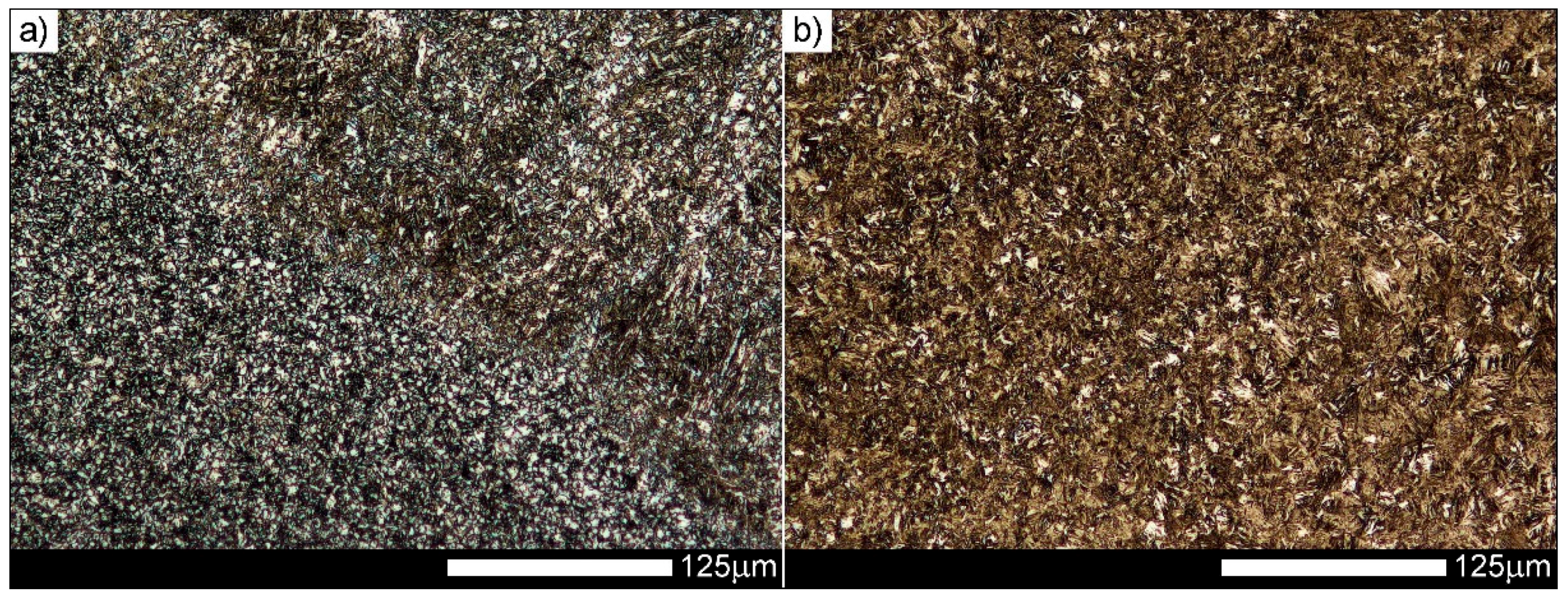
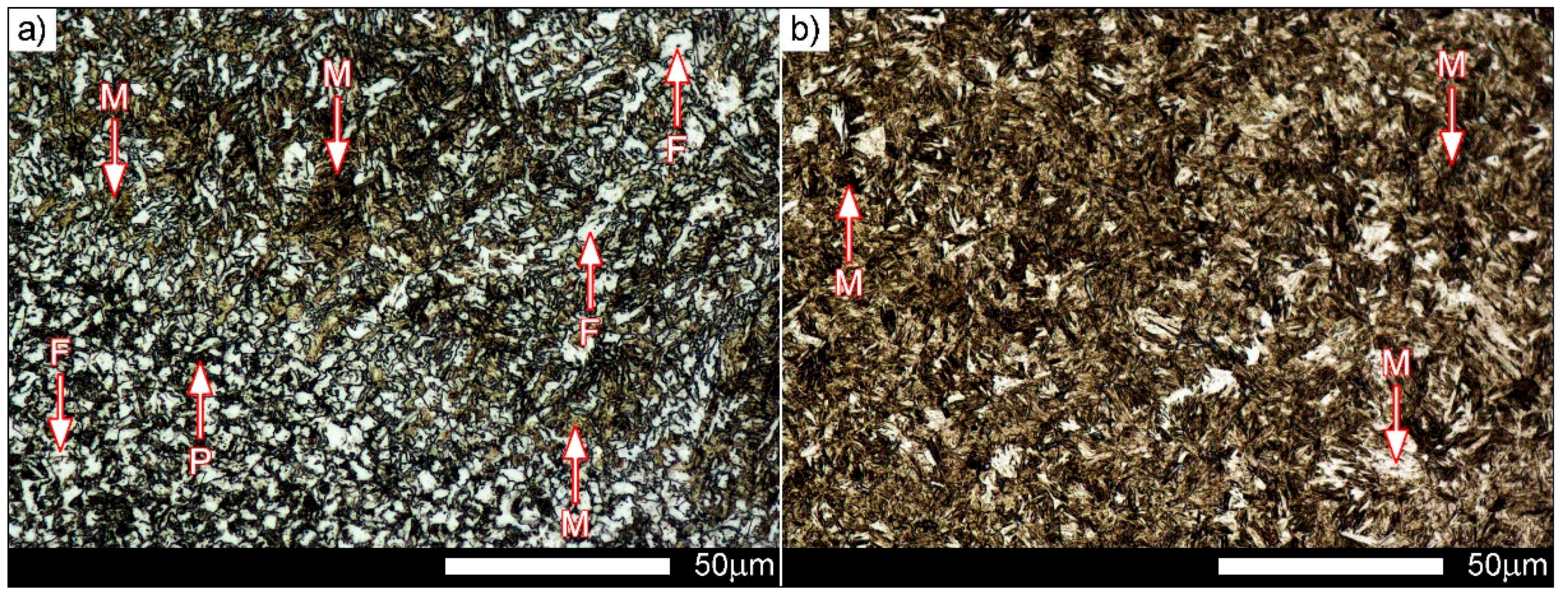
Microstructures of a fragment of the joint after welding (FZ1 in Figure 3), shown in Figure 11a and Figure 12a, are characterised by a clearly visible fusion line in that structural changes detrimental for mechanical properties can be observed. These changes can be generally defined as the presence of two morphologically different structures arranged approximately perpendicularly to each other.
On one hand, the structure of the weld metal is approximately dendritic (right side in Figure 11a) and, on the other hand, the structure of the welded material in HAZ is clearly banded, ferritic-pearlitic-martensitic (left side in Figure 11a). It should be especially emphasised that the observed banding is a result of welding operation and is not observed in the structure of the base material. At the same time, it is a characteristic feature of the microstructure of the entire heat-affected zone shown in Figure 14a and Figure 15. The performed heat-treatment operations are structurally equalized in the entire fusion zone FZ1, making it fine-lath tempered martensite with bainitic areas (see Figure 11b and Figure 12b). However, in the FZ2 zone (Figure 3) after welding (OK Aristorod 89 area), quite a wide line of structural changes is observed (central area in Figure 13a). On its whole length, the martensitic structure with small parts of needle-like ferrite and bainite is observed, see Figure 14a. After post-welding heat treatment, the microstructure of the entire FZ2 zone was homogenised to lath martensite (see Figure 13b and Figure 14b). As a result, it is impossible to distinguish the fusion line unambiguously.
3.3. Results of Fractographic Analysis
Fractures of representative specimens after tensile and impact testing are shown in Figure 16 and Figure 17. Microscopic analysis showed significant differences in the fracture structures depending on the heat treatment [46,47,48,49,50,51,52].
The fracture obtained in a static tensile test of a specimen of the untreated welding joint shows developed topography and distinct zonality (see Figure 16a). In the central part of the fracture, a transverse crack running through its entire width can be seen. The fracture of a heat-treated specimen also shows developed topography and zonality, clearly determining the areas of the base material and two kinds of weld metals (see Figure 16b). However, this fracture is free from cracks and its central part is elevated, which can show that the fracture was created by shearing along the direction of maximum shear stresses acting at 45° to the direction of maximum tensile stresses.
Fractures after impact testing show significant parts of external plastic zones. The central part of the fracture of an untreated welded joint is characterised by distinct striped structure and the fracture is considerably plastically deformed, which evidences high expenditure of energy during its creation, see Figure 15c. In turn, the central part of the fracture of a heat-treated welded joint is evenly rough, see Figure 15d. In order to reveal microstructure details of individual zones, fractures of impact specimens were subjected to further observations using SEM.
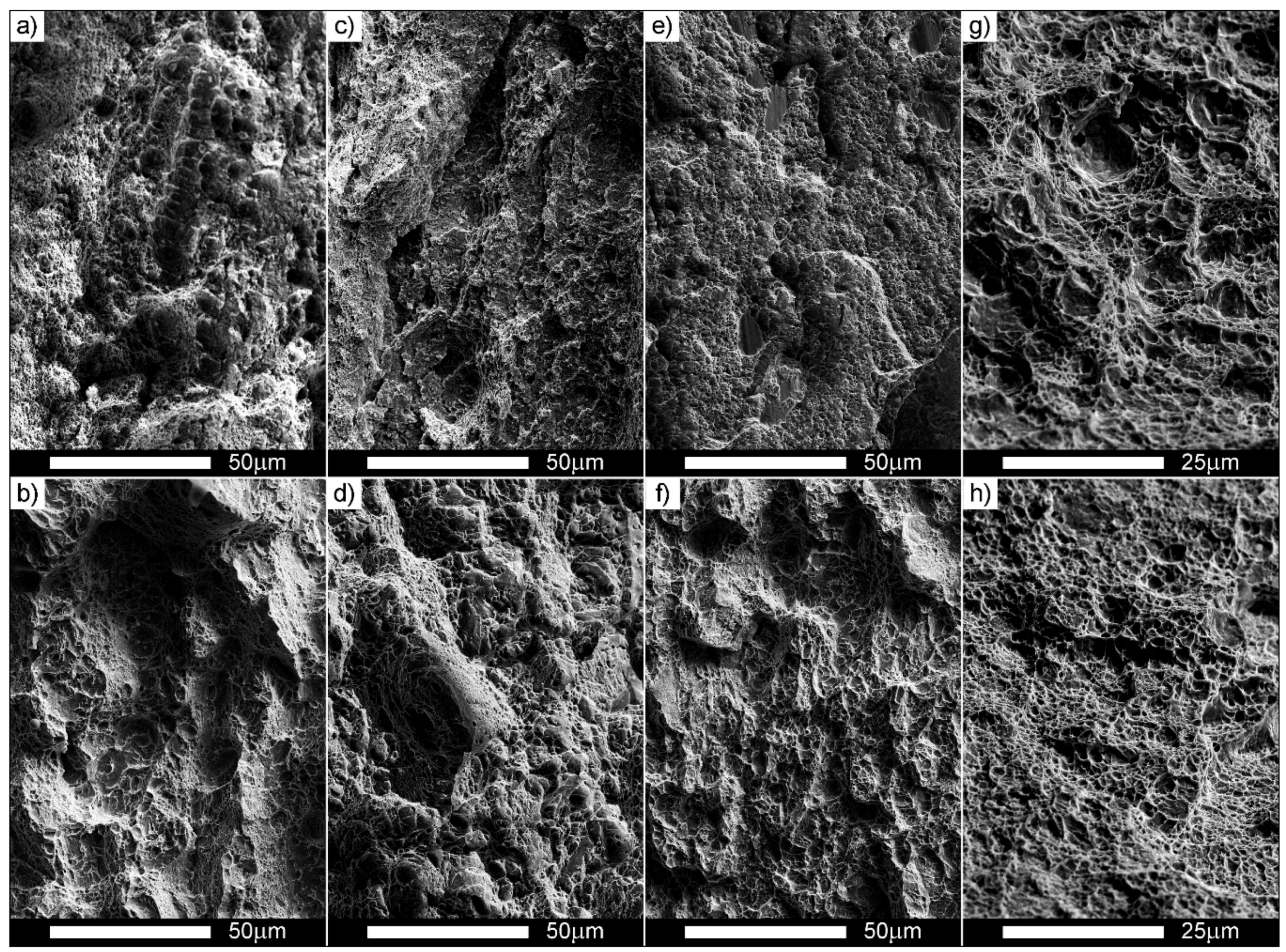
Below the notches, transcrystalline fractures of both untreated (Figure 17a) and heat-treated (Figure 17b) welded joints are of a ductile nature, with irregularities on interfacial surfaces. Cavities are of various sizes and fragments of phases resulting from alloying microadditives are visible in larger images of them, acting as stress concentrators initiating microcracks.
Qualitative differences in structures of the fractures depending on the applied heat treatment of the welded joints are visible in the central and in final fracture zones. The fracture in the central zone of an untreated specimen is ductile, with developed topography, numerous transverse cracks and conglomerates of small offsets, see Figure 16c. The areas with a “dimpled” structure, typical for a ductile fracture, are separated with plastic areas witch characteristic banded arrangement of offsets, where dimples show a “scaly” structure (see Figure 17h). Such a fracture is created as a result of slips followed by decohesion and microcracks in the planes {100} [46]. The cracks connect with each other by shearing the separating walls, which gives a characteristic view of their fracture in the form of overlapping scales. The pits have parabolic contours, which shows action of shearing forces during the creation of the fracture. The fracture is initiated by plastic deformation (slip), but cracks themselves basically propagate along determined crystallographic planes.
In the final fracture zone (Figure 17e) of the untreated joint, besides partial tears, characteristic features of a ductile fracture, like dimples and cleavage cracks, are revealed. The central (Figure 17d) and final fracture zones (Figure 17f) of the heat-treated joint show features of a mixed ductile-cleavage fracture. Small, narrow cleavage areas are separated with wide ridges with a dimpled structure, typical for a ductile fracture. Even if the facets are similar to those cleavage-type because of the occurring “river” relief, identification of crystallographic planes is almost impossible. Thus, it cannot be said in this case about a typical quasi-cleavage fracture, because the “river” system meandering on a larger area makes dimples that can be similar to those present in a ductile surface. In addition, offsets can be created on a mixed fracture. Creation of the offsets is accompanied by an increase of the energy absorbed during cracking, which results in decreased brittleness. The presence of an offset results in a change of the crack propagation direction. Consequently, propagation of the crack is delayed on some lengths, resulting in bending of the front; neighbouring offsets merge and create a “river” system.
Side zones of both specimens (Figure 17g,h) are ductile fractures with different-sized dimples, while larger-sized differences occur in side fracture zones of the untreated joint. The configuration of the surface is typical for a ductile fracture, composed of a system of conical elevations and dimples showing marks of plastic deformations. In larger cavities, non-metallic inclusions can be observed (Figure 17g), which were cracking initiators. Moreover, areas with a partially “scaly” structure can be observed in this zone.
4. Discussion
It can be found on the grounds of the performed laboratory examinations that sheet steel Hardox 600 with martensitic structure can be joined by welding. It was shown that it is possible to obtain a durable welded joint free of imperfections, characterised by good mechanical properties. Moreover, it is possible to reconstruct the microstructure and hardness in the entire area of the welded joint by using post-welding heat treatment consisting of quenching and low-temperature tempering preceded by normalization. Application—together with these heat-treatment operations—of proper weld metals makes it possible to eliminate low-hardness zones practically from the whole welded joint area. This means that, in relation to the as-delivered condition, such a welded joint should show higher abrasive-wear resistance, as well as a much better combination of selected mechanical parameters.
From a theoretical point of view, it is also worth analyzing the possibility of obtaining welded joints with similar tensile strength as the base material. However, in practical terms, there would be a need to use welding materials with similar chemical compositions, as well as subjecting the joint to the same conditions of thermo-mechanical rolling as Hardox 600. However, due to insufficient metallurgical weldability, the use of welding materials with similar chemical compositions as Hardox 600, eliminates the possibility of obtaining a welded joint free of imperfections. In the context of the above considerations, obtaining a unitary value of Rm = 1562 MPa should be treated as a guideline for stabilizing the welding process. Obtaining the tensile strength of the welded joint approximately 78% of the tensile strength of the welded material indicates that, with using the presented welding technology and welding conditions, very high strengths can be achieved, significantly exceeding the values available in generally-accepted welding standards. However, from the viewpoint of a qualitative description of the considered welded joints, rather large scatters of the obtained tensile strength values, especially for heat-treated specimens should be noted. This was caused, first of all, by the fact that test welds were made by manual TIG welding. Nevertheless, in the authors’ opinion, that does not cancel cognitive values of the presented analyses, but encourages performing analogous research works with the use of an automated welding station that guarantees adequate reproducibility of welding conditions and parameters. It should be emphasised that the adoption of the above position would require simultaneous changes in the welding method. Therefore, the most advantageous solution to this problem would be to use automated MIG/MAG welding or hybrid welding. Nevertheless, it should be emphasised that, in the case of hybrid welding, consideration should be given to many additional technological factors, such as those associated with conducting the welding process itself, to designing and executing welded joints, in accordance with the outlined scheme.
In the authors’ opinion, it is possible to develop a complex technology of welding this type of steel, guaranteeing much higher mechanical properties than those shown in this article, and even moving the location of the final fracture completely outside the weld-affected zone.
5. Conclusions
Generally, the determined properties of welded joints of Hardox 600 can be characterised as follows:
- −
- The welding operation causes variable microstructure changes in the entire joint, resulting in lowered hardness in comparison to the base material. These changes can be characterised as a decomposition of the original Hardox 600 structure, as a result of thermal action, to structures characteristic for quenching and tempering, as well as to morphologically non-homogeneous hardening structures.
- −
- As a result of the performed post-welding heat treatment, structural transformation occurred in the entire area of the joint consisting, first of all, in replacement of the “degraded” structure by the structure morphologically similar to that of as-delivered steel Hardox 600.
- −
- Tensile strength values of the welded joint (871 MPa) and very high impact strength (163 J/cm2) confirm the possibility to weld the Hardox 600 steel, even if this material has a high carbon equivalent (CEV) much higher than the value of 0.45 accepted as safe. This statement was additionally confirmed by fractographic analysis of impact-test specimens.
- −
- Mechanical properties of the Hardox 600 joints after heat treatment showed that the initial properties of the steel can be reconstructed with respect to both microstructures and selected mechanical properties. It was shown that, after heat treatment, the average tensile strength is 1386 MPa, however, the maximum tensile strength that can be reached is 1562 MPa, i.e., 78% of the nominal value of Hardox 600, which should be treated as a guideline for stabilizing the welding process. The tensile strength value of 1562 MPa can be treated in spite of the high-strength properties of the welded joint, and favourable plastic properties were maintained, manifested by quite high impact strength (42 J/cm2) and dominating part of the ductile fracture revealed by fractographic analysis.
- −
- The information obtained from this research, referring to the application of additional heat-treatment of welded joints of Hardox 600, clearly indicate the possibility of regenerating their “degraded” structural and mechanical properties.
Author Contributions
Łukasz Konat contributed reagents/materials/analysis tools, conceived and designed the experiments, performed experiments, analysed data, wrote the paper; Beata Białobrzeska contributed reagents/materials/analysis tools, analysed data, wrote the paper; Paweł Białek contributed reagents/materials/analysis tools, designed and performed the experiments.
Conflicts of Interest
The authors declare no conflict of interest.
References
- Adamczyk, J. Engineering of Metallic Materials; Wydawnictwo Politechniki Śląskiej: Gliwice, Poland, 2004. (In Polish) [Google Scholar]
- Zdravecka, E.; Tkacova, J.; Ondac, M. Effect of microstructure factors on abrasion resistance of high-strength steels. Res. Agric. Eng. 2014, 60, 115–120. [Google Scholar]
- Hui, W.; Dong, H.; Weng, Y.; Shi, J.; Nie, Y.; Chu, Z.; Chen, Y. Delayed fracture behavior of ultrafine grained high strength steel. Acta Metall. Sin. 2004, 40, 561–568. [Google Scholar]
- En, Z.; Jumaev, N.; Usmanova, M.M.; Kim, H.J.; Ho, J.W.; Jang, J.; Brenizer, J.S. Application of SSNTDs for study of boron distribution in alloys. Radiat. Meas. 1997, 28, 363–368. [Google Scholar] [CrossRef]
- Hansson, P.; Lowgren, C. Properties of modern wear resistant steels. Svetsen 1990, 1, 58–61. [Google Scholar]
- Badinier, G. The Effect of Carbon Segregation and Carbide Precipitation on the Mechanical Response of Martensite. Ph.D. Thesis, University of British Columbia, Vancouver, BC, Canada, May 2013. [Google Scholar]
- Kuziak, R.; Kawalla, R.; Waengler, S. Advanced high strength steels for automotive industry. Arch. Civ. Mech. Eng. 2008, 8, 103–117. [Google Scholar] [CrossRef]
- Adamiak, M.; Górka, J.; Kik, T. Comparison of abrasion resistance of selected constructional materials. J. Achiev. Mater. Manuf. Eng. 2009, 37, 375–380. [Google Scholar]
- Matlock, D.K.; Speer, J.G. Third generation of AHSS: Microstructure design concepts. In Microstructure and Texture in Steels; Haldar, A., Suwas, S., Bhattacharjee, D., Eds.; Springer: London, UK, 2009; pp. 185–205. ISBN 978-1-84882-454-6. [Google Scholar]
- Ilsenburger Grobblech GmbH. Available online: http://www.ilsenburger-grobblech.de/fileadmin/mediadb/ilg/infocenter/downloads/werkstoffblaetter/eng/abrasion_resistant_brinar400.pdf (accessed on 9 March 2017).
- Ilsenburger Grobblech GmbH. Available online: http://www.ilsenburger-grobblech.de/fileadmin/mediadb/ilg/infocenter/downloads/werkstoffblaetter/eng/abrasion_resistant_brinar500.pdf (accessed on 9 March 2017).
- Hardox Wear Plate-Wear and Abrasion Resistant Steel–SSAB. Available online: http://www.ssab.pl/produkty/marki/hardox (accessed on 9 March 2017).
- Hardox 600 Wear Plate, Abrasion Resistant Steel-Stal-Hurt. Available online: http://www.stal-hurt.com/hardox-trudnoscieralne-blachy/hardox600.html (accessed on 9 March 2017).
- Manufacturer of Abrasion Resistant Parts and Fixtures–Multialloy. Available online: http://www.multialloy.com.br/ing/produtos/pdf/Creusabro_8000.pdf (accessed on 9 March 2017).
- The Steel Service Centre–Flinkenberg Steel. Available online: http://www.flinkenberg.fi/wp-content/uploads/DATASHEET-XAR600.pdf (accessed on 9 March 2017).
- Bugłacki, H.; Smajdor, M. Mechanical properties of abrasion—Resistant Hardox 400 and their welded joints. Adv. Mater. Sci. 2003, 3, 5–8. [Google Scholar]
- Mazur, M.; Ulewicz, R.; Bokuvka, O. The impact of welding wire on the mechanical properties of welded joints. Mater. Eng. 2014, 21, 122–128. [Google Scholar]
- Brezová, E.; Mäsiar, H.; Radic, P. Welding of high strength materials used in the manufacture of special equipment. Univ. Rev. 2014, 8, 51–61. [Google Scholar]
- Uzunali, U.Y.; Cuvalci, H. The effects of post weld heat treatment on the mechanical properties of tempered martensite and high strength steel welded joints. In Proceedings of the 2015 World Congress on Advances in Structural Engineering and Mechanics (ASEM15), Incheon, Korea, 25–29 August 2015. [Google Scholar]
- Pękalski, G.; Haimann, K.; Konat, Ł.; Koniarek, K.; Krugła, M.; Mroczkowski, L.; Orłowski, J.; Oskwarek, M.; Ptak, T.; Szymczak, H. Material Testing of Hardox 400 and Hardox 500; Series SPR 10 Report; Institute of Materials Science and Technical Mechanics: Wroclaw, Poland, 2005. (In Polish) [Google Scholar]
- Cegiel, L.; Konat, Ł.; Pawłowski, T.; Pękalski, G. Hardox steels—New-generation constructional materials of surface-mining machines. Węgiel Brunatny 2006, 3, 24–29. (In Polish) [Google Scholar]
- Konat, Ł.; Pękalski, G.; Oskwarek, M. Macro- and microstructural properties of welded joints of Hardox 400 and Hardox 500 steels. In Proceedings of the XIX Scientific Conference on Development Problems of Working Machines, Zakopane, Poland, 23–26 January 2006. [Google Scholar]
- Konat, Ł. Structures and Properties of Hardox Steels and their Application Possibilities in Conditions of Abrasive Wear and Dynamic Loads. Ph.D. Thesis, Wroclaw University of Technology, Wroclaw, Poland, 2007. (In Polish). [Google Scholar]
- Dudziński, W.; Konat, Ł.; Pękalski, G. Structural and strength characteristics of wear-resistant martensitic steels. Arch. Foundry Eng. 2008, 8, 21–26. [Google Scholar]
- Dudziński, W.; Konat, Ł.; Pękalski, G. Modern constructional steels. In Maintenance Strategy of Surface Mining Machines and Facilities with High Degree of Technical Degradation; Dudek, D., Ed.; Publishing House of Wroclaw University of Technology: Wroclaw, Poland, 2013; pp. 346–366. (In Polish) [Google Scholar]
- Oskwarek, M. Structural features and susceptibility to cracking of welded joints of Hardox 400 and Hardox 500 steels. In Proceedings of the IV Students’ Science Conference: Human-Civilisation-Future, Wroclaw, Poland, 22–24 May 2006; Volume 2, pp. 115–120. [Google Scholar]
- Tasak, E. Metallurgy and Metal Science of Welded Joints; AGH University of Science and Technology: Kraków, Poland, 1985. (In Polish) [Google Scholar]
- Pilarczyk, J. (Ed.) Engineer’s Manual—Welding Technology; WNT: Warsaw, Poland, 2003. (In Polish) [Google Scholar]
- Frydman, S.; Konat, Ł.; Pękalski, G. Structure and hardness changes in welded joints of Hardox steels. Arch. Civ. Mech. Eng. 2008, 8, 15–27. [Google Scholar] [CrossRef]
- Dudziński, W.; Konat, Ł.; Pękalska, L.; Pękalski, G. Structures and properties of Hardox 400 and Hardox 500 steels. Mater. Eng. 2006, 3, 139–142. (In Polish) [Google Scholar]
- Konat, Ł.; Pękalski, G. Structures and selected properties of Hardox steels in the context of their use in surface mining machinery construction. In Proceedings of the XV International Symposium on Mine Planning & Equipment Selection (MPES 2006), Torino, Italy, 20–22 September 2006. [Google Scholar]
- Łętkowska, B. Influence of Heat Treatment on Structure and Selected Properties of B27 and 28MCB5 Steels. Ph.D. Thesis, Wroclaw University of Technology, Wroclaw, Poland, 2013. (In Polish). [Google Scholar]
- Dudziński, W.; Białobrzeska, B.; Konat, Ł. Comparative analysis of structural and mechanical properties of selected low-alloy boron-containing abrasive-wear resistant steels. In Polish Metallurgy in the Years 2011–2014; Świątkowski, K., Ed.; Akapit: Kraków, Poland, 2014; pp. 871–888. (In Polish) [Google Scholar]
- Pawlak, K.; Białobrzeska, B.; Konat, Ł. The influence of austenitizing temperature on prior austenite grain size and resistance to abrasion wear of selected low-alloy boron steel. Arch. Civ. Mech. Eng. 2016, 16, 913–926. [Google Scholar] [CrossRef]
- Białobrzeska, B.; Konat, Ł.; Jasiński, R. The influence of austenite grain size on the mechanical properties of low-alloy steel with boron. Metals 2017, 7, 26. [Google Scholar]
- Frydman, S.; Konat, Ł.; Białobrzeska, B.; Pękalski, G. Impact resistance and fractography of low-alloy martensitic steels. Arch. Foundry Eng. 2008, 8, 89–94. [Google Scholar]
- Dudziński, W.; Konat, Ł.; Białobrzeska, B. Fractographic analysis of selected boron steels subjected to impact testing. Arch. Metall. Mater. 2015, 60, 2373–2378. [Google Scholar] [CrossRef]
- Napiórkowski, J.; Konat, Ł.; Ligier, K. The structural properties and resistance to abrasive wear in soil of Creusabro steel. Tribologia 2016, 47, 105–119. [Google Scholar]
- Konat, Ł.; Napiórkowski, J.; Kołakowski, K. Resistance to wear as a function of the microstructure and selected mechanical properties of microalloyed steel with boron. Tribologia 2016, 47, 101–114. [Google Scholar]
- Graville, B.A. Cold Cracking in welds in HSLA steels, welding of HSLA (Microalloyed) structural steels. In Proceedings of the AIM/ASM Conference, Rome, Italy, 9–12 November 1976. [Google Scholar]
- ESAB. Available online: http://www.skladbaildon.pl/PDF-2012/1-pridavne-svarovaci-materialy/D18/OK_Aristorod_89.pdf (accessed on 9 September 2016).
- Lincoln Electric. Available online: http://www.lincolnelectric.com/assets/global/products/consumableeu_migwires-ultramag-ultramag/ultramag-pl.pdf (accessed on 9 September 2016).
- Wyrzykowski, J.W.; Pleszakow, E.; Sieniawski, J. Deformation and Cracking of Metals; WNT: Warszawa, Poland, 1999. (In Polish) [Google Scholar]
- Lin, C.-M.; Lu, C.-H. Effects of tempering temperature on microstructural evolution and mechanical properties of high-strength low-alloy D6AC plasma arc welds. Mater. Sci. Eng. A 2016, 676, 28–37. [Google Scholar] [CrossRef]
- Wang, C.; Wang, M.; Shi, J.; Hui, W.; Dong, H. Effect of Microstructure Refinement on the Strength and Toughness of low alloy martensitic steel. J. Mater. Sci. Technol. 2007, 23, 659–664. [Google Scholar]
- Maciejny, A. Brittleness of Metals; Publishing House Śląsk: Katowice, Poland, 1973. (In Polish) [Google Scholar]
- Mills, K.; American Society for Microbiology (ASM). ASM Handbook Volume 12: Fractography, 9th ed.; ASM International: Russell, OH, USA, 1987. [Google Scholar]
- Ravichandran, K.S.; Vasudevan, A.K. Fracture resistance of structural alloys. In ASM Handbook Volume 19: Fatigue and Fracture; ASM International: Russell, OH, USA, 1996; pp. 381–392. [Google Scholar]
- Horn, R.M.; Ritchie, R.O. Mechanisms of tempered martensite embrittlement in low alloy steels. Metall. Trans. A 1978, 9, 1039–1053. [Google Scholar] [CrossRef]
- Maity, S.K.; Kawalla, R. Ultrahigh strength steel: Development of mechanical properties through controlled cooling. In Heat Transfer—Engineering Applications; Vikhrenko, V., Ed.; InTech: Shanghai, China, 2011; pp. 309–336. [Google Scholar]
- Vishnevsky, C.; Steigerwald, E.A. Influence of Alloying Elements on the Toughness of low Alloy Martensitic High Strength Steels; Final Technical Report; TRW Inc.: Cleveland, OH, USA, 1968. [Google Scholar]
- El-Bitar, T.; Gamilb, M.; Mousab, I.; Helmy, F. Development of carbon—Low alloy steel grades for low temperature applications. Mater. Sci. Eng. A 2011, 528, 6039–6044. [Google Scholar] [CrossRef]
Figure 1.
Susceptibility to cracking in function of carbon concentration and carbon equivalent of selected low-alloy abrasive-wear resistant steels: H—Hardox; BR—Brinar; X—XAR; CR—Creusabro. Based on data in Table 3 and [40].

Figure 2.
Layout of Hardox 600 welded joints: (a) prepared sheet edges; and (b) building of weld metal during welding: A—weld metal UltraMag; B—weld metal Aristorod 89; 1, 2, 3—lines of hardness measurements.
Figure 2.
Layout of Hardox 600 welded joints: (a) prepared sheet edges; and (b) building of weld metal during welding: A—weld metal UltraMag; B—weld metal Aristorod 89; 1, 2, 3—lines of hardness measurements.
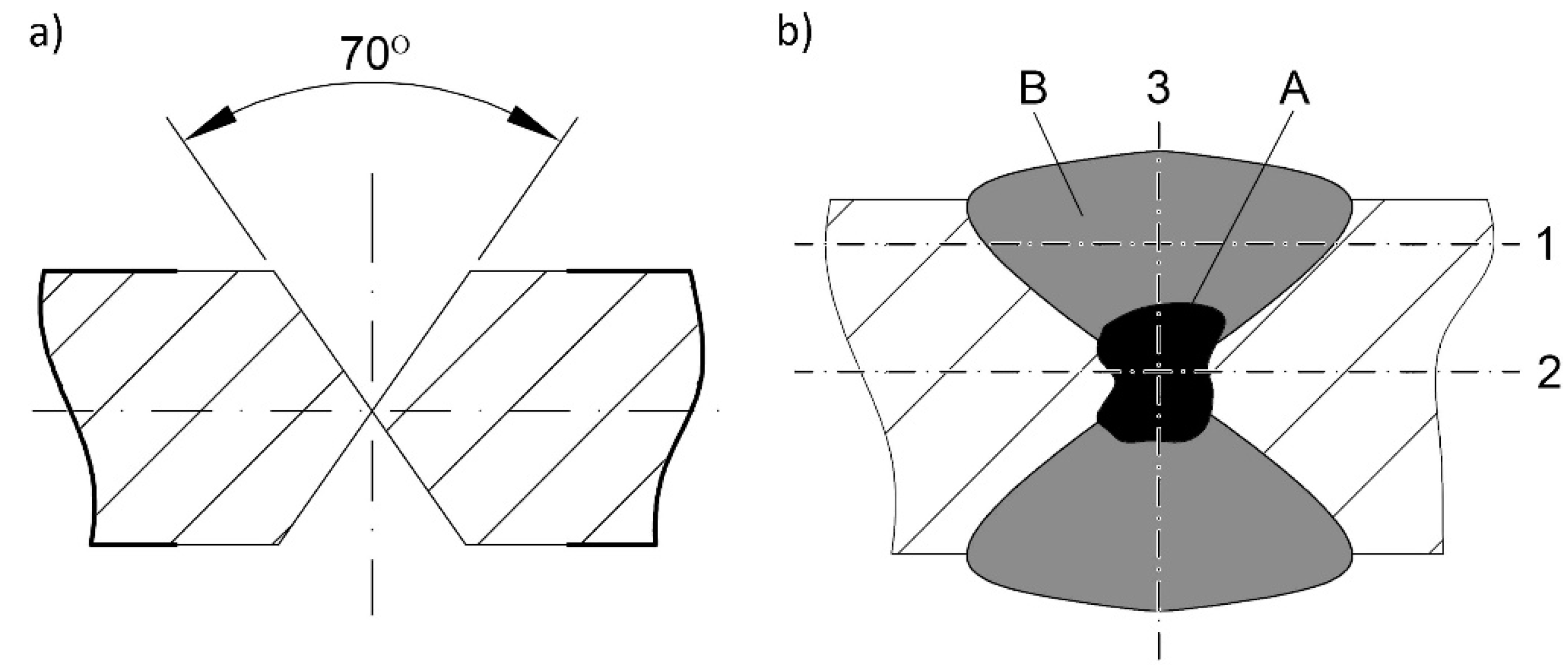
Figure 3.
Macroscopic images of cross-sections of exemplary welded joints of Hardox 600: (a) after welding; (b) after heat treatment. Designations: WM1—weld metal UltraMag; WM2/WM3—weld metal OK Aristorod 89; FZ—fusion zone; HAZ—heat-affected zone, BM—base material (ca. 20 mm from the weld axis). Light microscopy, etched with 2% HNO3.

Figure 4.
Hardness distribution in the welded joint of Hardox 600 along line 1 shown in Figure 2b: AW—after welding; HT—heat-treated.
Figure 4.
Hardness distribution in the welded joint of Hardox 600 along line 1 shown in Figure 2b: AW—after welding; HT—heat-treated.
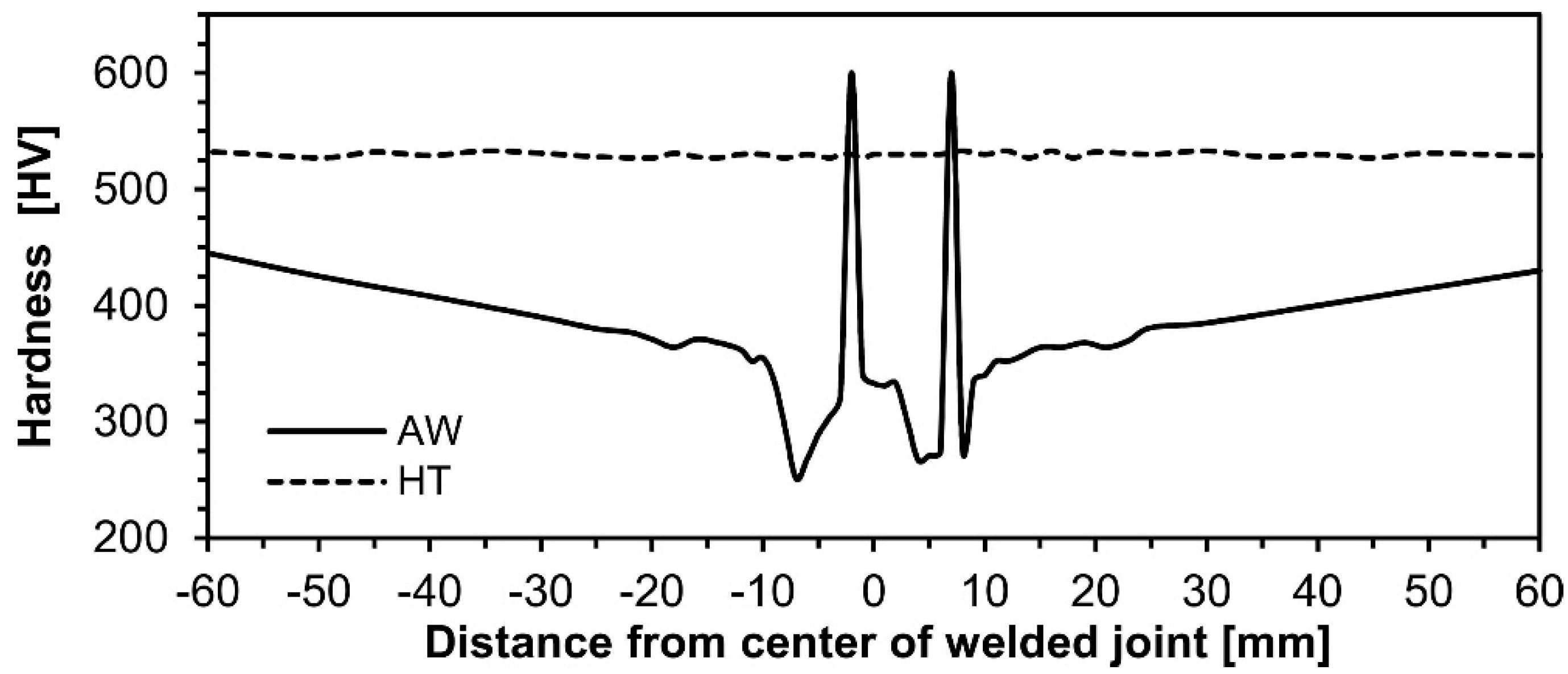
Figure 5.
Hardness distribution in the welded joint of Hardox 600 along line 2 shown in Figure 2b: AW—after welding; HT—heat-treated.
Figure 5.
Hardness distribution in the welded joint of Hardox 600 along line 2 shown in Figure 2b: AW—after welding; HT—heat-treated.

Figure 6.
Hardness distribution in the welded joint of Hardox 600 along line 3 shown in Figure 2b: AW—after welding, HT—heat-treated.
Figure 6.
Hardness distribution in the welded joint of Hardox 600 along line 3 shown in Figure 2b: AW—after welding, HT—heat-treated.

Figure 7.
Microstructures of the Hardox 600 joint within the base material ca. 20 mm from the weld axis—BM in Figure 3: (a) before welding; (b) after welding; and (c) after welding and heat treatment. Light microscopy, etched with 2% HNO3.
Figure 7.
Microstructures of the Hardox 600 joint within the base material ca. 20 mm from the weld axis—BM in Figure 3: (a) before welding; (b) after welding; and (c) after welding and heat treatment. Light microscopy, etched with 2% HNO3.
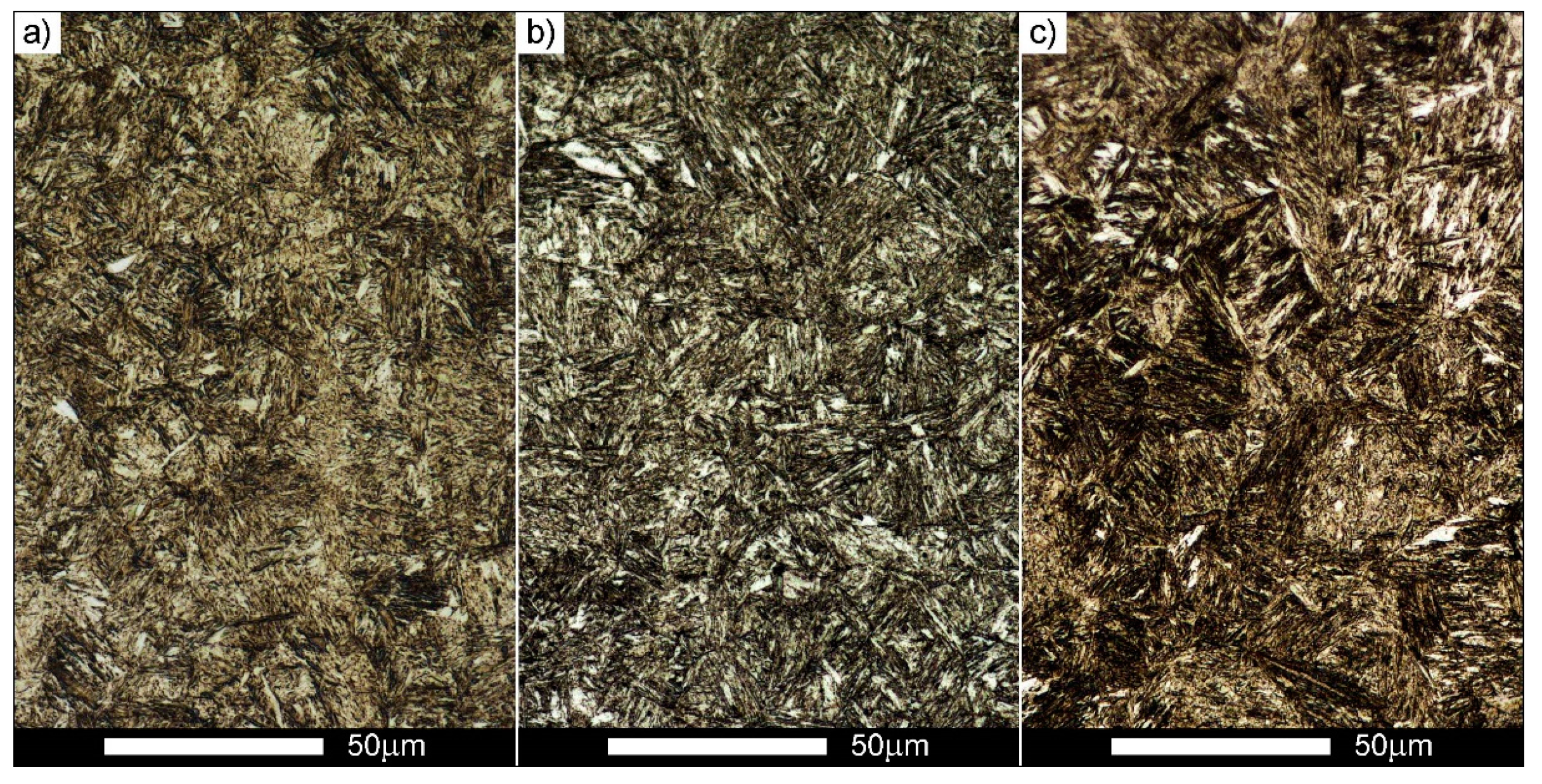
Figure 8.
Microstructures of the Hardox 600 joint within the weld metal zone—WM1 in Figure 3: (a) after welding; and (b) after welding and heat treatment. B—bainite, F—ferrite, M—martensite, P—pearlite. Light microscopy, etched with 2% HNO3.
Figure 8.
Microstructures of the Hardox 600 joint within the weld metal zone—WM1 in Figure 3: (a) after welding; and (b) after welding and heat treatment. B—bainite, F—ferrite, M—martensite, P—pearlite. Light microscopy, etched with 2% HNO3.

Figure 9.
Microstructures of the Hardox 600 joint within weld metal zone—WM2 in Figure 3: (a) after welding; and (b) after welding and heat treatment. B—bainite, F—ferrite, M—martensite, T—troostite. Light microscopy, etched with 2% HNO3.
Figure 9.
Microstructures of the Hardox 600 joint within weld metal zone—WM2 in Figure 3: (a) after welding; and (b) after welding and heat treatment. B—bainite, F—ferrite, M—martensite, T—troostite. Light microscopy, etched with 2% HNO3.
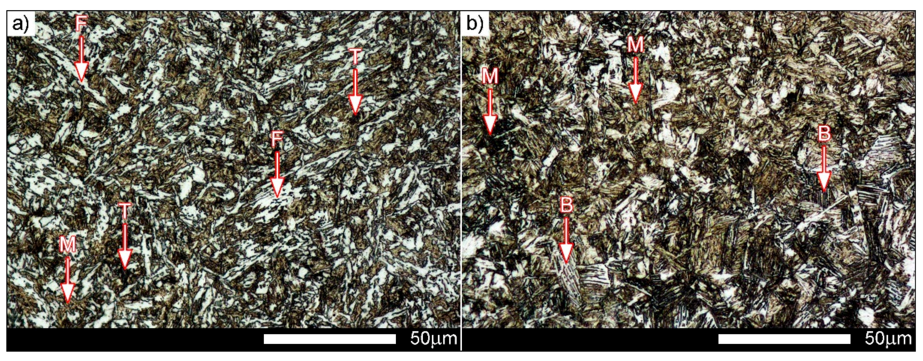
Figure 10.
Microstructures of the Hardox 600 joint within weld metal zone—WM3 in Figure 3: (a) after welding; and (b) after welding and heat treatment. F—ferrite, M—martensite. Light microscopy, etched with 2% HNO3.
Figure 10.
Microstructures of the Hardox 600 joint within weld metal zone—WM3 in Figure 3: (a) after welding; and (b) after welding and heat treatment. F—ferrite, M—martensite. Light microscopy, etched with 2% HNO3.
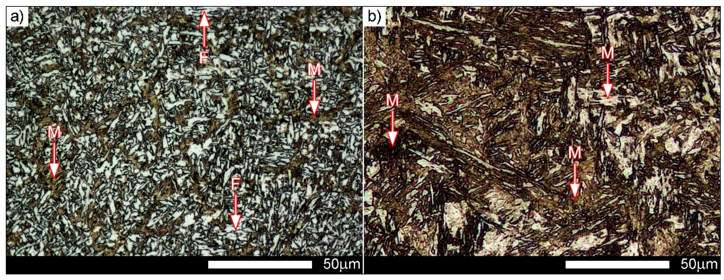
Figure 11.
Microstructures of the Hardox 600 joint within the fusion zone—FZ1 in Figure 3: (a) after welding; and (b) after welding and heat treatment. Light microscopy, etched with 2% HNO3.
Figure 11.
Microstructures of the Hardox 600 joint within the fusion zone—FZ1 in Figure 3: (a) after welding; and (b) after welding and heat treatment. Light microscopy, etched with 2% HNO3.

Figure 12.
Magnified images of the microstructures shown in Figure 11 (fusion zone FZ1): (a) after welding; and (b) after heat treatment. B—bainite, F—ferrite, M—martensite, P—pearlite. Light microscopy, etched with 2% HNO3.
Figure 12.
Magnified images of the microstructures shown in Figure 11 (fusion zone FZ1): (a) after welding; and (b) after heat treatment. B—bainite, F—ferrite, M—martensite, P—pearlite. Light microscopy, etched with 2% HNO3.

Figure 13.
Microstructures of the Hardox 600 joint within the fusion zone—FZ2 in Figure 3: (a) after welding; and (b) after welding and heat treatment. Light microscopy, etched with 2% HNO3.
Figure 13.
Microstructures of the Hardox 600 joint within the fusion zone—FZ2 in Figure 3: (a) after welding; and (b) after welding and heat treatment. Light microscopy, etched with 2% HNO3.

Figure 14.
Magnified images of microstructures shown in Figure 13 (fusion zone FZ2): (a) after welding; and (b) after welding and heat treatment. B—bainite, F—ferrite, M—martensite, P—pearlite. Light microscopy, etched with 2% HNO3.
Figure 14.
Magnified images of microstructures shown in Figure 13 (fusion zone FZ2): (a) after welding; and (b) after welding and heat treatment. B—bainite, F—ferrite, M—martensite, P—pearlite. Light microscopy, etched with 2% HNO3.

Figure 15.
Microstructures of the Hardox 600 joint within the heat-affected zone—HAZ in Figure 3. F—ferrite, M—martensite, P—pearlite. Light microscopy (various magnifications), etched with 2% HNO3.
Figure 15.
Microstructures of the Hardox 600 joint within the heat-affected zone—HAZ in Figure 3. F—ferrite, M—martensite, P—pearlite. Light microscopy (various magnifications), etched with 2% HNO3.
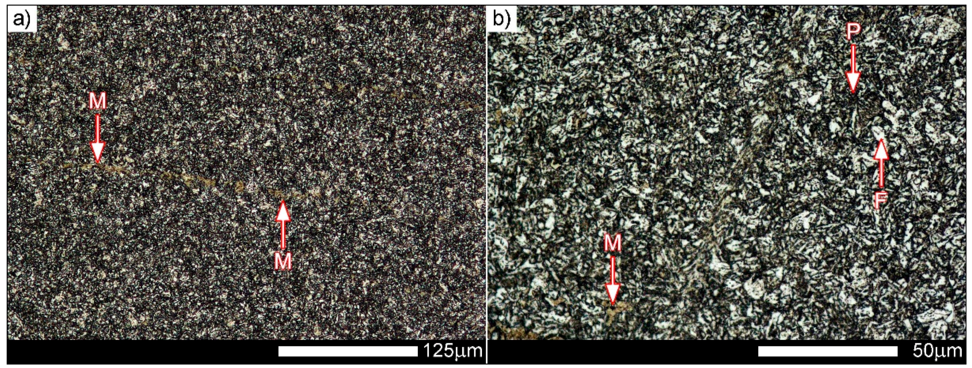
Figure 16.
Macroscopic images of fracture surfaces of selected Hardox 600 joints listed in Table 5: (a) AW-UTS-3; (b) HT-UTS-1; (c) AW-KCV-3; and (d) HT-KCV-1; C1/D1: zone below the notch; C2/D2: central zone of the fracture; C3/D3: final fracture zone; C4/D4: side zone of the fracture. Light microscopy, unetched.
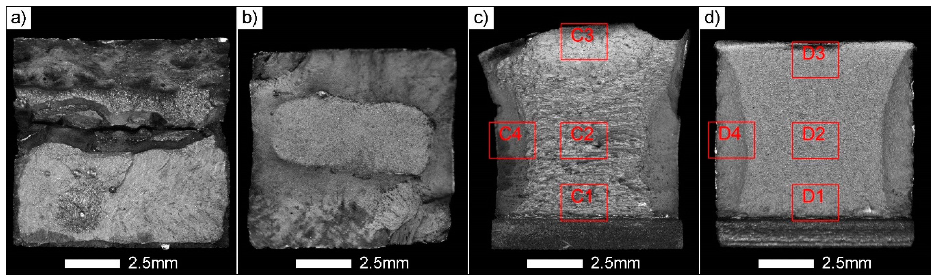
Figure 17.
Various fracture zones of the Hardox 600 joints shown in Figure 16c,d: (a) AW-KCV-3 below the notch (frame C1); (b) HT-KCV-1 below the notch (frame D1); (c) AW-KCV-3 in the central zone (frame C2); (d) HT-KCV-1 in the central zone (frame D2); (e) AW-KCV-3 in the final fracture zone (frame C3); (f) HT-KCV-1 in the final fracture zone (frame D3); (g) AW-KCV-3 in the side zone (frame C4); and (h) HT-KCV-1 in the side zone (frame D4). SEM, unetched.


Table 1.
Properties of selected low-alloy high-strength, abrasive-wear resistant steels [10,11,12,13,14,15].
| Steel | Rp0.2 | Rm | A5 | KCV−40 | HBW |
|---|---|---|---|---|---|
| (MPa) | (MPa) | (%) | (J/cm2) | ||
| Brinar 400 | 900 | 1200 | 12 | 25 (−20 °C) | 340–440 |
| Brinar 500 | 1350 | 1500 | 8 | 25 (−20 °C) | 480 |
| Hardox 400 | 1100 | 1250 | 10 | 56 | 370–430 |
| Hardox 450 | 1200 | 1400 | 10 | 50 | 425–475 |
| Hardox 500 | 1400 | 1550 | 10 | 46 | 470–530 |
| Hardox 600 | 1650 | 2000 | 7 | 25 | 570–640 |
| Hardox Extreme | --- | --- | --- | --- | 650–700 |
| Creusabro 8000 | 1250 | 1630 | 12 | ≥40 (−20 °C) | 430–500 |
| XAR 600 | 1700 | 2000 | 8 | 25 (−20 °C) | > 550 |
Rp0.2: yield strength; Rm: tensile strength; A5: percentage elongation after fracture; KCV−40: impact strength at temperature −40 °C; HBW: Brinell hardess.
Table 2.
Chemical compositions and declared carbon equivalents of selected low-alloy high-strength, abrasive-wear resistant steels [10,11,12,13,14,15].
| Steel Element | Brinar 400 | Brinar 500 | Hardox 400 | Hardox 450 | Hardox 500 | Hardox 600 | Hardox Extreme | Creusabro 8000 | XAR 600 |
|---|---|---|---|---|---|---|---|---|---|
| Max. Concentration (wt %) | |||||||||
| C | 0.18 | 0.28 | 0.14 | 0.21 | 0.27 | 0.45 | 0.47 | 0.28 | 0.40 |
| Mn | 2.00 | 1.50 | 1.60 | 1.60 | 1.60 | 1.00 | 1.40 | 1.60 | 1.50 |
| Si | 0.50 | 0.80 | 0.70 | 0.70 | 0.70 | 0.70 | 0.50 | - | 0.80 |
| P | 0.015 | 0.020 | 0.025 | 0.025 | 0.025 | 0.015 | 0.015 | 0.015 | 0.025 |
| S | 0.005 | 0.005 | 0.010 | 0.010 | 0.010 | 0.010 | 0.010 | 0.005 | 0.010 |
| Cr | 1.55 | 1.50 | 0.30 | 0.50 | 1.00 | 1.20 | 1.20 | 1.60 | 1.50 |
| Ni | - | - | 0.25 | 0.25 | 0.25 | 2.50 | 2.50 | ~0.40 | 1.50 |
| Mo | 0.60 | 0.40 | 0.25 | 0.25 | 0.25 | 0.80 | 0.80 | ≥0.20 | 0.50 |
| B | 0.005 | - | 0.004 | 0.004 | 0.004 | 0.004 | 0.005 | - | 0.005 |
| # (mm) | ≤80 | ≤60 | 3–10 | 10–20 | 4–13 | 8–30 | 8–20 | 5–60 | 15 |
| CEV 1 | - | - | 0.33 | 0.47 | 0.49 | 0.73 | 0.65 | - | 0.79 |
| CET 2 | - | - | 0.23 | 0.34 | 0.34 | 0.55 | 0.54 | - | 0.53 |
CEV = C + Mn/6 + (Cr + Mo + V)/5 + (Cu + Ni)/15; CET = C + (Mn + Mo)/10 + (Cr + Cu)/20 + Ni/40; #—sheet thickness for the given composition.1 CEV—carbon equivalent formula according to International Institute of Welding (typical value); 2 CET—carbon equivalent formula according to SS-EN 1011-2 (typical value).
Table 3.
Real chemical compositions and calculated carbon equivalents of selected low-alloy steels in the form of 8–15 mm thick sheets [38,39].
| Steel Element | Brinar 400 | Brinar 500 | Hardox 400 | Hardox 450 | Hardox 500 | Hardox 600 | Hardox Extreme | Creusabro 8000 | XAR 600 |
|---|---|---|---|---|---|---|---|---|---|
| Concentration (wt %) | |||||||||
| C | 0.20 | 0.30 | 0.12 | 0.22 | 0.26 | 0.44 | 0.44 | 0.27 | 0.37 |
| Mn | 1.13 | 0.97 | 0.34 | 1.09 | 0.20 | 0.53 | 0.49 | 1.28 | 0.85 |
| Si | 0.23 | 0.60 | 1.05 | 0.28 | 0.75 | 0.17 | 0.16 | 0.70 | 0.19 |
| P | 0.012 | 0.015 | 0.006 | 0.010 | 0.005 | 0.006 | 0.006 | 0.012 | 0.014 |
| S | 0.001 | 0.001 | 0.001 | 0.000 | 0.005 | 0.002 | 0.002 | 0.002 | 0.001 |
| Cr | 0.61 | 0.87 | 0.24 | 0.21 | 0.70 | 0.31 | 0.83 | 0.68 | 0.83 |
| Ni | 0.45 | 0.04 | 0.04 | 0.06 | 0.05 | 2.03 | 2.01 | 0.29 | 1.21 |
| Mo | 0.31 | 0.20 | 0.02 | 0.13 | 0.01 | 0.14 | 0.14 | 0.23 | 0.15 |
| V | 0.040 | 0.005 | 0.004 | 0.004 | 0.005 | 0.006 | 0.008 | 0.002 | 0.002 |
| Cu | 0.030 | 0.020 | 0.006 | 0.004 | 0.004 | 0.011 | 0.018 | 0.200 | 0.030 |
| B | 0.0023 | 0.0008 | 0.002 | 0.0012 | 0.001 | 0.0022 | 0.0021 | 0.0024 | 0.0021 |
| # (mm) | 12 | 12 | 8 | 10 | 10 | 12 | 10 | 15 | 15 |
| CEV | 0.61 | 0.68 | 0.23 | 0.46 | 0.44 | 0.76 | 0.86 | 0.70 | 0.79 |
| CET | 0.39 | 0.46 | 0.17 | 0.38 | 0.32 | 0.58 | 0.60 | 0.47 | 0.54 |
CEV = C + Mn/6 + (Cr + Mo + V)/5 + (Cu + Ni)/15; CET = C + (Mn + Mo)/10 + (Cr + Cu)/20 + Ni/40; #—sheet thickness.
| Weld Metal | C | Mn | Si | Cr | Ni | Mo | Re | Rm | A5 | KCV−40 |
|---|---|---|---|---|---|---|---|---|---|---|
| Chemical Composition (%) | (MPa) | (MPa) | (%) | (J/cm2) | ||||||
| OK Aristorod 89 (GMn4Ni2CrMo) | 0.10 | 1.90 | 0.80 | 0.30 | 2.10 | 0.65 | 920 | 1000 | 18 | 60 |
| UltraMag (G3Si1) | 0.07 | 1.45 | 0.85 | 0.04 | 0.01 | 0.01 | 471 | 580 | 25 | 73 |
Table 5.
Operations and parameters of heat treatment and selected mechanical properties of welded joints of Hardox 600: AW—after welding, HT—after post-welding heat treatment.
Table 5.
Operations and parameters of heat treatment and selected mechanical properties of welded joints of Hardox 600: AW—after welding, HT—after post-welding heat treatment.
| Designation of Test Piece | Condition | Kind and Parameters of Heat Treatment | Rm | KCV+20 | ||
|---|---|---|---|---|---|---|
| (MPa) | (J/cm2) | |||||
| AW-UTS-1 | AW | Untreated | 917 | 871 | --- | |
| AW-UTS-2 | 835 | |||||
| AW-UTS-3 | 862 | |||||
| AW-KCV-1 | --- | 169.2 | 163 | |||
| AW-KCV-2 | 154.4 | |||||
| AW-KCV-3 | 164.6 | |||||
| HT-UTS-1 | HT | Normalizing (N): 900 °C/60 min/air Quenching (Q): 930 °C/15 min/oil Tempering (T): 200 °C/120 min/air | 1266 | 1386 | --- | |
| HT-UTS-2 | 1331 | |||||
| HT-UTS-3 | 1562 | |||||
| HT-KCV-1 | --- | 47.8 | 42 | |||
| HT-KCV-2 | 39.7 | |||||
| HT-KCV-3 | 39.2 | |||||
© 2017 by the authors. Licensee MDPI, Basel, Switzerland. This article is an open access article distributed under the terms and conditions of the Creative Commons Attribution (CC BY) license (http://creativecommons.org/licenses/by/4.0/).
Share and Cite
MDPI and ACS Style
Konat, Ł.; Białobrzeska, B.; Białek, P. Effect of Welding Process on Microstructural and Mechanical Characteristics of Hardox 600 Steel. Metals 2017, 7, 349. https://doi.org/10.3390/met7090349
AMA Style
Konat Ł, Białobrzeska B, Białek P. Effect of Welding Process on Microstructural and Mechanical Characteristics of Hardox 600 Steel. Metals. 2017; 7(9):349. https://doi.org/10.3390/met7090349
Chicago/Turabian StyleKonat, Łukasz, Beata Białobrzeska, and Paweł Białek. 2017. "Effect of Welding Process on Microstructural and Mechanical Characteristics of Hardox 600 Steel" Metals 7, no. 9: 349. https://doi.org/10.3390/met7090349
Note that from the first issue of 2016, this journal uses article numbers instead of page numbers. See further details here.