2. Materials and Methods
Two industrial heats of 13Cr4Ni0.5Mo have been considered in this work, with chemical compositions reported in
Table 1.
The compositions are very close, with an almost coincidental Creq/Nieq ratio. The only significant differences are the higher carbon (0.03% C) and nitrogen (280 ppm) contents in Heat B than in Heat A (0.027% C, 180 ppm N).
These industrial heats were processed through the following treatments:
- -
Homogenizing at 1473 K (1200 °C) for 4 h, followed by preliminary hot forging (HR);
- -
Intermediate stress relief at 700 °C;
- -
Forging (F samples) at 1473 K (1200 °C);
- -
Austenitizing 4 h at 1020 °C followed by oil quenching (OQ) to room temperature.
The Ac
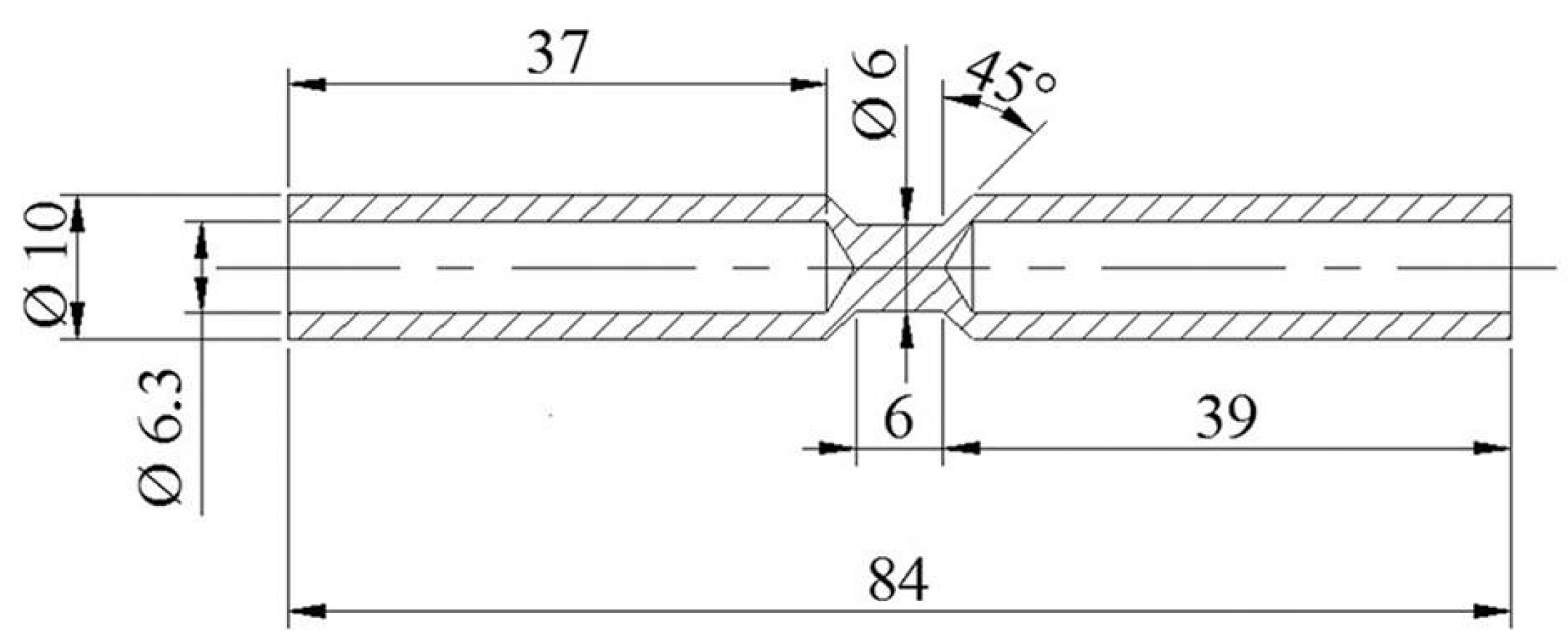
1 and Ms critical temperatures were determined by dilatometric analysis using a Gleeble 3800 thermo-mechanical simulator (Dynamic Systems Inc., Poestenkill, NY, USA), equipped with a ISO-Q Quenching and Deformation Dilatometer. The samples were heated at 1020 °C, with a heating rate of 300 °C/h, held for 1 h at the target temperature, and then cooled to room temperature using different cooling rates of 100 and 3000 °C/h. Volume variations of samples were measured by a laser dilatometry system [
13].
Figure 1 shows the geometry and dimensions of the samples used. Details of the experimental technique are reported elsewhere [
14].
The Gleeble
® 3800 simulator has also been used to reproduce single and double tempering treatments in the temperature range 610–700 °C using heating rates of 300 °C/h with holding times of 1 h followed by air cooling. Treated samples have been used to determine their mechanical properties. The volume fraction of retained austenite at room temperature (γ
r) was determined by X-ray diffraction (Philips, Eindhoven, The Netherlands). XRD spectra were collected in the 2θ angular range 5° to 65° by using the Mo-Kα radiation (
λ = 0.71 Å) in step scanning mode with steps of 0.05° and counting time of 5 s per step. The relative amounts of martensite and retained austenite were calculated for each sample from the integrated intensities of the reflections of both phases, following the ASTM E975 standard [
15].
Mechanical properties were measured by means of tensile tests on a Galdabini
® SUN 1000 tensile machine (Cardano al Campo (VA), Italy). Tensile specimens which were 1 mm in thickness, 12.5 mm in width, and with a gage length of 50 mm, heat treated by Gleeble 3800 as described above have been used. Tests were performed using a crosshead displacement rate of 1 mm/s, and the gage length elongation was measured using an extensometer. To compare the quantity of austenite in the microstructure of samples subjected to different quenching and tempering treatments, the instantaneous strain-hardening coefficient (
n) was evaluated. It is defined as follows:
where
σ and
ε are true stress and true strain, respectively.
The presence of the austenitic phase—with its associated high work hardening behavior—induces high
n values and pronounced plateau in the
n vs. true strain curves, depending on its volume fraction and stability. Moreover, it is also responsible for the observed marked serration in the instantaneous strain hardening curves [
16].
Microstructural studies have been carried out by transmission electron microscopy (TEM) using a Philips® CM12 microscope (Philips Electron Optics, Eindhoven, The Netherlands) equipped with a Bruker® Quantax TEM 200T EDX system (Bruker, Berlin, Germany). Thin foils were prepared by mechanical grinding followed by double-jet electropolishing in a solution of 10% perchloric acid and 90% butoxyethanol at 258 K (−15 °C) and 9 V.
Alloy hardness was measured using Rockwell (Hardness tester, C.I.S.A.M. sas, Induno Olona, Italy) tests from industrial byproducts and Vickers (Micro-hardness tester, Shimadzu Corporation, Kyoto, Japan) tests from 1 mm-thick heat-treated samples used in the Gleeble 3800 simulator. The Vickers hardness scale is frequently used for these heats for weld procedure qualification tests, and according to the BS860 1967 standard, a 23 HRC limit would be equivalent to 253 HV. It has been shown that this conversion—as well as the ASTM E140-88 correlation—is not applicable to 13Cr-4Ni-(Mo) materials, with several researchers indicating 23 HRC as equivalent to 275 HV [
17,
18]. Therefore, this hardness equivalence will be used hereinafter.
3. Results
Table 2 compares the hardness values of preliminary hot forged (HR) and as-quenched (after forging) (OQ) samples from different heats. In spite of their similar chemical compositions, hot rolled samples are very different in hardness, with Heat A (31.1 ± 1.0 HRC) being significantly harder than Heat B (25.1 ± 0.8 HRC).
The hardness difference was partially recovered in OQ samples where Heat B (34.2 ± 1.2 HRC) showed about the same hardness as Heat A (35.3 ± 1.3 HRC). Considering that the hardness value is also affected by the amount of retained austenite, the Ms–Mf range for Heat A is expected to be higher in temperature than for Heat B.
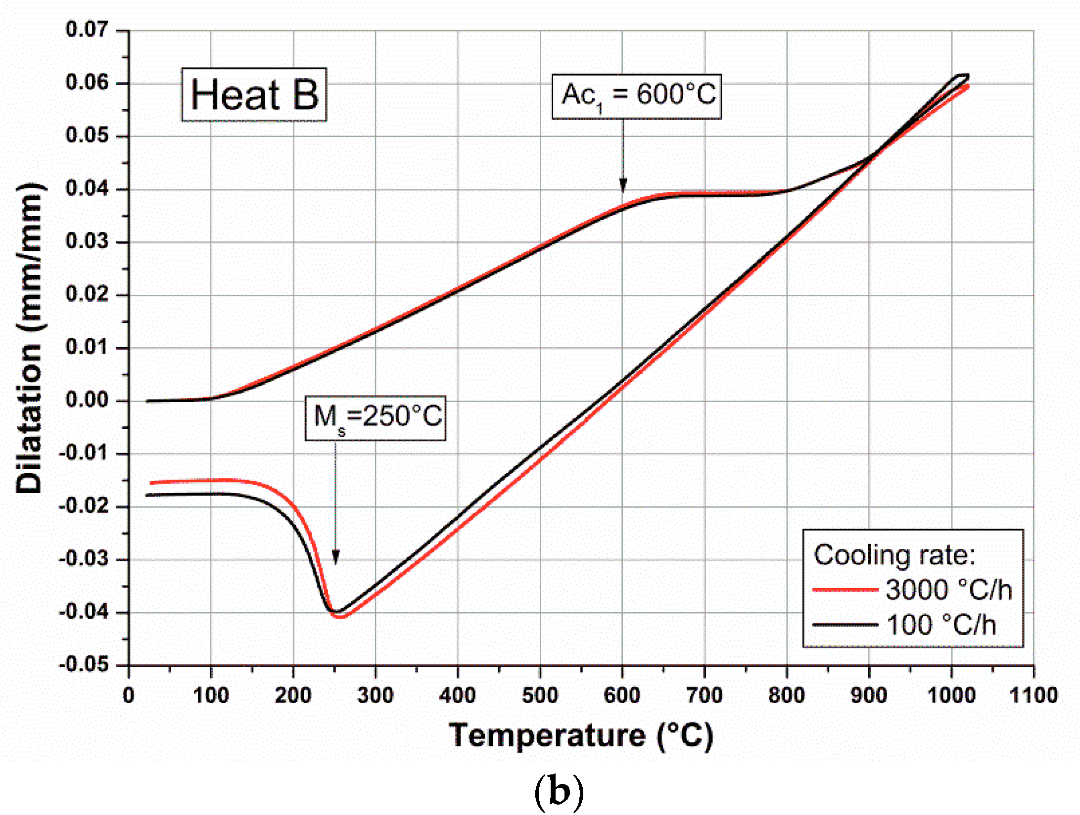
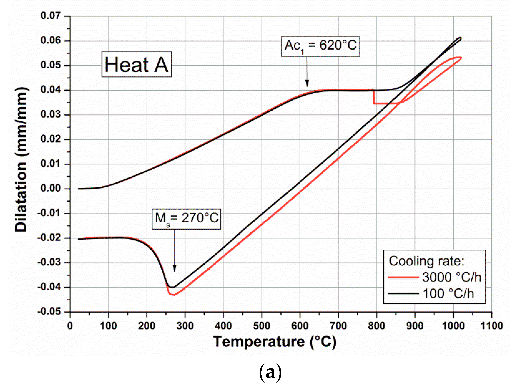
The Ms and Ac
1 critical temperatures have been determined through dilatometric analysis, and relevant experimental curves for Heat A and Heat B are reported in
Figure 2.
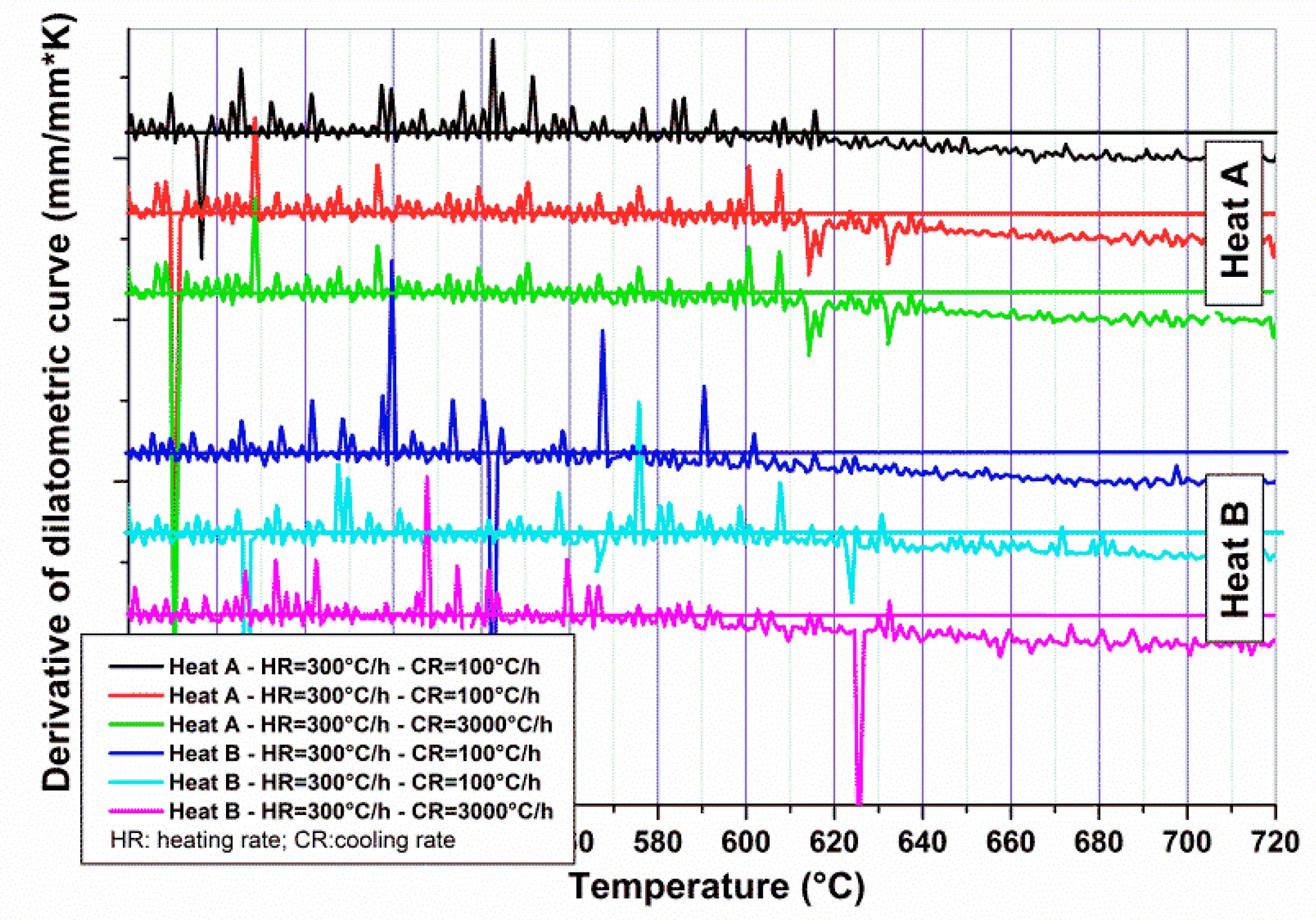
The experimental Ac
1 temperatures for Heats A and B were calculated from the dilatometric curves and by analyzing their derivatives.
Figure 3 shows the derivative curves in the range of temperature close to the transformation point. Three different curves have been considered, performed at different cooling rates (two samples at 100 °C/h and one at 3000 °C/h), but with the same heating rate (300 °C/h). For the same Heat, there is a good agreement among the Ac
1 temperatures determined from different samples. The uncertainty of calculated Ac
1 was determined using the temperature range in which it is possible to verify the slope change of dilatometric curves and their derivatives.
Ac
1 temperatures for Heat A and B were around 620 ± 10 and 600 ± 10 °C, respectively. These results could be compared to the calculated Ac
1 temperature for 13% Cr steels having carbon contents lower than 0.05% [
19], according to the following formula:
The predicted Ac1 temperature for Heats A and B were 647 and 633 °C, respectively. These values are higher than the experimental temperature, although it is confirmed that the Ac1 temperature of Heat A is higher with respect to Heat B.
The Ms temperature for Heat B (250 ± 10 °C) is lower than Heat A (270 ± 15 °C), thus supporting the propensity for this alloy to retain higher volume fractions of austenite in HR and OQ products.
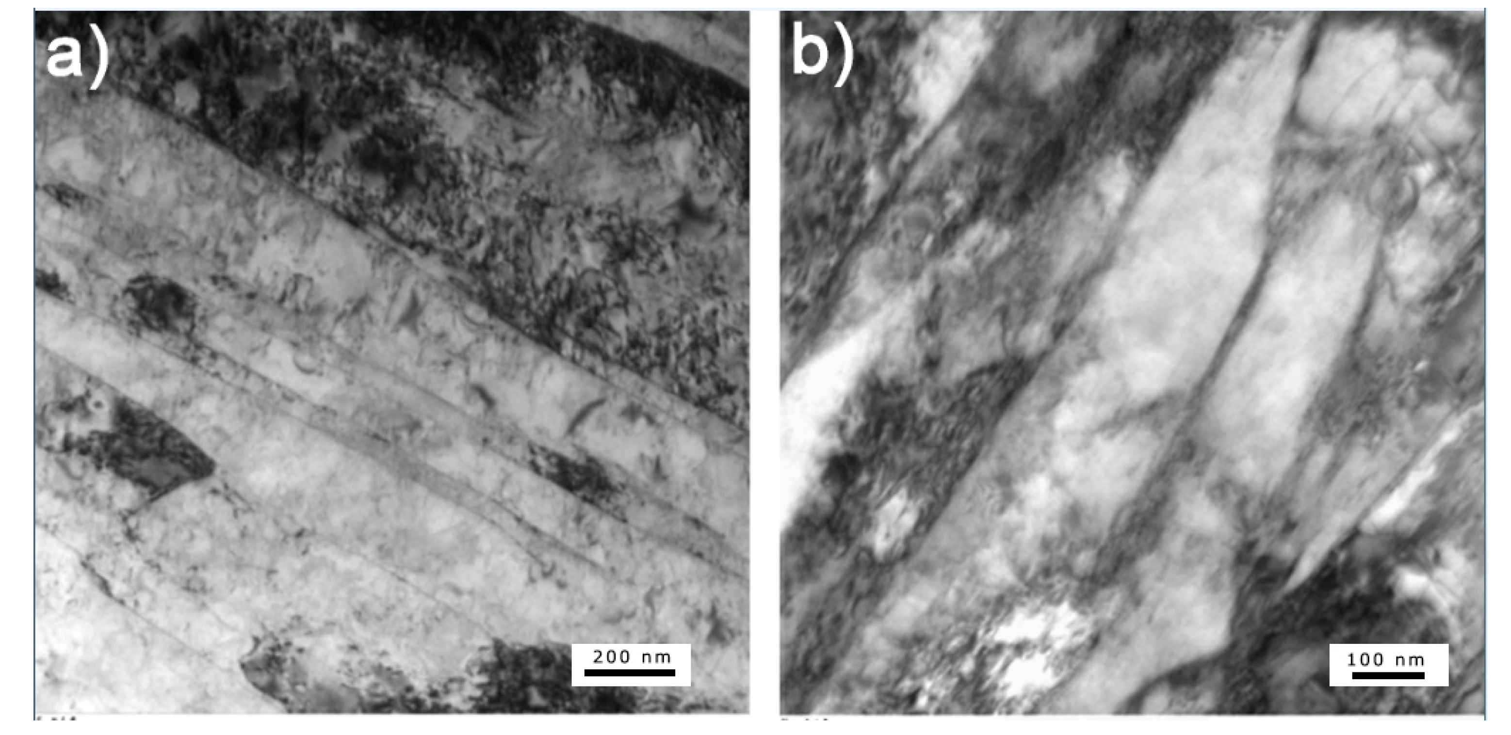
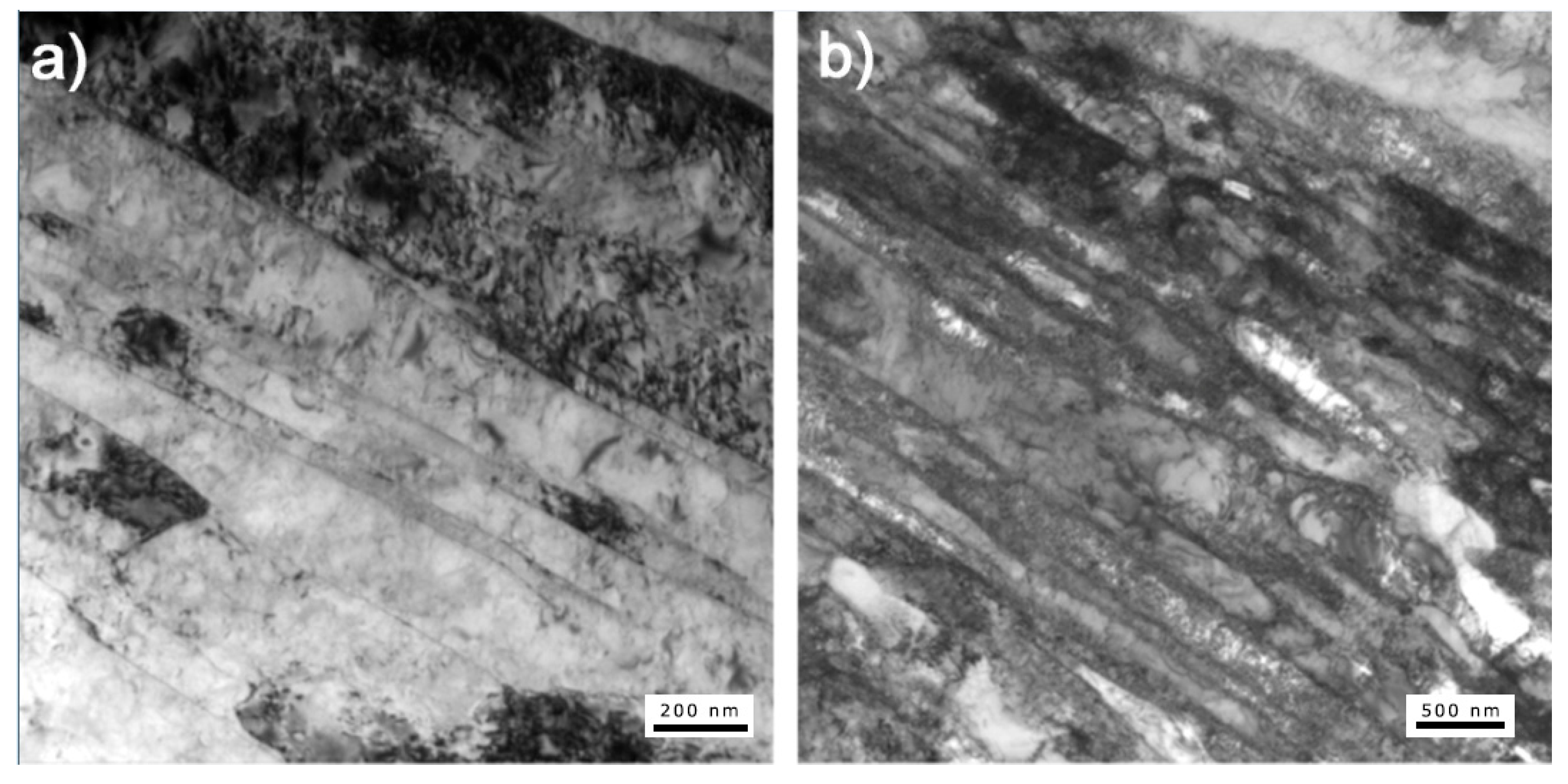
Figure 4 shows electron micrographs from OQ samples of Heat A and Heat B. The microstructures consist of an α’ martensite matrix, in which fine and highly dislocated laths are distributed parallel to one another. The presence of retained austenite is not evident in OQ state, being scarcely visible only in Heat B in the form of thin interlath films (
Figure 4b).
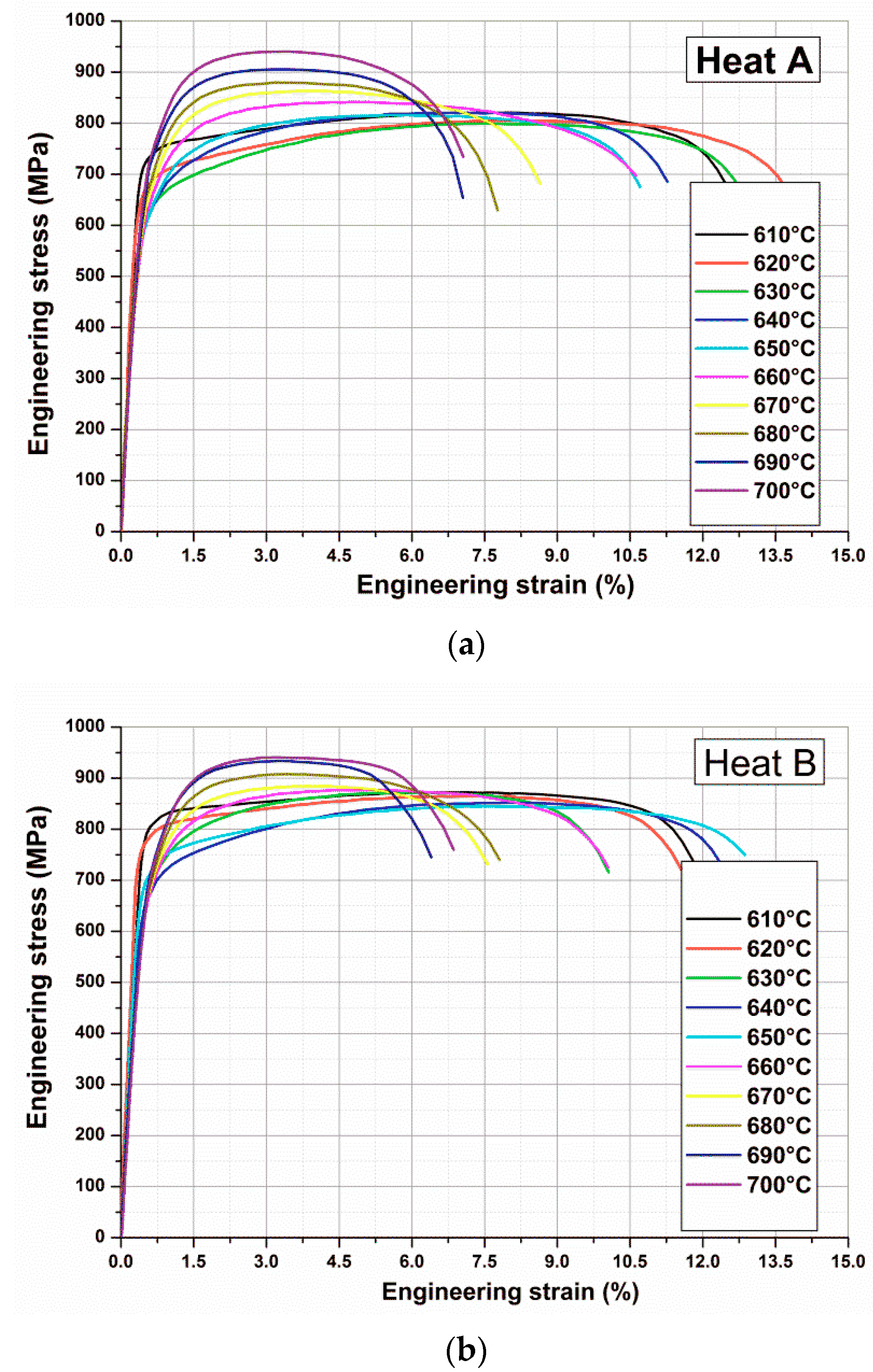
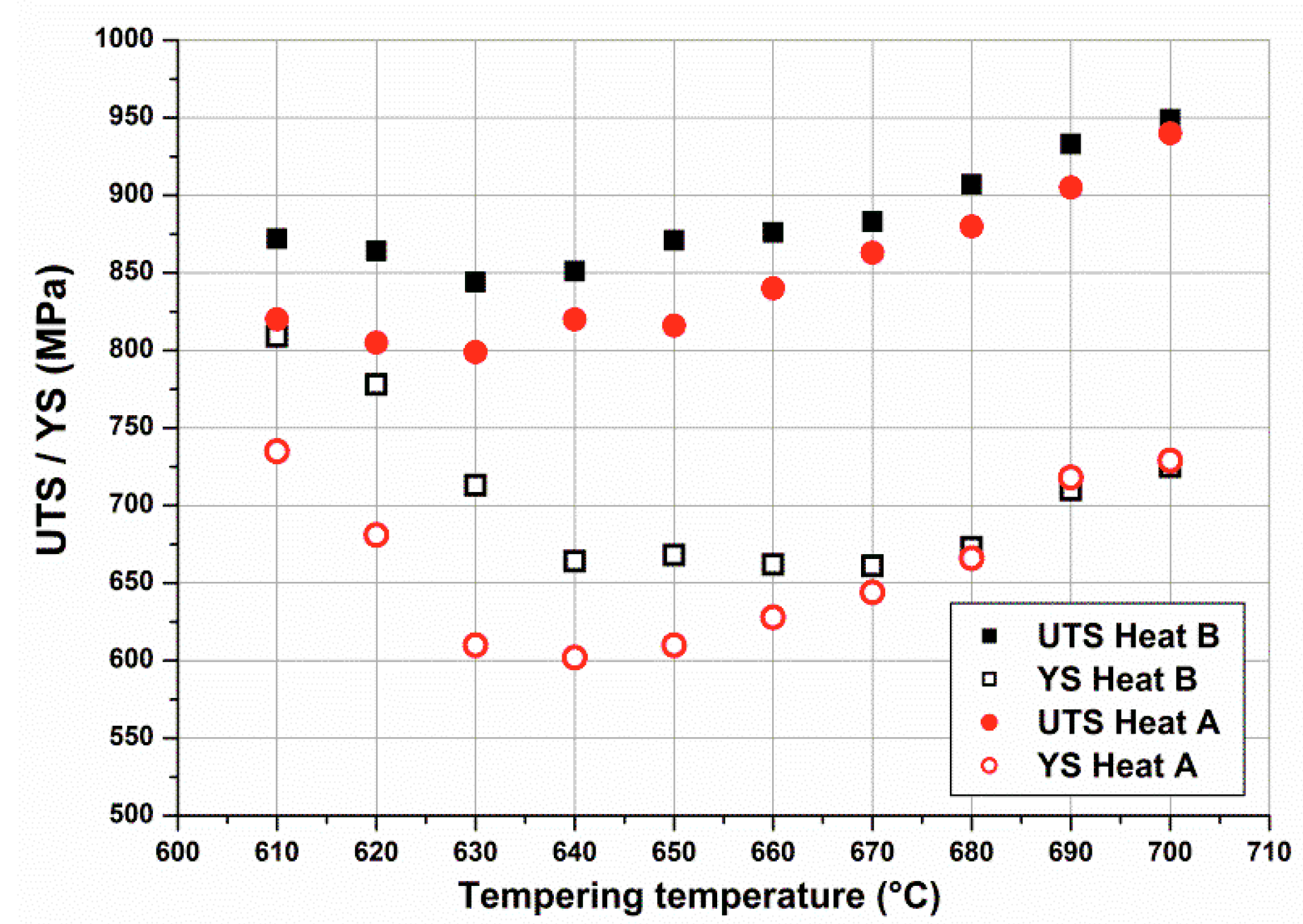
Figure 5 shows stress–strain curves and
Figure 6 yield strength (YS) and ultimate tensile strength (UTS) values obtained on OQ samples heat treated (tempered) by Gleeble 3800 for one hour at different temperatures in the temperature range 610–700 °C.
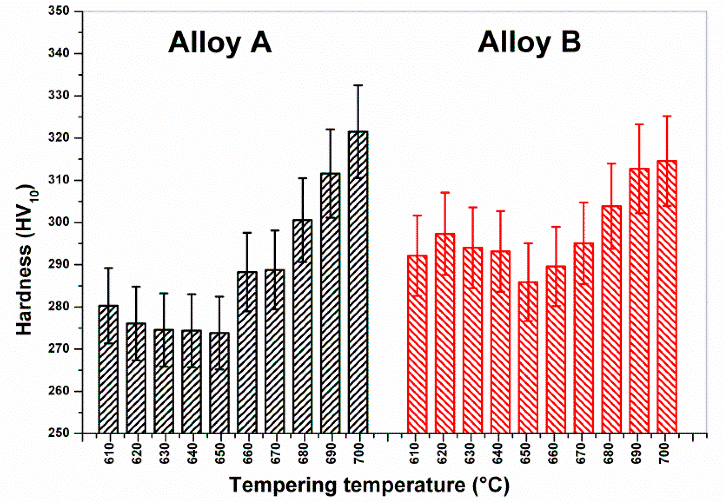
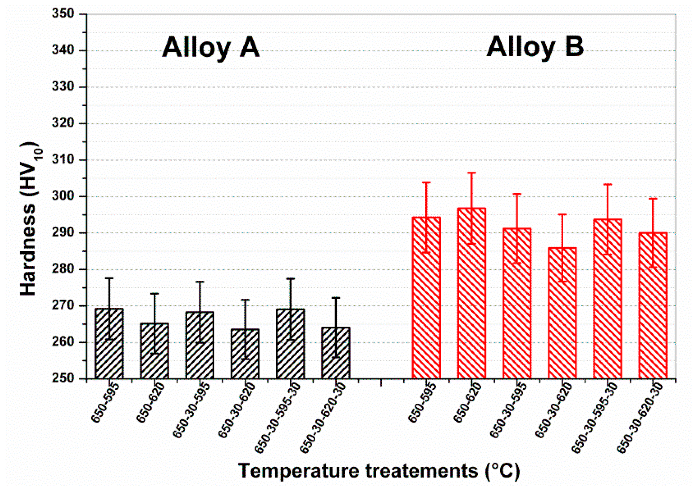
The Vickers hardness (HV10) measurements of these samples are shown in
Figure 7. It can be observed that Heat B remained constantly harder than the limit of 275 HV (23 HRC), whereas the hardness reduction of Heat A allowed values close to the limit. Moreover, for both heats there was a slight decrease of strengths and hardness when increasing the tempering temperature from 610 to around 650 °C, followed by a step increase for higher temperatures.
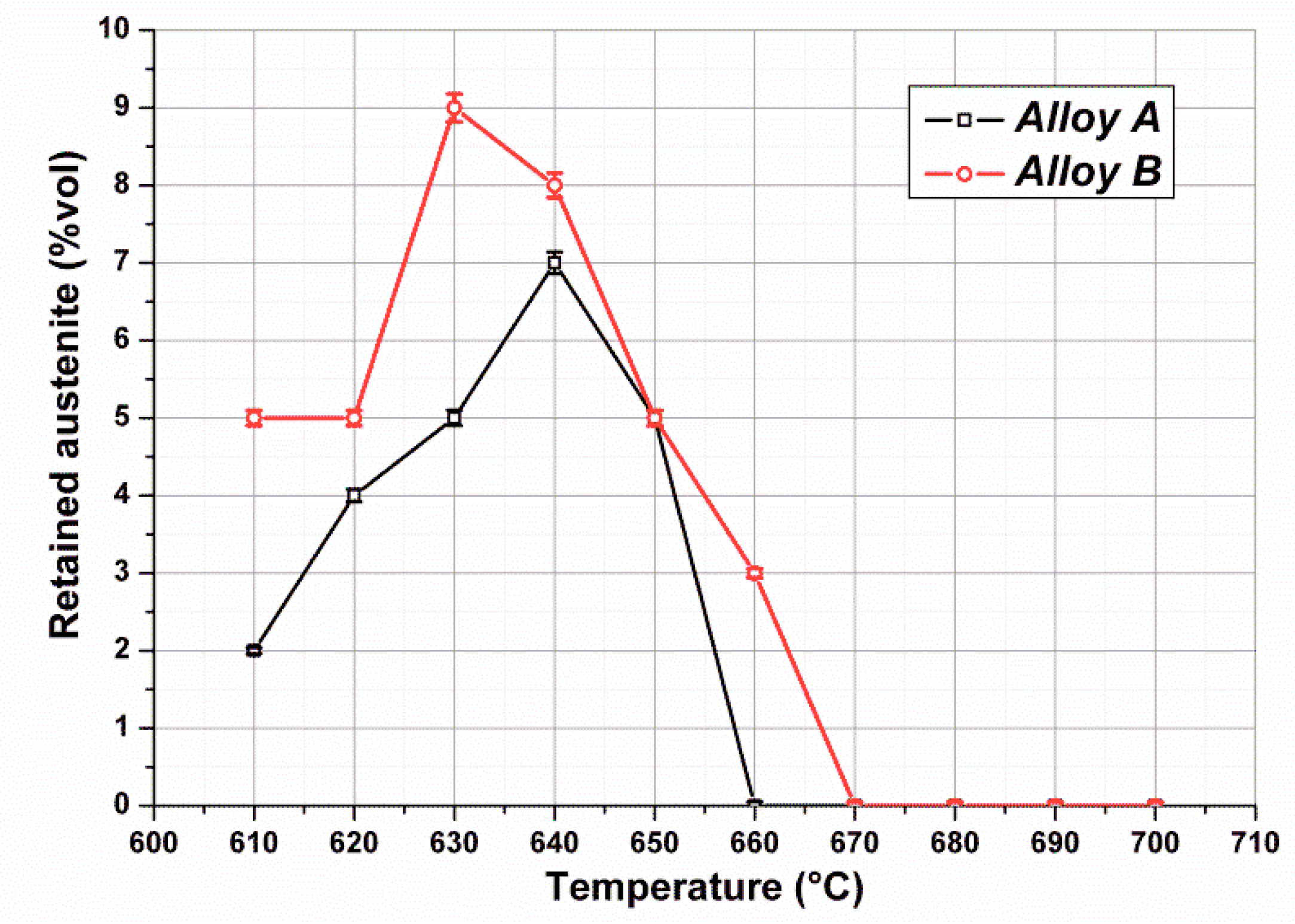
Figure 8 shows volume fractions of retained austenite measured in Heat A and Heat B after single tempering. The austenite content of both heats was relatively low, with the values consistently below 10%. For Heat B the peak was reached at 630 °C, whereas for Heat A it was around 640 °C.
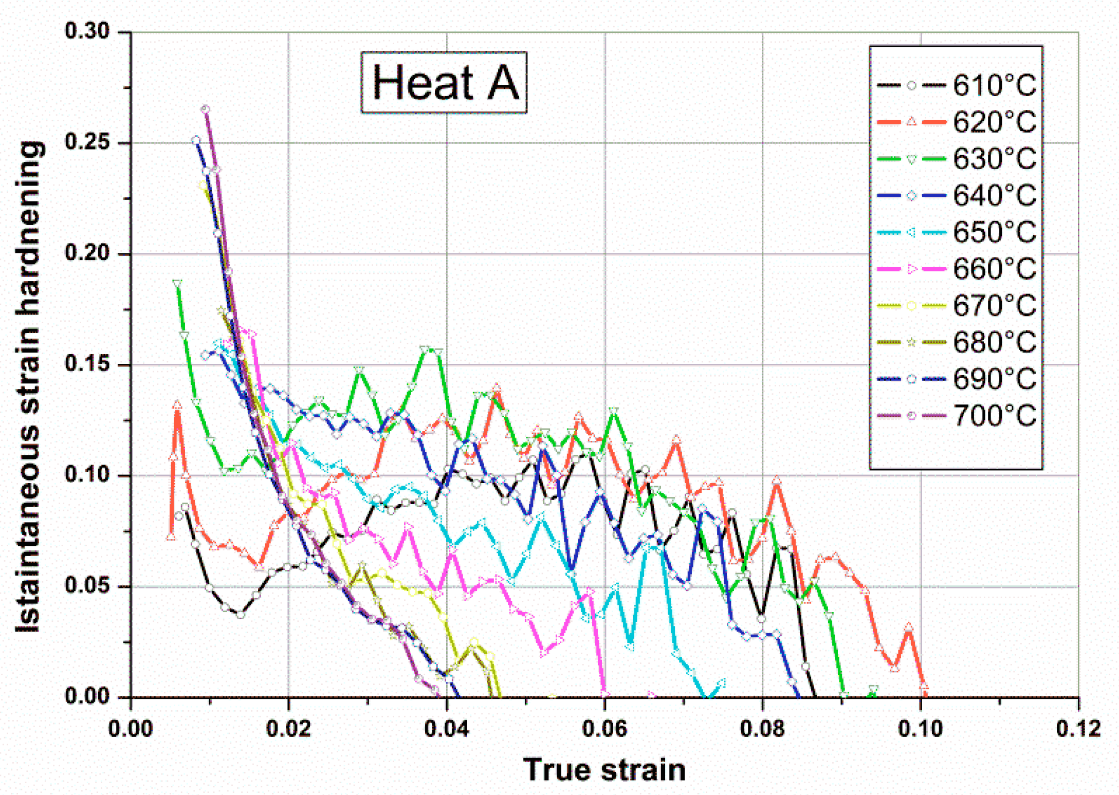
Strength and hardness were reduced in the presence of retained austenite, but they showed a further increase when austenite disappeared, as shown in
Figure 6. This was also confirmed by the instantaneous strain hardening coefficient,
n, measured during tensile tests of single tempered samples, as shown in
Figure 9. This coefficient is sensitive to all factors influencing the strain hardening behavior of the steel. For steels whose microstructure is a mixture of martensite and austenite, both the mean value and the punctual variability of
n were affected by relative amounts of soft retained austenite. As shown in
Figure 9, the gradual loss of stability of reverted austenite for tempering temperatures above 640 °C in Heat A is apparent, with a practical absence of retained austenite at room temperature for tempering treatments above 670 °C.
From these results, the final hardness after single tempering appears to be the result of both the structural recovery of untempered martensite and the relative stability of reverted austenite during previous heating. Strength and hardness initially decreased after single tempering above 600 °C due to increased recovery of as-quenched martensite and the retention of stable retained austenite. For increasing temperatures, reverted austenite became unstable, forming virgin martensite upon cooling, thus determining a further increase of both hardness and strength.
Figure 10 shows the microstructure of Heat A after single tempering at 620 °C (
Figure 10a) and 680 °C (
Figure 10b), respectively, below and above the critical temperature for austenite destabilization upon cooling. The microstructure of samples tempered at 620 °C consisted of tempered martensite with elongated islands of retained austenite formed in the interlath regions with no evidence of untempered martensite. After tempering at 680 °C, many islands of highly dislocated virgin martensite were observed.
Finally,
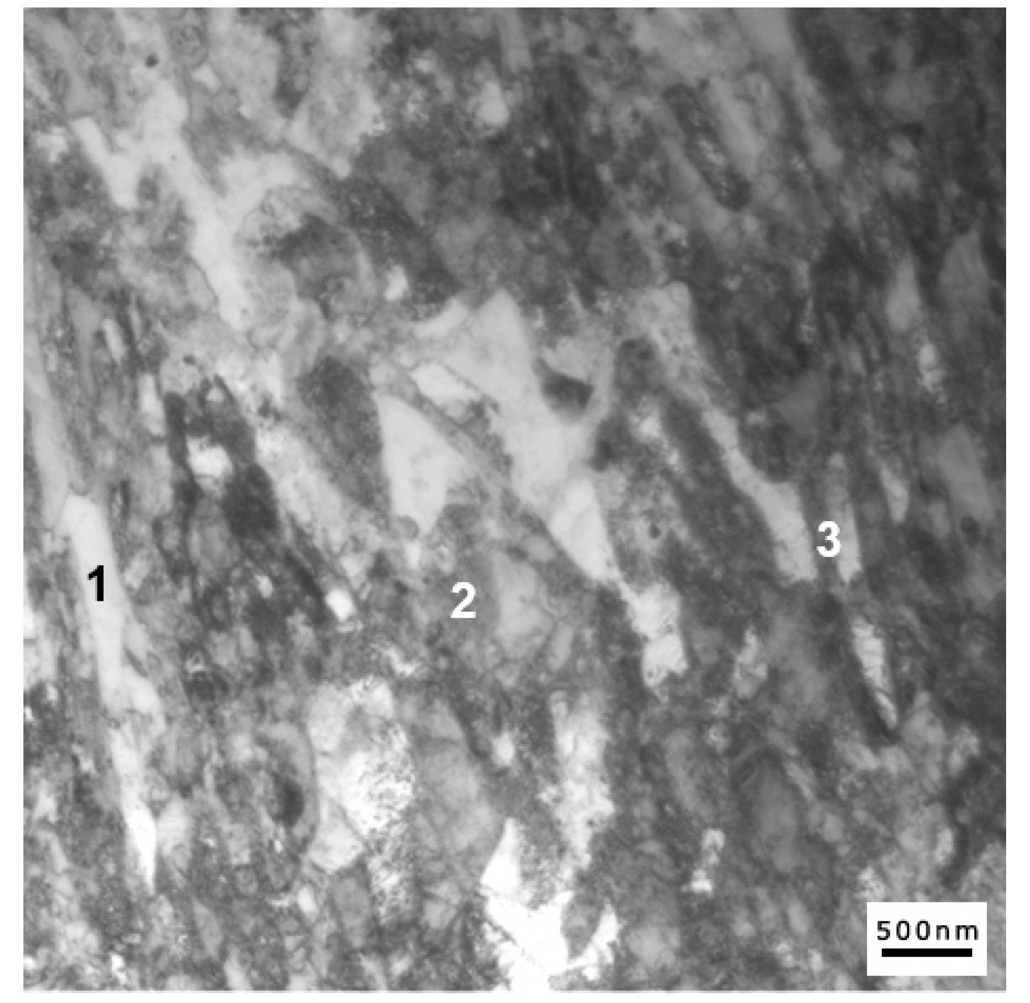
Figure 11 shows the alloy microstructure after tempering at 650 °C, where all possible structural constituents may coexist—specifically, recovered original martensite, virgin martensite, and retained stable austenite.
As shown in
Figure 11 and
Table 3, image contrast coupled with energy-dispersive X-ray spectroscopy (EDS) measurements can be conveniently used to distinguish between different constituents. Regions where α’ to γ reversion occurred are characterized by an increased amount of both Ni and Mn compared to the nominal heat composition, as a consequence of solute redistribution between phase constituents during tempering.
Among these areas, retained austenite islands can be further distinguished by a low density of dislocations (
Figure 11, Region 1), in contrast to virgin martensite with a high density of dislocations (
Figure 11, Region 3). Finally, regions of tempered martensite are characterized by decreased nickel content compared to the nominal heat composition, as well as by partial recovery of the martensitic matrix (
Figure 11, Region 2).
The effect of a second tempering treatment was investigated, taking into consideration NACE recommendations for the first cycle (for which NACE requires a temperature in the range 648–690 °C); two temperatures corresponding to the presence or total absence of stable austenite were chosen: 650 °C (
P = 18.4) and 680 °C (
P = 19.0), respectively. For the second cycle, the minimum and maximum NACE-recommended temperatures—595 °C (
P = 17.3) and 620 °C (
P = 17.9)—were used.
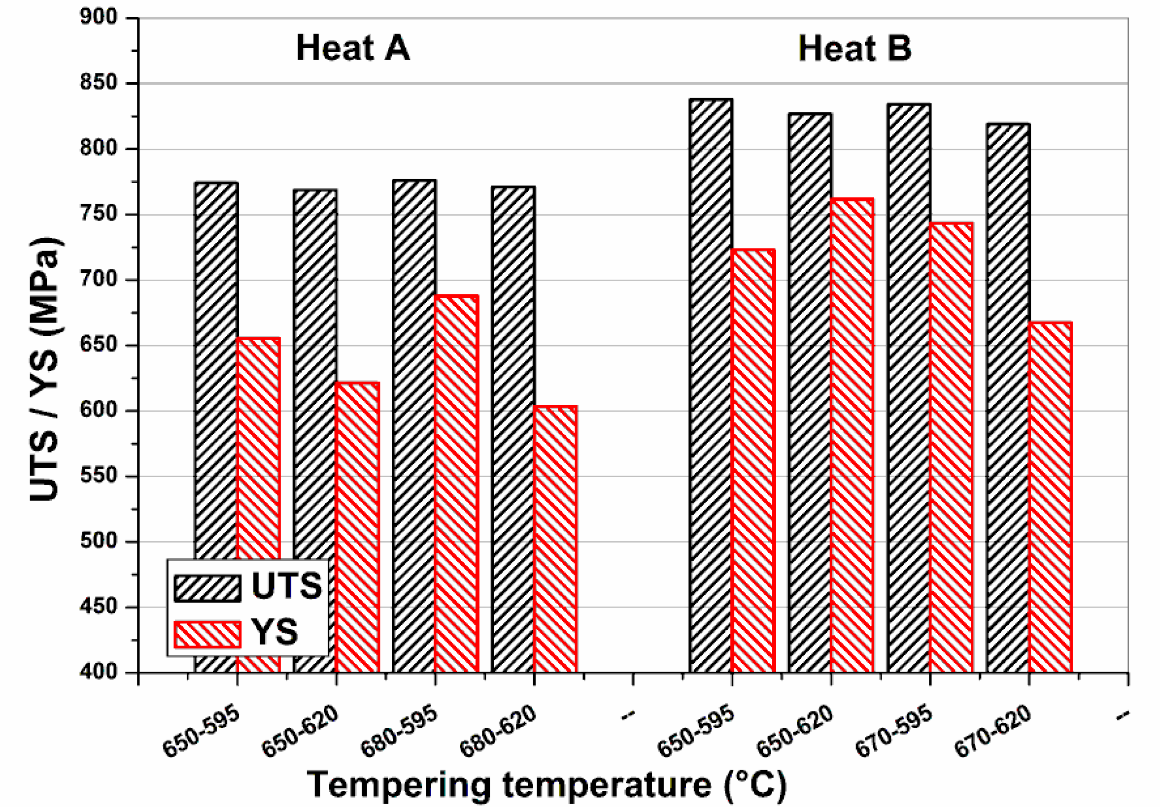
Figure 12 shows YS and UTS, and
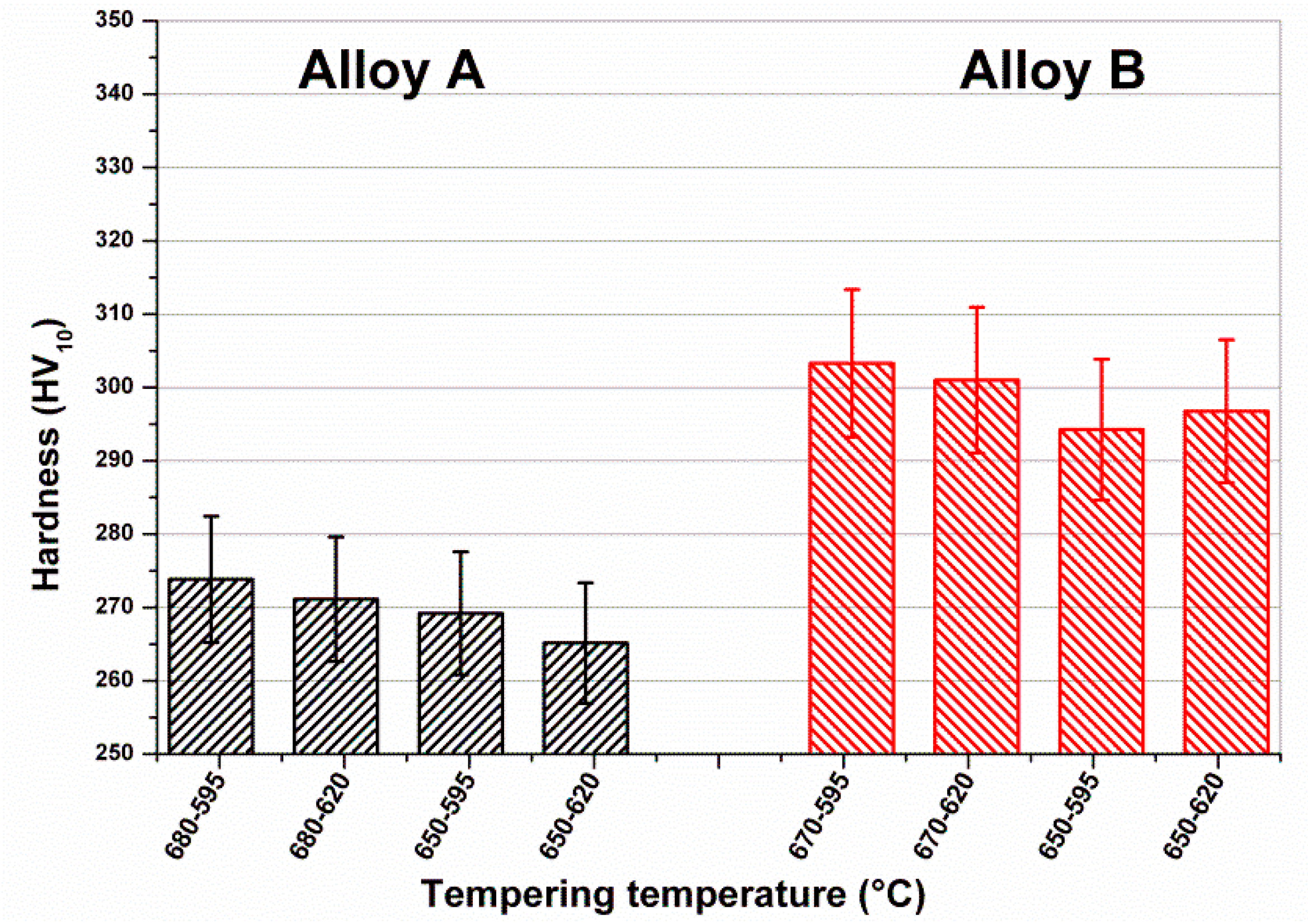
Figure 13 shows the hardness after double tempering.
Both tensile strength and hardness levels were significantly lower compared to the first tempering cycle, with hardness reduced to 266 HV after 1 h at 650 °C, and 1 h at 620 °C, whereas no useful reductions were obtained for Heat B, with tensile strengths above 800 MPa, with hardness values remaining around 300 HV10.
The effects of intermediate and final sub-zero cooling (−30 °C) for double tempering treatment were studied using 650 °C for the first tempering temperature and varying the temperature of the second cycle from 595 to 620 °C. The results reported in
Figure 13 indicate that an intermediate cooling between the first and the second temper was beneficial for the reduction of hardness, especially for Heat B, thus confirming Gooch’s suggestions [
12].
Moreover, a final sub-zero treatment—which is expected to partially destabilize retained austenite—induced an increase in hardness, especially for Heat B (as shown in
Figure 14).
4. Discussion
Despite similar chemical compositions and almost similar Creq/Nieq ratios of Heats A and B, their responses to heat treatments were rather different. It is apparent that a significant reduction of hardness below the NACE limit (23 HRC) could be accomplished only for Heat A, whereas Heat B remained hard while also adopting the double tempering strategy recommended by NACE standards.
In order to obtain significant hardness reductions after tempering, the as-quenched martensite matrix should recover at high temperatures, allowing the retention of soft austenite islands without destabilization to virgin martensite. For the industrial heats studied, two major difficulties are presented. The first difficulty is to obtain significant volume fractions of stable retained austenite at room temperature, potentially as a result of the relatively high Ms values measured (
Figure 2). The second difficulty is an intrinsic instability of reversed austenite formed at a temperature that favors the transformation to virgin martensite during cooling and limits the hardness reduction after tempering in the final product.
The stability of reversed austenite decreased during tempering as consequence of solute partitioning of γ-stabilizer elements (especially Ni and C). As the tempering temperature increases, the volume fraction of reversed austenite increases and the consequent solute redistribution is no longer able to stabilize the γ phase on cooling. This aspect is believed to be critical for 13Cr-4Ni-(Mo) industrial heats, which are characterized by relatively low carbon and nickel contents as compared to other supermartensitic alloys [
6]. Moreover, alloying with molybdenum (0.5%) reduces carbon diffusion towards reverted austenite islands, thus further limiting stabilization of reverted austenite and lowering kinetics for martensite recovery. Molybdenum is effective in decreasing the diffusion coefficient of elements such as carbon and sulfur within ferritic/martensitic structures, because of its strong affinity for those elements [
20,
21]. Loveless et al. [
22] worked with 13Cr4Ni alloys, finding that variants containing molybdenum presented increasing difficulties for hardness reduction through tempering.
Additionally, it was observed that the retained austenite in these alloys was rather unstable. As demonstrated by the results reported in
Figure 14, there is an apparent destabilization effect of sub-zero cooling for Heat B. This aspect is believed to be important for mechanical components that work at low service temperatures and/or under manufacturing and service strains, since a loss in toughness and in corrosion resistance may be envisaged.
Under these circumstances, limiting the formation of reversed austenite is believed to be useful during tempering, and can be accomplished by increasing the Ac1 critical temperature of the alloy as much as possible. This consequently allows for the recovery of the as-quenched microstructure at higher temperatures without the detrimental effect of austenite destabilization and the formation of virgin martensite upon cooling.
For example, Heats A and B appear different for experimental Ac
1 and Ms temperatures, with both temperatures being higher for Heat A (Ac
1 = 620 °C, Ms = 270 °C) than for Heat B (Ac
1 = 600 °C, Ms = 250 °C). These differences might be the consequence of higher carbon and nitrogen contents for Alloy B, with nickel and manganese contents of alloys being almost identical (
Table 1). Therefore, more stringent control of carbon and nitrogen may be the key to controlling the final hardness of 13Cr-4Ni-(Mo) industrial heats.
A first attempt to verify these conclusions has been done with Heat C, reported in
Table 4.
The carbon content was reduced to 0.018% C, and the nitrogen content was reduced to 68 ppm. The predicted Ac1 temperature for Heat C is 670 °C, which is about 15 °C higher than Heat A. From this it would be possible to increase tempering temperature without the formation of large volume fractions of unstable reverted austenite. Heat C was treated through double tempering at 665 and 615 °C. The final mechanical properties—averaged from seven different samples—gave the following results: YS = 583 MPa, UTS = 751 MPa, with hardness of 21.4 HRC. These results allow for the supposition that the reduction of both carbon level below 0.02% C and nitrogen below 100 ppm are effective in controlling the final hardness of 13Cr-4Ni-(Mo) with industrial heats below NACE recommendations (23 HRC), without an unacceptable loss of mechanical strength.


