The Fabrication of All-Solid-State Lithium-Ion Batteries via Spark Plasma Sintering


1
Department of Mechanical Engineering, San Diego State University, 5500 Campanile Dr., San Diego, CA 92182, USA
2
Department of Nano Engineering, University of California, San Diego, 9500 Gilman Dr., La Jolla, CA 92037, USA
*
Author to whom correspondence should be addressed.
Metals 2017, 7(9), 372; https://doi.org/10.3390/met7090372
Submission received: 23 July 2017
/
Revised: 31 August 2017
/
Accepted: 11 September 2017
/
Published: 14 September 2017
(This article belongs to the Special Issue Powder Synthesis and Processing)
Abstract
:Spark plasma sintering (SPS) has been successfully used to produce all-solid-state lithium-ion batteries (ASSLibs). Both regular and functionally graded electrodes are implemented into novel three-layer and five-layer battery designs together with solid-state composite electrolyte. The electrical capacities and the conductivities of the SPS-processed ASSLibs are evaluated using the galvanostatic charge-discharge test. Experimental results have shown that, compared to the three-layer battery, the five-layer battery is able to improve energy and power densities. Scanning electron microscopy (SEM) is employed to examine the microstructures of the batteries especially at the electrode–electrolyte interfaces. It reveals that the functionally graded structure can eliminate the delamination effect at the electrode–electrolyte interface and, therefore, retains better performance.
1. Introduction
As the use of rechargeable electronic devices has expanded, the need for improvements in energy density, power capacity, and product safety has continued to rise. The traditional Li-ion batteries that are used in most devices have a liquid electrolyte solution because of the high ionic conductivity of these electrolytes. However, the use of liquid electrolytes has some disadvantages [1]. First, the electrolyte must be constrained from leaking out of the battery. This requires a relatively complex overall battery design and increases the amount of material needed for the battery. Second, the liquid portion of the battery is limiting the battery as part of the load bearing structure. Third, the liquid electrolytes are only operable within a narrow temperature range. The electrolyte will either freeze or boil if temperatures vary too much. All of these disadvantages result in batteries that are lacking in both reliability and safety.
Li-ion batteries with solid electrolyte are designed to solve above-mentioned issues because they do not need to contain any liquids. They can be integrated into the support of the overall product design because they have higher structural stability and they can be used in a much wider temperature range. However, current solid-state batteries have significantly lower power and energy densities than their liquid-state counterparts, making them less practical for industrial and commercial applications. Therefore, most of the studies regarding all-solid-state lithium-ion batteries (ASSLibs) are revolving around improving the power and energy densities of the cells.
Polymeric electrolytes were considered as they are easy to fabricate and flexible in some applications [2]. However, they have relatively low ionic conductivity and tend to oxidize when contacting electrodes [3]. Moreover, polymeric electrolytes are not stable at high temperature regimes.
Extensive research has been conducted on different ceramic materials for use as electrolytes, and three crystal structures have been shown to facilitate high total (bulk and grain boundary) ionic conductivity. Perovskite-structured electrolytes (Li3xLa2/3−xTiO3 or LLTO) have been found to have high ionic conductivity, which is comparable to that of liquid electrolytes [4,5,6,7]. However, this type of electrolyte also showed low redox potential vs. Li/Li+ [8]. Garnet-structured electrolytes such as Li7La3Zr2O12 (LLZO) have exhibited high ionic conductivity and stable electrochemical properties [9,10,11,12]. However, sintering temperature and the moisture resistance of LLZO should be taken into account [12,13,14,15,16]. Two commonly studied NASICON-structured electrolytes are LiTi2(PO4)3 (LTP) and LiGe2(PO4)3 (LGP). Both of them have shown high ionic conductivities [17,18]. Substituting Al for Ti in LTP forms Li1+xAlxTi2−x(PO4)3 (LATP). This doped composite has higher ionic conductivity, lower sintering temperature, and higher crystalline stability than the un-doped one [19,20,21] and is also stable against moisture [22,23].
The main drawback of the ceramic electrolyte materials is their high reactivity with electrode materials during heat treatment and reduction on contact with lithium [24]. If these electrolytes are to be used, appropriate electrodes need to be selected to avoid adverse reactions at the electrolyte–electrode interfaces during heat treatment, charging and discharging. The anode should have low potential, while the cathode should have high potential vs. Li/Li+, and neither of them should cause electrolyte decomposition. One optimal anode material is Li4Ti5O12 (LTO) with a potential of 1.55 V vs. Li/Li+ [25,26]; this material does not react with LATP electrolyte [27]. The most promising cathode materials are the olivine-structured compounds such as LiMPO4 (M = Fe, Mn, Ni, Co, etc.), providing high structural stability and low capacity loss [28]. Sintering techniques have been widely applied to produce ASSLibs including the most attractive spark plasma sintering (SPS) [8,29,30,31] thanks to its coupled electro-thermal mechanical features [32]. Aboulaich et al. successfully fabricated ASSLibs using composite electrodes [29,30]. However, the obtained cells showed low power density due to the small amount of active materials in the electrodes.
The present study aims at investigating the effect of regular and functionally graded electrodes on the power density and the interface quality of ASSLibs produced by the SPS technique. Electrodes with various concentrations of active materials were developed while focusing on increasing the power capacity. Keeping the same amount of composite ceramic electrolyte, three-layer and five-layer batteries were fabricated by consolidating electrode and electrolyte powders together in one SPS operation. The SPS-processed batteries were subjected to galvanostatic charge-discharge and electrical conductivity tests to determine the effect of electrode compositions on the relative energy and power density. Microstructural analyses were conducted to examine the electrolyte–electrode interfaces as the battery structure changed in correspondence to the evolution of its electrical properties.
2. Materials and Methods
Commercially available Li1.4Al0.4Ti1.6(PO4)3 powder (LATP, NEI Corp., Somerset, NJ, USA) was selected to build the electrolyte as it appears to be the most compatible one among all the ceramic electrolyte materials discussed in Section 1. In order to offset the thermal mismatch between electrolyte and electrode, LATP was also used in the electrodes. The active material in the anode was LTO (NEI Corp., Somerset, NJ, USA), while LiCoPO4 (LCP, NEI Corp., Somerset, NJ, USA) was added to the cathode, as both of these materials do not react with LATP [26,27]. To enhance the conductivity of ASSLibs, acetylene black (AB, MTI Corp., Richmond, CA, USA) powder was used as a part of the composite electrodes. The morphologies of all the employed raw powders were examined by SEM (Quanta 450, FEI Co., Hillsboro, OR, USA) and are shown in Figure 1. As one can see, these as-received powders have uniform particle size distribution with an average size in the nano range (different scales are used to properly exhibit the morphology). Additionally, the XRD analyses (X’Pert Pro, PAnalytical B.V., Almelo, The Netherlands) have confirmed that the raw powders are very close to their stoichiometry.
For the three-layer battery, as shown in Figure 2a, the regular electrodes consisted of 40 wt % LATP, 30 wt % active material (LTO or LCP), and 30 wt % acetylene black as they were able to be consolidated in one sintering operation according to Reference [33]. However, to create the functionally graded electrodes, different compositions were developed. A 60 wt % LATP, 10 wt % LTO, and 30 wt % acetylene black composition was implemented as a part of the functionally graded anode. One can see from Figure 2b that these secondary compositions served as an intermediate layer between the primary anode and the electrolyte, which had a higher LATP content, thereby reducing the difference in sintering temperature between the different layers. At the same time, on the cathode side, a layer of 20 wt % LATP, 50 wt % LCP, and 30 wt % acetylene black was primarily used to increase the energy density of the battery as it contained more active materials. These graded compositions were determined based on the analysis of the three-layer battery interface qualities (see details in Section 3).
Once the raw materials were characterized and the electrode compositions were determined, the next step was to create the composite powders. Selected powders were put together according to the predetermined weight percentages and ball-milled in a 95% ethanol solution at 60 RPM for 24 h. The ball milling was carried out in an 80 mL nylon jar with 1 mm tungsten carbide balls, and the weight ratio of balls to powder was set to 10:1. After the powders were homogenized, the mixture was placed on a hot plate and heated to 98 °C until the solvent evaporated. The remaining material was then brushed through a sieve to yield the composite electrode powders. The weighted electrode powder and electrolyte powder were loaded into 10 mm graphite tooling (I-85 graphite, Electrodes Inc., Santa Fe Springs, CA, USA). Graphite paper with a thickness of 0.15 mm (Fuji Electronic Industrial Co., Ltd., Kawasaki, Japan) was inserted between tooling components to make the ejection process after sintering simpler. All the battery layers were pressed down in the die and the entire tooling setup was pre-compacted at room temperature under 3 kN.
The SPS runs were conducted using Dr. Sinter SPSS-515 furnace (Fuji Electronic Industrial Co., Ltd., Kawasaki, Japan) with a pulse duration of 3.3 ms and on/off pulse intervals of 12:2. The maximum processing temperature during the SPS process ranged from 650 to 850 °C with the holding time spanned from 5 to 30 min. The heating rate was set to 100 °C/min. An axial pressure of 45–60 MPa was applied at the start of heating and held consistently until the end of each experiment. During each SPS process, a K-type thermal couple was used to monitor the temperature evolution at the graphite die. All the real-time processing parameters were automatically logged by the device. Every individual experiment was repeated at least twice to ensure the reproducibility of the results.
To test the electrical properties of the obtained batteries, a galvanostatic charge–discharge tester (PGSTAT204, Metrohm Autolab B.V., Utrecht, The Netherlands) was first used to evaluate the electrical capacity. In these tests, the cells were charged and discharged with a constant rate of 20 μA/cm2. For both three-layer and five-layer batteries, the charge time was 60 min, and the tests were conducted until the batteries were fully discharged, as shown by a drop-off in cell potential. The energy and the power density of the cells were compared by examining the achieved potential level for the total charge-discharge cycle and the specific capacities at given period of time for each battery. The electrical conductivities of the batteries were evaluated by a digital multimeter (HDM4100, Commercial Electric Inc., Taiwan) after the batteries have been discharged. The resistivity, , and the conductivity, , were calculated using Equation (1), where l is the length of the battery in cm, A is the cross-sectional area of the battery in cm2, and R is the measured resistance in ohms. In order to properly conduct these electrical tests, two thin tin plates were fabricated to clamp onto both ends of the batteries serving as current collectors.
After the electrical tests, the obtained batteries were cut into halves on a precision diamond saw (IsoMet 1000, Buehler, Lake Bluff, IL, USA) to have their cross sections exposed. The samples were then ground and polished using SiC grinding papers with increasing grit size on an automatic polishing machine (TegraPol-11, Struers Inc., Cleveland, OH, USA). Once the samples were well polished, they were examined using SEM for microstructure observation.
3. Results and Discussion
The completeness of the batteries’ consolidation under various SPS conditions is indicated in Table 1. One can see that the batteries processed at 825 °C under an 80 MPa pressure with a 30 min holding time delivered the highest densification level and the best joining interface between electrodes and electrolyte. The others either had no fully consolidated electrodes or contained nearly melted components, although the electrolyte was always consolidated. Therefore, the above-mentioned processing parameters were considered to be the most efficient under the studied SPS processing regimes and the comparison between the regular three-layer and the functionally graded five-layer batteries was mainly conducted for the specimens processed by applying these conditions.
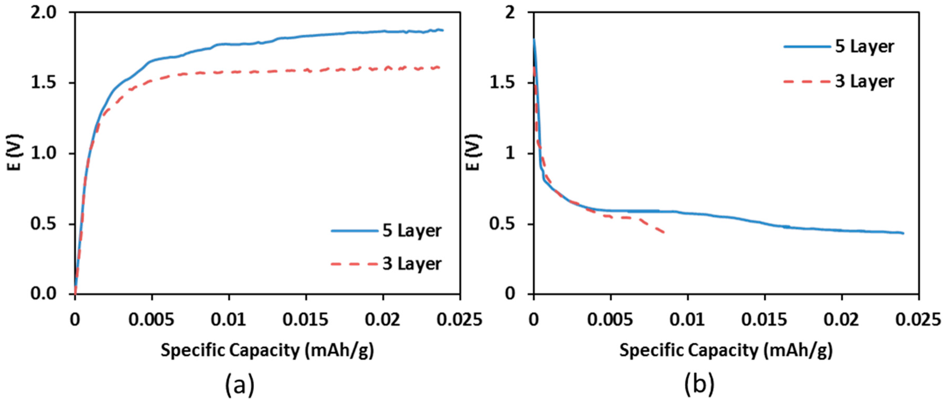
The galvanostatic charge–discharge tests determined whether or not the implementation of the functionally graded electrodes improved the electrochemical performance of the batteries. Figure 3 shows the results of these tests. The average charge potential of the five-layer battery is higher than that of the three-layer one (Figure 3a), resulting in an increase in the discharge capacity and the average discharge potential in the five-layer battery (Figure 3b). This observation indicates that both the energy density and power density of the cell was improved by implementing the functionally graded electrodes. However, it is important to note that both of the batteries produced in this study show significantly lower specific capacities than the battery constructed in Reference [34]. There are a number of possible reasons for this: (i) the materials used for battery components; (ii) possible contamination of battery materials during preparation (ball milling, baking, etc.), reducing their abilities to conduct lithium ions; (iii) different battery dimensions (i.e., electrode and electrolyte thicknesses). The main conclusions to draw from this test are (i) the implementation of functionally graded electrodes improves both the energy and power densities of ASSLibs; (ii) these fabrication techniques used in the present study can be generally transferred to the production of other types of ASSLibs with achieving high capacities.
Table 2 shows the resistivity and conductivities of both three- and five-layer batteries. The conductivities of their constituent powders are also included as a reference (note that the conductivity of acetylene black was provided in the material manufacturer data sheet). As one can see, the resistivity of the battery with functionally graded electrodes is lower than that of the battery without. This is most likely due to the reduced delamination at the anode–electrolyte interface that comes from the introduction of the functionally graded electrodes. It is worth noting that, although the LATP powder owns the highest conductivity, the conductivities of the fabricated batteries are limited by those of their constituent materials. In addition, the existence of interfacial imperfections between electrodes and electrolyte also appears to be a factor lowering the conductivity. As a result, the conductivities of both batteries are lower compared to the raw materials, but they are still within the expected range based on the literature. Since the resistances of the ASSLibs were measured with a digital multimeter, the diffusion resistance was not taken into account. To have more accurate measurements, it is better to apply AC impedance method to separate the intrinsic resistances.
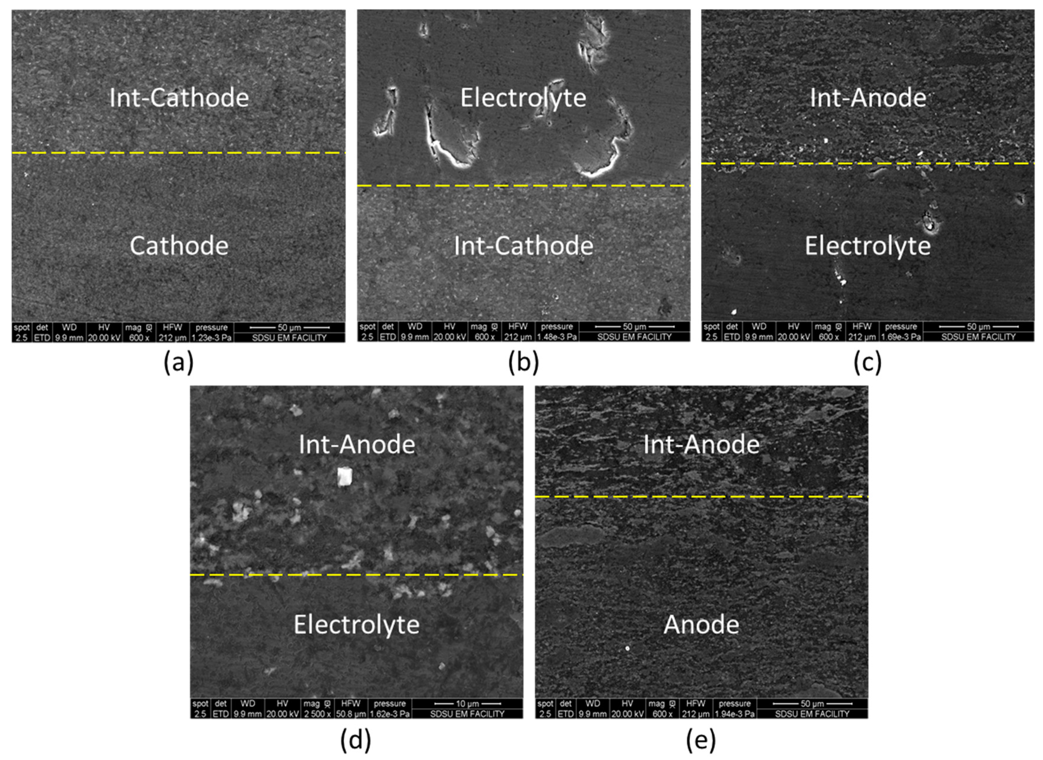
Figure 4 shows the micrographs of the electrode–electrolyte interfaces in the three-layer battery. It shows that the cathode–electrolyte interface has no evidence of delamination, while the anode–electrolyte interface does. The delamination was not complete, so the battery was able to remain intact, but as mentioned previously, the presence of delamination at the electrode–electrolyte interface is a major contributor to interfacial resistance. The manner in which the functionally graded electrodes were constructed was determined based on these images. It was clear that the original cathode composition and electrolyte consolidated well (see Figure 4a), meaning that this composition could be used as the intermediate cathode layer and a new composition with a higher concentration of LCP could be used as the primary cathode. However, the cracking seen at the anode–electrolyte interface is indicative of thermal mismatch (see Figure 4c). Therefore, a new anode composite with a higher concentration of LATP needed to be implemented as an intermediate layer between the electrolyte and the original composite anode.
Figure 5 shows the SEM images of the various interfaces in the functionally graded five-layer battery. One can see that the interfaces on the cathode side of the battery still exhibit no signs of delamination or cracking (see Figure 5a,b). Moreover, the introduction of the intermediate anode layer eliminated the cracking that occurred at the anode side as in the three-layer battery (see Figure 5c–e). These images indicate that introducing functionally graded electrodes can improve the interface quality of ASSLibs and the power density accordingly. The comparison between Figure 4 and Figure 5 also shows that the implementation of the functionally graded electrodes enhances the structural integrity of the fabricated ASSLib, so the five-layer battery retains better performance.
4. Conclusions
The ability of SPS to fabricate functionally graded components of all-solid-state Lithium-ion batteries has been investigated in the present study. Two types of ASSLibs have been successfully produced and tested. The first one employed the traditional design with regular electrodes. The second employed a novel design implementing functionally graded electrodes. The second design allowed the battery to maintain high-quality interfaces between each component and to contain a more active electrode material. The electrical properties and the microstructures of the SPS-processed batteries were evaluated comparatively. It was shown that the functionally graded electrodes were able to eliminate the delamination at the component interfaces and to result in higher energy and power densities. Both theoretical and experimental advantages of this novel battery design have been validated. The obtained results are of importance for tailoring and optimizing ASSLibs via SPS technique.
Acknowledgments
The support of the U.S. Department of Energy, Materials Sciences Division, under Award No. DE-SC0008581 is gratefully acknowledged. The authors also acknowledge the assistance of Steve Barlow, and the use of SEM equipment at the San Diego State University Electron Microscopy Facility acquired by NSF instrumentation grant DBI-0959908.
Author Contributions
Xialu Wei, Jack Rechtin, and Eugene A. Olevsky conceived and designed the experiments; Jack Rechtin performed the experiments; Xialu Wei, Jack Rechtin, and Eugene A. Olevsky analyzed the data; Xialu Wei and Jack Rechtin wrote the paper.
Conflicts of Interest
The authors declare no conflict of interest.
References
- Thangadurai, V.; Weppner, W. Li6ALa2Ta2O12 (A = Sr, Ba): Novel garnet-like oxides for fast lithium ion conduction. Adv. Funct. Mater. 2005, 15, 107–112. [Google Scholar] [CrossRef]
- Fergus, J.W. Ceramic and polymeric solid electrolytes for lithium-ion batteries. J. Power Sources 2010, 195, 4554–4569. [Google Scholar] [CrossRef]
- Kali, R.; Mukhopadhyay, A. Spark plasma sintered/synthesized dense and nanostructured materials for solid-state Li-ion batteries: Overview and perspective. J. Power Sources 2014, 247, 920–931. [Google Scholar] [CrossRef]
- Inaguma, Y.; Chen, L.Q.; Itoh, M.; Nakamura, T.; Uchida, T.; Ikuta, H.; Wakihara, M. High Ionic-Conductivity in Lithium Lanthanum Titanate. Solid State Commun. 1993, 86, 689–693. [Google Scholar] [CrossRef]
- Inaguma, Y.; Chen, L.Q.; Itoh, M.; Nakamura, T. Candidate Compounds with Perovskite Structure for High Lithium Ionic-Conductivity. Solid State Ion. 1994, 70, 196–202. [Google Scholar] [CrossRef]
- Ling, M.E.; Zhu, X.H.; Jiang, Y.; Zhu, J.L. Comparative study of solid-state reaction and sol-gel process for synthesis of Zr-doped Li0.5La0.5TiO3 solid electrolytes. Ionics 2016, 22, 2151–2156. [Google Scholar] [CrossRef]
- Mei, A.; Wang, X.L.; Lan, J.L.; Feng, Y.C.; Geng, H.X.; Lin, Y.H.; Nan, C.W. Role of amorphous boundary layer in enhancing ionic conductivity of lithium-lanthanum-titanate electrolyte. Electrochim. Acta 2010, 55, 2958–2963. [Google Scholar] [CrossRef]
- Baek, S.W.; Lee, J.M.; Kim, T.Y.; Song, M.S.; Park, Y. Garnet related lithium ion conductor processed by spark plasma sintering for all solid state batteries. J. Power Sources 2014, 249, 197–206. [Google Scholar] [CrossRef]
- Li, Y.T.; Wang, C.A.; Xie, H.; Cheng, J.G.; Goodenough, J.B. High lithium ion conduction in garnet-type Li6La3ZrTaO12. Electrochem. Commun. 2011, 13, 1289–1292. [Google Scholar] [CrossRef]
- Kotobuki, M.; Kanamura, K.; Sato, Y.; Yoshida, T. Fabrication of all-solid-state lithium battery with lithium metal anode using Al2O3-added Li7La3Zr2O12 solid electrolyte. J. Power Sources 2011, 196, 7750–7754. [Google Scholar] [CrossRef]
- Li, C.L.; Liu, Y.F.; He, J.; Brinkman, K.S. Ga-substituted Li7La3Zr2O12: An investigation based on grain coarsening in garnet-type lithium ion conductors. J. Alloys Compd. 2017, 695, 3744–3752. [Google Scholar] [CrossRef]
- Geiger, C.A.; Alekseev, E.; Lazic, B.; Fisch, M.; Armbruster, T.; Langner, R.; Fechtelkord, M.; Kim, N.; Pettke, T.; Weppner, W. Crystal Chemistry and Stability of “Li7La3Zr2O12” Garnet: A Fast Lithium-Ion Conductor. Inorg. Chem. 2011, 50, 1089–1097. [Google Scholar] [CrossRef] [PubMed]
- Galven, C.; Fourquet, J.L.; Crosnier-Lopez, M.P.; Le Berre, F. Instability of the Lithium Garnet Li7La3Sn2O12: Li+/H+ Exchange and Structural Study. Chem. Mater. 2011, 23, 1892–1900. [Google Scholar] [CrossRef]
- Truong, L.; Howard, M.; Clemens, O.; Knight, K.S.; Slater, P.R.; Thangadurai, V. Facile proton conduction in H+/Li+ ion-exchanged garnet-type fast Li-ion conducting Li5La3Nb2O12. J. Mater. Chem. A 2013, 1, 13469–13475. [Google Scholar] [CrossRef]
- Wang, Y.X.; Klenk, M.; Page, K.; Lai, W. Local Structure and Dynamics of Lithium Garnet Ionic Conductors: A Model Material Li5La3Ta2O12. Chem. Mater. 2014, 26, 5613–5624. [Google Scholar] [CrossRef]
- Huang, M.A.; Liu, T.; Deng, Y.F.; Geng, H.X.; Shen, Y.; Lin, Y.H.; Nan, C.W. Effect of sintering temperature on structure and ionic conductivity of Li-7−xLa3Zr2O12−0.5x (x = 0.5 similar to 0.7) ceramics. Solid State Ion. 2011, 204, 41–45. [Google Scholar] [CrossRef]
- Takada, K.; Tansho, M.; Yanase, I.; Inada, T.; Kajiyama, A.; Kouguchi, M.; Kondo, S.; Watanabe, M. Lithium ion conduction in LiTi2(PO4)3. Solid State Ion. 2001, 139, 241–247. [Google Scholar] [CrossRef]
- Kang, J.; Chung, H.; Doh, C.; Kang, B.; Han, B. Integrated study of first principles calculations and experimental measurements for Li-ionic conductivity in Al-doped solid-state LiGe2(PO4)3 electrolyte. J. Power Sources 2015, 293, 11–16. [Google Scholar] [CrossRef]
- Kosova, N.V.; Devyatkina, E.T.; Stepanov, A.P.; Buzlukov, A.L. Lithium conductivity and lithium diffusion in NASICON-type Li1+xTi2−xAlx(PO4)3 (x = 0; 0.3) prepared by mechanical activation. Ionics 2008, 14, 303–311. [Google Scholar] [CrossRef]
- Rettenwander, D.; Welzl, A.; Pristat, S.; Tietz, F.; Taibl, S.; Redhammer, G.J.; Fleig, J. A microcontact impedance study on NASICON-type Li1+xAlxTi2−x(PO4)3 (0 ≤ x ≤ 0.5) single crystals. J. Mater. Chem. A 2016, 4, 1506–1513. [Google Scholar] [CrossRef]
- Xu, X.X.; Wen, Z.Y.; Wu, X.W.; Yang, X.L.; Gu, Z.H. Lithium ion-conducting glass-ceramics of Li1.5Al0.5Ge1.5(PO4)3−xLi2O (x = 0.0–0.20) with good electrical and electrochemical properties. J. Am. Ceram. Soc. 2007, 90, 2802–2806. [Google Scholar] [CrossRef]
- Hasegawa, S.; Imanishi, N.; Zhang, T.; Xie, J.; Hirano, A.; Takeda, Y.; Yamamoto, O. Study on lithium/air secondary batteries-Stability of NASICON-type lithium ion conducting glass-ceramics with water. J. Power Sources 2009, 189, 371–377. [Google Scholar] [CrossRef]
- He, K.; Zu, C.K.; Wang, Y.H.; Han, B.; Yin, X.Y.; Zhao, H.F.; Liu, Y.H.; Chen, J. Stability of lithium ion conductor NASICON structure glass ceramic in acid and alkaline aqueous solution. Solid State Ion. 2014, 254, 78–81. [Google Scholar] [CrossRef]
- Epp, V.; Ma, Q.L.; Hammer, E.M.; Tietz, F.; Wilkening, M. Very fast bulk Li ion diffusivity in crystalline Li1.5Al0.5Ti1.5(PO4)3 as seen using NMR relaxometry. Phys. Chem. Chem. Phys. 2015, 17, 32115–32121. [Google Scholar] [CrossRef] [PubMed]
- Li, Z.Y.; Ding, F.X.; Zhao, Y.G.; Wang, Y.D.; Li, J.L.; Yang, K.; Gao, F. Synthesis and electrochemical performance of Li4Ti5O12 submicrospheres coated with TiN as anode materials for lithium-ion battery. Ceram. Int. 2016, 42, 15464–15470. [Google Scholar] [CrossRef]
- Nitta, N.; Wu, F.X.; Lee, J.T.; Yushin, G. Li-ion battery materials: Present and future. Mater. Today 2015, 18, 252–264. [Google Scholar] [CrossRef]
- Aliahmad, N.; Shrestha, S.; Varahramyan, K.; Agarwal, M. Poly (vinylidene fluoride-hexafluoro propylene) polymer electrolyte for paper-based and flexible battery applications. AIP Adv. 2016, 6, 65206. [Google Scholar] [CrossRef] [Green Version]
- Xu, B.; Qian, D.N.; Wang, Z.Y.; Meng, Y.S.L. Recent progress in cathode materials research for advanced lithium ion batteries. Mater. Sci. Eng. R 2012, 73, 51–65. [Google Scholar] [CrossRef]
- Aboulaich, A.; Bouchet, R.; Delaizir, G.; Seznec, V.; Tortet, L.; Morcrette, M.; Rozier, P.; Tarascon, J.M.; Viallet, V.; Dolle, M. A New Approach to Develop Safe All-Inorganic Monolithic Li-Ion Batteries. Adv. Energy Mater. 2011, 1, 179–183. [Google Scholar] [CrossRef]
- Delaizir, G.; Viallet, V.; Aboulaich, A.; Bouchet, R.; Tortet, L.; Seznec, V.; Morcrette, M.; Tarascon, J.M.; Rozier, P.; Dolle, M. The Stone Age Revisited: Building a Monolithic Inorganic Lithium-Ion Battery. Adv. Funct. Mater. 2012, 22, 2140–2147. [Google Scholar] [CrossRef]
- Kobayashi, Y.; Takeuchi, T.; Tabuchi, M.; Ado, K.; Kageyama, H. Densification of LiTi(PO4)3-based solid electrolytes by spark-plasma-sintering. J. Power Sources 1999, 81, 853–858. [Google Scholar] [CrossRef]
- Bordia, R.K.; Kang, S.-J.L.; Olevsky, E.A. Current understanding and future research directions at the onset of the next century of sintering science and technology. J. Am. Ceram. Soc. 2017, 100, 2314–2352. [Google Scholar] [CrossRef]
- Xu, X.X.; Wen, Z.Y.; Yang, X.L.; Chen, L.D. Dense nanostructured solid electrolyte with high Li-ion conductivity by spark plasma sintering technique. Mater. Res. Bull. 2008, 43, 2334–2341. [Google Scholar] [CrossRef]
- Kotobuki, M.; Isshiki, Y.; Munakata, H.; Kanamura, K. All-solid-state lithium battery with a three-dimensionally ordered Li1.5Al0.5Ti1.5 (PO4)3 electrode. Electrochim. Acta 2010, 55, 6892–6896. [Google Scholar] [CrossRef]
- Chang, C.M.; Lee, Y.I.; Hong, S.H.; Park, H.M. Spark plasma sintering of LiTi2(PO4)3-based solid electrolytes. J. Am. Ceram. Soc. 2005, 88, 1803–1807. [Google Scholar] [CrossRef]
- Allen, J.L.; Thompson, T.; Sakamoto, J.; Becker, C.R.; Jow, T.R.; Wolfenstine, J. Transport properties of LiCoPO4 and Fe-substituted LiCoPO4. J. Power Sources 2014, 254, 204–208. [Google Scholar] [CrossRef]
Figure 1.
SEM images of (a) Li1+xAlxTi2−x(PO4)3 (LATP); (b) LiCoPO4 (LCP); (c) Li4Ti5O12 (LTO); and (d) acetylene black powders.
Figure 1.
SEM images of (a) Li1+xAlxTi2−x(PO4)3 (LATP); (b) LiCoPO4 (LCP); (c) Li4Ti5O12 (LTO); and (d) acetylene black powders.
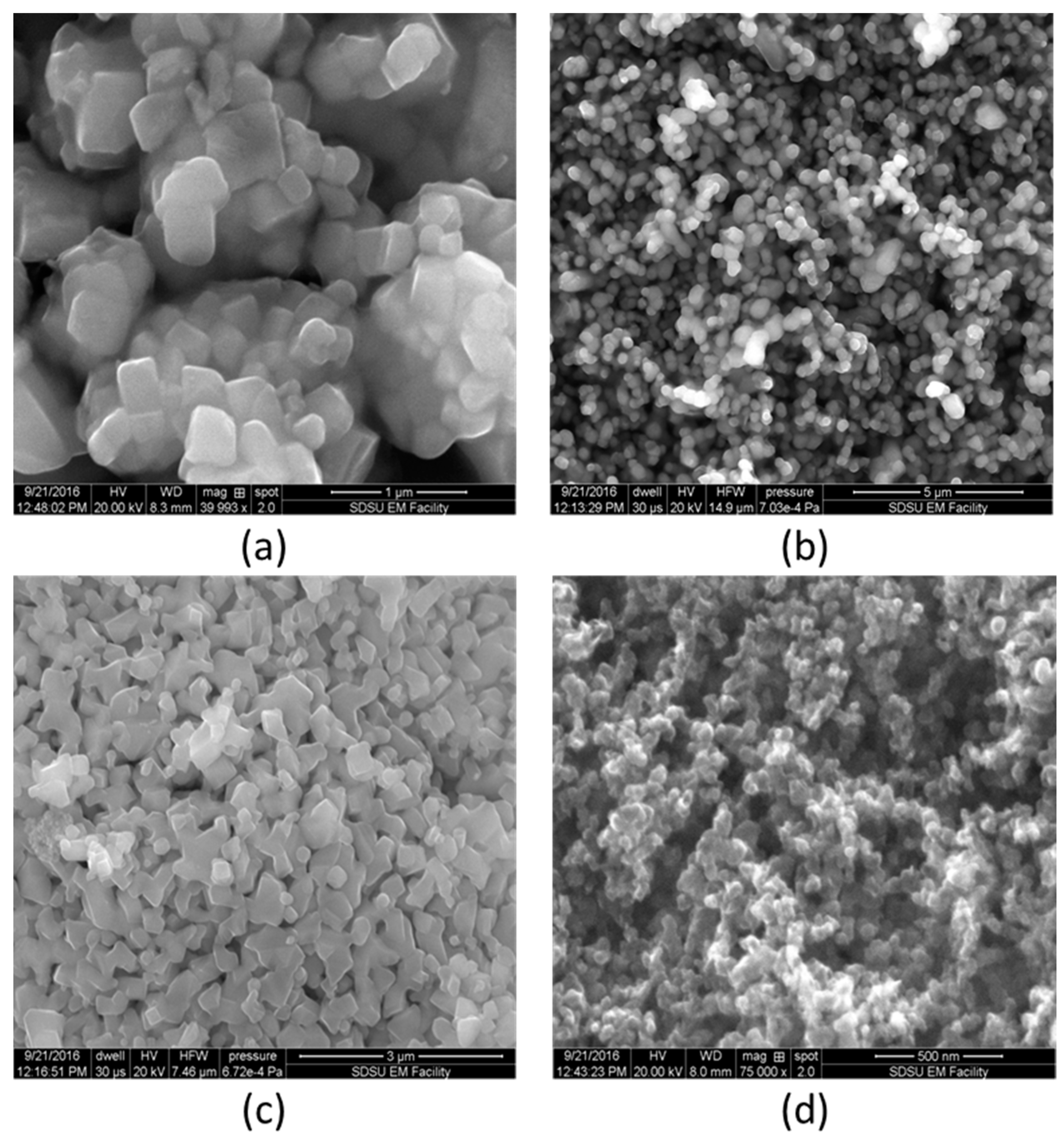
Figure 2.
Schematics of (a) regular three-layer and (b) functionally graded five-layer batteries.
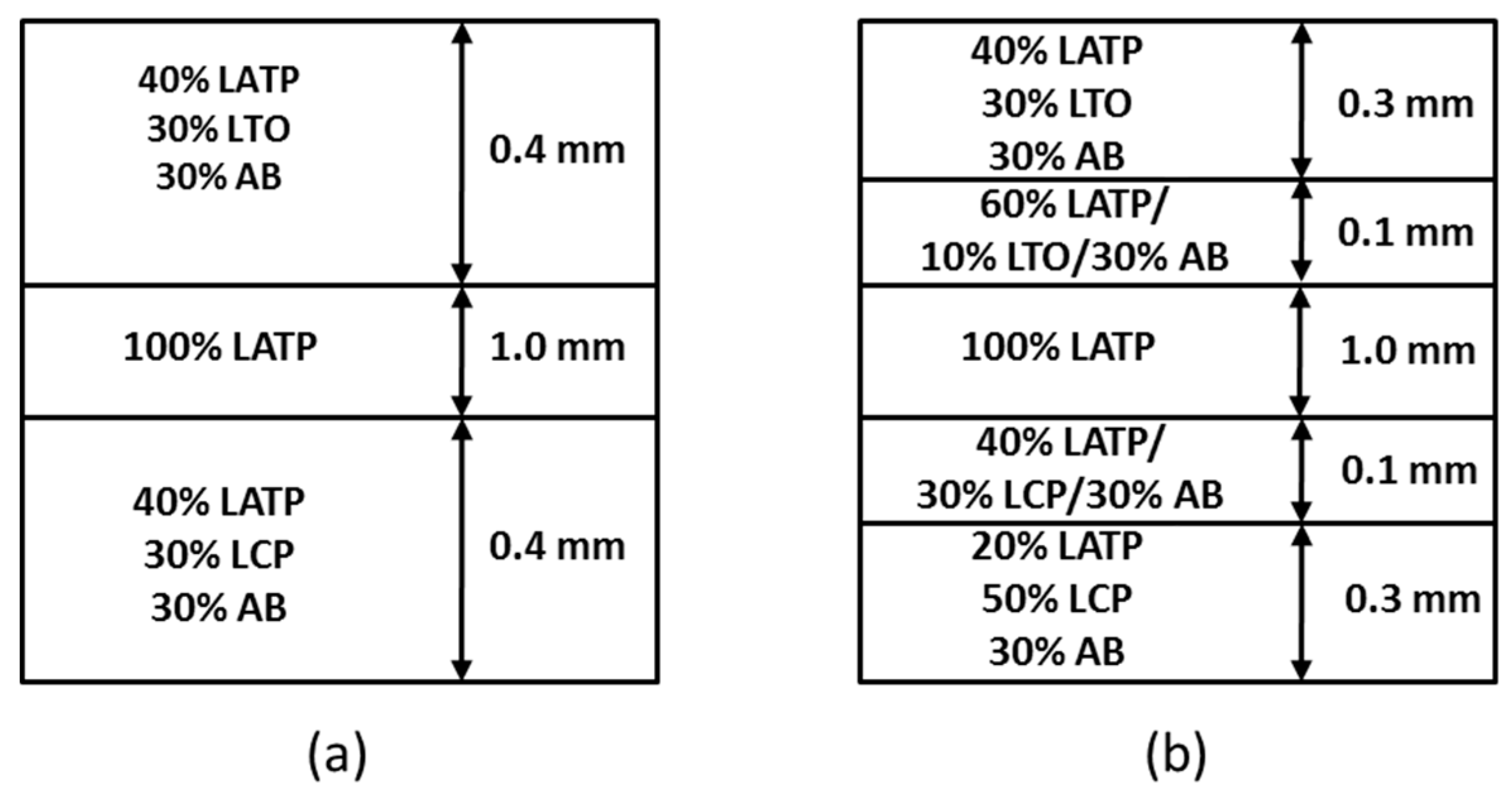
Figure 3.
Galvanostatic test results: (a) charge curves; (b) discharge curves.

Figure 4.
SEM images of the interfaces in the three-layer battery: (a) electrolyte–cathode; (b) anode–electrolyte; (c) anode–electrolyte at higher magnification.
Figure 4.
SEM images of the interfaces in the three-layer battery: (a) electrolyte–cathode; (b) anode–electrolyte; (c) anode–electrolyte at higher magnification.
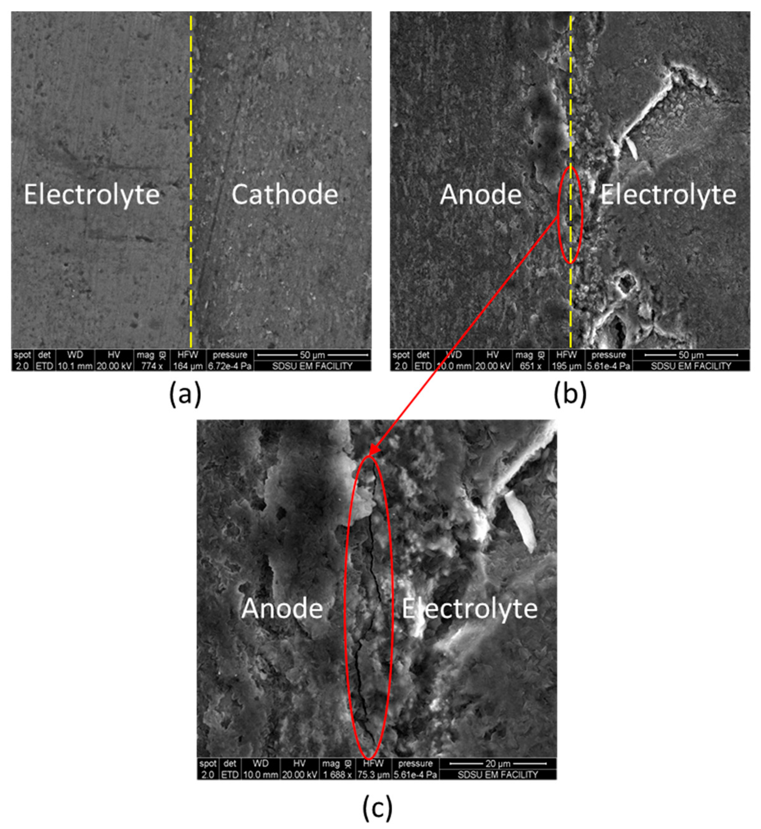
Figure 5.
SEM images of the interfaces in the five-layer battery: (a) cathode–intermediate cathode; (b) intermediate cathode–electrolyte; (c) electrolyte–intermediate anode; (d) electrolyte–intermediate anode at higher magnification; (e) intermediate anode–anode.
Figure 5.
SEM images of the interfaces in the five-layer battery: (a) cathode–intermediate cathode; (b) intermediate cathode–electrolyte; (c) electrolyte–intermediate anode; (d) electrolyte–intermediate anode at higher magnification; (e) intermediate anode–anode.


Table 1.
Completeness of batteries’ consolidation under different spark plasma sintering (SPS) conditions.
Table 1.
Completeness of batteries’ consolidation under different spark plasma sintering (SPS) conditions.
| No. | Temperature | Pressure | Holding | Anode | Cathod | Electrolyte | Joined |
|---|---|---|---|---|---|---|---|
| 1 | 650 °C | 45 MPa | 5 min | powder form | powder form | consolidated | No |
| 2 | 800 °C | 60 MPa | 10 min | partially consolidated | consolidated | consolidated | No |
| 3 | 825 °C | 80 MPa | 30 min | consolidated | consolidated | consolidated | Yes |
| 4 | 850 °C | 60 MPa | 10 min 1 | Melting occured at 850 °C | N/A | ||
1 Experiment stopped when melting occurred at the beginning of holding time.
Table 2.
Resistivity and conductivities of batteries, conductivities of the constituent materials that make up the battery.
© 2017 by the authors. Licensee MDPI, Basel, Switzerland. This article is an open access article distributed under the terms and conditions of the Creative Commons Attribution (CC BY) license (http://creativecommons.org/licenses/by/4.0/).
Share and Cite
MDPI and ACS Style
Wei, X.; Rechtin, J.; Olevsky, E.A. The Fabrication of All-Solid-State Lithium-Ion Batteries via Spark Plasma Sintering. Metals 2017, 7, 372. https://doi.org/10.3390/met7090372
AMA Style
Wei X, Rechtin J, Olevsky EA. The Fabrication of All-Solid-State Lithium-Ion Batteries via Spark Plasma Sintering. Metals. 2017; 7(9):372. https://doi.org/10.3390/met7090372
Chicago/Turabian StyleWei, Xialu, Jack Rechtin, and Eugene A. Olevsky. 2017. "The Fabrication of All-Solid-State Lithium-Ion Batteries via Spark Plasma Sintering" Metals 7, no. 9: 372. https://doi.org/10.3390/met7090372
Note that from the first issue of 2016, this journal uses article numbers instead of page numbers. See further details here.