Article

Effect of Post Weld Heat Treatment on the Microstructure and Mechanical Properties of a Submerged-Arc-Welded 304 Stainless Steel

1
Functional components and Materials R&D Group, Korea Institute of Industrial Technology, Yangsan 50635, Korea
2
School of Materials Science and Engineering, Pusan National University, Busan 46241, Korea
3
School of Materials Science and Engineering, University of Ulsan, Ulsan 44610, Korea
4
School of Materials Science and Engineering, Yeungnam University, Gyeongsan 38541, Korea
*
Authors to whom correspondence should be addressed.
Metals 2018, 8(1), 26; https://doi.org/10.3390/met8010026
Submission received: 8 November 2017 / Revised: 15 December 2017 / Accepted: 22 December 2017 / Published: 2 January 2018

Abstract

:
The present study is to investigate the effect of post heat treatment on the microstructures and mechanical properties of a submerged-arc-welded 304 stainless steel. The base material consisted of austenite and long strips of delta-ferrite surrounded by Cr-carbide, and the welds consisted of delta ferrite and austenite matrix. For the heat treatment at 850 °C or lower, Cr-carbides were precipitated in the weld metal resulting in the reduction of elongation. The strength, however, was slightly reduced despite the presence of Cr-carbides and this could possibly be explained by the relaxation of internal stress and the weakening of particle hardening. In the heat treatment at 1050 °C, the dissolution of Cr-carbide and disappearance of delta ferrite resulted in the lower yield strength and higher elongation partially assisted from deformation-induced martensitic transformation. Consequently, superior property in terms of fracture toughness was achieved by the heat treatment at 1050 °C, suggesting that the mechanical properties of the as-weld metal can be enhanced by controlling the post weld heat treatment.

1. Introduction

Austenitic stainless steels are widely used in important parts of chemical plants such as pressure vessels, chemical machineries, and pipes because they have excellent corrosion resistance, acid resistance, formability, and weldability. They are also extensively applied in gas turbines, jet propellants, and nuclear power plants because of their excellent toughness in high-temperature and high-pressure environments [1,2,3,4].
Submerged Arc Welding (SAW) is widely used for joining ship structures and piping thick-wall stainless steels [5,6]. In SAW, a solid filler wire is automatically inserted to pre-dispersed granular flux and an arc generates between the base metal and the filler wire while being covered with flux. The flux in contact with the arc melts and then the molten slag covers and protects the molten metal. Generally high-efficiency welding is achieved by flowing a large current through a large-diameter wire. It has the advantage of improving welding productivity through high speed solidification during welding and improving weld quality through welding heat control [7].
Due to the heat input from the SAW welding process, there is a degradation problem of microstructural and mechanical properties such as inhomogeneity of the microstructure, concentration of residual stress, brittleness, and deterioration of toughness in the welded material [8]. Post-weld heat treatment (PWHT) is usually introduced to solve such degradation. However, if the delta ferrite in austenitic stainless steel is excessively present in the weld metal during SAW welding, embrittlement of the welded part may occur due to transformation into another brittle phase such as a sigma phase during post heat treatment. In order to solve these problems, it is important to investigate post-heat treatment process to control the content of delta ferrite and the harmful carbides [9]. Proper post-heat treatment can improve the mechanical properties by homogenizing the microstructure of the welded material and controlling the formation of beneficial and harmful phases [10,11,12,13].
Although extensive researches have conducted on the effect of PWHT on the welded austenitic stainless steels, industrial field still requires the comprehensive research on the resultant effect of PWHT, especially for the practical and the cost effective process condition of PWHT. The present study thus investigated the effect of PWHT on the change of microstructural and mechanical properties of the welded part of AISI STS 304 steel produced by SAW. The microstructural changes during the heat treatment were analyzed and the resultant effect on mechanical properties were discussed.

2. Materials and Methods

In this study, submerged-arc welding was performed in austenitic stainless steel STS304 using STS308L as a welding electrode. The chemical compositions of the materials used are shown in Table 1. A plate with the width of 100 mm, the length of 1000 mm and the thickness of 25 mm was fabricated by the SAW. In order to evaluate the microstructure and mechanical properties, PWHT was performed from 650–1050 °C with an interval of 200 °C as shown in Figure 1a. After maintaining at these temperatures for 0.5–4 h, the specimens were then quenched in water.
In order to observe the microstructure, the test pieces were grinded using sandpapers and then were micro-polished using a diamond suspension with a 1 μm diameter. According to ASTM E-340, the polished surface was etched using a mixed solution of distilled water, hydrochloric acid and nitric acid with a ratio of 4:3:3. Through the optical microscopy, the microstructures of the base metal, the weld part and the heat affected zone (HAZ) were analyzed. According to ASTM E-8, subsized plate-type tensile specimens were taken from the middle of the welded plate with perpendicular to the welding direction as shown in Figure 1b.
The tensile tests were conducted to measure yield strength, tensile strength and elongation with the strain rate of 10−3/s according to ASTM A370 using universal tensile machine (MTS, Eden Praire, MN, USA). The yield strength was determined by the 0.2% offset method and the elongation was measured by the travel distance of crosshead. Vickers hardness test was conducted with the load of 2.94 N for 15 s dwell time and the hardness values were measured 10 times in total, and the average value was calculated by excluding the maximum and the minimum value. To measure the content of delta ferrite in the weld metal, the mean value was measured 10 times per specimen using FERITSCOPE-FMP30 (Fischer, Windsor, CT, USA). Electron backscattered diffraction (EBSD) and Electron Probe Microanalysis (EPMA) was performed to observe the phase change after post heat treatment using JEOL FE-SEM 7200F (JEOL, Tokyo, Japan). For thermodynamic calculations to predict the volume fraction of equilibrium phase at given temperatures, ThermoCalc software (Thermo-Calc Software, 2017b, Solna, Sweden) package was adopted with the latest steel database (TCFE9).

3. Results and Discussion

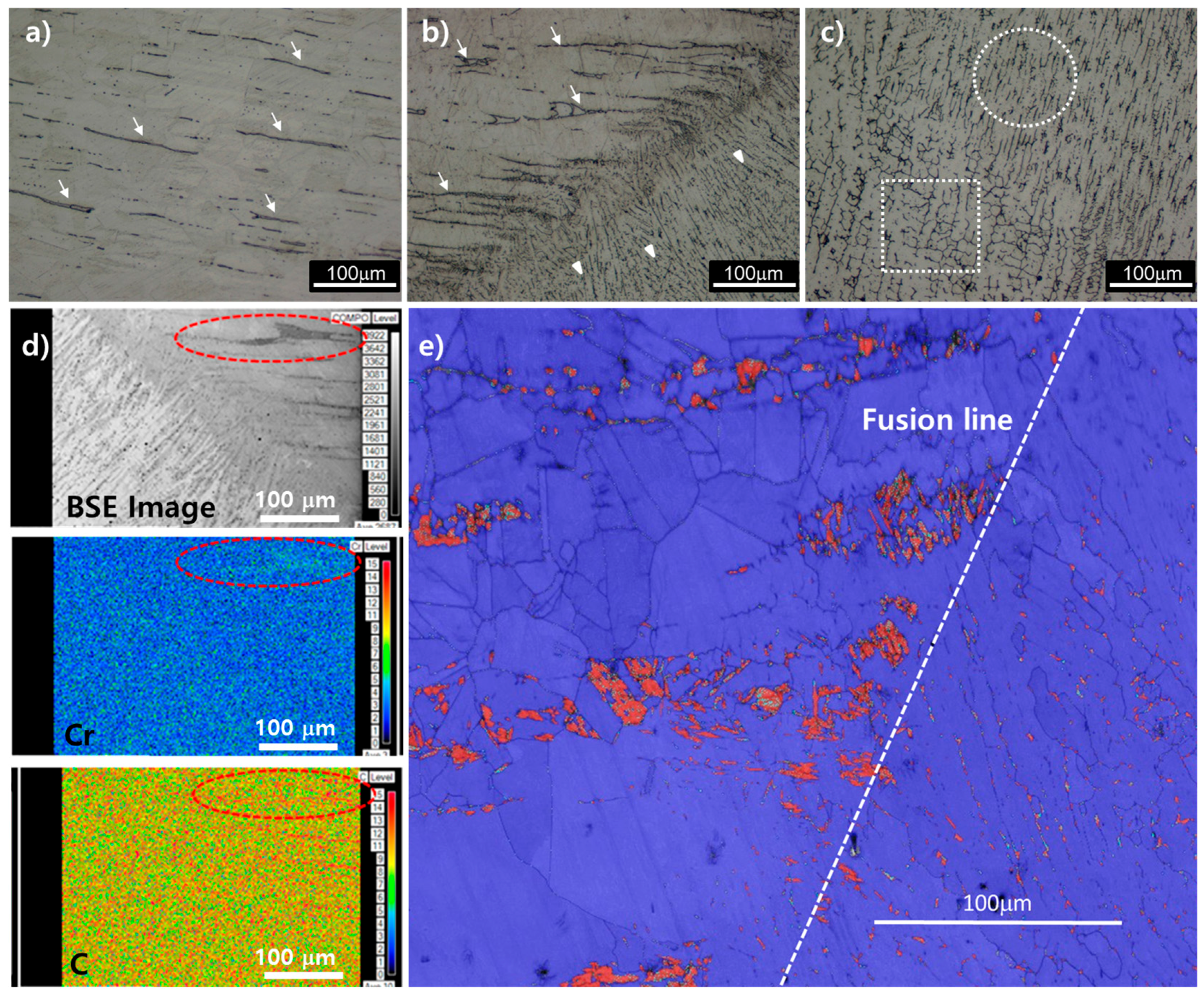
Figure 2 shows the microstructure of weld metal, heat-affected zone (HAZ) and base metal after sub-merged arc welding (SAW). The base metal consisted of austenite single phase and hot-rolling strips. These rolling strips correspond to delta ferrite surrounded by Cr-based carbides precipitated during hot rolling (Figure 2d–f). The weld metal was composed of austenite (white) and delta ferrite (black). The delta ferrite is classified into lathy and vermicular type by shape (white circle and rectangle in Figure 2c, respectively), and this shape difference is considered to be caused by welding heat input. In the sequential order of multi-pass SAW, the welded structure initially appeared in a lathy shape, and then the lathy shape was transformed into a twisty vermicular shape induced by the next welding pass. From the results of the Energy Dispersive Spectroscopy (EDS) analysis, it was confirmed that the formation of the primary Cr-carbide did not occur in the weld metal. Scanning electron microscope (SEM) analysis revealed that pores and cracks possibly formed during solidification were hardly found in the weld metal. Therefore, it was confirmed that the welding conditions such as welding power and electrodes were correctly selected.
The heat affected zone of the austenitic stainless steel is generally prone to be Cr-deficient due to the precipitation of Cr-Fe rich carbides at phase boundaries or grain boundaries causing brittleness and welding decay [14]. From the EPMA analysis in Figure 2d, there was no remarkable increase of Cr-carbide in HAZ, compared to the base metal where Cr-carbides initially present around long-elongated delta ferrite. Also the shape of Cr-carbides near HAZ still remained in a long elongated shape, which means that those carbides were likely to be formed during hot-rolling process. It is thus considered that the formation of Cr-carbide by welding heat effect hardly occurred in the present specimen. 
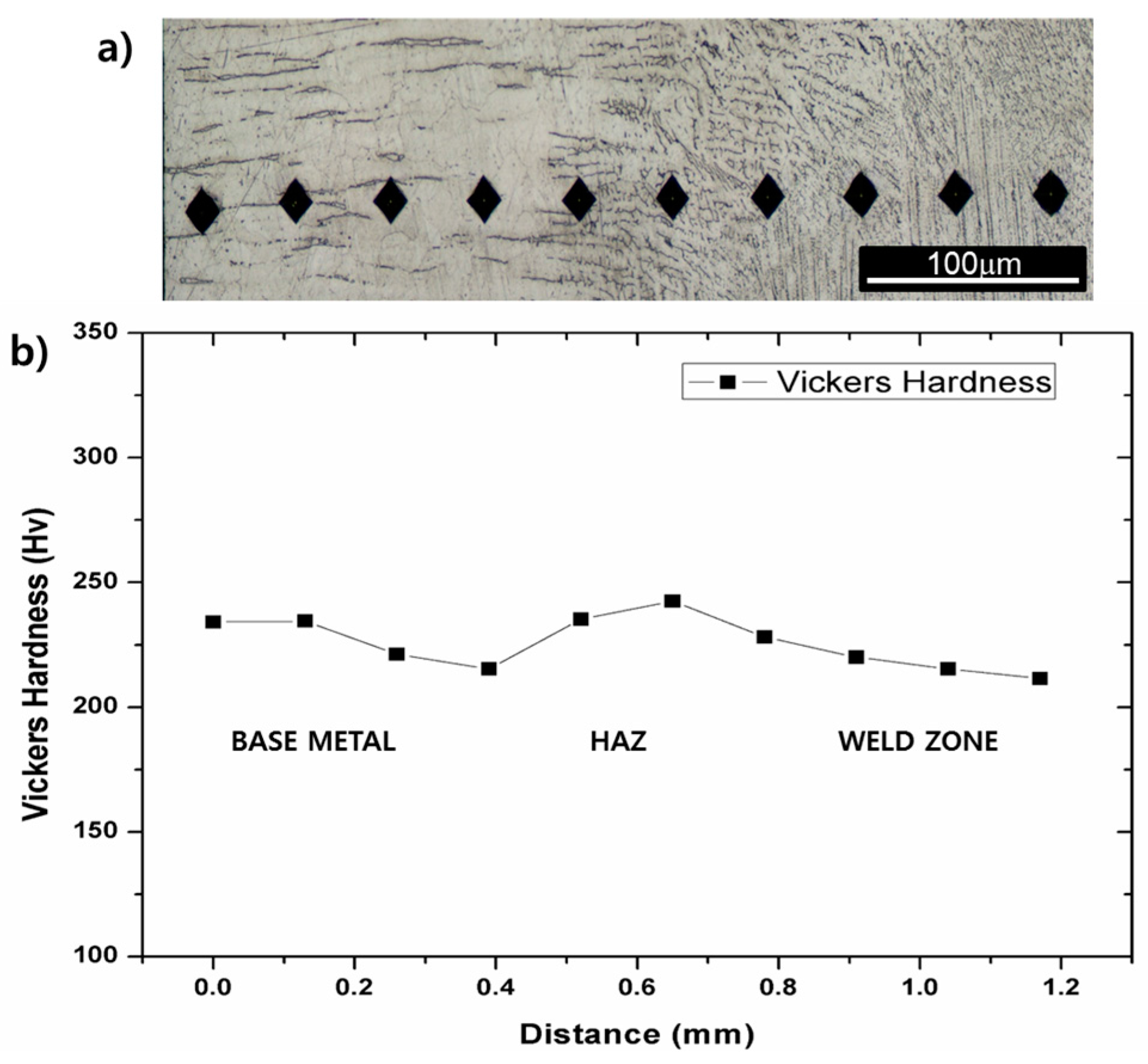
Figure 3a,b show Vickers hardness measured over base metal, HAZ and welding metal. The hardness value is considered not to vary significantly over those regions despite that the hardness increased at the regions where austenite and carbides existing together. The hardness of the base material and the HAZ were similar with each other and the hardness of the weld metal was slightly lower than those of the base metal and the HAZ. The hardness results provide that microstructural changes such as grain coarsening/refining or Cr-carbides precipitation barely occurs in the HAZ. The as-welded specimens were always fractured in the middle of the weld metal, not in the HAZ during tensile tests. This also indicates that there is almost no formation of brittle phases in the HAZ. Therefore, the analysis of microstructural changes and mechanical properties during post weld heat treatment is focused on the weld metal, not on the HAZ.
Figure 4 shows the microstructure of the base material and the HAZ after heat-treated at 650–850 °C for 0.5–4 h. The size of the austenite grain boundaries of the base material and the HAZ is 40–60 μm on average, which is not significantly changed, compared to the as-weld specimen. The strips already existing in the base material still remained, without noticeable changes in the shape and the volume fraction even after the heat treatment at 650 °C. In the 850 °C heat treatment, however, the volume of the strips decreased and their shapes were blurred as compared with the as-weld and the heat-treated specimens at 650 °C. It can be inferred that the Cr-based carbide was decomposed into an austenite phase at 850 °C.
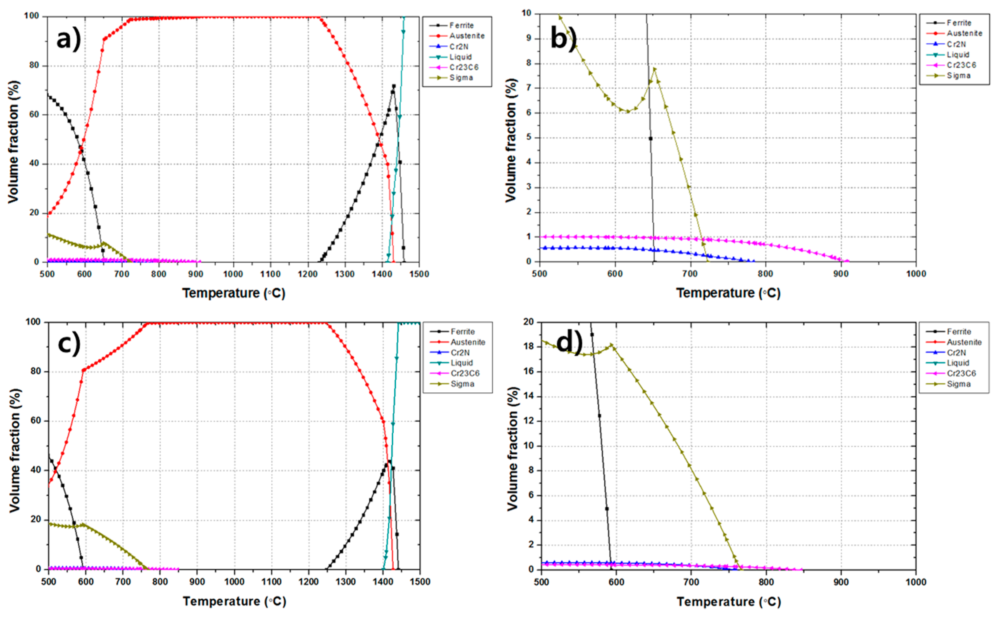
It has been reported that Cr-based carbide is precipitated and a delta phase is transformed into a sigma phase in the temperature range of 600–850 °C in 300-series austenitic stainless steels [11,15]. The results of the thermodynamic calculations in Figure 5 show that at 650 °C, about 1% of the Cr23C6 and 8% of the sigma phase can be precipitated in equilibrium from the base metal composition. This Cr23C6 is known to be precipitated in the austenite grain boundaries where segregated chromium atoms tend to be bound with carbon atoms. Therefore, the formation of Cr23C6 makes chromium concentration in the grain boundaries lowered, i.e., chromium depletion, which results in the less formation of the Cr-based oxides and thus provides harmful effect on corrosion properties and toughness of grain boundaries. On the other hand, sigma phase of a tetragonal structure composed of Fe-Cr-Ni-Mo is generally reported to be precipitated in ferrite/austenite phase boundaries and to be grown into ferrite phase [16,17]. In the present thermodynamic calculations, the sigma phase was expected to have a high fraction of 8%, which could be regarded as the much higher value than the actual experimental value. The reason for this overestimation is that the thermodynamic calculation does not consider kinetics of phase transformation; alpha ferrite was calculated to exist in 650 °C from the present thermodynamic calculation but was not actually present in the base metal where the single austenite phase only existed. In the base metal, the preferred nucleation site of the sigma phase, i.e., ferrite, is hardly existing, and thus the actual volume of the sigma phase could be much lower than the calculated predictions. On the other hand, in the case of the heat treatment at 850 °C, it was predicted that 0.4% of Cr23C6 phase would be precipitated and the sigma phase could not be precipitated. The volume fraction of Cr23C6 decreased with increasing temperature up to 900 °C above which the Cr-carbide would not be precipitated.
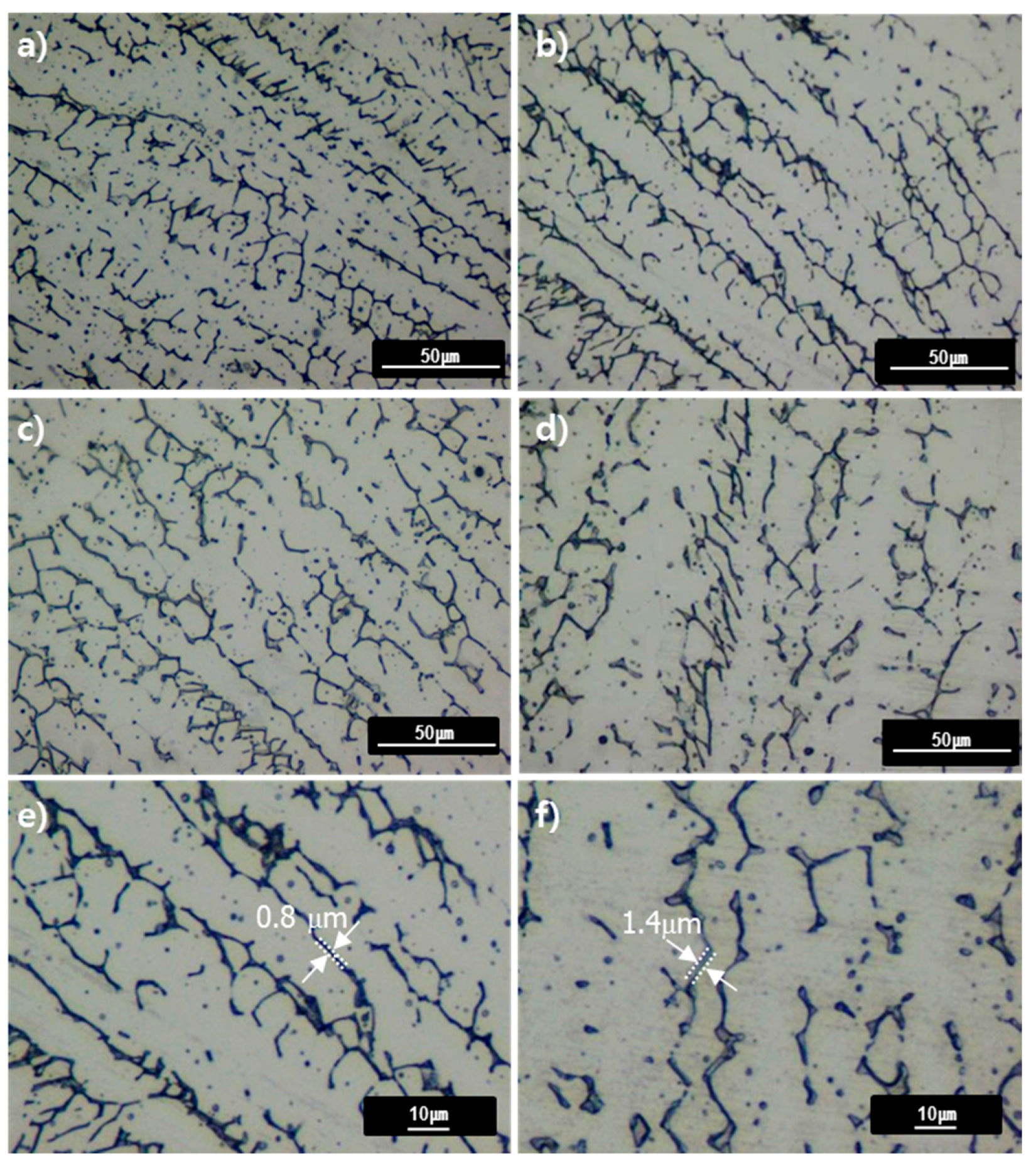
Figure 6 shows the microstructure of the weld metal heat-treated at 650–850 °C for 0.5 and 4 h. Similar to the as-weld microstructure, the austenite matrix contained delta ferrite dendrites. After heat treatment at 650–850 °C, the lathy type delta ferrite changed to vermicular type due to the heat treatment and the size of the individual dendrite of delta ferrite increased at 850 °C in comparison with 650 °C. The phase boundary between austenite and delta ferrite is considered to migrate in favor of reducing the interfacial energy. The initially thin dendrites of delta ferrite could thus be thicker during heat treatment without losing their total volume fraction as confirmed in Figure 6e,f. The fraction of delta ferrite was measured to be slightly decreased during heat treatment at 650–850 °C. 
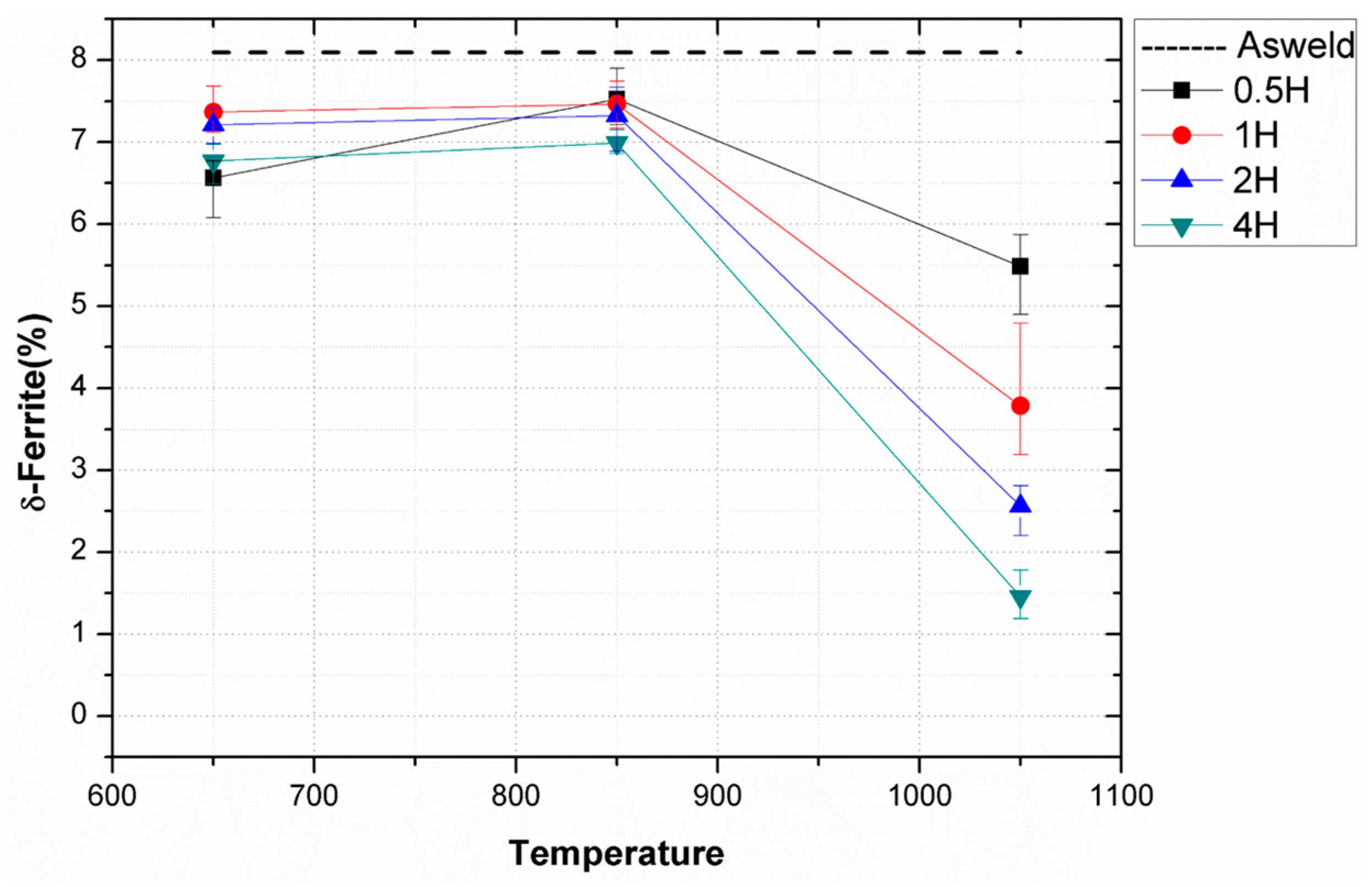
Figure 7 shows the volume fractional change of delta ferrite with temperature and time obtained from the magnetic induction method. Because possible phases such as austenite, Cr-carbide, and sigma phase are all paramagnetic, only ferromagnetic ferrite reacts to the magnetic induction, so that the surface volume fraction of ferrite can be precisely measured [18]. At 650–850 °C, the ferrite fraction of the weld metal was reduced by 1% compared to the as-weld specimen. From the thermodynamic calculation results shown in Figure 5c, a small amount of ferrite has been transformed into austenite because the Ae3 temperature is less than 650 °C. However, as observed from optical photographs in Figure 6, the volume fraction variation of delta ferrite seems to be insignificant but rather the size of individual delta ferrite is likely to become larger as temperature increases from 650 to 850 °C.
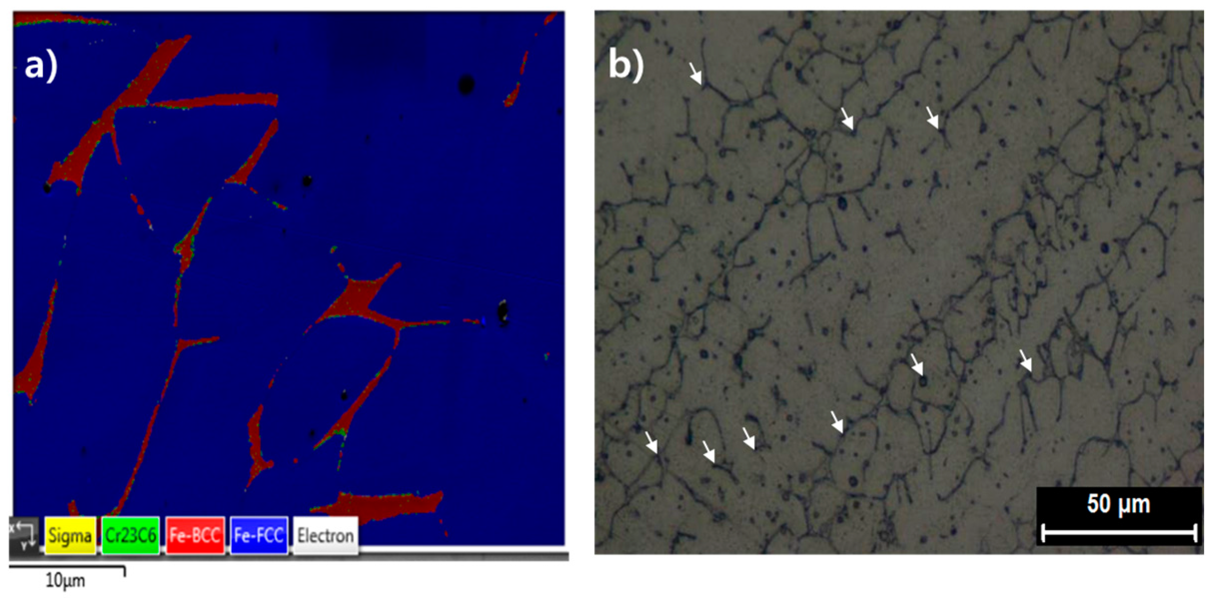
Figure 8 is the EBSD phase map that shows the presence of Cr23C6 in the weld after annealing at 650 °C for 4 h. The Cr23C6, which did not exist in the as-weld specimen, was found to precipitate finely in the austenite/delta-ferrite interface after 4 h of heat treatment at 650 °C. Cr23C6 carbide is reported to precipitate from austenite/ferrite phase boundary or austenite grain boundary in 300-series austenitic stainless steels [11,15,16]. After precipitation, it grows into austenite matrix rather than ferrite matrix. It is known that the precipitates are finely located in the boundaries with the size distribution from several hundred nm to few μm, depending on the composition and the formation temperature [15]. As can be seen from the thermodynamic calculations shown in Figure 5, the temperature range near 650 °C could have 0.5% volume fraction of Cr23C6, which is the maximum value in whole temperature range. Although it is a small volume fraction, it is presumed that if the precipitates are finely distributed along the phase boundaries, it could deteriorate the ductility and toughness of the material. In the thermodynamic calculation, it was predicted that about 12% of the sigma phase would be precipitated in the weld metal at 650 °C. However, the EBSD results hardly showed the presence of sigma phase. It is believed that the transformation kinetics of sigma phase is relatively slow, so that sigma phase could not be transformed from ferrite with the given temperature and time. Even if sufficient time is provided, it is expected that the sigma phase would not be present as much as the predicted value since the volume fraction of ferrite, which is the preferred nucleation site of the sigma phase, is relatively small in the actual weld metal.
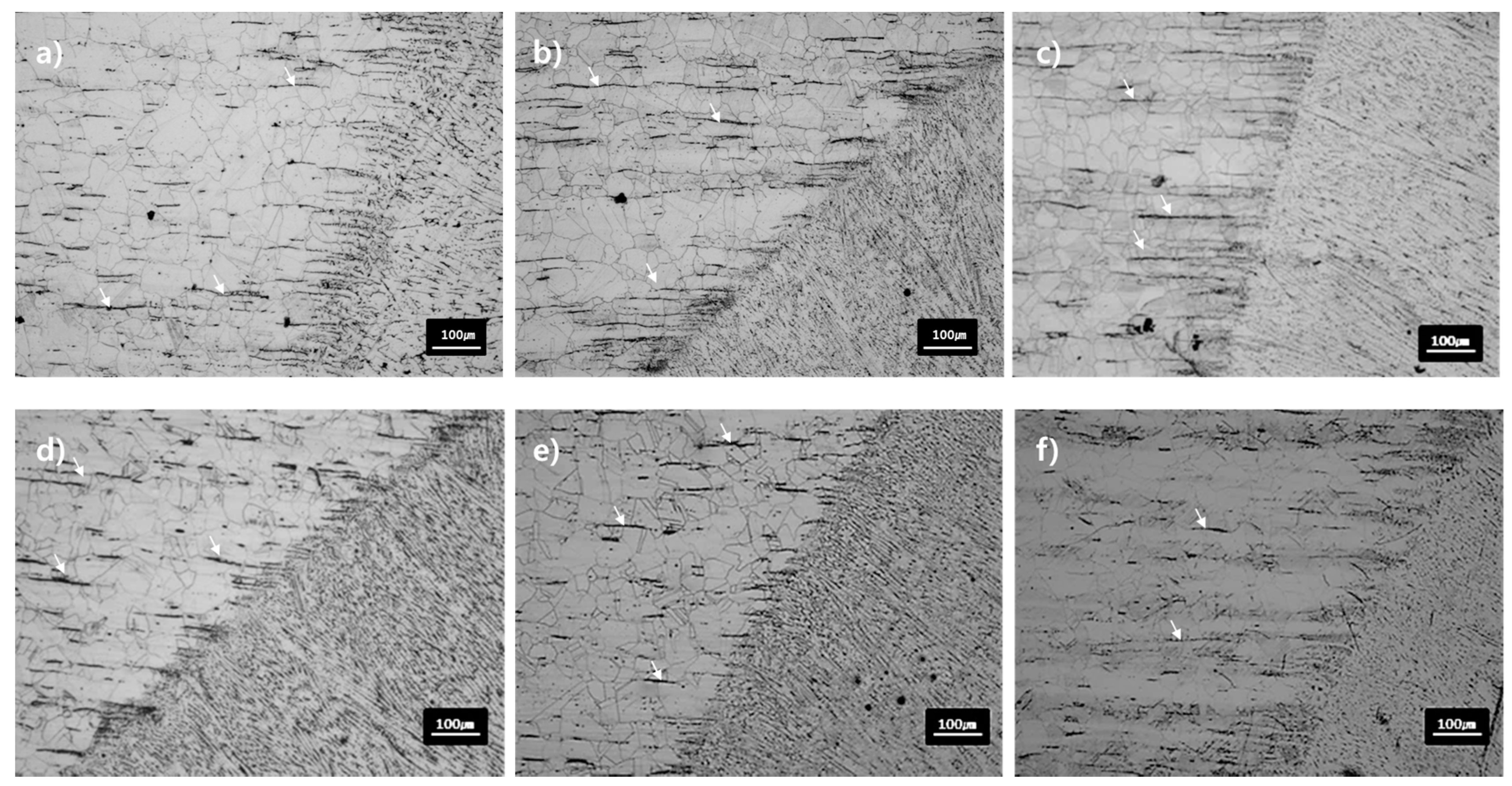
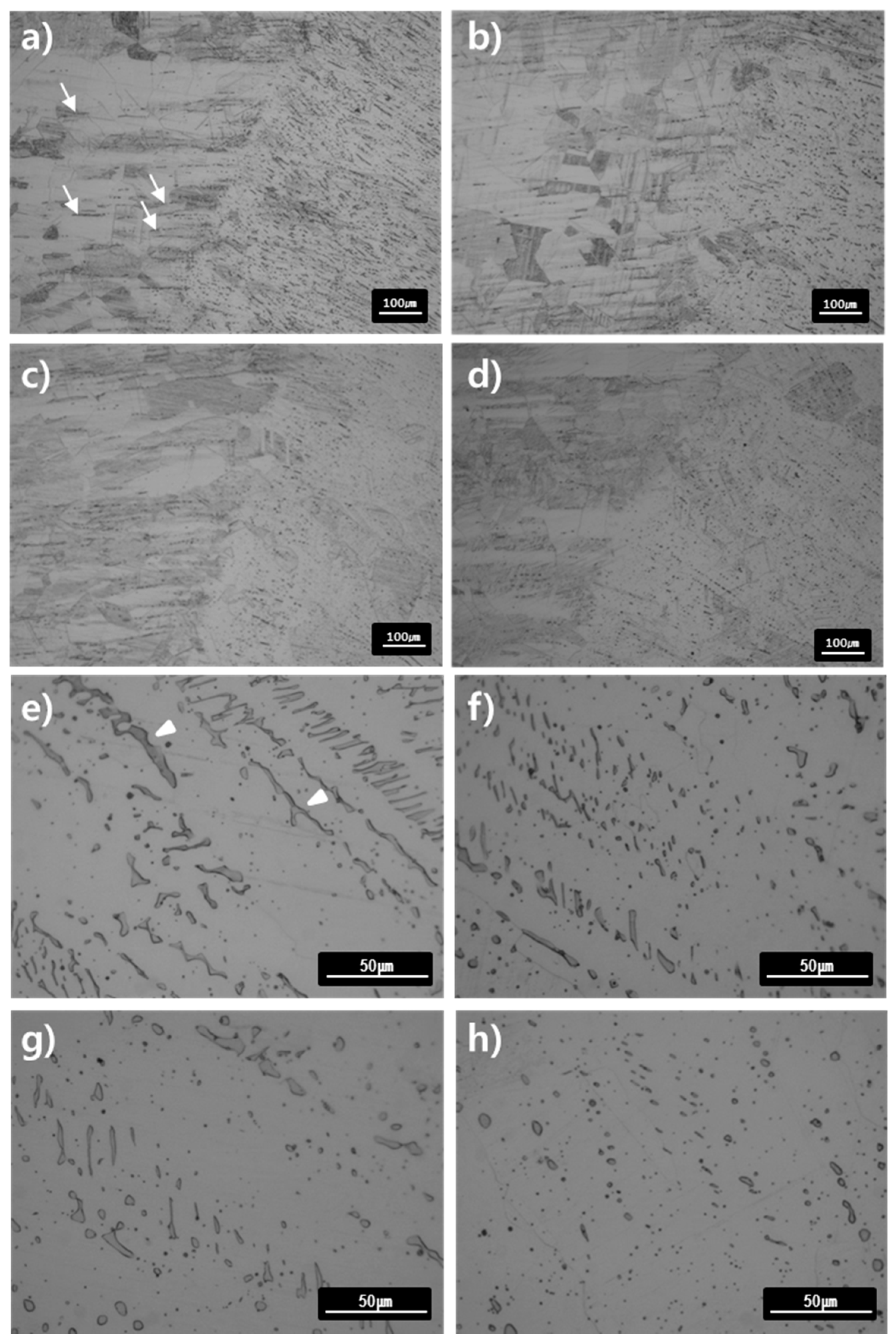
Figure 9a–d show the microstructures of the base material and HAZ of the specimens annealed at 1050 °C for 0.5–4 h. The grain size of the base metal after PWHT in 1050 °C for 4 h became larger (72 μm) than the as-weld specimen (52 μm), which shows the grain growth of austenite with increasing time and temperature. This grain growth is believed to occur because of the acceleration of thermally-assisted migration of the austenite grain boundary. The strip already existing in the base metal was observed to disappear as the heat treatment time became longer. As can be seen from the thermodynamic calculation in Figure 5, the Cr-based carbide was considered to transform into the austenite phase at 1050 °C since the dissolution temperature of the Cr-based carbide is about 900 °C.
Figure 9e–h shows the microstructure of welded specimens after heat treatment at 1050 °C for 0.5–4 h. The delta ferrite, which existed as lathy or vermicular shape in the as-weld specimen, lost its shape into the elliptical or the spheroidized after the heat treatment of 1050 °C. This is due to the migration of austenite/delta-ferrite interface for decreasing the interfacial energy, similar to the mechanism of the shape change from the lathy to the vermicular type observed in the heat treatment at 650–850 °C. The volume fraction of delta ferrite at 1050 °C decreased by heat treatment time as confirmed in Figure 7 where delta-ferrite, which was 8% of volume fraction in the as-weld specimen decreased down to 1.2% after heat treatment at 1050 °C for 4h. From the thermodynamic point of view, the transformation of delta ferrite to austenite was believed to be promoted at 1050 °C, well above the Ae3 temperature. From the thermodynamic calculations, austenite single phase exists at 1050 °C, without Cr-carbide or delta-ferrite phase, and well agree with the experimental observations. The residual delta-ferrite, which was not transformed into austenite by the rapid cooling after the welding, was gradually austenized by heat treatment at 1050 °C. In addition, at that temperature, residual stress due to welding could be released and carbides could dissolve sufficiently, which could possibly lead to noticeable changes in the mechanical properties.
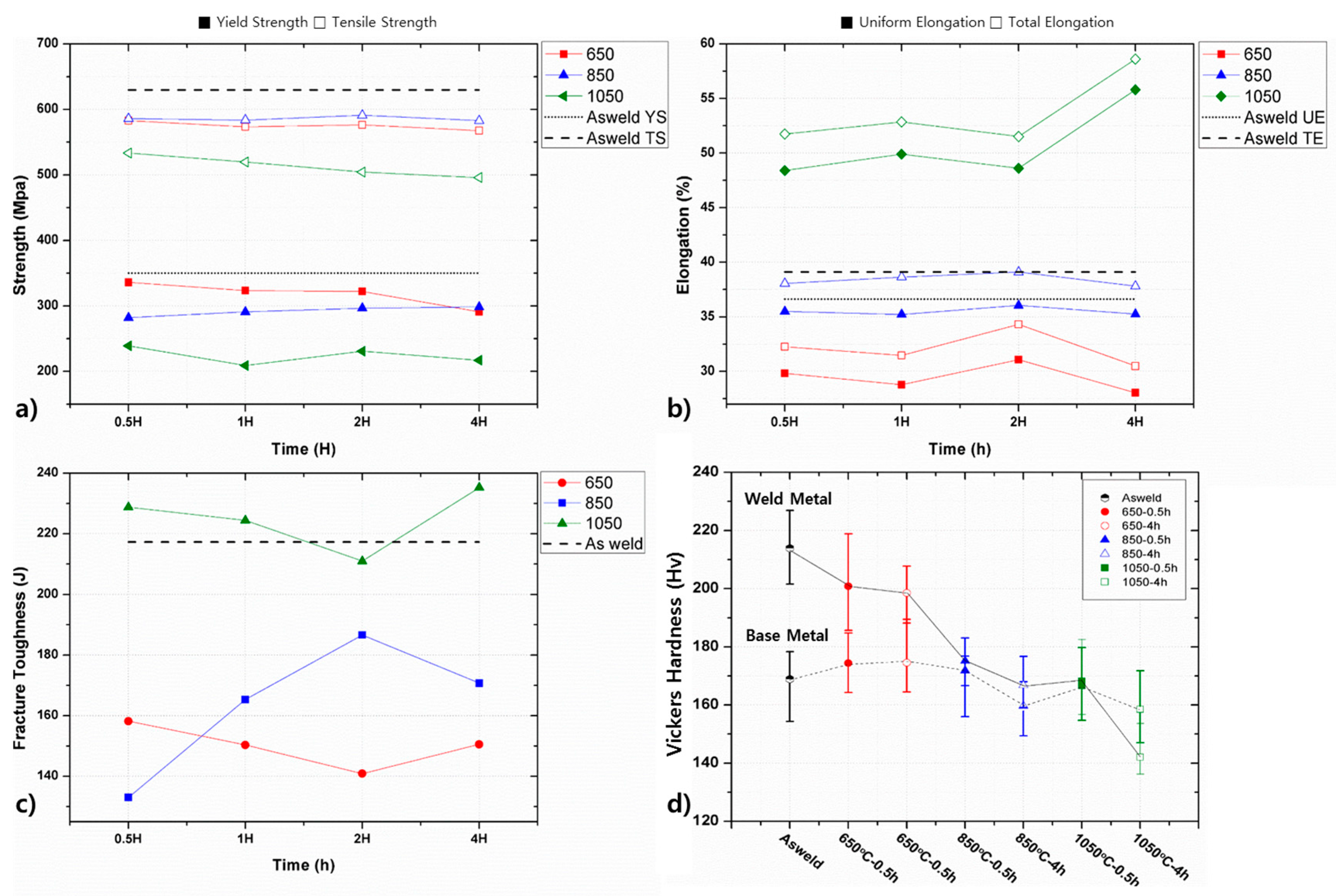
Figure 10 summarized the yield and tensile strength, uniform and total elongation, and fracture toughness of specimens after PWHT. The yield and tensile strengths in all range of heat treatment temperatures and times were lower than those of the as-weld specimen. The yield strength gradually decreased as the temperature increased while there was no significant change depending on the time. The tensile strength of the specimens heat-treated at 650–850 °C was 570–580 MPa and a noticeable difference was hardly found depending on the heat treatment time. In the case of the heat treated specimen at 1050 °C, the tensile strength was markedly lower and continuously decreasing with the time. As shown in Figure 10b, the uniform and total elongation decreased with increasing temperature up to 850 °C, compared with the as-weld specimen. On the other hand, the specimen at 1050 °C showed higher elongation than the as-weld specimen, and prolonged its elongation as the heat treatment time increased.
These changes of mechanical properties can be understood based on the microstructural evolution during heat treatment. In the case of reduction in strength and ductility shown at 650–850 °C, relaxation of internal stress, decreased volume fraction of delta ferrite and increased size of individual delta ferrite dendrite could be responsible for such degradation. As shown in Figure 8, the carbides were found to form in the austenite/ferrite phase boundaries. It is expected that material strength would increase by compromising ductility with the formation of Cr-carbide, but inversely the strength decreased at the corresponding temperature. This reduction in strength, first of all, could probably be explained by the stress relaxation due to the recovery of the hot-rolled microstructure in the base metal and by the relaxation of the internal stress in the base and the weld metal initially caused by the welding process [19]. Second, as shown in Figure 7, the slight decrease in volume fraction of the delta ferrite in the weld metal could possibly cause the strength reduction in terms of modulus hardening. Third, as can be seen in Figure 6, when the individual size of the delta ferrite increased without losing its volume fraction substantially, the strength can be reduced owing to the weakening of dispersion strengthening or precipitation strengthening [20]. Stochastically, the probability of the existence of dislocation sources is higher in the austenite matrix whose volume fraction and size is much higher than delta ferrite. Given that austenite has generally lower yield strength than ferrite, the operation of dislocation is likely to initiate in the austenite matrix. The dislocation movement in the austenite could then be impeded by stiff delta ferrite arrays and if the individual size of the delta ferrite increased, particle strengthening could be degraded.
On the other hand, in the case of heat treatment above 1050 °C, the yield and tensile strengths were lower but elongations were higher than the as-weld specimen. As shown in Figure 8, the decrease in the volume fraction of delta ferrite at 1050 °C is considered to be the cause of the strength reduction. Since the thickness of delta ferrite was small as about 1–2 μm, it is believed that the delta ferrite is strengthening the weld metal in terms of modulus hardening and particle hardening. Therefore, decreasing the fraction of delta ferrite may have affected the decrease of strength and increase of elongation inversely. In addition, as shown in Figure 9, the austenite grain size of the base and welds increased during the heat treatment at 1050 °C, and thus Hall-Petch effect due to the increase of grain size also has an effect on the reduction in yield and tensile strengths. Furthermore, the stress relaxation due to the heat treatment at 1050 °C could make the base and weld metal softer. Figure 10c shows the fracture toughness obtained by integrating stress-strain curves. When heat treatment temperature was in the range of 650–850 °C, the fracture toughness was lower than that of the as-weld specimen. When the heat treatment temperature was more than 1050 °C, the fracture toughness was in overall similar or higher than the as-weld specimen. In the temperature range studied in the present work, the strengths were reduced as compared with the as-weld specimen, but ductility significantly increased at 1050 °C. This ductility increase is reflected in the increase of the fracture toughness, and the PWHT at a temperature of 1050 °C was found to provide positive effect on improving the toughness of the as-weld material.
Figure 10d shows the hardness variation of the welds with the PWHT temperature and time. After 10 times of indentations, the values were averaged by excluding the maximum and the minimum. Hardness is determined by the magnitude of strengthening under compression, and thus it can be interpreted similarly to the strength. Vickers hardness showed a monotonic decrease with increasing the heat treatment temperature. The hardness change with the heat treatment time was negligible for 1 to 4 h, and temperature was more of an influential factor on the hardness. As described above, reduction of hardness with increasing temperature is also able to be explained by the relaxation of the residual stress, the decrease of delta-ferrite volume fraction and the increase of the individual delta ferrite thickness.
Figure 11 contained the true stress-strain curves together with work hardening rate for analyzing the difference in work hardening behaviors after PWHT. In the as-weld specimen, the work hardening rate decreased rapidly after passing yield point and maintained in the steady state. On the other hand, the work hardening rate of the specimen at 650 °C for 2 h was generally higher than that of the as-weld specimen, and decreased continuously with further straining after having a short steady-state flow regime. The work hardening rate of PWHT 850 °C increased continuously with deformation after reaching the steady state. This is presumably due to the deformation-induced martensitic transformation (DIMT) occurring in both of 304 base metal and 308 weld metal. When the DIMT occurs, the martensite phase is produced with the deformation, and the volume fraction of martensite increases steadily as the deformation continues, leading to the gradual increase of the work hardening rate [18]. The inflection shown in true stress-strain curve is related to the initiation of DIMT. A number of researches reported that the DIMT indeed occurs in 300-series austenitic stainless steels and results in the continuous increase of the work hardening rate during deformation [18,21,22]. At 1050 °C, the work hardening rate gradually increased and an inflection was observed in true stress-strain curve. In this temperature, the initially present Cr-carbide arrays would dissolve and thus make austenite matrix denser with carbon atoms. The austenite is thus more stabilized and the DIMT kinetics could be slower, leading to the increase of elongation. Since the delta ferrite already existing in the weld metal was mostly transformed into austenite and also the grain size of austenite increased at 1050 °C, the yield strength became lower than the as-weld specimen.

4. Conclusions

The effect of PWHT on the microstructure and mechanical properties of submerged-arc-welded 304 austenitic stainless steel was investigated. The results are summarized as follows:
(1)
The base metal initially had a microstructure consisting of austenite matrix and strips of delta-ferrite surround by Cr23C6. The weld metal consisted of lathy and vermicular type of delta ferrite and austenite matrix. There was insignificant variation of microstructures and mechanical properties between HAZ and the base metal, implying that heat affection by welding was negligible.
(2)
Cr-carbides were precipitated at the delta-ferrite/austenite interface in the weld metal after the heat treatment at 650–850 °C. Despite of the presence of Cr-carbide, the yield strength was lower than the as-weld specimen, which could be possibly explained by the relaxation of internal stress accumulated during the hot-rolling and the welding.
(3)
After heat-treatment at 1050 °C, the pre-existing strips in the base metal was dissolved into austenite and the delta-ferrite of the weld metal was transformed into austenite, leading to the microstructure close to the austenite single phase. Although the yield strength was lower than that of the as-weld specimen due to the disappearance of hard phases and the relaxation of residual stress, the elongation became higher than that of the as-weld metal due to the compromising effect of strength and partially to the DIMT occurring during deformation. In terms of fracture toughness, the heat treatment at 1050 °C were suggested to provide superior property than as-weld material due to the trade-off between strength and ductility.

Acknowledgments

This study has been conducted with the support of the Korea Institute of Industrial Technology as “Development of metal powder large-area DED process including pre- and post- processes based on simulations (KITECH EO-17-0041)” and “Development of Manufacturing Technology of Cryogenic Stainless Steel Welded Steel Pipe (KITECH JG-17-0006)”.

Author Contributions

Tae-Hoon Nam and Jong Bae Jeon conceived and designed the experiments; Tae-Hoon Nam and Eunsol An performed the experiments; Byung Jun Kim, Sunmi Shin, Nokeun Park, Won-Seok Ko, Namhyun Kang and Jong Bae Jeon analyzed and discussed the data; Tae-Hoon Nam and Jong Bae Jeon wrote the paper.

Conflicts of Interest

The authors declare no conflict of interest.

References

  1. Weiss, B.; Stickler, R. Phase instabilities during high temperature exposure of 316 austenitic stainless steel. Metall. Trans. 1972, 3, 851–866. [Google Scholar] [CrossRef]
  2. Chen, X.H.; Lu, J.; Lu, L.; Lu, K. Tensile properties of a nanocrystalline 316L austenitic stainless steel. Scr. Mater. 2005, 52, 1039–1044. [Google Scholar] [CrossRef]
  3. Menthe, E.; Rie, K.T. Further investigation of the structure and properties of austenitic stainless steel after plasma nitriding. Surf. Coat. Technol. 1999, 116–119, 199–204. [Google Scholar] [CrossRef]
  4. Altenberger, I.; Scholtes, B.; Martin, U.; Oettel, H. Cyclic deformation and near surface microstructures of shot peened or deep rolled austenitic stainless steel AISI 304. Mater. Sci. Eng. A 1999, 264, 1–16. [Google Scholar] [CrossRef]
  5. Tabatabaeipour, S.M.; Honarvar, F. A comparative evaluation of ultrasonic testing of AISI 316L welds made by shielded metal arc welding and gas tungsten arc welding processes. J. Mater. Process. Technol. 2010, 210, 1043–1050. [Google Scholar] [CrossRef]
  6. Li, X.R.; Zhang, Y.M.; Kvidahl, L. Penetration Depth Monitoring and Control in Submerged Arc Welding. Weld. J. 2013, 92, 48–56. [Google Scholar]
  7. Gunaraj, V.; Murugan, N. Application of response surface methodology for predicting weld bead quality in submerged arc welding of pipes. J. Mater. Process. Technol. 1999, 88, 266–275. [Google Scholar] [CrossRef]
  8. Gunaraj, V.; Murugan, N. Prediction and comparison of the area of the heat-affected zone for the bead-on-plate and bead-on-joint in submerged arc welding of pipes. J. Mater. Process. Technol. 1999, 95, 246–261. [Google Scholar] [CrossRef]
  9. Kumar, S.; Shahi, A.S. Effect of heat input on the microstructure and mechanical properties of gas tungsten arc welded AISI 304 stainless steel joints. Mater. Des. 2011, 32, 3617–3623. [Google Scholar] [CrossRef]
  10. Luo, J.; Dong, Y.; Li, L.; Wang, X. Microstructure of 2205 duplex stainless steel joint in submerged arc welding by post weld heat treatment. J. Manuf. Process. 2014, 16, 144–148. [Google Scholar] [CrossRef]
  11. Hamada, I.; Yamauchi, K. Sensitization behavior of type 308 stainless steel weld metals after postweld heat treatment and low-temperature aging and its relation to microstructure. Metall. Mater. Trans. A 2002, 33, 1743–1754. [Google Scholar] [CrossRef]
  12. Jang, D.; Kim, K.; Kim, H.C.; Jeon, J.B.; Nam, D.-G.; Sohn, K.Y.; Kim, B.J. Evaluation of Mechanical Property for Welded Austenitic Stainless Steel 304 by Following Post Weld Heat Treatment. Korean J. Met. Mater. 2017, 55, 664–670. [Google Scholar] [CrossRef]
  13. Kang, N.-H. Development of Alloy Design and Welding Technology for Austenitic Stainless Steel. J. KWJS 2010, 28, 10–14. [Google Scholar] [CrossRef]
  14. Barbosa Gonçalves, R.; Henrique Dias de Araújo, P.; José Villela Braga, F.; Augusto Hernandez Terrones, L.; Pinheiro da Rocha Paranhos, R. Effect of conventional and alternative solution and stabilizing heat treatment on the microstructure of a 347 stainless steel welded joint. Weld. Int. 2017, 31, 196–205. [Google Scholar] [CrossRef]
  15. Tseng, C.C.; Shen, Y.; Thompson, S.W.; Mataya, M.C.; Krauss, G. Fracture and the formation of sigma phase, M23C6, and austenite from delta-ferrite in an AlSl 304L stainless steel. Metall. Mater. Trans. A 1994, 25, 1147–1158. [Google Scholar] [CrossRef]
  16. Kington, A.V.; Noble, F.W. σ phase embrittlement of a type 310 stainless steel. Mater. Sci. Eng. A 1991, 138, 259–266. [Google Scholar] [CrossRef]
  17. Vitek, J.; David, S. The sigma phase transformation in austenitic stainless steels. Weld. J. 1986, 65, 106s–111s. [Google Scholar]
  18. Shin, H.C.; Ha, T.K.; Chang, Y.W. Kinetics of deformation induced martensitic transformation in a 304 stainless steel. Scr. Mater. 2001, 45, 823–829. [Google Scholar] [CrossRef]
  19. Mújica Roncery, L.; Weber, S.; Theisen, W. Welding of twinning-induced plasticity steels. Scr. Mater. 2012, 66, 997–1001. [Google Scholar] [CrossRef]
  20. Zhang, Z.; Chen, D.L. Consideration of Orowan strengthening effect in particulate-reinforced metal matrix nanocomposites: A model for predicting their yield strength. Scr. Mater. 2006, 54, 1321–1326. [Google Scholar] [CrossRef]
  21. Huang, C.X.; Yang, G.; Deng, B.; Wu, S.D.; Li, S.X.; Zhang, Z.F. Formation mechanism of nanostructures in austenitic stainless steel during equal channel angular pressing. Philos. Mag. 2007, 87, 4949–4971. [Google Scholar] [CrossRef]
  22. Lee, T.-H.; Oh, C.-S.; Kim, S.-J. Effects of nitrogen on deformation-induced martensitic transformation in metastable austenitic Fe–18Cr–10Mn–N steels. Scr. Mater. 2008, 58, 110–113. [Google Scholar] [CrossRef]
Figure 1. Schematic diagrams showing (a) post-weld heat treatment schedules and (b) ASTM-E8 subsized tensile specimen.
Metals 08 00026 g001
Figure 2. Optical micrographs of the as-weld specimen showing (a) the base metal, (b) the heat-affected zone, and (c) the weld metal (White arrows and triangles are indicating the pre-existing strips and delta ferrite, respectively.); (d) Electron Probe Microanalysis (EPMA) images showing the presence of Cr-carbides in the base metal; (e) Electron backscattered diffraction (EBSD) phase map on the fusion line including base metal (right) and heat affected zone (HAZ) (left). Red, blue, and cyan color indicate delta-ferrite, austenite, and Cr23C6, respectively.
Metals 08 00026 g002
Figure 3. (a) Optical micrographs indicating the indenting positions; (b) Vicker hardness measured through the base metal, the HAZ, and the weld metal.
Metals 08 00026 g003
Figure 4. Optical micrographs on the base metal and the HAZ of the heat-treated specimens at (a) 650 °C for 0.5 h, (b) 650 °C for 1 h, (c) 650 °C for 4 h, (d) 850 °C for 0.5 h, (e) 850 °C for 1 h, and (f) 850 °C for 4 h. Arrows indicating pre-existing strips of delta ferrite and Cr-carbide in the HAZ, respectively.
Metals 08 00026 g004
Figure 5. Predicted volume fraction of equilibrium phases at given temperatures in (a,b) the base metal (STS 304) and (c,d) the filler metal (STS 308L).
Metals 08 00026 g005
Figure 6. Optical micrographs (OM) on the weld metal of the heat-treated specimens for (a) 0.5 h at 650 °C, (b) 4 h at 650 °C, (c) 0.5 h at 850 °C, and (d) 4 h at 850 °C, respectively. To show the thickening of delta ferrite dendrite, markers indicate the thickness of delta ferrite dendrite for the heat-treated specimens for (e) 4 h at 650 °C and (f) 4 h at 850 °C.
Metals 08 00026 g006
Figure 7. Volume fraction of delta ferrite in the weld metal measured by magnetic induction method.
Metals 08 00026 g007
Figure 8. (a) EBSD map showing presence of Cr23C6 at phase boundary; (b) OM image after color-etching showing the presence of Cr23C6 (dark).
Metals 08 00026 g008
Figure 9. Optical micrographs on the base metal and the HAZ of the heat-treated specimens at 1050 °C for (a) 0.5 h, (b) 1 h, (c) 2 h, and (d) 4 h, respectively. Optical micrographs on the weld metal of the heat-treated specimens at 1050 °C for (e) 0.5 h, (f) 1 h, (g) 2 h, and (h) 4 h, respectively. Arrows and triangles indicate the pre-existing strips in the base/HAZ and delta ferrite in the weld metal, respectively.
Metals 08 00026 g009
Figure 10. (a) Yield and tensile strength of the as-weld and the heat-treated specimens; (b) uniform and total elongation of the as-weld and the heat-treated specimens; (c) fracture toughness of the as-weld and the heat-treated specimens; (d) Vickers hardness of the as-weld and the heat-treated specimens.
Metals 08 00026 g010
Figure 11. True stress-strain curves and work hardening rates in terms of (a) PWHT temperature and (b) PWHT time.
Metals 08 00026 g011
Table 1. Chemical composition of the base metal and the filler wire (wt %).
AlloysCMnSiCrNiMoAlCoNbCuN
STS 304 (Base)0.0461.190.4218.28.020.150.0030.1640.010.230.05
STS 308L (Filler)0.021.980.4119.710.790.03---0.130.05

