Failure Analysis and Reliability of Ni–Ti-Based Dental Rotary Files Subjected to Cyclic Fatigue

 ,
,
Abstract
:1. Introduction
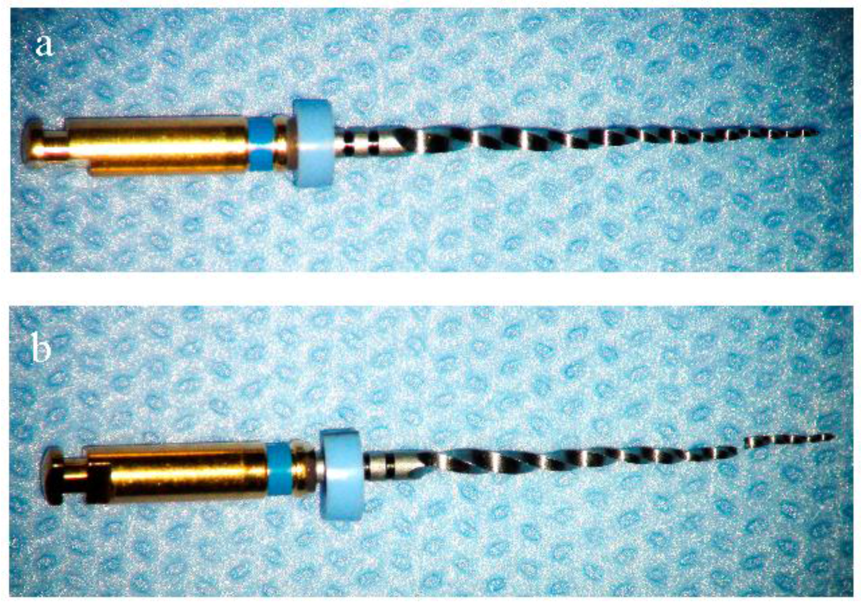
2. Materials and Methods
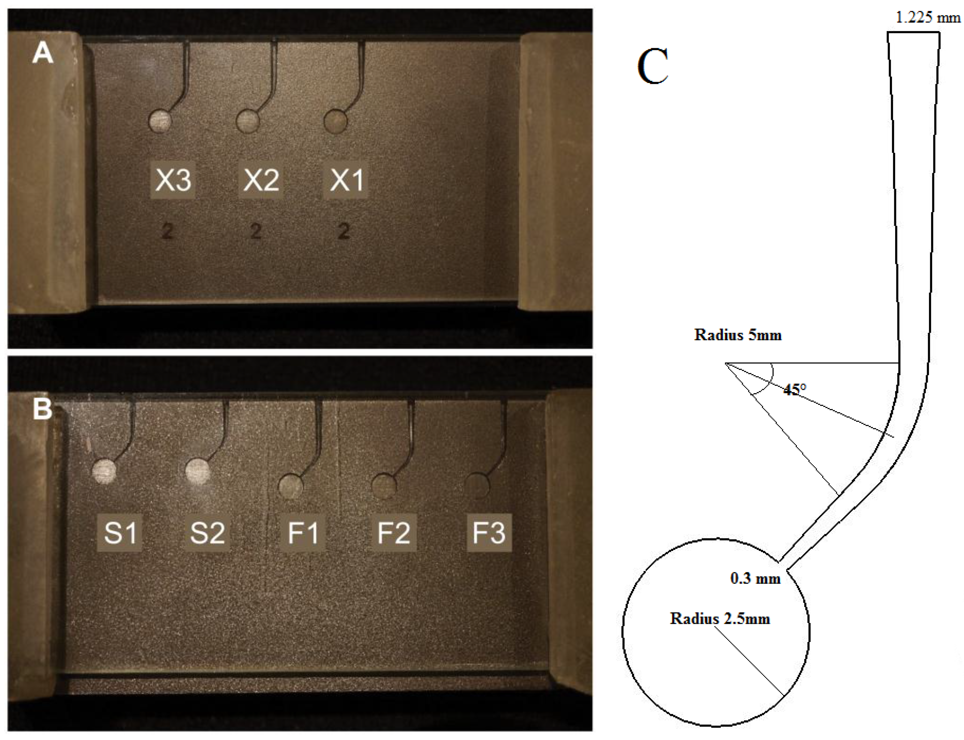
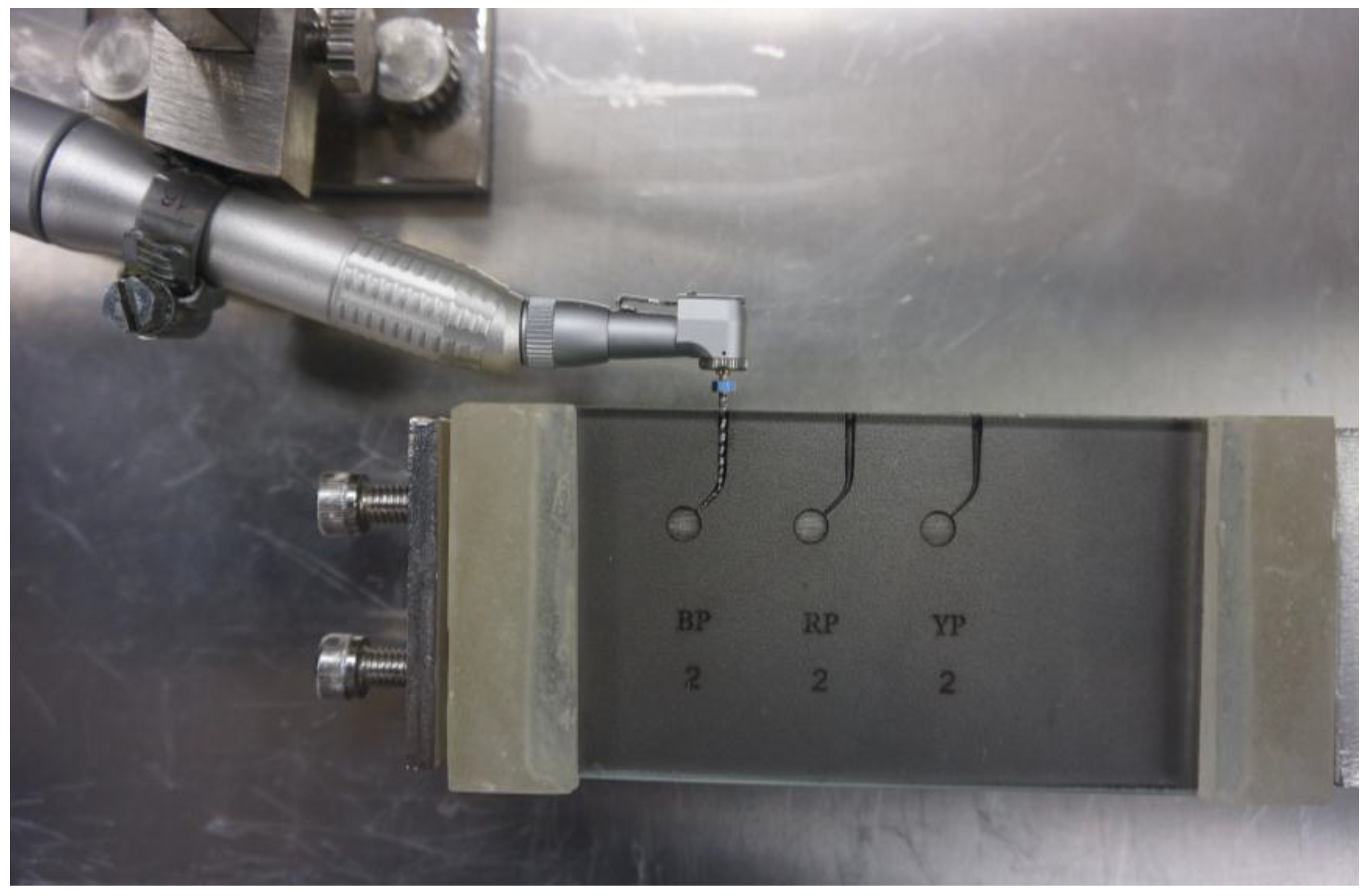
2.1. Preparation of Artificial Canals
2.2. Cyclic Fatigue Testing
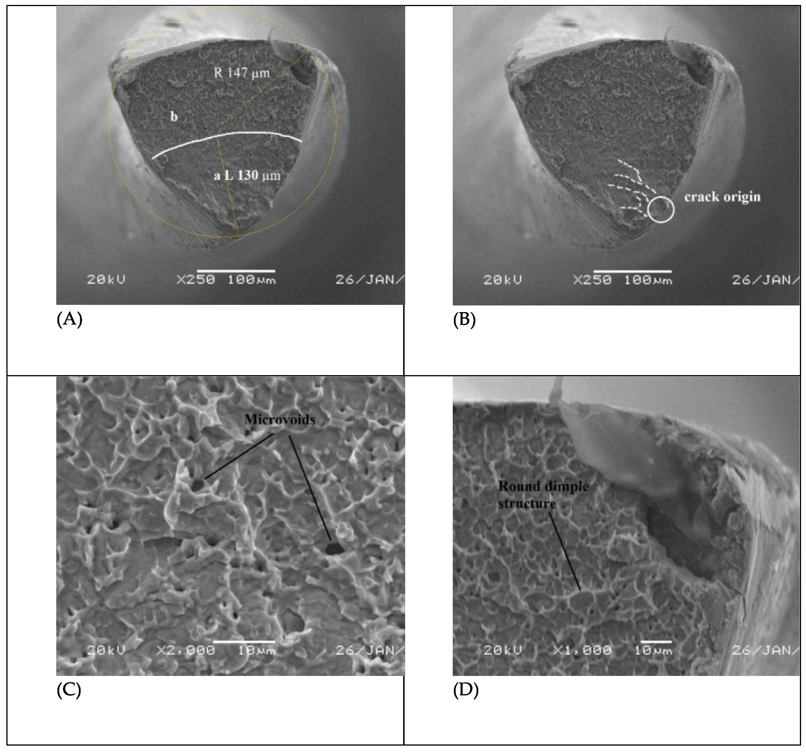
3. Results
4. Discussion
5. Conclusions
Acknowledgments
Author Contributions
Conflicts of Interest
References
- Walia, H.; Brantley, W.A.; Gerstein, H. An initial investigation of the bending and torsional properties of nitinol root canal files. J. Endod. 1988, 14, 346–351. [Google Scholar] [CrossRef]
- Hülsmann, M.; Peters, O.A.; Dummer, P.M.H. Mechanical preparation of root canals: Shaping goals, techniques and means. Endod. Top. 2005, 10, 30–76. [Google Scholar] [CrossRef]
- Peters, O.A. Current challenges and concepts in the preparation of root canal systems: A review. J. Endod. 2004, 30, 559–567. [Google Scholar] [CrossRef] [PubMed]
- Nitinol and Stainless Steel: Property Comparison. Available online: http://jmmedical.com/resources/231/Comparison-of-Properties-of-NiTi-and-Stainless-Steel.html (accessed on 28 December 2017).
- Elnaghy, A.M.; Elsaka, S.E. Assessment of the mechanical properties of protaper next nickel-titanium rotary files. J. Endod. 2014, 40, 1830–1834. [Google Scholar] [CrossRef] [PubMed]
- Pruett, J.P.; Clement, D.J.; Carnes, D.L., Jr. Cyclic fatigue testing of nickel-titanium endodontic instruments. J. Endod. 1997, 23, 77–85. [Google Scholar] [CrossRef]
- Hieawy, A.; Haapasalo, M.; Zhou, H.; Wang, Z.J.; Shen, Y. Phase transformation behavior and resistance to bending and cyclic fatigue of protaper gold and protaper universal instruments. J. Endod. 2015, 41, 1134–1138. [Google Scholar] [CrossRef] [PubMed]
- Plotino, G.; Grande, N.M.; Cordaro, M.; Testarelli, L.; Gambarini, G. A review of cyclic fatigue testing of nickel-titanium rotary instruments. J. Endod. 2009, 35, 1469–1476. [Google Scholar] [CrossRef] [PubMed]
- Shen, Y.; Zhou, H.M.; Zheng, Y.F.; Peng, B.; Haapasalo, M. Current challenges and concepts of the thermomechanical treatment of nickel-titanium instruments. J. Endod. 2013, 39, 163–172. [Google Scholar] [CrossRef] [PubMed]
- Haikel, Y.; Serfaty, R.; Bateman, G.; Senger, B.; Allemann, C. Dynamic and cyclic fatigue of engine-driven rotary nickel-titanium endodontic instruments. J. Endod. 1999, 25, 434–440. [Google Scholar] [CrossRef]
- Ruddle, C.J.; Machtou, P.; West, J.D. Endodontic canal preparation: Innovations in glide path management and shaping canals. Dent. Today 2014, 33, 118–123. [Google Scholar] [PubMed]
- Plotino, G.; Grande, N.M.; Sorci, E.; Malagnino, V.A.; Somma, F. A comparison of cyclic fatigue between used and new mtwo Ni-Ti rotary instruments. Int. Endod. J. 2006, 39, 716–723. [Google Scholar] [CrossRef] [PubMed]
- Plotino, G.; Grande, N.M.; Sorci, E.; Malagnino, V.A.; Somma, F. Influence of a brushing working motion on the fatigue life of NiTi rotary instruments. Int. Endod. J. 2007, 40, 45–51. [Google Scholar] [CrossRef] [PubMed]
- Gambarini, G.; Grande, N.M.; Plotino, G.; Somma, F.; Garala, M.; De Luca, M.; Testarelli, L. Fatigue resistance of engine-driven rotary nickel-titanium instruments produced by new manufacturing methods. J. Endod. 2008, 34, 1003–1005. [Google Scholar] [CrossRef] [PubMed]
- Mohammed, M.K.; Al-Ahmari, A.; Umer, U. Multiobjective optimization of Nd: YAG direct laser writing of microchannels for microfluidic applications. Int. J. Adv. Manuf. Technol. 2015, 81, 1363–1377. [Google Scholar] [CrossRef]
- Montgomery, D.C. Design and Analysis of Experiments; John Wiley & Sons: New York, NY, USA, 2017; ISBN 978-1-119-11347-8. [Google Scholar]
- De Oliveira Correia, J.A.F.; Pedrosa, B.A.S.; Raposo, P.C.; De Jesus, A.M.P.; dos Santos Gervásio, H.M.; Lesiuk, G.S.; da Silva Rebelo, C.A.; Calçada, R.A.B.; da Silva, L.A.P.S. Fatigue Strength Evaluation of Resin-Injected Bolted Connections Using Statistical Analysis. Engineering 2017. [Google Scholar] [CrossRef]
- Correia, J.A.F.O.; Blasón, S.; De Jesus, A.M.P.; Canteli, A.F.; Moreira, P.M.G.P.; Tavares, P.J. Fatigue life prediction based on an equivalent initial flaw size approach and a new normalized fatigue crack growth model. Eng. Fail. Anal. 2016, 69, 15–28. [Google Scholar] [CrossRef]
- Zhu, S.-P.; Huang, H.-Z.; Peng, W.; Wang, H.-K.; Mahadevan, S. Probabilistic Physics of Failure-based framework for fatigue life prediction of aircraft gas turbine discs under uncertainty. Reliab. Eng. Syst. Saf. 2016, 146, 1–12. [Google Scholar] [CrossRef]
- Zhu, S.P.; Liu, Q.; Lei, Q.; Wang, Q. Probabilistic fatigue life prediction and reliability assessment of a high pressure turbine disc considering load variations. Int. J. Damage Mech. 2017, 1056789517737132. [Google Scholar] [CrossRef]
- Zhu, S.P.; Huang, H.Z.; Li, Y.; Liu, Y.; Yang, Y. Probabilistic modeling of damage accumulation for time-dependent fatigue reliability analysis of railway axle steels. Proc. Inst. Mech. Eng. Part F J. Rail Rapid Transit 2015, 229, 23–33. [Google Scholar] [CrossRef]
- De Melo, M.C.C.; de Azevedo Bahia, M.G.; Buono, V.T.L. Fatigue resistance of engine-driven rotary nickel-titanium endodontic instruments. J. Endod. 2002, 28, 765–769. [Google Scholar]
- Cheung, G.S.; Darvell, B.W. Low-cycle fatigue of NiTi rotary instruments of various cross-sectional shapes. Int. Endod. J. 2007, 40, 626–632. [Google Scholar] [CrossRef] [PubMed]
- Ray, J.J.; Kirkpatrick, T.C.; Rutledge, R.E. Cyclic fatigue of endosequence and K3 rotary files in a dynamic model. J. Endod. 2007, 33, 1469–1472. [Google Scholar] [CrossRef] [PubMed]
- Tripi, T.R.; Bonaccorso, A.; Condorelli, G.G. Cyclic fatigue of different nickel-titanium endodontic rotary instruments. Oral Surg. Oral Med. Oral Pathol. Oral Radiol. Endod 2006, 102, e106–e114. [Google Scholar] [CrossRef] [PubMed]
- Cheung, G.S.; Zhang, E.W.; Zheng, Y.F. A numerical method for predicting the bending fatigue life of NiTi and stainless steel root canal instruments. Int. Endod. J. 2011, 44, 357–361. [Google Scholar] [CrossRef] [PubMed]
- Gao, Y.; Gutmann, J.L.; Wilkinson, K.; Maxwell, R.; Ammon, D. Evaluation of the impact of raw materials on the fatigue and mechanical properties of profile vortex rotary instruments. J. Endod. 2012, 38, 398–401. [Google Scholar] [CrossRef] [PubMed]
- Perez-Higueras, J.J.; Arias, A.; de la Macorra, J.C.; Peters, O.A. Differences in cyclic fatigue resistance between protaper next and protaper universal instruments at different levels. J. Endod. 2014, 40, 1477–1481. [Google Scholar] [CrossRef] [PubMed]
- Nguyen, H.H.; Fong, H.; Paranjpe, A.; Flake, N.M.; Johnson, J.D.; Peters, O.A. Evaluation of the resistance to cyclic fatigue among protaper next, protaper universal, and vortex blue rotary instruments. J. Endod. 2014, 40, 1190–1193. [Google Scholar] [CrossRef] [PubMed]
- Kitagawa, H.; Takahashi, S. Applicability of Fracture Mechanics to Very Small Cracks or the Cracks in the Early Stages. In Proceedings of the Second International Conference on Mechanical Behavior of Materials, American Society for Metals, Metals Park, OH, USA, 16–20 August 1976; p. 627. [Google Scholar]
- Correia, J.; De Jesus, A.; Fernández-Canteli, A.; Brighenti, R.; Moreira, P.; Calçada, R. A procedure to obtain the probabilistic kitagawa-takahashi diagram. UPB Sci. Bull. Ser. Mech. Eng. 2016, 78, 3–12. [Google Scholar]
- Maierhofer, J.; Gänser, H.-P.; Pippan, R. Modified Kitagawa–Takahashi diagram accounting for finite notch depths. Int. J. Fatigue 2015, 70, 503–509. [Google Scholar] [CrossRef]


| Properties | Ni–Ti Alloy | Stainless Steel |
|---|---|---|
| Ultimate tensile strength | ~1240 MPa | ~760 MPa |
| Density | 6.45 gm/cm3 | 8.03 gm/cm3 |
| Recoverable elongation | 8% | 0.8% |
| Effective modulus | ~48 GPa | ~193 GPa |
| Coefficient of thermal expansion | 6.6×10⁻⁶ – 11×10−6 °C−1 | 17.3×10⁻⁶ °C−1 |
| Micro-hardness | 303–362 VHN | 522–542 VHN |
| Active Part Length (mm) | Diameter (mm) | ||||
|---|---|---|---|---|---|
| S1 | S2 | F1 | F2 | F3 | |
| 0 | 0.170 | 0.200 | 0.200 | 0.250 | 0.300 |
| 1 | 0.190 | 0.240 | 0.270 | 0.330 | 0.390 |
| 2 | 0.220 | 0.285 | 0.340 | 0.410 | 0.480 |
| 3 | 0.260 | 0.335 | 0.410 | 0.490 | 0.570 |
| 4 | 0.305 | 0.390 | 0.465 | 0.550 | 0.640 |
| 5 | 0.355 | 0.450 | 0.520 | 0.610 | 0.710 |
| 6 | 0.415 | 0.510 | 0.575 | 0.665 | 0.760 |
| 7 | 0.485 | 0.570 | 0.630 | 0.720 | 0.810 |
| 8 | 0.565 | 0.630 | 0.685 | 0.775 | 0.860 |
| 9 | 0.655 | 0.690 | 0.740 | 0.830 | 0.910 |
| 10 | 0.755 | 0.760 | 0.795 | 0.885 | 0.960 |
| 11 | 0.855 | 0.850 | 0.850 | 0.940 | 1.010 |
| 12 | 0.960 | 0.955 | 0.905 | 0.995 | 1.060 |
| 13 | 1.075 | 1.070 | 0.960 | 1.050 | 1.110 |
| 14 | 1.185 | 1.185 | 1.015 | 1.105 | 1.160 |
| 15 | 1.070 | 1.160 | 1.210 | ||
| 16 | 1.125 | 1.215 | 1.260 | ||
| Active Part Length (mm) | Diameter (mm) | |||||
|---|---|---|---|---|---|---|
| X1 | X2 | X3 | ||||
| Actual | Maximum | Actual | Maximum | Actual | Maximum | |
| 16 | 1.16 | 1.26 | 1.2 | 1.3 | 1.2 | 1.34 |
| 13 | 0.98 | 1.06 | 1.11 | 1.15 | 1.09 | 1.14 |
| 9 | 0.7 | 0.76 | 0.84 | 1.06 | 0.89 | 1 |
| 6 | 0.49 | 0.534 | 0.63 | 0.7 | 0.71 | 0.78 |
| 3 | 0.31 | 0.35 | 0.43 | 0.45 | 0.53 | 0.65 |
| 1 | 0.21 | 0.23 | 0.31 | 0.34 | 0.38 | 0.52 |
| 0 | 0.17 | 0.17 | 0.25 | 0.25 | 0.3 | 0.3 |
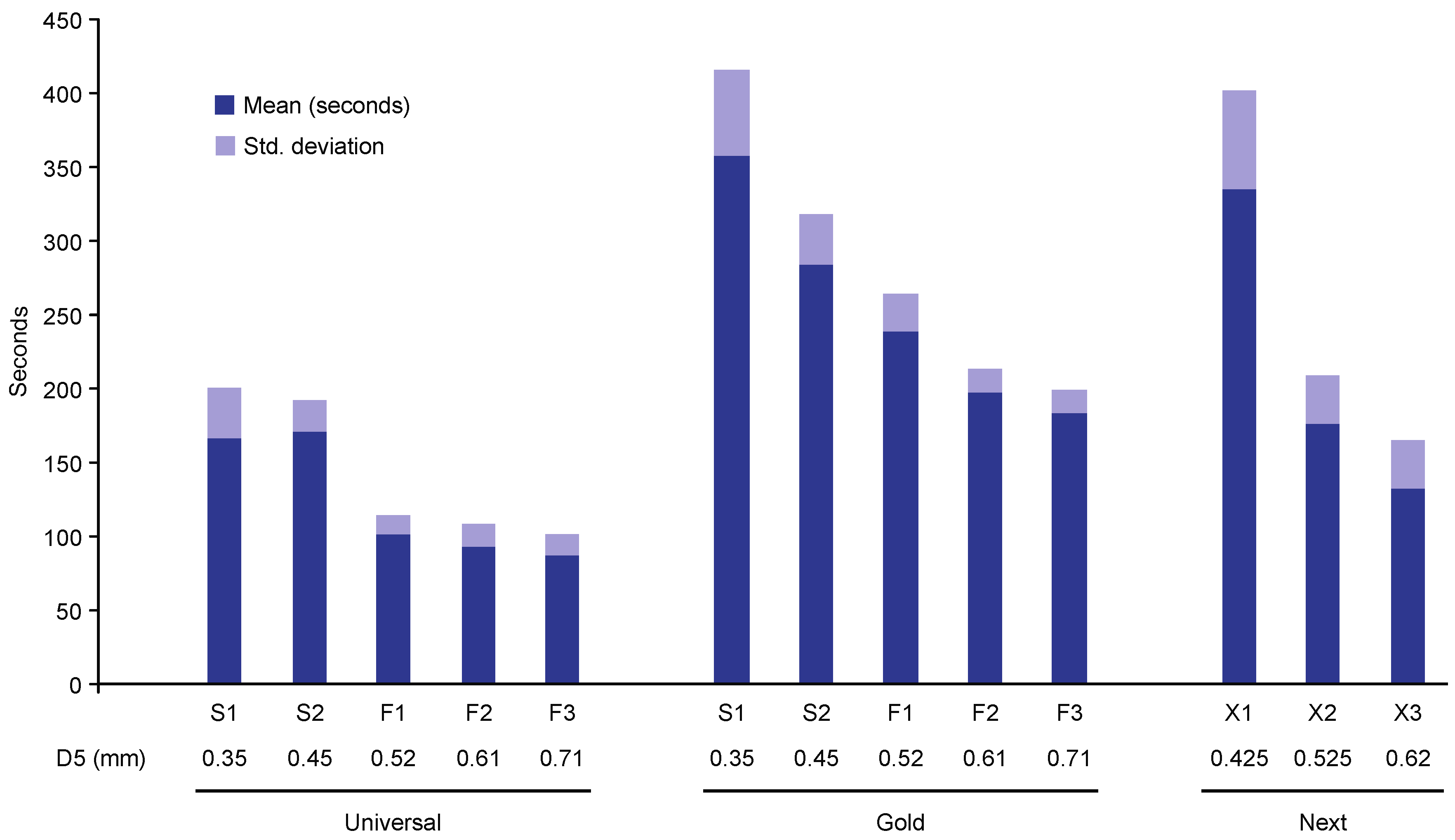
| Instrument | N | Mean ± SD | Weibull Modulus | R-Squared | Predicted Time in Seconds for 99% Survival |
|---|---|---|---|---|---|
| PTU | |||||
| S1 | 15 | 166.07 ± 34.3 | 4.809 | 0.914 | 69 |
| S2 | 15 | 170.40 ± 21.9 | 8.500 | 0.924 | 104 |
| F1 | 15 | 101.47 ± 13.6 | 8.528 | 0.986 | 62 |
| F2 | 15 | 93.20 ± 15.2 | 6.405 | 0.965 | 48 |
| F3 | 15 | 87.20 ± 13.8 | 6.338 | 0.918 | 44 |
| PTG | |||||
| S1 | 15 | 352.5 ± 57.4 | 6.357 | 0.916 | 181 |
| S2 | 15 | 294.0 ± 34.2 | 5.495 | 0.839 | 135 |
| F1 | 15 | 239.40 ± 25.4 | 9.276 | 0.952 | 152 |
| F2 | 15 | 198.40 ± 14.6 | 13.415 | 0.951 | 145 |
| F3 | 15 | 183.40 ± 16.6 | 10.352 | 0.872 | 122 |
| PTN | |||||
| X1 | 15 | 334.69 ± 67.5 | 5.062 | 0.865 | 154 |
| X2 | 15 | 176.93 ± 32.3 | 5.221 | 0.950 | 78 |
| X3 | 15 | 133.27 ± 31.5 | 4.274 | 0.781 | 49 |
© 2018 by the authors. Licensee MDPI, Basel, Switzerland. This article is an open access article distributed under the terms and conditions of the Creative Commons Attribution (CC BY) license (http://creativecommons.org/licenses/by/4.0/).
Share and Cite
Alqedairi, A.; Alfawaz, H.; Bin Rabba, A.; Almutairi, A.; Alnafaiy, S.; Khan Mohammed, M. Failure Analysis and Reliability of Ni–Ti-Based Dental Rotary Files Subjected to Cyclic Fatigue. Metals 2018, 8, 36. https://doi.org/10.3390/met8010036
Alqedairi A, Alfawaz H, Bin Rabba A, Almutairi A, Alnafaiy S, Khan Mohammed M. Failure Analysis and Reliability of Ni–Ti-Based Dental Rotary Files Subjected to Cyclic Fatigue. Metals. 2018; 8(1):36. https://doi.org/10.3390/met8010036
Chicago/Turabian StyleAlqedairi, Abdullah, Hussam Alfawaz, Amani Bin Rabba, Areej Almutairi, Sarah Alnafaiy, and Muneer Khan Mohammed. 2018. "Failure Analysis and Reliability of Ni–Ti-Based Dental Rotary Files Subjected to Cyclic Fatigue" Metals 8, no. 1: 36. https://doi.org/10.3390/met8010036
APA StyleAlqedairi, A., Alfawaz, H., Bin Rabba, A., Almutairi, A., Alnafaiy, S., & Khan Mohammed, M. (2018). Failure Analysis and Reliability of Ni–Ti-Based Dental Rotary Files Subjected to Cyclic Fatigue. Metals, 8(1), 36. https://doi.org/10.3390/met8010036