Dependence of Creep Performance and Microstructure Evolution on Solution Cooling Rate in a Polycrystalline Superalloy

Abstract
:1. Introduction
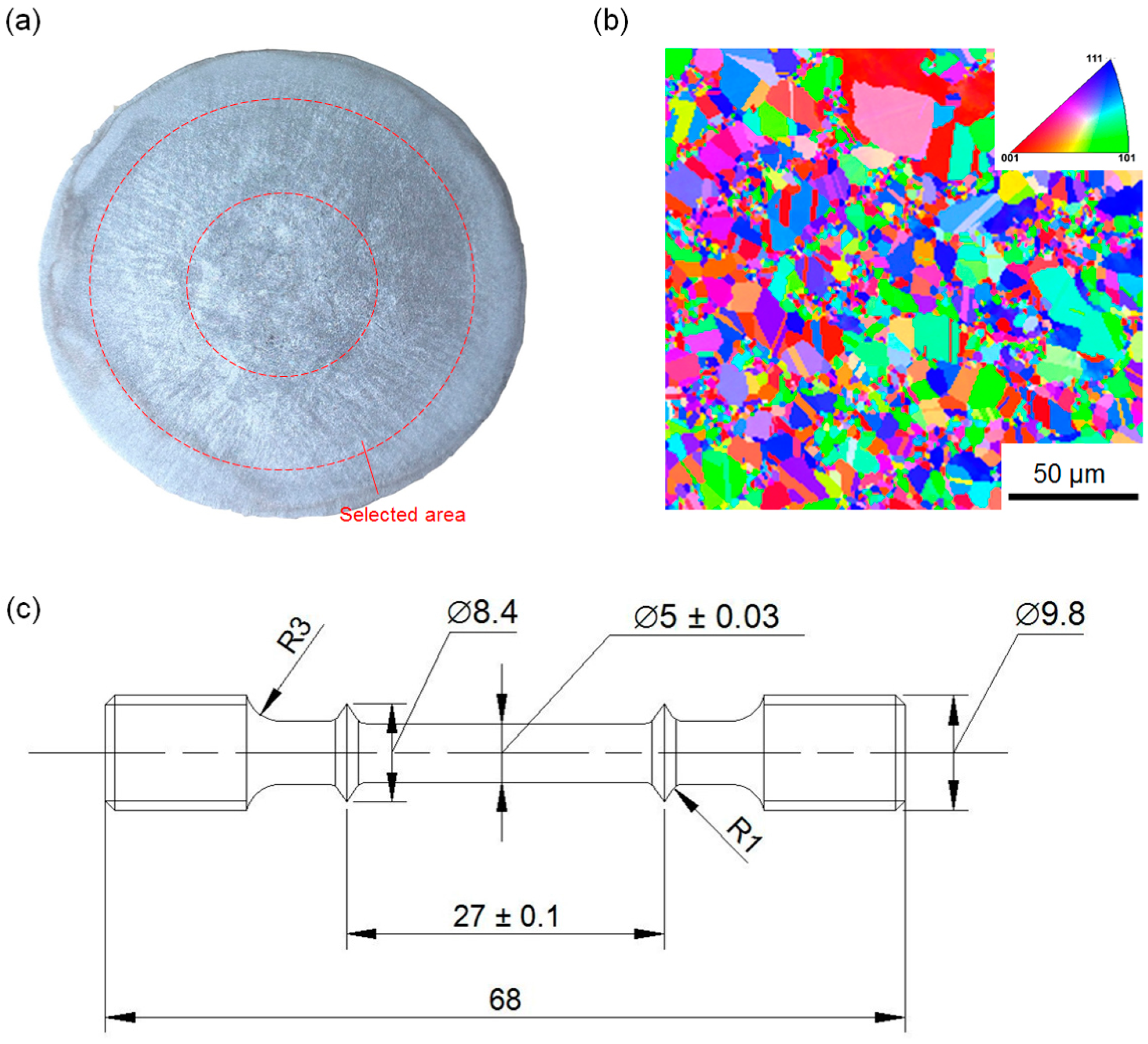
2. Experimental Procedures
3. Results and Discussions
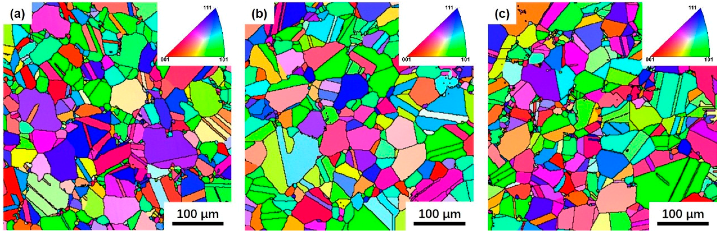
3.1. Microstructure
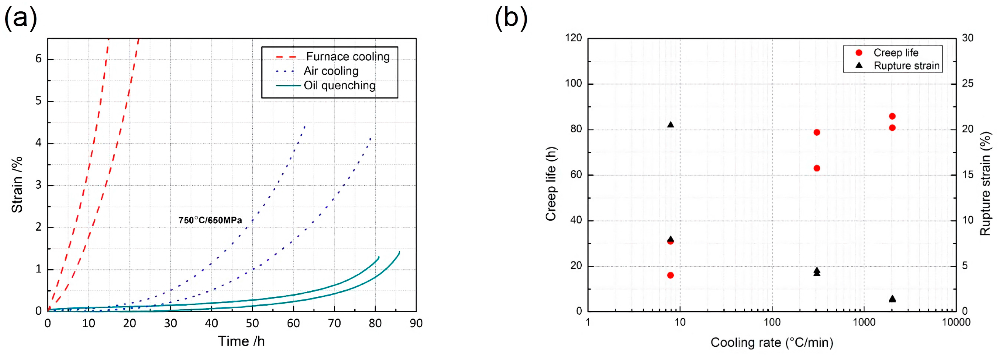
3.2. Creep Results
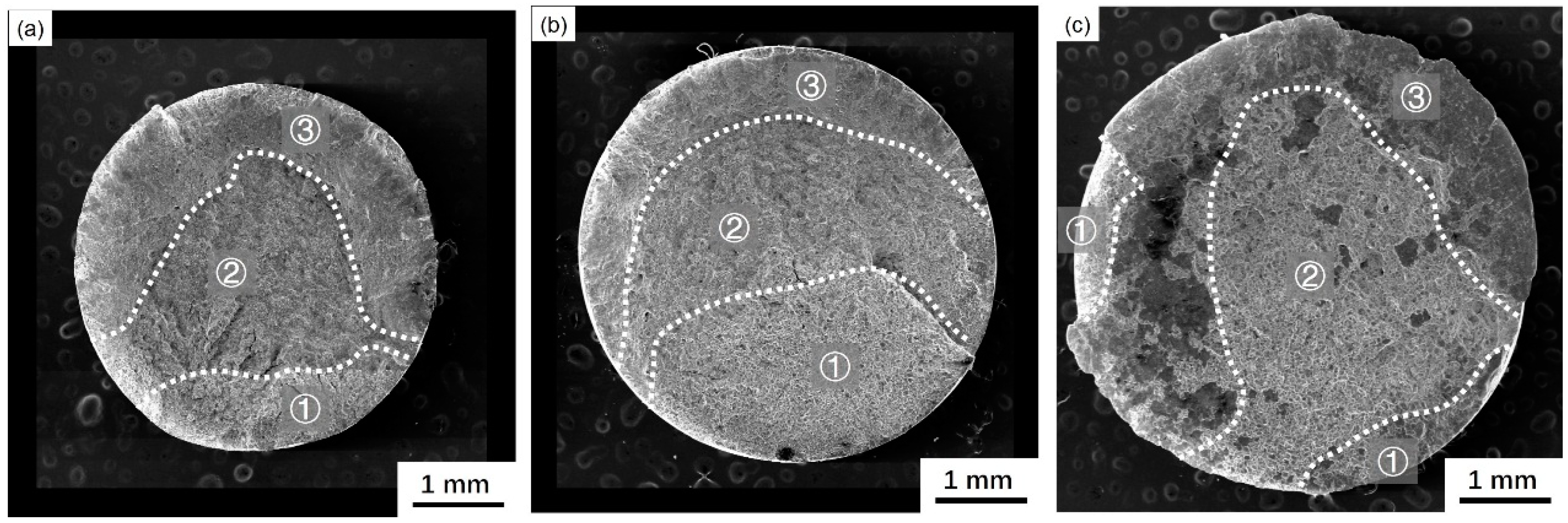
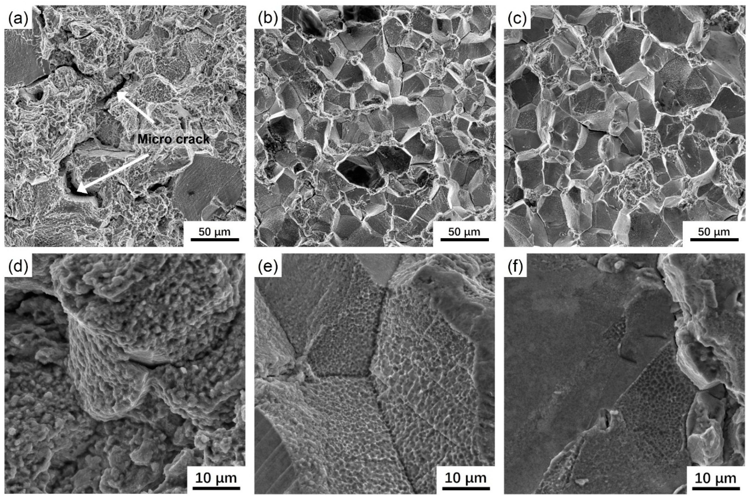
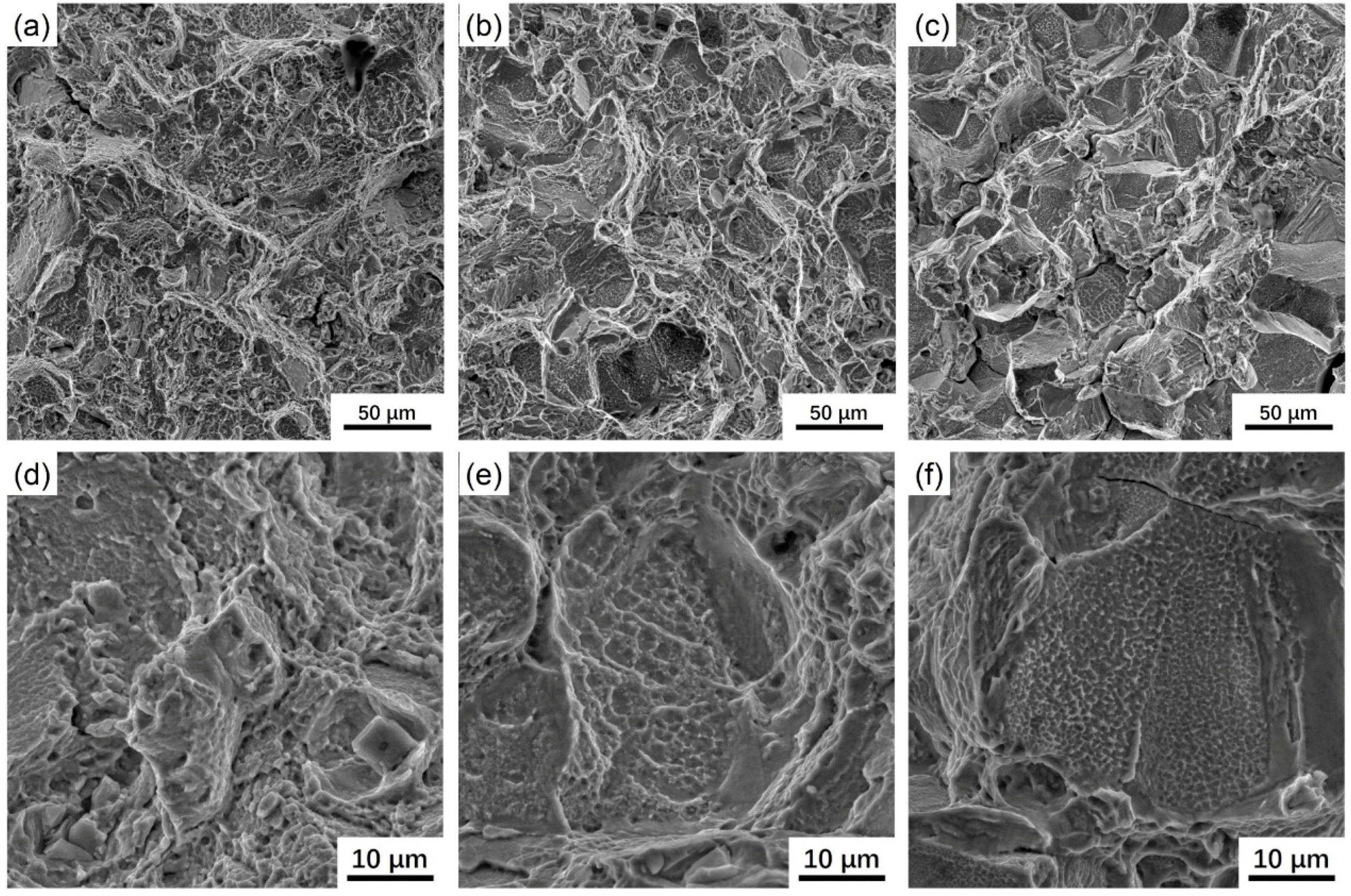
3.3. Fracture Morphology
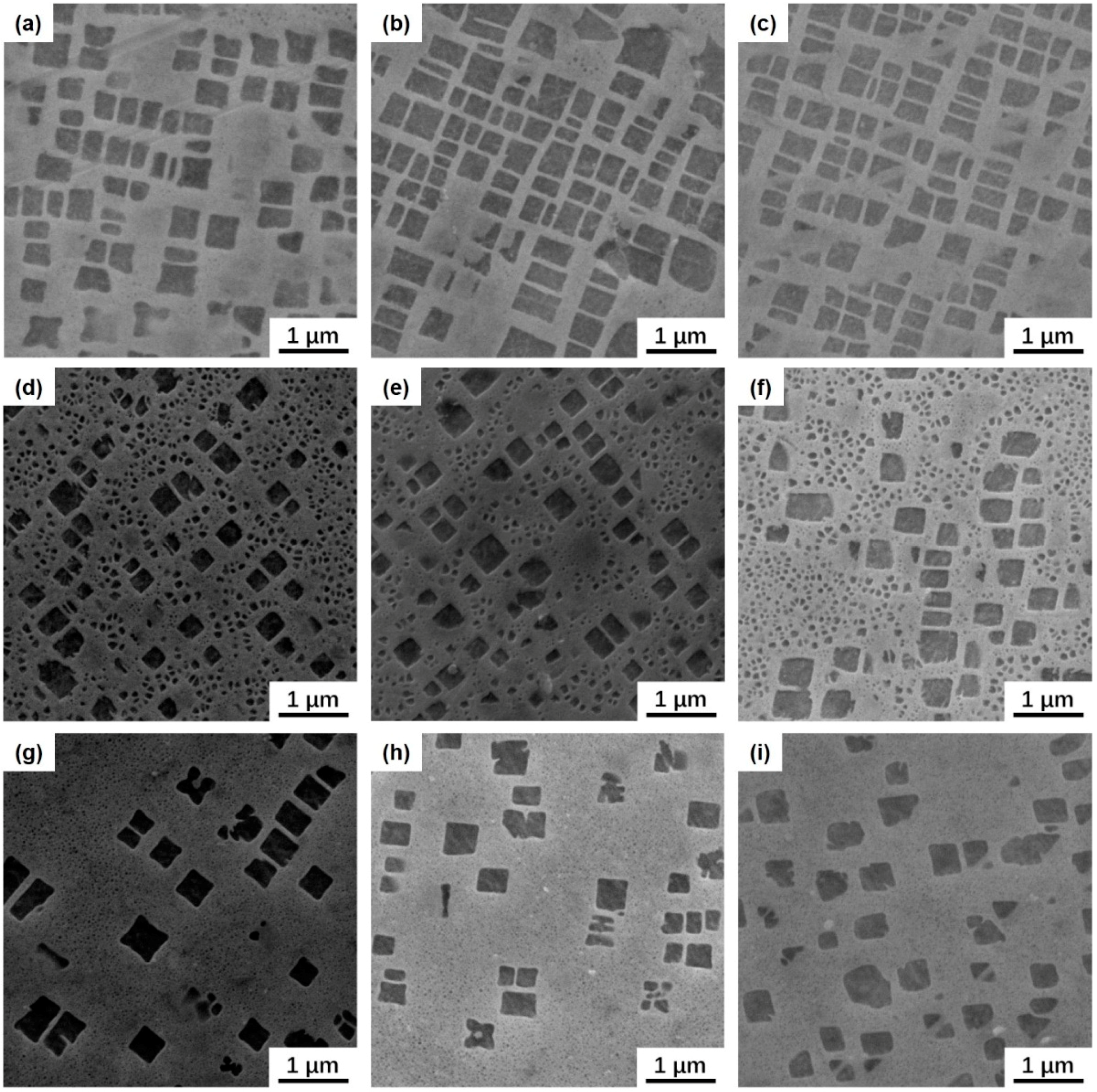
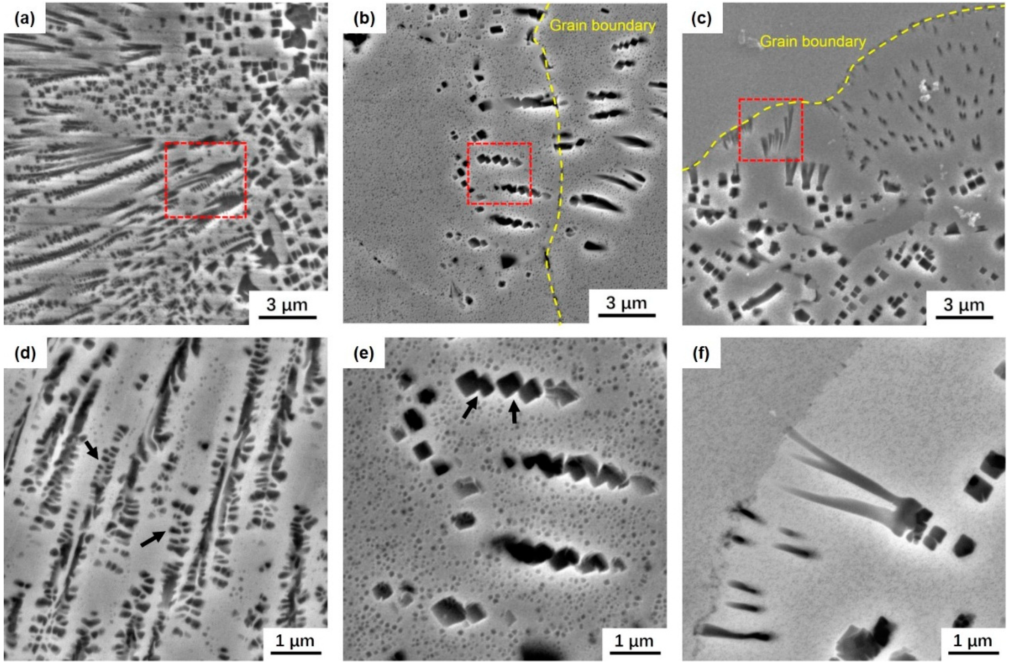
3.4. Microstructure after the Creep
4. Conclusions
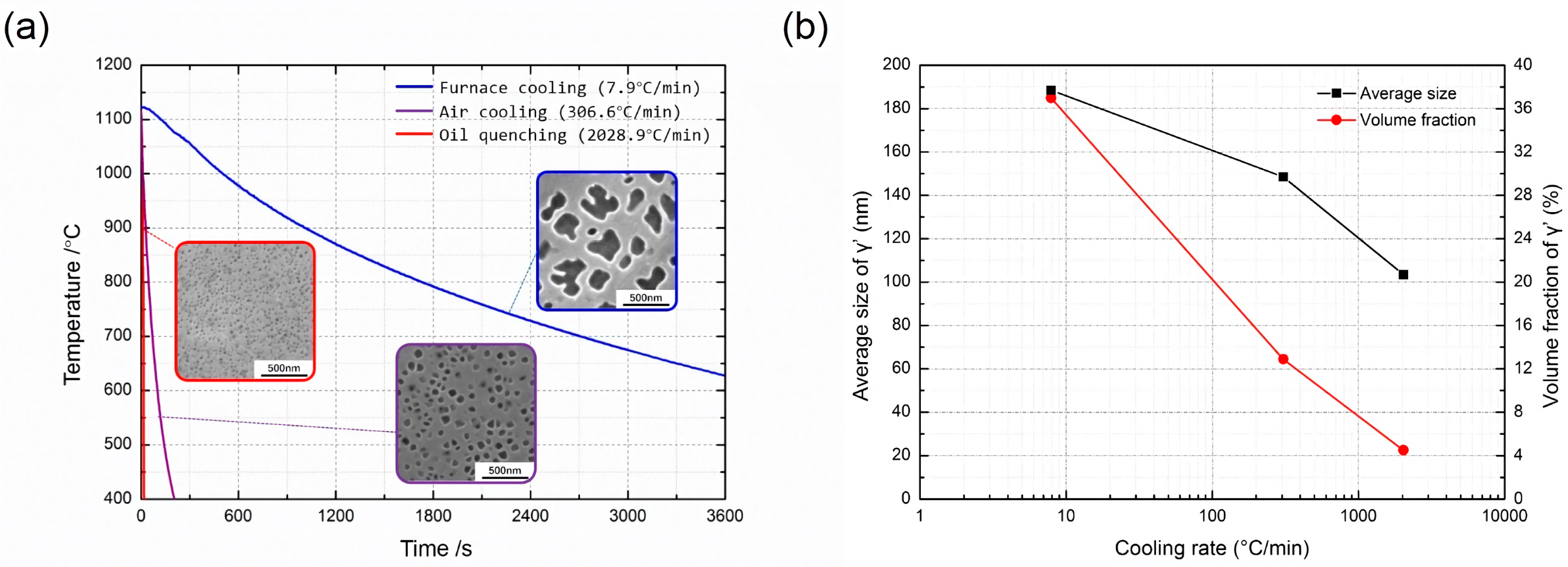
- The cooling rate of furnace cooling, air cooling and oil quenching is measured to be 8 °C/min, 307 °C/min and 2029 °C/min, respectively. With increasing cooling rates, γ’ size changed from 185 nm to 22.5 nm, the area fraction of γ’ changed from 37.7% to 20.7%, but the grain size remained at about 12 μm.
- The data of the creep test at 750 °C/650 MPa shows that for the furnace cooling, air cooling, and oil quenching specimens, the mean creep life is 23.45 h, 70.9 h, 83.35 h, respectively. The creep life of the oil quenching specimen is three times longer than that of the furnace cooling specimen. Deformation mechanisms may change from Orowan looping to γ’ shearing as the cooling rates increased. It seems that oil quenching is the best solution cooling mode for the experiment alloy.
- The rupture mechanism changed from transgranular for the furnace cooling specimen to intergranular for the oil quenching specimen. After the creep test, some γ’ precipitates changed to cuboid, and aligned similarly to the rafted structure which is usually observed in single crystal superalloys. Other special γ’ merging morphologies were also found. The reason remains to be investigated.
Acknowledgments
Author Contributions
Conflicts of Interest
References
- Pollock, T.M.; Tin, S. Nickel-based superalloys for advanced turbine engines: Chemistry, microstructure, and properties. J. Propuls. Power 2006, 22, 361–374. [Google Scholar] [CrossRef]
- Schafrik, R.; Sprague, R. Saga of gas turbine materials. Part IV. Adv. Mater. Process. 2004, 162, 41–46. [Google Scholar]
- Reed, R.C. The Superalloys: Fundamentals and Applications; Cambridge University Press: Cambridge, UK, 2008. [Google Scholar]
- Zhang, M.; Li, F.; Yuan, Z.; Li, J.; Wang, S. Effect of heat treatment on the micro-indentation behavior of powder metallurgy nickel based superalloy FGH96. Mater. Des. 2013, 49, 705–715. [Google Scholar] [CrossRef]
- Sims, C.T.; Stoloff, N.S.; Hagel, W.C. Superalloys II; Wiley: New York, NY, USA, 1987. [Google Scholar]
- Torster, F.; Baumeister, G.; Albrecht, J.; Lütjering, G.; Helm, D.; Daeubler, M. Influence of grainsize and heat treatment on the microstructures and mechanical properties of the nickel-base superalloy U720Li. Mater. Sci. Eng. A 1997, 234, 189–192. [Google Scholar] [CrossRef]
- Wei, C.; Bor, H.; Ma, C.; Lee, T. A study of IN-713LC superalloy grain refinement effects on microstructure and tensile properties. Mater. Chem. Phys. 2003, 80, 89–93. [Google Scholar] [CrossRef]
- Caron, P.; Khan, T. Improvement of creep strength in a nickel-base single-crystal superalloy by heat treatment. Mater. Sci. Eng. 1983, 61, 173–184. [Google Scholar] [CrossRef]
- Sajjadi, S.A.; Elahifar, H.; Farhangi, H. Effects of cooling rate on the microstructure and mechanical properties of the Ni-base superalloy UDIMET 500. J. Alloys Compd. 2008, 455, 215–220. [Google Scholar] [CrossRef]
- Khan, T.; Caron, P. Effect of processing conditions and heat treatments on mechanical properties of single-crystal superalloy CMSX-2. Mater. Sci. Technol. 1986, 2, 486–492. [Google Scholar] [CrossRef]
- Safari, J.; Nategh, S. On the heat treatment of Rene-80 nickel-base superalloy. J. Mater. Process. Technol. 2006, 176, 240–250. [Google Scholar] [CrossRef]
- Singh, A.; Nag, S.; Hwang, J.; Viswanathan, G.; Tiley, J.; Srinivasan, R.; Fraser, H.; Banerjee, R. Influence of cooling rate on the development of multiple generations of γ′ precipitates in a commercial nickel base superalloy. Mater. Charact. 2011, 62, 878–886. [Google Scholar] [CrossRef]
- Bhowal, P.; Wright, E.; Raymond, E. Effects of cooling rate and γ′ morphology on creep and stress-rupture properties of a powder metallurgy superalloy. Metall. Trans. A 1990, 21, 1709–1717. [Google Scholar] [CrossRef]
- Viswanathan, G.; Sarosi, P.; Henry, M.; Whitis, D.; Mills, M. Deformation Mechanisms at Intermediate Creep Temperatures in Rene 88DT. Superalloys 2004, 2004, 173–178. [Google Scholar]
- Kakehi, K. Effect of primary and secondary precipitates on creep strength of Ni-base superalloy single crystals. Mater. Sci. Eng. A 2000, 278, 135–141. [Google Scholar] [CrossRef]
- Laurence, A.; Cormier, J.; Villechaise, P.; Billot, T.; Franchet, J.-M.; Pettinari-Sturmel, F.; Hantcherli, M.; Mompiou, F.; Wessman, A. Impact of the Solution Cooling Rate and of Thermal Aging on the Creep Properties of the New Cast & Wrought René 65 Ni-Based Superalloy. In Proceedings of the 8th International Symposium on Superalloy 718 and Derivative, Marriott Pittsburh City Center, Pittsburgh, PA, USA, 28 September–1 October 2014; John Wiley & Sons: Hoboken, NJ, USA, 2014; p. 33. [Google Scholar]
- Goff, S.D.; Couturier, R.; Guétaz, L.; Burlet, H. Effect of the microstructure on the creep behavior of PM Udimet 720 superalloy—Experiments and modeling. Mater. Sci. Eng. A 2004, 387, 599–603. [Google Scholar] [CrossRef]
- Brown, L.M.; Ham, R.K. Strengthening Mechanisms in Crystals; Kelly, A., Nicholson, R.B., Eds.; Elsevier: Amsterdam, The Netherlands, 1971; pp. 9–135. [Google Scholar]
- Coakley, J.; Basoalto, H.; Dye, D. Coarsening of a multimodal nickel-base superalloy. Acta Mater. 2010, 58, 4019–4028. [Google Scholar] [CrossRef]
- Chiou, M.-S.; Jian, S.-R.; Yeh, A.-C.; Kuo, C.-M.; Juang, J.-Y. High temperature creep properties of directionally solidified CM-247LC Ni-based superalloy. Mater. Sci. Eng. A 2016, 655, 237–243. [Google Scholar] [CrossRef]
- Bauer, A.; Neumeier, S.; Pyczak, F.; Singer, R.; Göken, M. Creep properties of different γ′-strengthened Co-base superalloys. Mater. Sci. Eng. A 2012, 550, 333–341. [Google Scholar] [CrossRef]
- Altincekic, A.; Balikci, E. Precipitate rafting in a polycrystalline superalloy during compression creep. Metall. Mater. Trans. A 2014, 45, 5923–5936. [Google Scholar] [CrossRef]
- Murakumo, T.; Kobayashi, T.; Koizumi, Y.; Harada, H. Creep behavior of Ni-base single-crystal superalloys with various γ′ volume fraction. Acta Mater. 2004, 52, 3737–3744. [Google Scholar] [CrossRef]
- Ges, A.; Fornaro, O.; Palacio, H. Coarsening behaviour of a Ni-base superalloy under different heat treatment conditions. Mater. Sci. Eng. A 2007, 458, 96–100. [Google Scholar] [CrossRef]


| Cr | Co | W | Mo | Ti | Al | Nb | Fe | Zr | C | B | Ni |
|---|---|---|---|---|---|---|---|---|---|---|---|
| 15.84 | 12.59 | 3.98 | 3.94 | 3.73 | 2.09 | 0.8 | 0.093 | 0.037 | 0.038 | 0.012 | Bal. |
| Cooling Mode | rs/nm | ls/nm | τ0/MPa |
|---|---|---|---|
| Furnace Cooling | 75.5 | 67 | 281.9 |
| Air Cooling | 26.3 | 33 | 478 |
| Oil Quenching | 9.2 | 17.4 | 726.5 |
© 2017 by the authors. Licensee MDPI, Basel, Switzerland. This article is an open access article distributed under the terms and conditions of the Creative Commons Attribution (CC BY) license (http://creativecommons.org/licenses/by/4.0/).
Share and Cite
Xu, C.; Liu, F.; Huang, L.; Jiang, L. Dependence of Creep Performance and Microstructure Evolution on Solution Cooling Rate in a Polycrystalline Superalloy. Metals 2018, 8, 4. https://doi.org/10.3390/met8010004
Xu C, Liu F, Huang L, Jiang L. Dependence of Creep Performance and Microstructure Evolution on Solution Cooling Rate in a Polycrystalline Superalloy. Metals. 2018; 8(1):4. https://doi.org/10.3390/met8010004
Chicago/Turabian StyleXu, Chao, Feng Liu, Lan Huang, and Liang Jiang. 2018. "Dependence of Creep Performance and Microstructure Evolution on Solution Cooling Rate in a Polycrystalline Superalloy" Metals 8, no. 1: 4. https://doi.org/10.3390/met8010004
APA StyleXu, C., Liu, F., Huang, L., & Jiang, L. (2018). Dependence of Creep Performance and Microstructure Evolution on Solution Cooling Rate in a Polycrystalline Superalloy. Metals, 8(1), 4. https://doi.org/10.3390/met8010004