Article

A Unified Physical Model for Creep and Hot Working of Al-Mg Solid Solution Alloys

by
Stefano Spigarelli
* and
Chiara Paoletti
DIISM, Università Politecnica delle Marche, via Brecce Bianche, 60131 Ancona, Italy
*
Author to whom correspondence should be addressed.
Metals 2018, 8(1), 9; https://doi.org/10.3390/met8010009
Submission received: 27 November 2017 / Revised: 19 December 2017 / Accepted: 22 December 2017 / Published: 27 December 2017
(This article belongs to the Special Issue Light Weight Alloys: Processing, Properties and Their Applications)

Abstract

:
The description of the dependence of steady-state creep rate on applied stress and temperature is almost invariably based on the Norton equation or on derived power-law relationships. In hot working, the Norton equation does not work, and is therefore usually replaced with the Garofalo (sinh) equation. Both of these equations are phenomenological in nature and can be seldom unambiguously related to microstructural parameters, such as dislocation density, although early efforts in this sense led to the introduction of the “natural power law” with exponent 3. In an attempt to overcome this deficiency, a recent model with sound physical basis has been successfully used to describe the creep response of fcc metals, such as copper. The main advantage of this model is that it does not require any data fitting to predict the strain rate dependence on applied stress and temperature, which is a particularly attractive peculiarity when studying the hot workability of metals. Thus, the model, properly modified to take into account solid solution strengthening effects, has been here applied to the study of the creep and hot-working of simple Al-Mg single phase alloys. The model demonstrated an excellent accuracy in describing both creep and hot working regimes, still maintaining its most important feature, that is, it does not require any fitting of the experimental data.

1. Introduction

Although single-phase Al-Mg alloys have limited industrial relevance as creep-resistant alloys, their creep response has been analysed in many papers. A non-exhaustive picture of the extensive coverage of creep of Al-Mg alloys can be obtained, for example, from the relevant chapters in [1,2,3]. The cause for this interest can be traced back to the simple nature of these materials, since their microstructure constitutes a good case study to identify the main creep mechanisms and separate their relative contributions to creep response in solid solutions.
In most cases, the secondary creep rate ( ε ˙ ) dependence on applied stress (σ) and the temperature (T) of single-phase alloys has been described by the conventional power-law and Arrhenius equations, in the form
ε ˙ = A D 0 G b k T ( σ G ) n exp ( Q R T )
where A is a material parameter, k is the Boltzmann constant, G is the shear modulus, b is the length of the Burgers vector, and R is the gas constant (all the symbols used, and, where relevant, their values, are listed in Table 1). D0 in Equation (1) is the pre-exponential factor in the Arrhenius form and Q is the activation energy for the relevant diffusional mechanism (self-diffusion or diffusion of Mg atoms in Al). In pure Aluminium the stress exponent n is close to 4.4–5; however, above a certain stress level, power-law breakdown occurs, and the slope of the curve describing the strain rate dependence on applied stress in double-log coordinates increases progressively with the stress level applied. This behaviour, which is associated to a stress exponent in the power-law regime close to 5 and an activation energy equivalent to that for vacancy diffusion, identifies “class M” (Metal) materials. The addition of Mg results in a more complex dependence of the secondary creep rate on applied stress. The stress exponent in the low stress regime is close to 4–5, it then becomes 3 in an intermediate stress range, and again, 4–5 before power-law breakdown [4,5,6]. This behaviour (“class A”) is generally interpreted by invoking the fact that, since glide and climb of dislocations occur in sequence during high-temperature deformation, the slower is rate controlling. In pure metals, glide is always faster than climb; therefore, the latter is, without exceptions, the rate controlling mechanism. In class A materials, glide is substantially slowed down by the formation of clouds of solute atoms around dislocations, and is, consequently, the rate controlling factor in the intermediate stress regime, leading to n = 3 and to an activation energy that is equivalent to the activation energy for diffusion of Mg atoms in Al. It is only when climb is very slow (in the low stress regime) or when the solute atoms no longer play any role, since dislocations have broken away from their atmospheres (in high stress regime), that the stress exponent is 4–5 and a class-M behaviour is apparent.
The explanation of the phenomenology of creep in Al-Mg alloys, which are very synthetically outlined above, and the use of power law to describe related experimental data are generally taken for granted. Yet, the power law is phenomenological in nature, and, for this reason, alternative approaches have been sought to introduce a set of constitutive equations more directly, based on the underlying physics. The recent work by Fernández and González-Doncel [7], which deals with a unified model for the description of creep in Al-Mg alloy, is just one of the many examples. In this line of thought, Sandström proposed another set of equations for fcc metals, which, in his intent, should not require any best-fitting of experimental creep or mechanical data, being based only on a number of physical and microstructural pre-determined parameters [8,9]. The resulting basic model was developed to describe creep phenomena, but has been also successfully applied to high temperature constant strain rate experiments [8]. Since the analysis of the hot-working response of metals is based on compression or torsion constant-strain rate experiments, the use of Sandström’s set of equations to predict the material behaviour in this envelope of experimental conditions seems to be a straightforward step. This reasoning has led the authors of this paper to apply the basic model to Al-Mg single-phase alloys, with a major emphasis on the description of the high-temperature conditions typical of hot-working operations.

2. The Model

The model, originally developed for Cu, is based on physically-derived equations, which will be here illustrated for a simple Al alloy, possibly containing elements in solid solution.
Free dislocation density (ρ) [10] is usually related to applied stress by the well-known Taylor equation, written in the form
σ = σ i + σ s s + σ d = σ i + σ s s + α m G b ρ
where m is the Taylor factor and σ d = α m G b ρ 1 / 2 is the dislocation hardening term. The term σi represents the strength of pure annealed metal, that is, the stress that is required to move a dislocation in the absence of other dislocations, while α is a constant. In solid solution alloys, the viscous drag of dislocations is thought to reduce dislocation mobility and control creep response in a wide interval of applied stresses. The term σss thus represents the stress required for dislocations to move by viscous drag in the presence of solute atom atmospheres.
The evolution of dislocation density during straining can be expressed as [9]
d ρ d ε = m b L ω ρ 2 ε ˙ M τ l ρ 2
where ω is a constant, τ l is the dislocation line tension ( τ l = 0.5Gb2), M is the dislocation mobility, and L is the dislocation mean free path, i.e., the distance travelled by a dislocation before it undergoes a reaction, customarily expressed as
L = C L ρ
CL being the strain-hardening constant. The first term on the right-hand side of Equation (3) represents the strain hardening effect due to dislocation multiplication, which is more rapid when L, and, consequently, CL assume low values and/or the dislocation density is high. The second and third terms on the right-hand side of Equation (3) describe the effect of dynamic recovery. Since, at high temperature, the last term of Equation (3), which includes an Arrhenius-type dependence on T, largely predominates on the second term, which is roughly a-thermal, and the main emphasis in this study is on describing high-temperature behaviour (T > 500 K), Equation (3) can be simplified to become
d ρ d ε = m b L 2 ε ˙ M τ l ρ 2
The dislocation climb mobility in a pure metal, according to Hirth and Lothe [11], is
M c = D 0 s d b k T exp ( σ d b 3 k T ) exp ( Q s d R T )
To describe the creep results obtained in the high strain rate regime, which are characterised by higher stress exponents and lower values of the activation energy for creep, the model has been further modified to take into account another mechanism, the glide of dislocations through an obstacle field [12]. Thus, the glide mobility was described by a phenomenological equation in the form
M g exp { Q g R T [ 1 ( σ d R max ) p ] q }
where Rmax, which depends on material structure, is the flow stress that is required to plastically deform the material in the absence of thermal activation and Qg is the activation energy necessary to overcome the obstacle field. Recent studies [9,13] showed that Equation (7) works very well for pure Cu and Al with p = 2 and q = 1, with Rmax equivalent to the true stress corresponding to the ultimate tensile strength of the material considered, roughly quantified as 1.5Ruts, where Ruts is the ultimate tensile strength.
During viscous glide in solid solution alloys, solute atoms have to jump in and out of the atmospheres that spontaneously form around dislocations. Thus, an additional term describing the energy needed to overcome this barrier must be added to the activation energy. This additional term has the form [14]
U s s = β R b k
with
β = 1 3 π ( 1 + ν ) ( 1 ν ) b G Ω δ M g
where ν is the Poisson’s ratio (=0.3 in Al), Ω is the average Al-atomic volume, and δMg is the volume atomic misfit (details about Ω and δMg are given in [14]).
The combination of Equations (5)–(8) [9,13,14] gives the following relationship for climb and glide mobility, to be used for M into Equation (5):
M = M c g D 0 c g b k T exp [ σ d b 3 k T ] exp { Q c g R T [ 1 ( σ d R max ) 2 ] } exp ( U s s R T )
where Dcg = D0cgexp(−Qcg/RT) is the appropriate diffusion coefficient.
At steady state, Equation (5), combined with Equations (2) and (4), gives
ε ˙ s s = 2 M c g τ l b C L m ( σ d α m G b ) 3
The model based on Equations (9) and (10) requires the determination of CL (CL = 86 in pure Al [13]) and of two of the terms in Equation (2), namely σ i and σ s s .
In the case of pure Al, the determination of σi, which is temperature and strain rate dependent, was based on the assumption that the dislocation density in annealed state (ρa) and the σ i values account for the annealed yield strength of the pure metal [15]. The yield stress is thus given by Equation (2) (which is general, and holds for any single stage of the stress vs. strain curve) [15], where ρa is virtually nihil. The traditional way of describing the temperature dependence of yield strength is to assume that, in the creep range, yield strength is proportional to creep strength, whereas below the creep range yield strength is proportional to shear modulus. On these bases, for pure Al, the following expression has been used in [13]
σ i = A y σ c r e e p G
where σ c r e e p is the creep stress that corresponds to a given steady-state creep rate. The Ay constant (Ay = 4.2 × 10⁻³ [13]) was determined so as to obtain a reliable estimate of the yield strength of high-purity Al at room temperature by Equation (2).
An equation for solid solution strengthening stress was given in [14], in the form
σ s s = v d c β 2 b Ω D M g k T I ( z 0 )
where vd is the dislocation velocity, being c the Mg atomic concentration. The term DMg = D0Mg exp(−QMg/RT) is the diffusivity of Mg in Al. The term I(z0) can be calculated by the numerical integration of
I ( z 0 ) = 1 z 0 2 2 π 3 z 5 / 2 exp ( z ) d z
with z 0 = β / b k T [14].

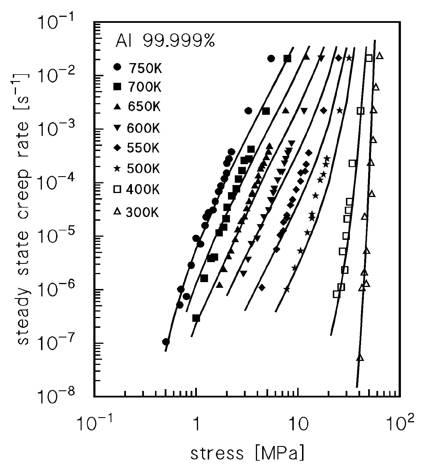
3. Description of High Purity Aluminium

Figure 1 plots the steady-state creep rate as a function of stress for Al 99.999% [16] and the model curves given by Equations (10) and (11) with CL = 86, Uss = 0, Qcg = Qsd = 122 kJ·mol−1, and Dcg = D0sd = 8.34 × 10⁻⁶ m2·s−1 [13]. The original Figure in [13] was obtained by taking ω = 15; in this study, the value ω = 0 was used, which demonstrates that the simplified model of Equation (5) still works very well. The diffusion coefficient was recalculated in [13] by considering all the data reported in [17]. The basic model gives a very good description of the experimental data for the pure metal, without any need for data fitting, and, for this reason, it is an excellent basis for the implementation of the analysis of Al-Mg alloys.

4. Description of High Purity Aluminium-Magnesium Single Phase Alloys

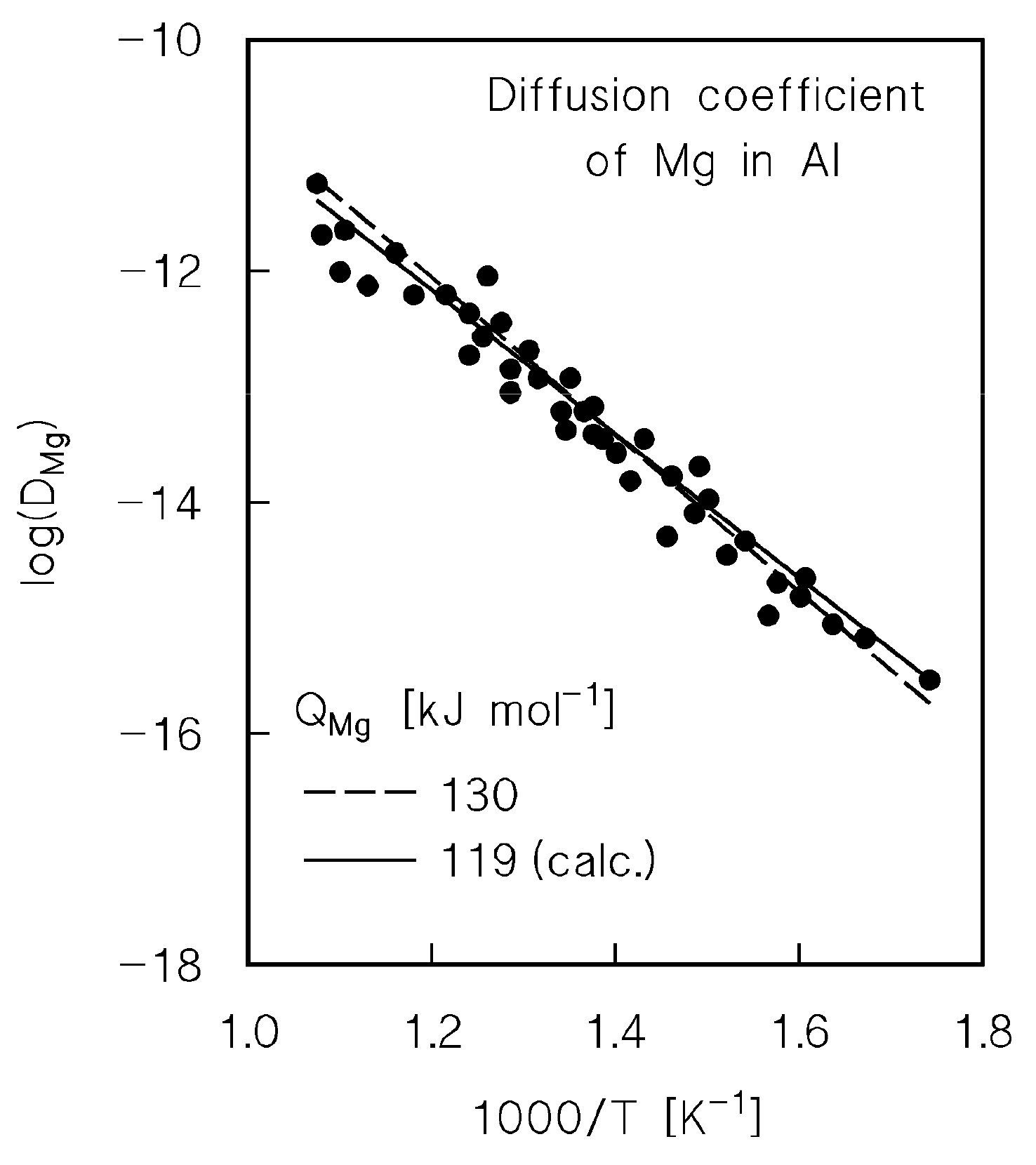
4.1. Diffusion Coefficient

The typical value of the diffusion coefficient parameters for the diffusion of Mg in Al is D0Mg = 1.24 × 10⁻⁴ m2·s−1, Qsd = 130.5 kJ·mol−1 [18]. The accuracy of this estimate was challenged in a recent work [19], which reported a wide collection of literature results on the diffusivity of Mg in Al, which is illustrated in Figure 2. A good fitting is obtained with Qsd = 119 kJ·mol−1 and D0sd = 1.9 × 10⁻⁵ m2·s−1, which actually give a curve very close to the one from [18].

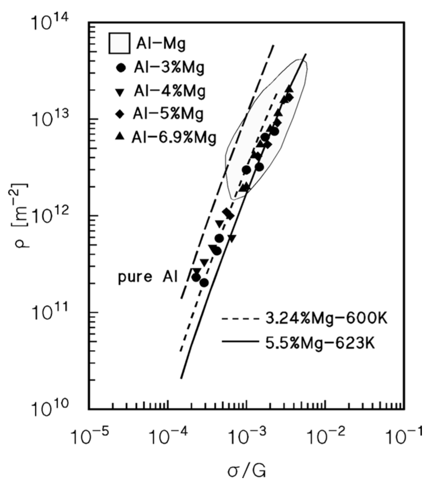
4.2. Drag Stress Calculation and Experimental Datasets on Dislocation Density and Strain Rate

Microstructural data, namely dislocation density variation with applied stress, and previous results on pure Al, will be used to evaluate the accuracy of the model in estimating solid solution stress. Equation (2) can be rewritten as
ρ = ( σ σ i σ s s α m G b ) 2
Figure 3, which collects data from different sources [20,21,22], shows that the experimental value of the dislocation density in Al-Mg is somewhat lower than in pure Al. This behaviour is fully consistent with Equation (15) due to the presence of drag stress. Thus, dislocation density could be properly modelled, as long as the calculated value of drag stress is sufficiently reliable. To proceed in this direction, it is necessary to estimate the dislocation velocity, which can be expressed by combining the well known Orowan equation
ε ˙ = ρ b v d
with Equation (11), giving
v d = C L α m 2 M c g b σ d
The combination of Equations (13) and (17) gives
σ s s = C L M c g σ d c β 2 α m 2 Ω D M g k T I ( z 0 )
or
σ s s = B 1 + B ( σ σ i )
where
B = C L M c g c β 2 α m 2 Ω D M g k T I ( z 0 )
The diffusion coefficient for climb and glide Dcg can be considered to be equivalent to the self-diffusion coefficient of Al. Once the value of the ultimate tensile strength of the different Al-Mg alloys is quantified (with the above-mentioned assumption, Rmax = 1.5RUTS), all of the parameters in Equations (10), (12), and (19) are known. The model curves presented in Figure 3 were thus calculated by Equations (15) and (18). Since the agreement between the curves and the experimental data is excellent, a direct and independent confirmation that the estimation of the drag stress is sufficiently reliable to be used in the model for the steady-state creep rate dependence on applied stress is obtained.
Figure 4 shows the sets of experimental creep data used in this study. The first dataset [4] presents the creep rate at an applied strain of 0.2, i.e., reasonably close to the steady state, at a constant temperature, for different Mg contents (Figure 4a). Although being limited to a single temperature, the dataset represents the classical case study, since the three traditional regimes can be easily recognised. Figure 4a clearly shows low stress Regime I, where creep is thought to be climb-controlled (n = 4–5). Above a transition stress σc, the rate-controlling mechanism should be viscous glide (n = 3). It is only when the applied stress exceeds a limiting value ( σ b a s , frequently identified with the break-away stress, σ b a ) that dislocations are able to break-away from solute atom atmospheres and creep should again become climb-controlled (n = 4–5). The data from [4] are thus well suited to assess the accuracy of the model in describing the effect of different amounts of Mg in solid solution.
The second dataset (Figure 4b), which is related to an Al-2%Mg alloy, was obtained from [16]. This dataset is extremely useful to investigate the accuracy of the model in describing the temperature dependence of the steady-state creep rate.

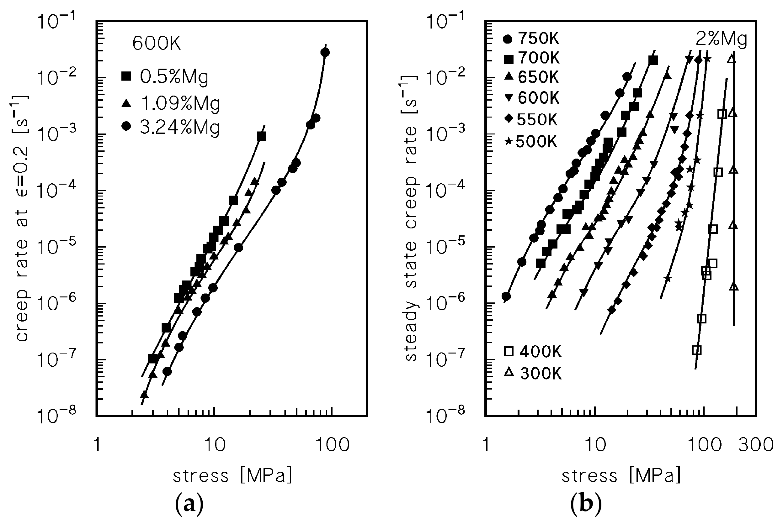
4.3. Viscous-Glide Controlled Creep: Strain Rate Dependence on Stress and Temperature at T ≥ 523 K

The first analysis was focused on the data included in Regimes I and II at high temperatures. In the low-intermediate stress regime, solute atmospheres surround dislocations, exerting a drag stress σ s s . Upon substitution of the drag stress into Equations (10) and (11), the model gives the curves that are presented in Figure 5. It is clearly shown that the model gives an accurate description of the experimental data in the low and intermediate stress regimes, although a significant deviation is observed at high stresses. This behaviour could be rationalised by considering that the model can describe the steady-state creep rate with reasonable accuracy as long as σ < σ b a s . Thus, all of the data points for σ > σ b a s represent the steady-state creep rate in conditions, in which the progressive break-away of dislocations results in a reduction of the strengthening effect of solute atom atmospheres, that is, of the σ s s term.

4.4. Creep Above the Transition for Break-Away of Dislocations from Solute Atom Atmospheres

In the model presented in the previous section, the σ s s term monotonically increases with stress. By contrast, the drag effect should rapidly reduce as dislocations break-away from solute atoms. However, for stresses just above σ b a s , the solid solution stress cannot be reasonably expected to become abruptly non-existent. This behaviour would indeed result in a step in the strain rate plot that is not evident in Figure 4. Rather, it seems more reasonable to suppose that, as stress increases above σ b a s , when the dislocation velocity exceeds a limiting value v b a , a progressively increasing fraction of the Mg atoms is expelled from the solute atmospheres. When the stress is sufficiently high that all the dislocations are free from solute atoms, the material behaves essentially like pure Aluminium—the main difference being that here the dislocation should overcome single Mg atoms, and that the alloy still creeps at a lower rate. In parallel, the homogeneous dislocation distribution typical of class A materials, which is associated to high drag stresses, is progressively replaced by a more heterogeneous distribution with substructure formation [1,2,3].
If such is the situation, the drag stress can no longer monotonically increase, as predicted by Equation (13), but, at a stress correctly identified as break-away stress ( σ b a ), should present a maximum which should be larger than σ b a s .
The behaviour described above was here modelled by supposing that the effect of break-away can be described by an equation in the form
σ s s * = F σ s s
where 0 ≤ F(σ) ≤ 1, σss being the drag stress calculated by Equation (18) A suitable phenomenological form for F is
F = [ 1 + ( σ σ 50 ) h ] 1
where σ 50 is the stress for which the reduced drag stress is a mere half of the computed value of σ s s . For the sake of simplicity, it was here assumed that σ 50 σ b a . This assumption, in turn, implies that to have a maximum in the drag stress for σ = σ b a , due to the peculiar dependence of σ s s on stress, then the exponent h should range from 2, in the high temperature regime, to 3, at 600 K.
The general expression for the break-away stress was given by Friedel [23]
σ b a = m τ b a = m A b a W m 2 c k T b 3
where the maximum interaction energy between solute atoms and an edge dislocation can be expressed as
W m = 1 2 π ( 1 + ν 1 ν ) G | Δ V a |
being ΔVa the difference in volume between solute and solvent atoms (that is, with the formalism used in Equation (8), Wm is directly related to β). In Friedel’s original formulation Aba = 1, giving, for example, a break-away stresses above 400 MPa for 2%Mg at 750 K, a level so high that it is hardly conceivable for this mechanism to play any role in creep. These very high values were considered by some authors [4,24,25] as incompatible with experimental evidence. Their analyses rather suggested that σ b a is one order of magnitude lower, that is, Aba ≅ 0.1 [24,25] or even Aba ≅ 0.065 [26,27]: this reduced value of the break-away stress will be here, denoted as σ b a * . Thus, Equation (23) was here provisionally used with Aba = 0.065, to obtain the values of the reduced drag stress σ s s * . The curves obtained by replacing σ s s with σ s s * into Equation (11) are presented in Figure 6.
The model is now able to describe the material behaviour in the whole range of applied stress, and even the complex change in slope n (= log ε ˙ / log σ ), usually associated to the transition from Regimes I, II and III (Figure 6a), without requiring specific assumptions on the rate-controlling mechanisms.
Examples of the variation of σ * s s as a function of temperature and applied stress are presented in Figure 7. The reduction of the drag stress is the effect of a lower amount of Mg in the atmospheres around dislocations: c* can be identified as the amount of magnesium, still in the solute clouds, which produces a given drag stress σ * s s . The value of c*, as calculated by Equation (21), for a single temperature and alloy is presented in Figure 8, which also plots the corresponding σ * s s and σ s s .

4.5. Hot Working as an Extension of Creep: The Model in the High Strain Rate Plasticity Regime

One of the main tasks of this study is to assess whether the Sandström basic model, modified to account for dislocation break-away, is able to also describe high-strain rate/high-temperature data, i.e., the hot working regime. Figure 9, Figure 10 and Figure 11 illustrate the compression data (stress at 0.3 strain, roughly corresponding to the peak stress of the flow curve) for three different alloys (0.55, 2.2 and 5.5%Mg) [28], and, for comparison purposes, other single creep datasets for 0.48%Mg [4], 2.2%Mg [1,29] and 5.5%Mg [1,30]. The model curves, as calculated by following the same procedure discussed above, i.e., by replacing σ s s with σ * s s , provide an excellent description of the experimental data (the average error is the stress estimation for a given strain rate is 11, 10, and 7% for the alloys containing 0.55, 2.2, and 5.5%Mg, respectively), with the mere exception of the results for 0.5%Mg at 573 K, where the average error reaches 22% (Figure 7). As a matter of fact, at 573 K and at the highest strain rates at 623 K, the reduced drag stress, as calculated by Equation (21), is extremely low, since the stress is far above σ b a * . In this condition, isolated atoms can still retard dislocation motion, an effect that has not been considered in the model, leading to the overestimation of the strain rate in the lower temperature regime. With this notable exception, it can thus be concluded that the basic model presented here can be successfully used to predict, with more than reasonable accuracy, the hot workability response of Al-Mg alloys in the temperature regime between 550 and 850 K, without requiring any best fitting of experimental data. Thus, the predictive capability of the model is fully confirmed, suggesting that it could be profitably used in hot working studies.

5. Conclusions

A unified approach has been presented to describe the high-temperature secondary strain rate dependence on applied stress and temperature for Al-Mg single-phase solid solution alloys in creep and hot working conditions. The physically based constitutive equations proposed contain three important parameters: internal stress, which represents the stress that is required to move a dislocation in the matrix, the strengthening contribution due to solute atom-dislocation interactions (drag stress), and the strain hardening constant CL, which, in combination with free dislocation density, determines the dislocation mean free path. Once the effect of break-away of dislocations from solute atmospheres has been described by a specific relationship, the model proposed does not require any variation in the constitutive equations to describe the whole experimental range of steady-state creep rate, nor data-fitting, which is a notable advancement over other phenomenological equations.

Acknowledgments

The authors greatly thank Rolf Sandström (Materials Science and Engineering, KTH, Brinellvägen 23, S-10044 Stockholm, Sweden) for stimulating the discussion which provided an invaluable contribution to the work here presented.

Author Contributions

S.S. and C.P. analysed the data; S.S. handled the model; C.P. collected literature data; S.S. wrote the paper.

Conflicts of Interest

The authors declare no conflict of interest.

References

  1. Oikawa, H.; Langdon, T.G. The creep characteristics of pure metals and metallic solid solution alloys. In Creep Behaviour of Crystalline Solids; Wilshire, R., Evans, R.W., Eds.; Pineridge Press: Swansea, UK, 1985; pp. 33–82. ISBN 9780906674420. [Google Scholar]
  2. Čadek, J. Creep in Metallic Materials; Elsevier: Amsterdam, The Netherlands, 1988; pp. 160–175. ISBN 9780444989161. [Google Scholar]
  3. Kassner, M.E.; Pérez-Prado, M.T. Fundamentals of Creep in Metals and Alloys; Elsevier: Amsterdam, The Netherlands, 2004; pp. 11–120. ISBN 9780080436371. [Google Scholar]
  4. Oikawa, H.; Honda, K.; Ito, S. Experimental study on the stress range of class I behaviour in the creep of Al-Mg alloys. Mater. Sci. Eng. 1984, 64, 237–245. [Google Scholar] [CrossRef]
  5. Sato, H.; Maruyama, K.; Oikawa, H. Effects of the third element on creep behaviour of Al-Mg and α-Fe-Be sold solution alloys. Mater. Sci. Eng. A 1997, 234–236, 1067–1070. [Google Scholar] [CrossRef]
  6. Horita, Z.; Langdon, T.G. High temperature creep of Al-Mg alloys. In Strength of Metals and Alloys, Proc. ICSMA7; McQueen, H.J., Bailon, J.P., Dickson, J.I., Jonas, J.J., Akben, M.G., Eds.; Pergamon Press: Oxford, UK, 1986; pp. 797–802. ISBN 0080316409. [Google Scholar]
  7. Fernández, R.; González-Doncel, G. A unified description of solid solution creep strengthening in Al-Mg alloys. Mater. Sci. Eng. A 2012, 550, 320–324. [Google Scholar] [CrossRef] [Green Version]
  8. Sandström, R. Influence of phosphorus on the tensile stress strain curves in copper. J. Nucl. Mater. 2016, 470, 290–296. [Google Scholar] [CrossRef]
  9. Sandström, R.; Andersson, H.C.M. Creep in phosphorus alloyed copper during power-law breakdown. J. Nucl. Mater. 2008, 372, 76–88. [Google Scholar] [CrossRef]
  10. Orlová, A.; Čadek, J. Dislocation structure in the high temperature creep of metals and solid solution alloys: A review. Mater. Sci. Eng. 1986, 77, 1–18. [Google Scholar] [CrossRef]
  11. Hirth, J.P.; Lothe, J. Theory of Dislocations; McGraw-Hill: New York, NY, USA, 1978. [Google Scholar]
  12. Kocks, U.F.; Argon, A.S.; Ashby, M.F. Thermodinamics and kinetics of slip. Prog. Mater. Sci. 1979, 15, 1–291. [Google Scholar]
  13. Spigarelli, S.; Sandström, R. Basic creep modelling of Aluminium. Mater. Sci. Eng. A 2018, 711, 343–349. [Google Scholar] [CrossRef]
  14. Korzhavyi, P.A.; Sandström, R. First-principles evaluation of the effect of alloying elements on the lattice parameter of a 23Cr25NiWCuCo austenitic stainless steel to model solid solution hardening contribution to the creep strength. Mater. Sci. Eng. A 2015, 626, 213–219. [Google Scholar] [CrossRef]
  15. Kassner, M.E. Taylor hardening in five-power-law creep of metals and Class-M alloys. Acta Mater. 2004, 52, 1–9. [Google Scholar] [CrossRef]
  16. Mecking, H.; Styczynski, A.; Estrin, Y. Steady state and transient plastic flow of Aluminum and Aluminum alloys. In Strength of Metals and Alloys-ICSMA8; Kettunen, P.O., Lepistö, T.K., Lehtonen, M.E., Eds.; Pergamon Press: Oxford, UK, 1988; pp. 989–994. ISBN 9781483294155. [Google Scholar]
  17. Zhang, L.; Du, Y.; Chen, O.; Steinbach, I.; Huang, B. Atomic mobilities and diffusivities in the fcc, L12 and B2 phases of the Ni-Al system. Int. J. Mater. Res. 2010, 101, 1461–1475. [Google Scholar] [CrossRef]
  18. Rothman, S.J.; Peterson, N.L.; Nowicki, L.J.; Robinson, L.C. Tracer Diffusion of Magnesium in Aluminum Single Crystals. Phys. Status Solidi (b) 1974, 63, K29–K33. [Google Scholar] [CrossRef]
  19. Zhang, W.; Du, Y.; Zhao, D.; Zhang, L.; Xu, H.; Liu, S.; Li, Y.; Liang, S. Assessment of the atomic mobility in FCC Al-Cu-Mg alloys. Calphad 2010, 34, 286–293. [Google Scholar] [CrossRef]
  20. Horiuchi, R.; Otsuka, M. Mechanism of high temperature creep of Aluminum-magnesium solid solution alloys. Trans. Jpn. Inst. Met. 1972, 13, 284–293. [Google Scholar] [CrossRef]
  21. Hayakawa, H.; Nakashima, H.; Yoshinaga, H. Dislocation density and Interaction between dislocations in Al-Mg solution hardened alloys deformed at high temperature. J. Jpn. Inst. Met. 1989, 53, 1113–1122. [Google Scholar] [CrossRef]
  22. Blum, W.; Zhu, Q.; Merkel, R.; McQueen, H.J. Geometric dynamic recrystallization in hot torsion of Al-5 Mg-0.6 Mn (AA5083). Mater. Sci. Eng. A 1996, 205, 23–30. [Google Scholar] [CrossRef]
  23. Friedel, J. Dislocations; Pergamon Press: Oxford, UK, 1964; ISBN 9781483135922. [Google Scholar]
  24. Yavari, P.; Langdon, T.G. An examination of the breakdown in creep by viscous glide in solid solution alloys at high stress level. Acta Metall. 1982, 30, 2181–2196. [Google Scholar] [CrossRef]
  25. Endo, T.; Shimada, T.; Langdon, T.G. The deviation from creep by viscous glide in solid solution alloys at high stresses-characteristics of the dragging stress. Acta Metall. 1984, 32, 1991–1999. [Google Scholar] [CrossRef]
  26. Northwood, D.O.; Moerner, L.; Smith, I.O. The Breakdown in Creep by Viscous Glide in Al-Mg Solid Solution Alloys at High Stress Levels. Phys. Status Solidi (a) 1984, 84, 509–515. [Google Scholar] [CrossRef]
  27. Kim, H.K. Low-temperature creep behavior of ultrafine-grained 5083 Al alloy processed by equal-channel angular pressing. J. Mech. Sci. Technol. 2010, 24, 2075–2081. [Google Scholar] [CrossRef]
  28. Prasad, Y.V.R.K.; Sasidhara, S. Hot Working Guide—A Compendium of Processing Maps; ASM International: Almere, The Netherlands, 1997; pp. 98–100. ISBN 9781627080910. [Google Scholar]
  29. Oikawa, H.; Sugawara, K.; Karashima, S. Creep Behavior of Al-2.2 at% Mg Alloy at 573 K. Trans. Jpn. Inst. Met. 1978, 19, 611–616. [Google Scholar] [CrossRef]
  30. Pahutová, M.; Čadek, J. On Two Types of Creep Behaviour of F.C.C. Solid Solution Alloys. Phys. Status Solidi (a) 1979, 56, 305–313. [Google Scholar]
Figure 1. Steady-state creep rate dependence on applied stress for Al 99.999% [16]; the curves were calculated by Equations (10) and (11) with CL = 86, ω = σss = Uss = 0.
Metals 08 00009 g001
Figure 2. Diffusion coefficient in Al-Mg (set of literature data from [19]). The Figure illustrates the best fitting of the data as well as the curve representing the diffusion coefficient used in the majority of previous studies.
Metals 08 00009 g002
Figure 3. Experimental values of the dislocation density as a function of stress for Al-3%Mg [20,21,22], Al-4%Mg [21], Al-5%Mg [21], and Al-6.9%Mg [20]. The shaded area, which illustrates the scatter band for Al-Mg alloys, was reported in [22]. The Figure also plots the model curve for pure Al [13] and for Al-Mg alloys (3.24% and 5.5%Mg at 600 and 623 K, respectively).
Metals 08 00009 g003
Figure 4. Literature data on the creep of Al-Mg alloys: strain rate at 0.2 strain data from [4] (a) and steady-state creep and steady-state flow stress from constant strain rate experiments from [16] (b).
Metals 08 00009 g004
Figure 5. Description of the experimental data for T > 523 K from [16] by Equations (10) and (11), where the drag stress σss is obtained from Equations (19) and (20).
Metals 08 00009 g005
Figure 6. Description of the experimental data from [4] (a) and [16] (b) by Equations (10) and (11), with σ s s * from Equations (21)–(24). Figure 6a also shows the variation of n = log ε ˙ / log σ for the alloy with 3.24%Mg.
Metals 08 00009 g006
Figure 7. Variation of σ * s s as a function of temperature and applied stress for Al-2%Mg.
Metals 08 00009 g007
Figure 8. Plots for σ * s s , c* and σ s s as a function of modulus compensated stress for 3.24%Mg at 600 K.
Metals 08 00009 g008
Figure 9. Compression data for 0.55%Mg [28] and creep data for 0.48%Mg [4]. The model curves were calculated by Equations (10)–(11), (21)–(24).
Metals 08 00009 g009
Figure 10. Compression data for 2.2%Mg [28] and creep data from [1,29]. The curves were calculated as in Figure 9.
Metals 08 00009 g010
Figure 11. Compression data for 5.5%Mg [28] and creep data from [1,30]. The curves were calculated, as in Figure 9.
Metals 08 00009 g011
Table 1. List of fundamental symbols.
bBurgers vector2.86 × 10−10 m
cconcentration of Mg in solid solution[at %]
CLwork hardening constant86
D0sdpre-exponential factor in equation for self-diffusion8.34 × 10−6 m2·s−1
D0Mgpre-exponential factor in equation for diffusion of Mg in Al1.9 × 10−5 m2·s−1
Gshear modulus at the testing temperature(3.022 × 10¹⁰–1.6 × 10⁷ T) Pa
kBoltzmann constant1.38 × 10−23 J·K−1
Lmean dislocation free path[m]
mTaylor factor3.06
Mcclimb mobility of dislocations[m2·N−1·s−1]
Mcgclimb and glide mobility of dislocations[m2·N−1·s−1]
nstress exponent in power-law equation
Qsdactivation energy for vacancy diffusion (self-diffusion)122 × 103 J·mol−1
QdMgactivation energy for diffusion of Mg in Al119 × 103 J·mol−1
Runiversal gas constant[J·mol−1·K−1]
Rmaxmaximum back stress[Pa]
RUTSultimate tensile strength[Pa]
Tabsolute temperature[K]
vdvelocity of dislocations[m·s−1]
αmaterial constant in Taylor equations0.3
δMgvolume atomic misfit
ε strain
ε ˙ strain rate[s−1]
νPoisson’s ratio0.3
ρfree dislocation density[m−2]
ρafree dislocation density in annealed state[m−2]
σstress (creep or constant strain rate experiments)[Pa]
σbabreak-away stress[Pa]
σiinternal stress[Pa]
σsssolid solution strengthening stress[Pa]
σ*ssreduced solid solution strengthening stress[Pa]
σyyield strength[Pa]
τ l dislocation line tension[N]
ωrecovery constant[Pa]
Ωatomic volume of the host atom (Al)1.66 × 10⁻²⁹ m3

