Influence of Sludge Particles on the Fatigue Behavior of Al-Si-Cu Secondary Aluminium Casting Alloys
by
 , ,
, ,
Lorella Ceschini
1 ,
,
Alessandro Morri
2,
Stefania Toschi
2,*,
Anton Bjurenstedt
3 and
Salem Seifeddine
4 1
Department of Civil, Chemical, Environmental and Materials Engineering, University of Bologna, 40136 Bologna, Italy
2
Department of Industrial Engineering, University of Bologna, 40136 Bologna, Italy
3
Swerea SWECAST, 55322 Jönköping, Sweden
4
Department of Materials and Manufacturing, School of Engineering, Jönköping University, 55111 Jönköping, Sweden
*
Author to whom correspondence should be addressed.
Metals 2018, 8(4), 268; https://doi.org/10.3390/met8040268
Submission received: 22 March 2018
/
Revised: 11 April 2018
/
Accepted: 11 April 2018
/
Published: 14 April 2018
(This article belongs to the Special Issue Light Weight Alloys: Processing, Properties and Their Applications)
Abstract
:Al-Si-Cu alloys are the most widely used materials for high-pressure die casting processes. In such alloys, Fe content is generally high to avoid die soldering issues, but it is considered an impurity since it generates acicular intermetallics (β-Fe) which are detrimental to the mechanical behavior of the alloys. Mn and Cr may act as modifiers, leading to the formation of other Fe-bearing particles which are characterized by less harmful morphologies, and which tend to settle on the bottom of furnaces and crucibles (usually referred to as sludge). This work is aimed at evaluating the influence of sludge intermetallics on the fatigue behavior of A380 Al-Si-Cu alloy. Four alloys were produced by adding different Fe, Mn and Cr contents to A380 alloy; samples were remelted by directional solidification equipment to obtain a fixed secondary dendrite arm spacing (SDAS) value (~10 μm), then subjected to hot isostatic pressing (HIP). Rotating bending fatigue tests showed that, at room temperature, sludge particles play a detrimental role on fatigue behavior of T6 alloys, diminishing fatigue strength. At elevated temperatures (200 °C) and after overaging, the influence of sludge is less relevant, probably due to a softening of the α-Al matrix and a reduction of stress concentration related to Fe-bearing intermetallics.
Keywords:
high pressure die casting; Al-Si-Cu alloys; iron; sludge; intermetallics; fatigue behavior1. Introduction
Aluminum casting alloys are frequently used in several industrial fields, especially in the automotive industry, due to their specific properties in minimizing vehicles’ weight, and therefore, the level of emissions it produces. In this regard, high-pressure die casting (HPDC) is nowadays a common process used to produce complex parts for cars and motorbikes. For this particular process, Al-Si-Cu alloys are the most commonly used materials. Since they are usually secondary alloys (i.e., produced from scrap materials), their chemical composition can vary considerably, especially the Fe, Mn ad Cr content.
Fe is generally considered an impurity for casting alloys, since it induces the formation of brittle and acicular Fe-based particles (β-Al5FeSi) which exert a detrimental role on the mechanical behavior of castings, acting as stress concentrators [1,2,3,4,5]. On the other hand, in HPDC alloys, high levels of Fe are generally added (~1 wt %); this helps in reducing die-soldering issues [6,7,8]. Other alloying elements can act as modifiers of undesirable β phases, fostering the formation of intermetallic compounds characterized by their less harmful morphologies [3,4,6,9,10,11]. Mn, for example, is the most common alloying element to counteract the formation of acicular β phases, while promoting the formation of α particles. A Fe:Mn ratio of less than 2 is usually recommended to avoid the formation of β phases [6,12]. Also, Cr possesses similar qualities if other alloying elements are present [6,13]. Together with Fe and Si, Mn and Cr may induce the generation of primary polygonal intermetallics, called sludge, prior to the formation of dendrites [6]. The generic formula α-Alx(Fe,Mn,Cr)ySiz is commonly accepted and used to describe the stoichiometry of sludge particles. Due to their high specific density, sludge particles generally tend to segregate to the bottom of the melt, settling on the furnace floor [6,13]. Alloy chemical composition, holding temperature and solidification rate may significantly influence amount, size and shape of such intermetallics [6,14,15,16,17].
Some models have been developed to predict the formation of sludge. The following empirical equation, for instance, formulated by Gobrecht [14] and Jorstad [15], relates Fe, Mn and Cr contents to the so-called Sludge Factor (SF):
The SF may thus vary strongly depending on the chemical composition of the alloy; the higher the SF, the higher the amount of sludge present in the microstructure. The effect of sludge particles on the mechanical behavior of Al-Si-Cu alloys is still not well understood. Despite some studies which focused upon the influence of sludge particles on the tensile properties of Al-Si alloys [18,19,20], little work has been carried out about the relationship between sludge and the fatigue behavior of alloys at room and high temperatures.
The aim of this study is to evaluate the effect of Fe, Mn and Cr on the microstructure and mechanical behavior of A380 (Al-Si-Cu) casting alloy, typically used in HPDC process. In particular, the study is focused on the relationship between Fe, Mn and Cr levels, Fe-rich sludge particles and their effect on fatigue strength of alloys both at room and high temperature, on artificially aged and overaged specimens.
2. Materials and Methods
The reference alloy (“A”) is a commercial EN AC-46000, commonly used in HPDC processes. In order to evaluate the effect of SF and sludge particles on the mechanical behavior of such an alloy, four alloys with different Fe, Mn and Cr contents, thus with different SF, were produced (A, B, C and D). Alloys were melted in an electric furnace. The base alloy and master alloys for Fe, Mn and Cr addition were molten at 800 °C; eutectic Si chemical modification by Sr addition (250 ppm) was carried out at 775 °C; the temperature was maintained at this value for 10 min then lowered to 720 °C; the molten alloy was then poured into a permanent die and pre-heated to 250 °C, in order to obtain cylindrical bars. Chemical compositions of the alloys were evaluated by an optical emission spectrometer (OES) SpectroMax. Results of chemical analysis and calculated SF are presented in Table 1.
Die cast bars were then remelted using directional solidification equipment (a detailed description of the equipment can be found in [21]), aiming to produce samples characterized by a fixed secondary dendrite arm spacing (SDAS) value of 10 μm. To this end, the furnace temperature was set at 710 °C, maintained for 30 min, then cooled down by water. The furnace itself was moved upwards at a speed of 3 mm/s, in order to obtain the target SDAS value, thus inducing the required cooling rate. During the process, an Ar gas shield was blown into the machine to protect samples from oxidation. This process yields a lower defect content, since the solidification front pushes oxides towards the top of samples during solidification. Samples were then subjected to hot isostatic pressing (HIP), in order to reduce the internal porosities and their associated detrimental effect on fatigue strength. T6 heat treatment was carried out on HIPped samples as follows: (i) solution treatment at 495 °C for 3 h; (ii) quenching in water at 50 °C; (iii) artificial aging at 210 °C for 2 h.
Microstructural analyses were carried out by Axio Imager optical microscope (OM; Zeiss, Oberkochen, Germany) and Zeiss Evo-50 scanning electron microscope (SEM; Zeiss, Oberkochen, Germany) equipped with an energy dispersive spectroscopy probe (EDS; Oxford INCA 350, Oxfordshire, UK). Optical micrographs were processed by Image-Pro Plus software (Media Cybernetics, Rockville, MD, USA) to collect data on intermetallic particles (IM). Samples for microstructural characterization were prepared according to ASTM E3-01 [22], and etched with a 0.5% HF solution (for SDAS calculation, general microstructure analysis) and 10% H2SO4 (for analyses on sludge particles).
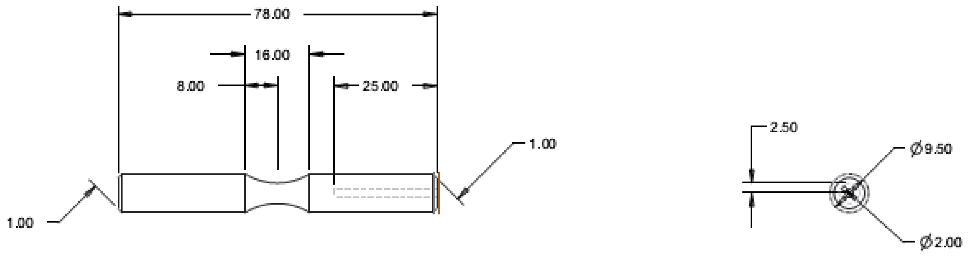
Rotating bending fatigue tests were carried out both at room and high temperatures (200 °C). Room temperature tests were carried out on artificially aged samples (T6 state), while high temperature fatigue tests were carried out on overaged samples (hereafter referred to as OA). Overaging treatment—consisting of soaking samples at 200 °C for 48 h—was carried out after T6 treatment and prior to fatigue testing. Fatigue tests were performed according to ISO 1143 (samples size and geometry are reported in Figure 1); data were analyzed using the staircase method, according to UNI 3964 [23], to calculate fatigue strength (σf50%, the stress yielding to the 50% probability of failure); rotating frequency and run out condition were set to 50 Hz and 2 × cycles respectively.
A stress step of 10 MPa was used. High temperature fatigue tests were carried out by means of a resistance furnace containing the rotating specimens. Samples run for 90 min before applying the load, aiming to reach the steady test temperature (200 °C), as a result of a preliminary thermal control calibration study. The hardness of samples was measured through Brinell tests with a Galileo tester (Officine Galileo, Firenze, Italy) according to ASTME10-08 [24], using a 2.5 mm diameter steel ball and 62.5 kg as a load (HB10 scale). Fracture surfaces of specimens were analyzed by SEM to investigate crack initiation cause and failure mechanisms.
3. Results and Discussion
3.1. Microstructural Analyses
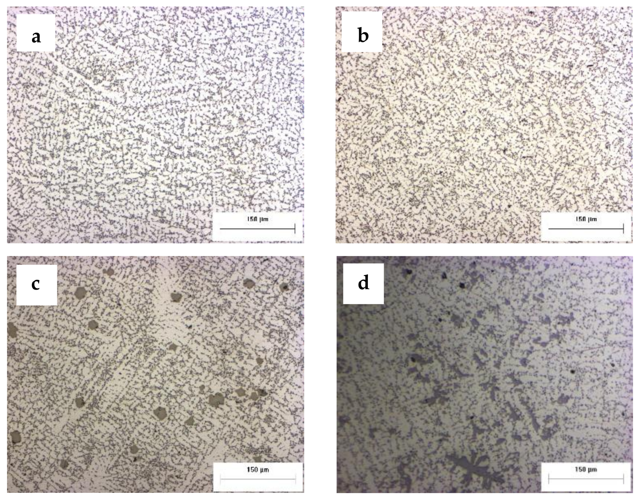
The microstructure of the investigated materials—alloys A, B, C and D—is typical of Al-Si casting alloys consisting of primary α-Al dendrites surrounded by the Al-Si eutectic structure (Figure 2). SDAS evaluation confirmed that the production process allowed us to obtain samples with the desired SDAS value of 10 μm. Average SDAS values calculated for each investigated alloy are reported in Table 2.
On metallographic samples, no internal voids related to gas pores or micro-shrinkage were observed, thanks to the densification action of HIP process.
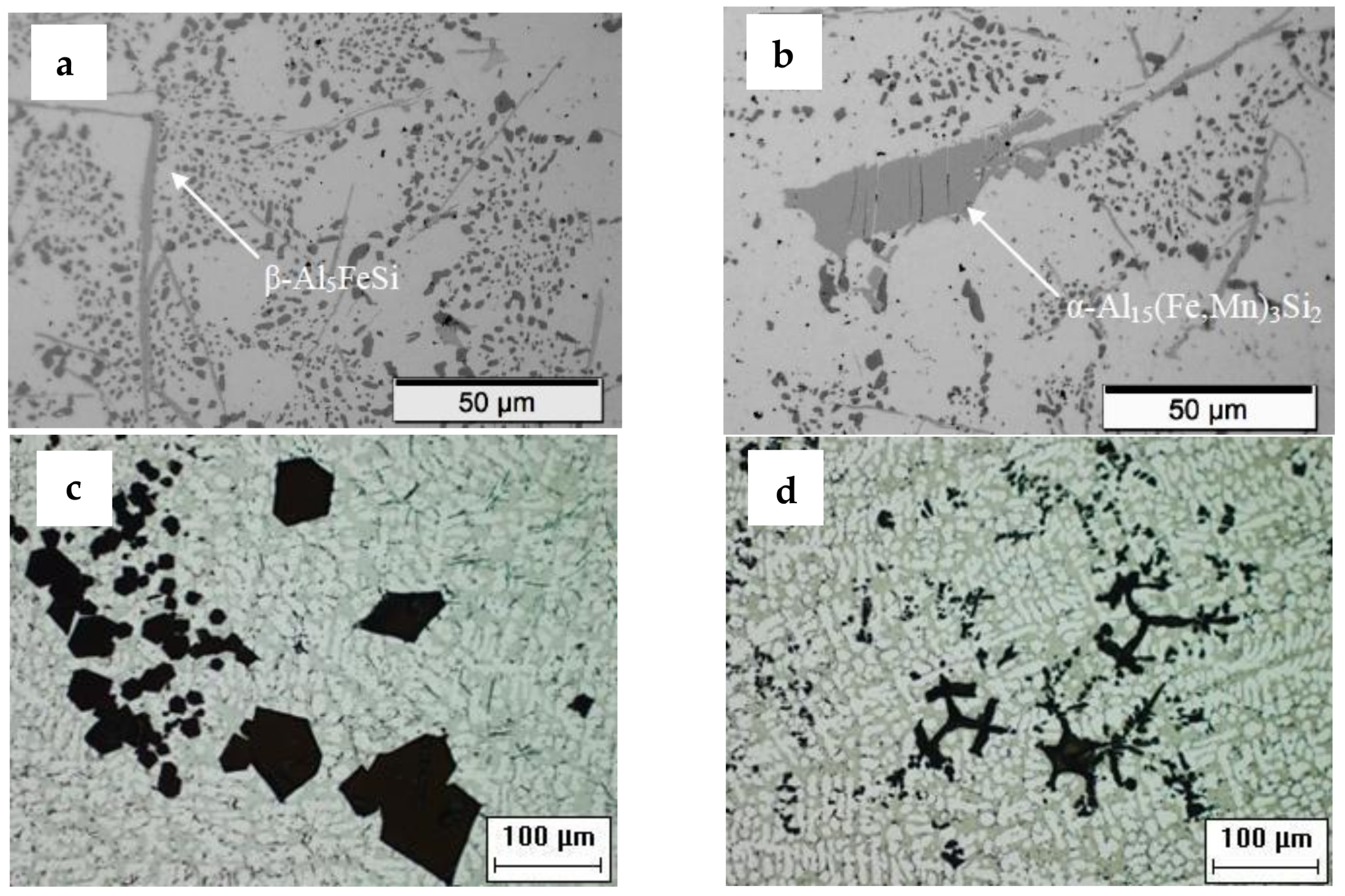
Different intermetallic particles which remained undissolved by solution treatment were observed both in the interdendritic areas, and within α-Al, such as the acicular β-Al5FeSi phases, the α-Al15(Fe, Mn)3Si2 particles, and the Fe-based coarse sludge, to contain Fe, Mn and Cr (Figure 3).
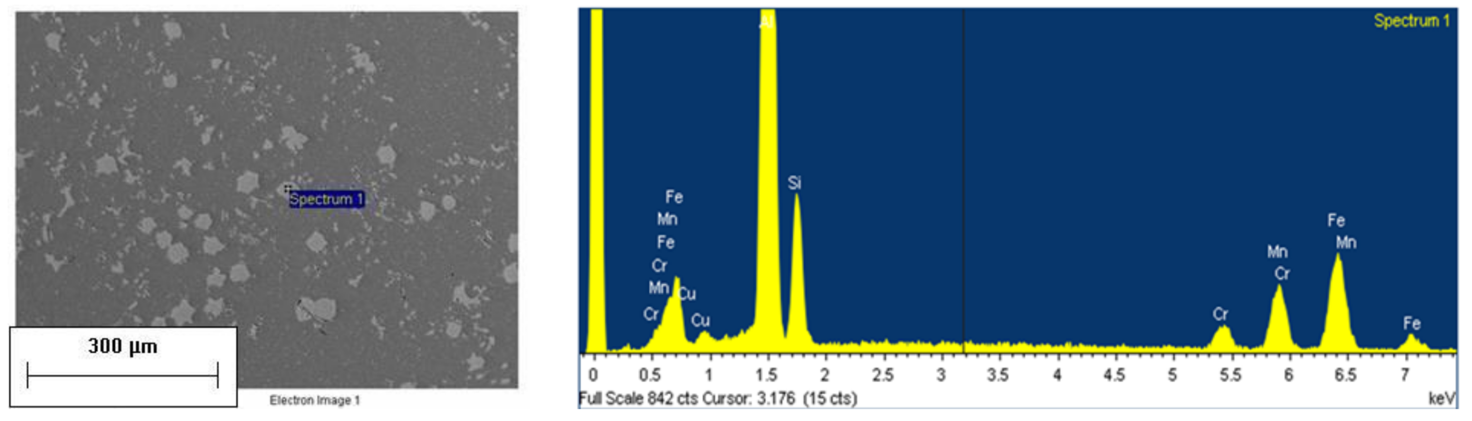
An example of EDS spectrum analysis performed on the sludge particles found in alloy C is reported in Figure 4.
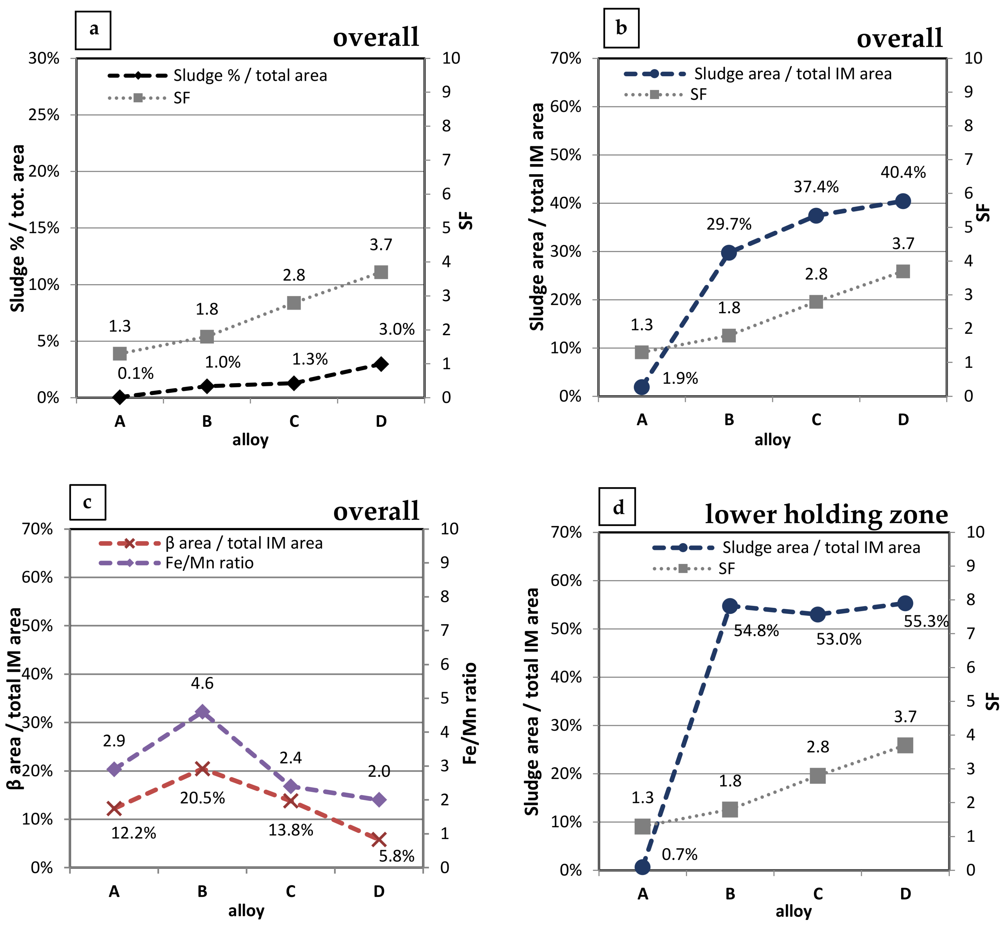
Alloy chemical composition and SF played a relevant role on the type and amount of intermetallic particles formed in the four alloys. Results of the optical images elaboration are reported in Figure 5.
Increasing the SF leads to an overall increase in the area fraction of sludge particles, as represented in Figure 5a. In the base alloy A, corresponding to the lowest SF (1.3), sludge particles cover only 0.1% of the total area, while in alloy D, characterized by the maximum SF (3.7), sludge area is 3.0%. Correspondingly, in alloy A only 1.9% of all the intermetallic particles are represented by sludge; the percentage drastically increases for alloys B, C and D, reaching the maximum fraction of 40.4% in alloy D (Figure 5b).
It is generally known that a Fe:Mn ratio lower than 2 is necessary to prevent the formation of acicular β-Fe [6,12]. As a result, since the nominal Fe/Mn ratio was always ≥2, β-Al5FeSi phases were observed in all the investigated alloys. It is also interesting to note that the IM fraction of β phases in the four alloys is related to the Fe/Mn ratio (Figure 5c): the higher Fe/Mn ratio, the higher is the β-Fe IM fraction. The maximum Fe/Mn ratio (4.6) was alloy B, containing the highest IM fraction of β phases, corresponding to ~20% of all intermetallic particles.
Uneven distribution of sludge particles was observed along the length of samples. Since samples were remelted using the directional solidification technique in a vertical position, a higher amount of sludge phases were found in the lower holding zone of fatigue samples as a result of heavy intermetallic segregation in the bottom of solidified bars. Image analyses showed that in this area, differently from the gauge length, more than 50% of intermetallics in alloys B, C and D were sludge particles (Figure 5d). This confirms the tendency of intermetallic sludge to settle to the bottom of furnaces or crucibles, as reported in literature [6,8,13]. It should be pointed out that such uneven and elevated concentration of sludge particles was circumscribed to the low holding zone, not affecting the gauge length, which is subjected to fatigue loading.
3.2. Mechanical Characterization
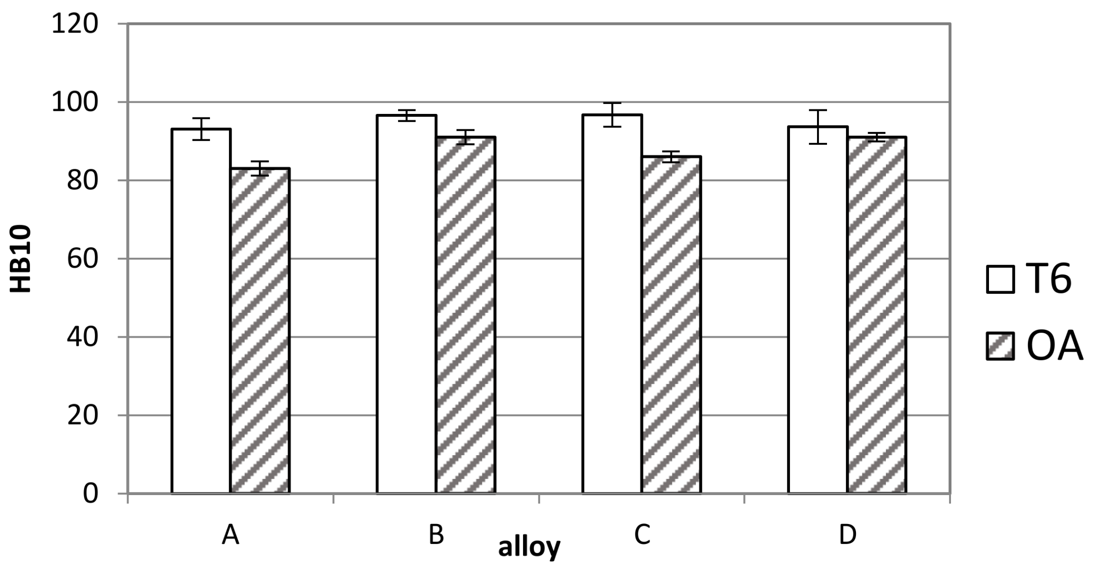
Results of hardness tests on T6 and overaged (OA) alloys are summarized in Figure 6. No significant difference was observed in the T6 condition, since alloys A, B, C and D presented comparable hardness (ranging from 93 to 97 HB10). A certain decrease of hardness was registered in all the alloys after overaging: long-term high temperature exposure induced coarsening of strengthening precipitates and consequent α-Al softening, thus resulting in a loss of strength.
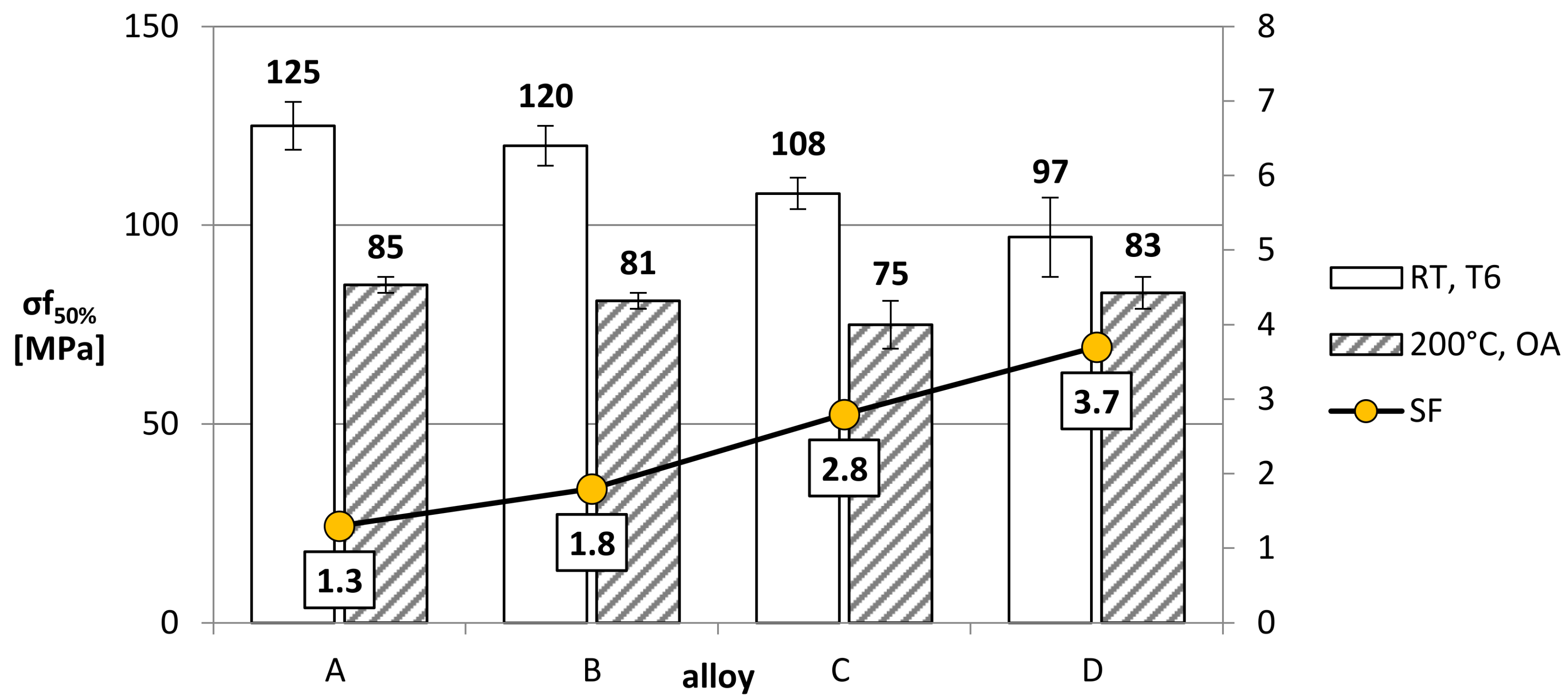
Results of rotating bending fatigue tests are summarized in Figure 7. It can be seen that SF plays a detrimental role on fatigue behavior. At room temperature, σf50% of T6 alloys gradually decreased with an increase in the SF; a loss of about 22% in fatigue strength was registered from alloy A to alloy D. It is thought that this behavior is related to the presence of sludge intermetallic particles. As known, coarse Fe-bearing intermetallic particles could hinder dislocation movement, leading to a piling-up at the α-Al matrix-intermetallics interface, and consequent stress concentration.
Despite the fact that the applied cyclic load is lower than the yielding level, local yielding would occur in any case due to microscale effects related to inhomogeneous deformation of microstructural constituents [26,27]. As a result of such interaction, local internal stresses and damage rate increase, leading to decohesion between intermetallics and matrix, particle cracking, and related crack nucleation. Since under low applied stresses the fatigue behaviour is mainly governed by crack nucleation stage, the presence of coarse intermetallic compounds such as the α-Alx(Fe,Mn,Cr)ySiz sludge particles should significantly reduce the fatigue strength of the alloys, as reported in [26,27,28]. A marked decrease in fatigue strength was registered at high temperature after overaging in comparison to room temperature and in the T6 state. This is ascribed both to the coarsening of strengthening precipitates induced by long-term high temperature exposure leading to an overall decrease of mechanical strength, and to the softening of α-Al matrix, known to cause reduction of UTS and, correspondingly, fatigue strength [29,30,31]. Nevertheless, it should be pointed out that at high temperature and after overaging, the effect of SF on fatigue behavior was almost negligible, since the σf50% of alloys A, B, C and D are basically comparable. It is thought that, at high testing temperature, a softening of the matrix may induce a reduction of stress concentrations associated with intermetallic compounds, thus reducing the gap between the fatigue strength of alloys with different SF. Similar findings were reported by the authors in [29].
3.3. Fractographic Analyses
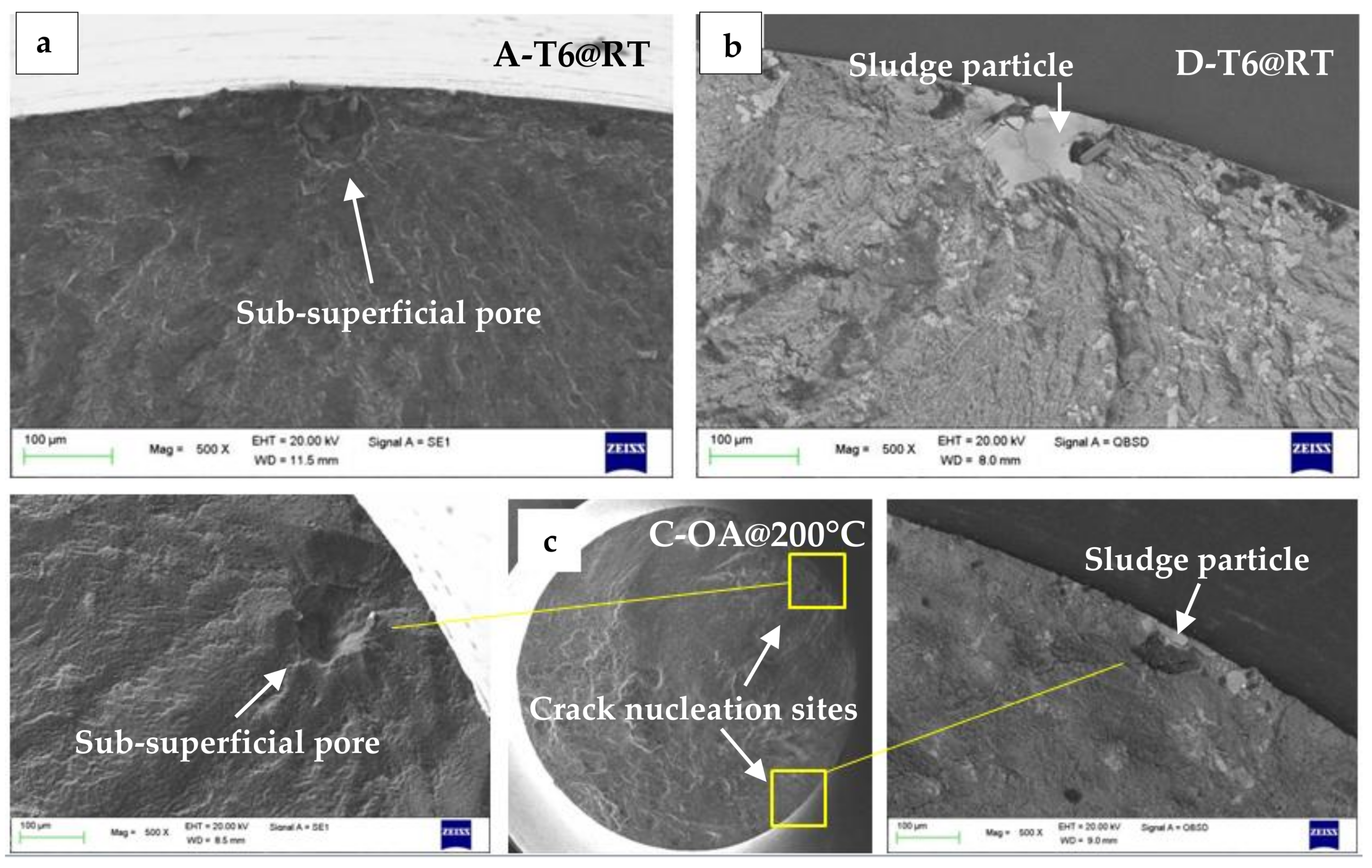
An analysis of fracture surfaces revealed that cracks nucleated always near the sample surface, where the highest stresses induced by rotating fatigue loading were registered. In alloys A and B, both at room and high temperature, cracks were nucleated mainly in the correspondence of casting defects. Superficial and sub-superficial voids are, in fact, not easily closed by the HIP process.
As a result, in alloys A and B, fatigue cracks were initiated by superficial or sub-superficial pores, oxides and microshrinkages. An example of a sub-superficial pore nucleating fatigue crack is reported in Figure 8a. In alloys C and D, characterized by higher amount of sludge particles in comparison to A and B, a relationship between sludge and crack nucleation was observed. At room temperature in the T6 condition, cracks were in fact generated by superficial sludge particles (Figure 8b), confirming the link between Fe-bearing intermetallics and crack nucleation.
At high temperatures, on the other hand, for the alloys C and D, different crack nucleation causes were identified, such as sludge particles, casting defects, as well as multiple initiators (e.g., sludge and pore in different locations of the sample surface, as shown in Figure 8c). This occurrence reflects the higher sensitivity of T6 alloys to stress concentration induced by sludge particles in comparison to the overaged alloys tested at high temperature, as inferred in Section 3.2. From the analysis of nucleation causes, it seems that a defect critical size exists, as widely discussed by Wang et al. [26,27]: in all the investigated alloys, superficial/sub-superficial pores generating fatigue cracks were characterized by a minimum size of ~30 μm, while sludge particles causing crack nucleation on the sample fracture were generally characterized by a minimum size of 40–50 μm. Although more accurate analyses should be carried out on this respect, this fact could indicate that, at SDAS and loading conditions of the present investigation, pores are more detrimental than Fe-based sludges to fatigue life.
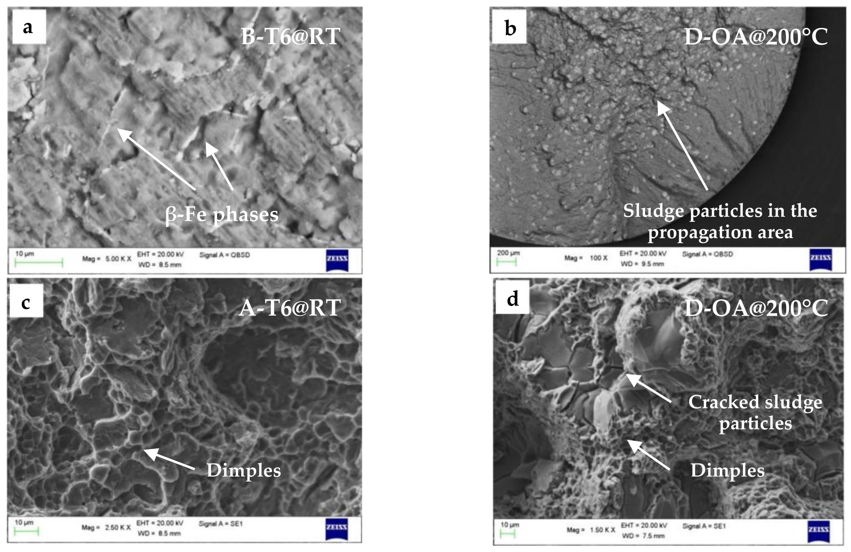
In accordance with the results of microstructural analyses, different kind of intermetallics were found on propagation areas of the different alloys. Alloys A and B were characterized by β-Fe needles (Figure 9a), while alloys C and D presented a high amount of coarse sludge particles (Figure 9b).
The final failure region of T6 and overaged alloys was characterized, both at room and high temperature, by a typical ductile morphology. In alloys A and B, only dimples and small intermetallics were observed (Figure 9c), whereas in alloys C and D, a large amount of cracked and decohesed sludge particles were found (Figure 9d).
4. Conclusions
- In the investigated Al-Si-Cu alloys, sludge factor (SF) is a good indicator of the tendency to form coarse, Fe-based sludge particles containing Fe, Mn and Cr; this was reflected in the different sludge area fractions in the tested alloys.
- A segregated microstructure was observed in samples of alloys B, C and D, characterized by SF of 1.8, 2.8 and 3.7 respectively. The heavy sludge particles tend to settle towards the bottom of the samples. The highest IM fraction of β-Al5FeSi phases was found in alloy B, characterized by the highest Fe:Mn ratio.
- Fatigue behavior is negatively affected by SF; at room temperature and in the T6 condition, a decrease of 22% in fatigue strength was registered from alloy A (base alloy) to alloy D, characterized by the highest SF and containing the maximum area fraction of sludge particles.
- At high temperature, overaged alloys presented an overall decrease in fatigue strength in comparison to the T6 condition at room temperature, because of a coarsening of strengthening precipitates and α-Al softening. Nevertheless, a less marked effect of SF was registered on fatigue strength.
- While at room temperature the cracks in alloys C and D nucleated mainly in correspondence with sludge particles, at 200 °C different nucleation causes were observed, namely: sludge, casting defects and multiple crack initiators. It is thought that, at high temperature, softening of the matrix causes a reduction of stress concentration which is induced by intermetallic sludge particles, thereby reducing their detrimental effect on fatigue life.
Acknowledgments
The authors gratefully acknowledge Marcello Gobbi for his experimental Master Thesis work.
Author Contributions
University of Jönköping produced samples for mechanical characterization and carried out part of the work on microstructural analyses; fatigue testing and fractographic analyses were carried out at University of Bologna; all the authors contributed to data evaluation, discussion and paper writing.
Conflicts of Interest
The authors declare no conflict of interest.
References
- Crepeau, P. Effect of iron in Al-Si casting alloys: A critical review. AFS Trans. 1995, 103, 361–366. [Google Scholar]
- Couture, A. Iron in aluminum casting alloys—A literature survey. Int. J. Cast Met. Res. 1981, 6, 9–17. [Google Scholar]
- Dinnis, C.; Taylor, J.; Dahle, A. As-cast morphology of iron-intermetallics in Al–Si foundry alloys. Scr. Mater. 2005, 53, 955–958. [Google Scholar] [CrossRef]
- Ma, Z.; Samuel, A.M.; Samuel, F.H.; Doty, H.W.; Valtierra, S. A study of tensile properties in Al–Si–Cu and Al-Si-Mg alloys: Effect of β-iron intermetallics and porosity. Mater. Sci. Eng. A 2008, 490, 36–51. [Google Scholar] [CrossRef]
- Seifeddine, S.; Svensson, I.L. Prediction of mechanical properties of cast aluminium components at various iron contents. Mater. Des. 2010, 31, 6–12. [Google Scholar] [CrossRef]
- Shabestari, S.G. The effect of iron and manganese on the formation of intermetallic compounds in aluminum-silicon alloys. Mater. Sci. Eng. A 2004, 383, 289–298. [Google Scholar] [CrossRef]
- Shankar, S.; Apelian, D. Die soldering: Mechanism of the interface reaction between molten aluminum alloy and tool steel. Metall. Mater. Trans. B 2002, 33, 465–476. [Google Scholar] [CrossRef]
- Makhlouf, M.; Apelian, D. Casting Characteristics of Aluminum Die Casting Alloys; Report Performed under DOE Contract Number DEFC07-99ID13716; Worcester Polytechnic Institute (US): Worcester, MA, USA, 2002. [Google Scholar]
- Seifeddine, S.; Johansson, S.; Svensson, I.L. The influence of cooling rate and manganese content on the β-Al5FeSi phase formation and mechanical properties of Al-Si-based alloys. Mater. Sci. Eng. A 2008, 490, 385–390. [Google Scholar] [CrossRef]
- Ceschini, L.; Boromei, I.; Morri, A.; Seifeddine, S.; Svensson, I.L. Microstructure, tensile and fatigue properties of the Al-10%Si-2%Cu alloy with different Fe and Mn content cast under controlled conditions. J. Mater. Process. Technol. 2009, 209, 5669–5679. [Google Scholar] [CrossRef]
- Hwang, J.Y.; Doty, H.; Kaufman, M.J. The effects of Mn additions on the microstructure and mechanical properties of Al-Si-Cu casting alloys. Mater. Sci. Eng. A 2008, 488, 496–504. [Google Scholar] [CrossRef]
- Taylor, J.A. The Effect of Iron in Al-Si Casting Alloys. In Proceedings of the 35th Australian Foundry Institute National Conference on Casting Concepts, Adelaide, South Australia, 31 October–3 November 2004. [Google Scholar]
- Shabestari, S.G.; Gruzleski, J.E. Gravity segregation of complex intermetallic compounds in liquid aluminum-silicon alloys. Metall. Mater. Trans. A 1995, 26, 999–1006. [Google Scholar] [CrossRef]
- Gobrecht, J. Settling-out of Fe, Mn and Cr in Al-Si casting alloys. Giesserei 1975, 62, 263–266. [Google Scholar]
- Jorstad, J. Understanding sludge. Die Cast. Eng. 1986, 30, 30–36. [Google Scholar]
- Wang, L.; Makhlouf, M.; Apelian, D. Aluminium die casting alloys: Alloy composition, microstructure, and properties-performance relationships. Int. Mater. Rev. 1995, 40, 221–238. [Google Scholar] [CrossRef]
- Ferrero, S.; Timelli, G.; Fabrizi, A. Evolution of sludge particles in secondary die-cast aluminium alloys as function of Fe, Mn and Cr contents. Mater. Chem. Phys. 2015, 153, 168–179. [Google Scholar] [CrossRef]
- Bjurenstedt, A.; Seifeddine, S.; Jarfors, A.E.W. The effects of Fe-particles on the tensile properties of Al-Si-Cu alloys. Metals 2016, 6, 314. [Google Scholar] [CrossRef]
- Ji, S.; Yang, W.; Gao, F.; Watson, D.; Fan, Z. Effect of iron on the microstructure and mechanical property of Al-Mg-Si-Mn and Al-Mg-Si die cast alloys. Mater. Sci. Eng. A 2012, 564, 130–139. [Google Scholar] [CrossRef]
- Timelli, G.; Bonollo, F. The influence of Cr content on the microstructure and mechanical properties of AlSi9Cu3 (Fe) die-casting alloys. Mater. Sci. Eng. A 2010, 528, 273–282. [Google Scholar] [CrossRef]
- Seifeddine, S. Characteristics of Cast Aluminium-Silicon Alloys: Microstructures and Mechanical Properties. Linköping studies in Science and Technology: Dissertations; Ph.D. Thesis, Linköping University, Linköping, Sweden, 2006. [Google Scholar]
- ASTM E3-01. Standard Practice for Preparation of Metallographic Specimens; ASTM International: West Conshohocken, PA, USA, 2007. [Google Scholar]
- UNI Standard. Mechanical Testing of Metallic Materials Fatigue Testing at Room Temperature; UNI 3964-85; Ente Nazionale Italiano di Unificazione: Milan, Italy, 1985. [Google Scholar]
- ASTM E10-08. Standard Test Method for Brinell Hardness of Metallic Materials; ASTM International: West Conshohocken, PA, USA, 2007. [Google Scholar]
- Gobbi, M. Influence of Sludge Particles on the Mechanical Properties of Al-Si-Cu-Mg Secondary Casting Aluminium Alloy; University of Bologna: Bologna, Italy, 2014. [Google Scholar]
- Wang, Q.G.; Apelian, D.; Lados, D.A. Fatigue behavior of A356-T6 aluminum cast alloys. Part I. Effect of casting defects. J. Light Met. 2001, 1, 73–84. [Google Scholar] [CrossRef]
- Wang, Q.G.; Apelian, D.; Lados, D.A. Fatigue behavior of A356/357 aluminum cast alloys. Part II—Effect of microstructural constituents. J. Light Met. 2001, 1, 85–97. [Google Scholar] [CrossRef]
- Ceschini, L.; Boromei, I.; Morri, A.; Seifeddine, S.; Svensson, I.L. Effect of Fe content and microstructural features on the tensile and fatigue properties of the Al-Si10-Cu2 alloy. Mater. Des. 2012, 36, 522–528. [Google Scholar] [CrossRef]
- Ceschini, L.; Morri, A.; Toschi, S.; Seifeddine, S. Room and high temperature fatigue behaviour of the A354 and C355 (Al-Si-Cu-Mg) alloys: Role of microstructure and heat treatment. Mater. Sci. Eng. A 2016, 653, 129–138. [Google Scholar] [CrossRef]
- Ceschini, L.; Morri, A.; Morri, A.; Toschi, S.; Johansson, S.; Seifeddine, S. Effect of microstructure and overaging on the tensile behavior at room and elevated temperature of C355-T6 cast aluminum alloy. Mater. Des. 2015, 83, 626–634. [Google Scholar] [CrossRef]
- Ceschini, L.; Morri, A.; Toschi, S.; Johansson, S.; Seifeddine, S. Microstructural and mechanical properties characterization of heat treated and overaged cast A354 alloy with various SDAS at room and elevated temperature. Mater. Sci. Eng. A 2015, 648, 340–349. [Google Scholar] [CrossRef]
Figure 1.
Geometry of fatigue samples; dimensions are expressed in mm.

Figure 2.
Low-magnification optical images showing the microstructure of alloys (a) A; (b) B; (c) C and (d) D, consisting in α-Al dendrites, Al-Si eutectic and intermetallic particles.
Figure 2.
Low-magnification optical images showing the microstructure of alloys (a) A; (b) B; (c) C and (d) D, consisting in α-Al dendrites, Al-Si eutectic and intermetallic particles.

Figure 3.
Optical images of intermetallic particles: (a) β-Fe phases; (b) α-Fe phase; (c) blocky-like and (d) star-like sludges; (a, b from [25]).
Figure 3.
Optical images of intermetallic particles: (a) β-Fe phases; (b) α-Fe phase; (c) blocky-like and (d) star-like sludges; (a, b from [25]).

Figure 4.
EDS spectrum of a sludge particle observed in C-T6 alloy [25].
Figure 4.
EDS spectrum of a sludge particle observed in C-T6 alloy [25].

Figure 5.
Results of optical images analyses, showing (a) the relation between SF and percentage of area covered by sludge particles; (b) correspondence between SF and sludge IM fraction calculated on the overall length of the sample; (c) variation of β-Fe IM fraction with Fe/Mn ratio and (d) the relation between sludge IM fraction and SF in the lower holding zone of fatigue specimens.

Figure 6.
Brinell hardness (HB10 scale) measured on T6 and overaged (OA) alloys.

Figure 7.
Fatigue strength (σf50%) and SF of the investigated alloys, tested at room temperature in the T6 condition, and at 200 °C after T6 and overaging (48 h at 200 °C).
Figure 7.
Fatigue strength (σf50%) and SF of the investigated alloys, tested at room temperature in the T6 condition, and at 200 °C after T6 and overaging (48 h at 200 °C).

Figure 8.
SEM images of fracture surfaces: (a) sub-superficial pore inducing crack nucleation in A-T6 alloy; (b) crack nucleated on sample surface by a sludge particle in D-T6 alloy; (c) multiple crack nucleation in C-OA alloy tested at 200 °C, caused by sub-superficial pore and superficial particle.

Figure 9.
SEM images of fracture surfaces, showing (a) β-Fe phases in the propagation area of a B-T6 sample; (b) a dense population of sludge particles in the propagation area of D-OA alloy; (c) ductile morphology of final failure region in A-T6 alloy and (d) final failure area of D-OA alloy tested at 200 °C characterized by cracked sludge particles and dimples.


Table 1.
Alloys’ chemical compositions measured by OES (wt %, except for Sr* in ppm) and corresponding SF.
Table 1.
Alloys’ chemical compositions measured by OES (wt %, except for Sr* in ppm) and corresponding SF.
| Alloy | Si | Cu | Mg | Fe | Mn | Cr | Zn | Ni | Sr* | Al | SF |
|---|---|---|---|---|---|---|---|---|---|---|---|
| A | 9.30 | 2.79 | 0.05 | 0.74 | 0.25 | 0.03 | 0.96 | 0.04 | 220 | Bal. | 1.3 |
| B | 9.40 | 2.77 | 0.05 | 1.17 | 0.25 | 0.03 | 0.91 | 0.04 | 270 | Bal. | 1.8 |
| C | 9.23 | 2.65 | 0.04 | 1.29 | 0.53 | 0.15 | 0.86 | 0.04 | 250 | Bal. | 2.8 |
| D | 9.30 | 2.64 | 0.04 | 1.59 | 0.80 | 0.18 | 0.80 | 0.04 | 260 | Bal. | 3.7 |
Table 2.
Average SDAS value calculated on T6 alloys.
| Alloy | Average SDAS (μm) |
|---|---|
| A | 9.7 ± 2.0 |
| B | 9.8 ± 1.7 |
| C | 9.7 ± 1.3 |
| D | 9.6 ± 1.6 |
© 2018 by the authors. Licensee MDPI, Basel, Switzerland. This article is an open access article distributed under the terms and conditions of the Creative Commons Attribution (CC BY) license (http://creativecommons.org/licenses/by/4.0/).
Share and Cite
MDPI and ACS Style
Ceschini, L.; Morri, A.; Toschi, S.; Bjurenstedt, A.; Seifeddine, S. Influence of Sludge Particles on the Fatigue Behavior of Al-Si-Cu Secondary Aluminium Casting Alloys. Metals 2018, 8, 268. https://doi.org/10.3390/met8040268
AMA Style
Ceschini L, Morri A, Toschi S, Bjurenstedt A, Seifeddine S. Influence of Sludge Particles on the Fatigue Behavior of Al-Si-Cu Secondary Aluminium Casting Alloys. Metals. 2018; 8(4):268. https://doi.org/10.3390/met8040268
Chicago/Turabian StyleCeschini, Lorella, Alessandro Morri, Stefania Toschi, Anton Bjurenstedt, and Salem Seifeddine. 2018. "Influence of Sludge Particles on the Fatigue Behavior of Al-Si-Cu Secondary Aluminium Casting Alloys" Metals 8, no. 4: 268. https://doi.org/10.3390/met8040268
Note that from the first issue of 2016, this journal uses article numbers instead of page numbers. See further details here.