Effects of Mold Temperature on the Microstructure and Tensile Properties of Ti@(Al-Si-Ti)p/A356 Composite Prepared via Powder Thixoforming


State Key Laboratory of Advanced Processing and Recycling of Nonferrous Metals, Lanzhou University of Technology, Lanzhou 730050, China
*
Author to whom correspondence should be addressed.
Metals 2018, 8(10), 829; https://doi.org/10.3390/met8100829
Submission received: 7 October 2018
/
Revised: 12 October 2018
/
Accepted: 13 October 2018
/
Published: 15 October 2018
Abstract
:A novel A356 Al-based composite reinforced with Ti@(Al-Si-Ti) core-shell-structured particles (Ti@(Al-Si-Ti)p) was prepared utilizing powder thixoforming method. The effects of mold temperature on the microstructures and tensile properties of the composites, as well as the toughening mechanisms, were investigated. The results indicated that the primary α-Al particles gradually coarsened and evolved into large-sized interconnected particles with the rise of mold temperature. Simultaneously, the core-shell structured reinforcements tended to agglomerate and the eutectic Si phases gradually coarsened and became spheroidal. The tensile properties of the synthesized composites firstly increased as the mold temperature rose from 150 °C to 200 °C due mainly to the improvement of the microstructure compactness and the spheroidization of the eutectic Si phases, and then decreased resulting from the coarsening of both the primary particles and eutectic Si phases, the agglomeration of the reinforcing particles and the deteriorated microstructure compactness. The composite thixoformed at 200 °C had an excellent elongation of 8.3% besides high tensile strengths. The excellent ductility can be attributed to decreased crack size in the shell and delayed crack propagation by plastic deformation, and multiplication of secondary cracks in the Ti core that originated from the core-shell structure of the reinforcements.
1. Introduction
Particle reinforced aluminum metal matrix composites (PRAMCs) is one of the most attractive materials, and have been widely applied in electricity, aerospace and automobile industries, due to their high specific strength and wear resistance, and low coefficient of thermal expansion [1]. Generally, there are two methods to incorporate reinforcing particles into aluminum matrix, one is direct addition and the other is in-situ formation. For the former, the particles are always ceramic particulates, such as Al2O3 [2] and SiC [3], and for the latter, the reinforcements are usually some Al containing compounds, such as Al3Ti [4], Al3Ni [5] or Al3Fe [6], and so on. Comparatively, the PRAMCs prepared by the latter method usually have higher mechanical properties, due to uniform distribution of the in situ formed reinforcements and high interface bonding strength [7]. But no matter what the method is, the improvements of strength and hardness are always at the cost of ductility deterioration. That is, the inverse relationship between strength and ductility is still existed. Considerable efforts have been devoted to address this problem, and one of the most effective ways is to use graphene nanoplatelets as reinforcements. The resulting composites not only have high strength, but also have excellent ductility that is similar to that of the corresponding matrix alloy [8,9,10]. But it is quite difficult to uniformly disperse graphene nanoplatelets into the matrix although some complicated techniques are utilized, which seriously limits the development of this kind composite [9,10]. Another simple way is to substitute the commonly-used monolithic reinforcements by core-shell structured ones, in which a metallic core is surrounded by an intermetallic shell. For this case, the firstly formed cracks are constrained within the thin intermetallic shells, and thus, their sizes are obviously decreased compared with the ones generated in the monolithic particles with the same size to the core-shell structured particles. In addition, the subsequent propagation of the cracks is also delayed by the soft metallic cores and Al matrix through blunting the crack tips. The ductility of the resulting composite is thereby expected to be improved. Wang and Xue et al. prepared a kind of core-shell structured Fe-AlxFey particles (a Fe core is surround by a AlxFey shell for each reinforcing particle) reinforced pure Al matrix composite by powder metallurgy [11,12]. The Fe-AlxFey particle generated through the reaction between Fe and Al powders during sintering. Subsequently, Guo et al. substituted Fe powders by Ti powders to fabricate Ti-Al3Ti core-shell structured particle reinforced Al matrix [13]. All of the results show that both the resulting composites have high compressive strength and ductility. But unfortunately, the tensile mechanical properties, especially the tensile elongation, are still quite poor due to low microstructure compactness and irregular morphology of the reinforcements. The authors proposed a new technology, named powder thixoforming, based on the powder metallurgy and thixoforming [14,15,16]. For this technology, a Ti-Al green compact is first obtained using the blending and pressing steps of powder metallurgy, then it is heated at a semisolid temperature of the Al matrix alloy for a proper duration and is finally thixoformed. It can be expected that the desired Ti-Al3Ti core-shell structured reinforcing particles will be generated during the heating besides achieving a semisolid ingot available for thixoforming. As known, the most important advantage of thixoforming is to decrease, even eliminate pores, and get a component with compact microstructure [17]. In addition, the core-shell structured particles with a spheroidal morphology can also be obtained if spheroidal Ti powders are used [14]. Therefore, the proposed powder thixoforming should be a promising way to overcome the problem about the reverse relationship between strength and ductility of PRAMCs, and thus, to fabricate PRAMCs with both high strength and excellent ductility.
In the authors’ previous work, the microstructural evolutions of Ti-A356 and Ti-2024 compacts during partial remelting were investigated [14,15]. The results indicated that spheroidal core-shell structured reinforcing particles could be achieved for both systems besides the semisolid ingots available for thixoforming. However, the formation rates and phase constituents of the intermetallic shells were different for these two systems. In addition, the shells would fracture and peel off from the Ti cores when they grew to a given thickness, because of volume expansion resulted from the reaction between Ti powders and Al melts, and the thickness values corresponding to fracture were also different for the two systems. That is, the alloying elements have large effect on the formation of core-shell structured particles. Therefore, the authors investigated the effects of alloying elements, such as Si, Cu, Mg and Zn on the formation of reinforcing particles [16]. The results revealed that only Si element participated in the reaction and accelerated the formation of thick and compact intermetallic shells. So it is expected that the ideal core-shell structured reinforcing particles can be easily achieved in Si-containing Al alloys (i.e., A356 alloy) and the resulting composites should have high tensile properties. However, the existing investigations, as discussed above, have only studied the fabrication of semisolid ingots prior to thixoforming and have not involved the mechanical properties of the thixoformed composites.
In addition, for the toughening mechanisms of the core-shell structured particle reinforced metal matrix composites, as described above, the existing investigations only proposed that the cracks first formed in the reinforcements are constrained with the thin shells, and thus their sizes are smaller than those formed in the same-sized monolithic particles based on metallographic observation, and the relatively soft metallic (Fe, Ti) cores can delay crack propagation by blunting cracks tips [11,12,13]. The detailed mechanisms related to the reinforcement behaviors, i.e., the fracture process of the reinforcement during tensile testing, are still unclear.
Therefore, in this work, the composite from the Ti-A356 system was fabricated by powder thixoforming, and the effects of one main processing parameter, mold temperature, on the microstructures and the tensile properties of the resulting composites were investigated. More importantly, the toughening mechanisms were discussed through careful observations of the fracture surfaces and in situ tensile testing.
2. Materials and Methods
A356 alloy powder (average size of 16.23 µm), Ti powder (99.99% purity, average size of 18.65 µm) and Al powder (99.98% purity, average size of 11.82 µm) were employed in this work as the raw materials. The A356 alloy powder was mixed by Al-15Si-Mg alloy powder and pure Al powder and its composition was accorded to that of A356 alloy.
Firstly, certain amounts of A356 powder (40 g), pure Ti powder (2.05 g) and pure Al powder (3.48 g) were blended in a ND7-21 planetary ball-milling machine (Nanjing Levinstep Technology Co., Ltd., Nanjing, China) for 40 min with a rotation speed of 100 rpm. The ball to powder weight ratio was 5:1. The amount of Ti powder added was determined by the reaction to form a volume fraction of 10% Al3Ti particles and the added extra pure Al powder was to compensate the Al element consumed by the reaction with Ti and to keep the composition of the A356 matrix. During ball-milling, any dispersing agents were not used and no protection ways from oxidation were conducted. Secondly, 80 g mixed powder was pressed into green compact (Φ45 mm × 16 mm) under a pressure of 190 MPa at room temperature. Thirdly, the green compacts were heated in a SK-G08123K-HD tubular vacuum furnace (Tianjin Zhonghuan Furnace Co., Ltd., Tianjin, China) for 50 min at 600 °C under a vacuum less than 10−2 Torr. Finally, the heated compacts were quickly handled into a preheated steel mold (with a cavity of Φ55 mm × 60 mm) and thixoformed under a pressure of 150 MPa respectively. The used preheating temperatures of the mold were 150 °C, 200 °C, 300 °C, and 400 °C. To compare with the microstructure of the matrix alloy, only 80 g A356 powder was cold-pressed, heated and thixoformed at the same parameters. The employed mold temperature was 200 °C.
Specimens for tensile testing and in situ tensile testing were machined from the center region of the thixoformed products and their dimensions are shown in Figure 1. Tensile testing was performed on a WDW-100D universal material testing machine (Jinan HengXu Testing Machine Technology Co., Ltd., Jinan, Shandong, China) at room temperature at a crosshead speed of 0.5 mm min−1. The average of at least five tests was taken as the tensile properties of a product. In-suit tensile testing was carried out in a QUANTA FEG 450 scanning electron microscope (SEM) with a loading velocity of 3.0 × 10⁻⁴ mm s−1.
Metallographic specimens with dimensions of 10 mm × 10 mm × 10 mm were also machined from the center of each thixoformed product. After being ground, finished, polished, and etched using 4 wt% NaOH aqueous solution, the specimens were observed using a Mef-3 optical microscope (OM, Nikon Instruments, Shanghai, China) and a QUANTA FEG 450 SEM ( FEI, Hillsboro, OR, USA). Phase identification was performed on a D/MAX-2400 X-ray diffraction (XRD, Rigaku, Tokyo, Japan) and an energy dispersive spectroscope (EDS) installed in the SEM. The related OM (with magnification of 200×) and SEM micrographs (with magnification of 16,000×) were analyzed by Image-Pro Plus 5.0 software (Media Cybernetics Company, Silver Spring, MD, USA) to examine the sizes of primary particles and eutectic Si phases respectively. Each value was averaged from at least five typical images for each specimen. For the examination of the primary particle size, if the welding length between two contact particles was larger than the half of the total neighboring length, these two contact particles were considered as one particle. Otherwise they were considered as two individual particles. The definitions of both the welding length and the total neighboring length could be found in reference [18]. In addition, the present OM images showed that the primary particles were in a white color and the secondarily solidified structures (SSS) were in black color, and thus, they could be easily distinguished from each other during analyzing by Image-Pro Plus 5.0 software. Some typical fracture surfaces from the tensile testing were carefully observed and analyzed by the SEM. The Archimedes method was employed to evaluate the porosities of the synthesized composites.
3. Results and Discussion
3.1. Effect on Microstructure
Figure 2 shows the microstructures of the resulting composites thixoformed at different mold temperatures. It is clear that all of the microstructures are composed of primary α-Al particles (the white particles), secondarily solidified structures (SSSs, the black structures) and spheroidal reinforcements (the grey spheroidal particles). All of the reinforcements distributed in the SSSs between the primary particles. The nearly spherical primary particles at 150 °C were relatively small and were basically separated by the SSSs from each other (Figure 2a). The distribution of the reinforcements was also quite uniform. But as the mold temperature rose, the primary particles gradually coarsened and connected each other to form large-sized interconnected particles, accompanied by the decrease of SSSs amount (comparing Figure 2a–d). The variation of the primary particle size with the temperature could be more clearly seen in Figure 3. In addition, the reinforcements have an obvious tendency to agglomerate. That is, the mold temperature had significant effect on the microstructure of the composite, including the primary particle size, SSSs amount and reinforcement distribution.
Figure 4 shows the microstructure of the A356 alloy thixoformed at the mold temperature of 200 °C. It is found that its microstructure was quite different from the matrix microstructure of the composites thixoformed at the same mold temperature (comparing Figure 4 with Figure 2b). The primary particles of the alloy were separated from each other by SSSs while those of the composite were connected with each other, and their sizes (55 μm) were slightly larger than those (53 μm) of the composite. In addition, the SSSs amount of the alloy was obviously larger than that of the composite. It can be expected that the liquid amount of the alloy during partial remelting should be higher than that of the composite, due to the existence of the not melted solid reinforcements for the composite. Therefore, the coarsening of the alloy’s primary particles from Ostwald ripening, especially from mergence of the neighboring particles, was weak than that of the composite [14,15], resulting in the smaller size and individual distribution of the primary particles for the alloy. In addition, the amount of SSSs solidified from liquid phase was larger for the alloy, due to the larger liquid amount.
During thixoforming, the secondarily primary α-Al phase should preferentially directly grew on the surface of the primary α-Al particles without nucleation, due to their same crystal structure. Similarly, the precipitation of eutectic α-Al also preferentially grew up attached on the surface of the secondarily primary α-Al phase surrounding the primary α-Al particles [19]. These two phenomena must result in the coarsening of the primary particles. It is known that mold temperature mainly affect the solidification rate of liquid metal. The higher the temperature is, the slower the solidification rate is. Expectedly, the slower solidification rate should lead to more secondarily primary α-Al phase and eutectic α-Al phase to attach on the primary particles, because there was longer time for Al atoms in the melt to diffuse towards the primary particles, resulting in the coarsening of the primary particles and interconnection of the neighboring primary particles. Based on this discussion, the changes of the primary particle size and morphology with the temperature could be well interpreted. It was also due to this attachment growth that the SSSs amount reflected by the metallographic images was decreased with rising the mold temperature. In fact, the SSSs amount was determined by the liquid amount in the semisolid ingot prior to thixoforming (about 45% in volume at semisolid temperature of 600 °C [20]), so it should not change with the mold temperature and this variation was a false phenomenon reflected by the metallographic images. Furthermore, it can be expected that the advancing interfaces of α-Al/liquid could impel the reinforcements that suspended in the liquid phase, due to the attachment growth, leading them to agglomerate in the final solidified liquid-phase zones [21]. The more the attached α-Al phase was, the more severe the agglomeration was. Thus, the reinforcements had a tendency to agglomerate as the mold temperature rose.
The attachment growth of the eutectic α-Al phase can be verified by Figure 5. It shows that the total area occupied by the eutectic structures and the eutectic α-Al phases among them all gradually decreased as the temperature rose (comparing Figure 5a–d), i.e., the eutectic amount decreased. This is consistent to the widely accepted rule, the eutectic amount of a hypoeutectic alloy always decreases as the solidification rate is slowed [22]. In addition, as mentioned above, the eutectic α-Al phase preferentially grew on the surface of the secondarily primary α-Al phase surrounding the primary particles, and the attached growth amount increased as the temperature rose. It is just due to the increased attachment growth that only eutectic Si phases were left between the coarsened primary α-Al particles to form the devoiced eutectic in most cases as the temperature rose to 400 °C (insert in Figure 5d), while the alternatively-distributed α-Al + Si eutectics only formed in some large-sized liquid pools among the primary particles (Figure 5d). This also significantly decreased the area occupied by eutectic structures. Furthermore, Figure 5 also shows that the eutectic α-Al and Si phases are basically in an alternative distribution mode (like laminar eutectics) in the composite thixoformed under the mold temperature of 150 °C and 200 °C, and most of the Si phases are in a lathy form (Figure 5a,b). But as the temperature rose, the lathy Si phases gradually became short and thick (Figure 5b,c), and evolved into the large-sized irregular particles when the temperature reached 400 °C (Figure 5d). The quantitative variations of the eutectic Si-phase length and width are shown in Figure 6. In other words, the Si phases spheroidized at the same time of coarsening. Simultaneously, the number of the eutectic Si phases decreased as the temperature rose (comparing Figure 5a–d). The coarsening and spheroidizing were attributed to the Ostwald ripening [23,24] that was essentially resulted from the slowing solidification rate. The decrease in their number was ascribed to the decreased nucleation rate of the eutectics, also due to the slowed solidification rate. Therefore, the mold temperature also had large effects on the size, number, and morphology of eutectic Si phases besides the primary particles.
Figure 7 presents the morphologies of reinforcements in the composites thixoformed at the mold temperatures of 150 °C and 400 °C. As expected, the mold temperature had no obvious effect on the reinforcing particles (comparing Figure 7a,b). They all had a spheroidal core-shell structure and the shells were quite uniform and thick (about 6 μm). In addition, there was a round of jagged structures surrounding the shells. Predictably, both the shells and the jagged structures were reaction products between the Al melt and Ti powders and the white cores were residual Ti phase. In appearance, the shell consisted of two layers, the inner light gray layer and the out gray layer. According to the EDS results, the composition of the inner white gray layers (points A in Figure 7) confirmed to that of τ1: 8–20 at.% Al, 50–62.6 at.% Si and 29.3 at.% Ti [14], while that of the out gray layers (points B) matched with the composition of (Al,Si)3Ti phase (the atomic ratio of (Al + Si)/Ti is about 3). The XRD results shown by Figure 8 also indicated that there were two phases of τ1 and (Al,Si)3Ti besides the phases of Al and Si in the matrix and the residual Ti phase. According to the authors’ previous investigation, the out jagged structures are Al2O3-containing (Al,Si)3Ti phase, which originates from the reaction between TiO2 film on the Ti powder surface and Al melt [25].
In addition, it was found that the distribution of the jagged structures for some reinforcements in the composites was different from that in the semisolid ingots prior to thixoforming, the jagged structures in the composites partially broke away from the core-shell structured particles and individually embedded in the matrix as shown by Figure 9, while they all compactly surrounded the core-shell particles similar to those shown by Figure 7. This implied that the bonding between the jagged structures and the shells was relatively weak, which was consistent to the result that there is always a gap between them and the gap is filled by Al matrix for the reinforcements in the semisolid ingots [14]. During thixoforming, the jagged structures peeled off from the inner core-shell structured particles and then moved away incorporating the liquid phase adjacent to them, resulting in the microstructure shown by Figure 9.
In conclusion, powder thixoforming could prepare A356 matrix composite reinforced by spheroidal core-shell structured particles having a Ti core and a uniform compact Al-Si-Ti intermetallic shell. The shells had a two-layer structure, inner τ1-phase layer and outer (Al,Si)3Ti layer. The employed mold temperature during thixoforming had a great effect on the microstructure of the resulting composite. With the rise of mold temperature, the primary α-Al particles coarsened and gradually connected together, due to the increased attachment growth of the secondarily primary α-Al phase and eutectic α-Al phase on the primary particle surface. Simultaneously, the core-shell structured reinforcements tended to agglomerate and the eutectic Si phases coarsened and spheroidized. That is, the three constituents of the composite all tended to segregate with rising the mold temperature. The reason behind these phenomena was the slowed solidification rate resulting from the rise of mold temperature.
3.2. Effect on Tensile Properties
As can be seen from Figure 10, the mold temperature significantly affected the tensile properties of the composite. The ultimate tensile strength (UTS), yield strength (YS) and elongation all first increased and reached peak values when the mold temperature rose to 200 °C, and then all decreased. The peak values with UTS of 373 MPa, YS of 268 MPa and elongation of 8.3% were achieved at 200 °C. To the best of the authors’ knowledge, the present composite has the highest comprehensive tensile properties, especially the highest tensile elongation, among the existing as-fabricated Al3Tip/A356 matrix composites (about 4.7%) [7], and even among the heat-treated Al3Tip/A356 matrix composite (8%) [26]. This implied that the replacement of the commonly used monolithic reinforcing particles by such core-shell structured particles can overcome the trade-off dilemma between strength and elongation that PRAMCs are encountering. In addition, the powder thixoforming was an effective method to fabricate the composites reinforced by such structured reinforcing particles.
As mentioned above, the size of the primary α-Al particles increased and the reinforcing particles tended to agglomerate as the mold temperature rose. Both these two phenomena should deteriorate the tensile properties. Simultaneously, the eutectic structures gradually evolved into divorced eutectics with coarsening and spheroidizing Si particles. It can be expected that the coarsening was detrimental to the tensile properties while the spheroidizing was beneficial. In addition, the feeding ability to solidification shrinkage should be relatively poor at low mold temperature, due to rapid solidification rate, and thus, the microstructure of the resulting composite was relatively loose. As the temperature rose, the microstructure would become compact, because of the improved feeding ability. But when the temperature rose to a given value, the feeding ability, and thus, the microstructure compactness would become poor again, due to the coarsening of the primary particles, similar to the traditional casting status at low solidification rate. Table 1 shows the variation of porosity with the mold temperature, i.e., the porosity first decreased as the temperature rose from 150 °C to 200 °C, and then increased, which demonstrates such variation of the microstructure compactness. It’s well known that poor feeding ability causes pores and the pores in the metal matrix would thereby decrease the efficiency of load transfer from soft metal matrix to hard reinforcements. Therefore, the pore is an important factor to decrease the strength of the composites [21,27,28]. As for such variation of the microstructure compactness with the mold temperature, the corresponding proofs could also be found in the following discussion on the fracture surfaces. From the present results, it could be suggested that the positive effects to the tensile properties from the improvement of microstructure compactness and the spheroidization of eutectic Si phases were larger than the negative effects from the coarsening of both primary particles and eutectic Si phases and the agglomeration of reinforcements as the temperature rose from 150 °C to 200 °C, but then the positive influences became weaker than the negative affects when the temperature exceeded 200 °C.
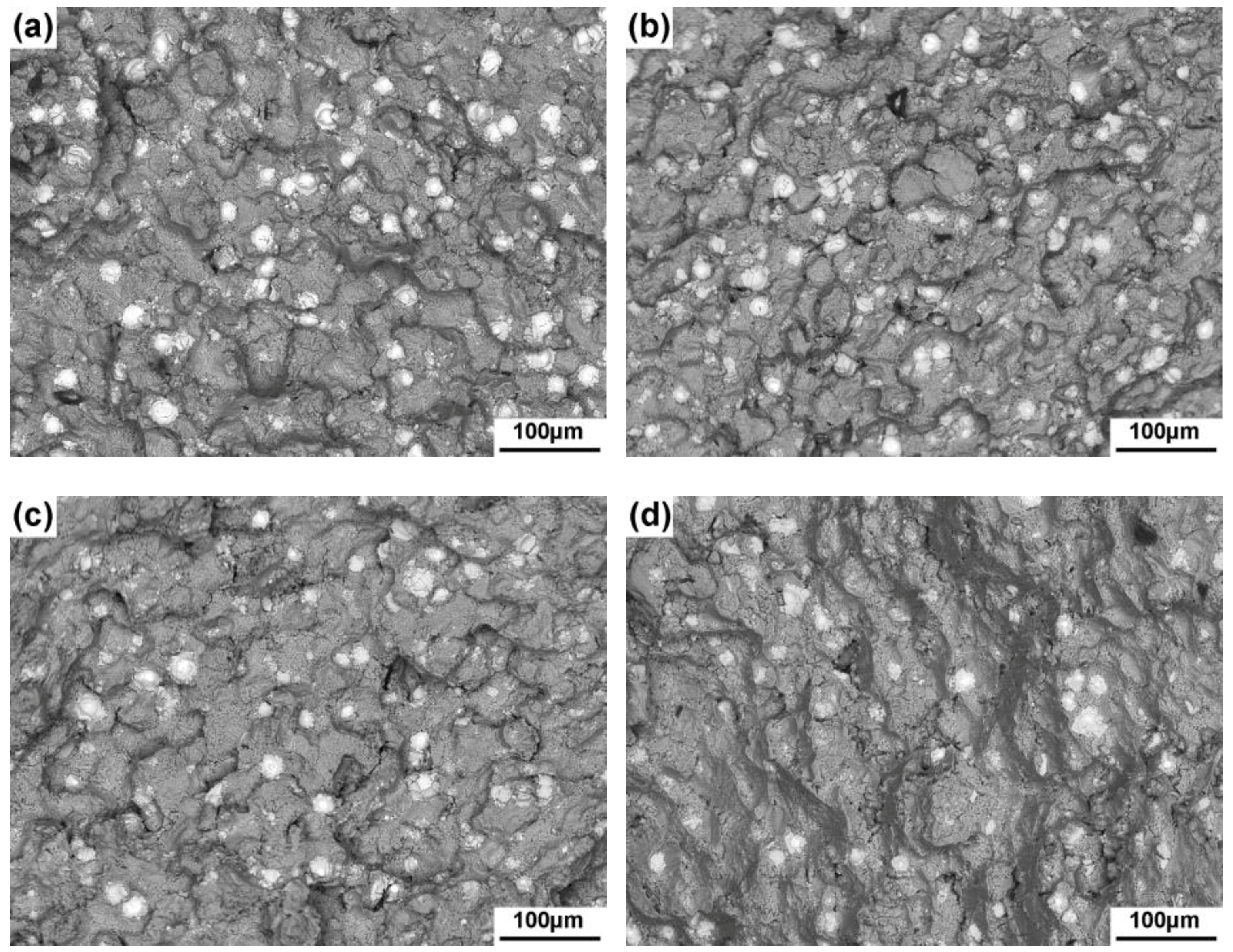
Figure 11 shows the fracture surface morphologies of the composites thixoformed at different mold temperatures. It is seen that small pores could be obviously found on the fracture surface of the composite formed at 150 °C (marked by arrows A in Figure 11a). This demonstrated that porosities generated in this composite. Considering the solidification process during thixoforming, porosities could only generate in the SSSs between the primary particles, and thus the SSSs were the weak points of this composite. So cracks preferentially developed along these structures during tensile testing, resulting in the intergranular fracture (Figure 12a). As the temperature rose to 200 °C, no visible pores could be found and the surfaces were occupied by failed reinforcements (marked by the red circle in Figure 11b) and tearing matrix. This indicated that the microstructure actually became compact, due to the improved feeding ability from the temperature rise. Thus, the propagation path of cracks had no obvious selectivity and carried out either along the SSSs (marked by arrows A in Figure 12b) or across the primary particles (marked by arrows B in Figure 12b). But when the temperature was further elevated, pores appeared again (marked by arrows B and C in Figure 11c,d), demonstrating that the feeding ability became poor again. Correspondingly, the general fracture mode evolved into the intergranular fracture again (Figure 12c). It should be noted that the propagation could occasionally across the primary particles (marked by arrows C in Figure 12d), due to stress concentration caused by the coarsening of primary particles and the agglomeration of reinforcements when the mold temperature rose to 400 °C. In summary, as the mold temperature rose, the fracture mode of the composites changed from intergranular fracture to a mixture of intergranular and transgranular fracture, due to the improved microstructure compactness. When the temperature exceeded 200 °C, the pores appeared again in the SSSs, and the fracture regime changed into the intergranular fracture again.
As described above, the strengthening role of the reinforcing particles is realized by transferring the external load from matrix to the reinforcements [29]. A more compact-microstructure matrix can transfer higher load and the resulting composite should have a higher tensile strength. When the external load exceeded a certain degree, i.e., the load that the reinforcements bear exceeded a given degree, the reinforcements would either fracture or debond from the matrix at the interface. So it can be expected that the number of the visible reinforcements on the fracture surface can indirectly reflect the microstructure compactness, and thus, the tensile properties of the composite to some extent. As shown by Figure 13, the number of the visible reinforcements first increased as the mold temperature rose to 200 °C, and then decreased when it exceeded 200 °C. This change can be clearly seen from the quantitative statistics shown by Figure 14, and the change trend is just same to that of the tensile properties (Figure 10), and also consistent with the variation of microstructure compactness as a function of mold temperature, as discussed above.
3.3. Fracture Process of the Reinforcements and Toughening Mechanism
For a composite, the reinforcements are the most important constituent. In addition, the most obvious advantage of the present composite is its excellent ductility. Thus, the reinforcements’ behaviors during tensile testing are quite crucial to clarify the toughening mechanisms. By analyzing the fracture surfaces and in-situ tensile testing, two types of failed reinforcements, interface debonding and cracking, were found. According to the debonding positions, the interface debonding can be divided into two kinds, debonding at the interface between the shell and the Ti core (Figure 15a), and debonding at the interface between the shell and the jagged structures (Figure 15b). When the load borne by the reinforcements exceeded a given degree, the shells first cracked (as shown by arrow A in Figure 15a). A high stress concentration then generated at the interface between the shell and Ti core, due to the large difference in their stiffness, leading to crack along the interface. On the fracture surface, this failed mode always exhibited a bulge or pit morphology and there was a circle fracture shell around it (Figure 15c). However, this failed mode was quite scarce, which implied that the bonding between the shell and Ti core was quite strong. As discussed above, there was always a gap between the compact shell and jagged structures of the reinforcements and the gap was filled by Al matrix. More importantly, due to the Kirkendal effect, voids formed adjacent to Al/Al3Ti interface [30]. That is, the bonding strength between these two structures was relatively weak. So debonding from their interfaces was relatively easy when the advancing cracks encountered the reinforcements. The debonding shown by Figure 12a, c and d (marked by the red circles) just belongs to this case. In most cases, the reinforcements always fractured across their Ti cores (Figure 15d) and the failed reinforcements marked by circles in Figure 11b and Figure 12b belong to this mode. As discussed above, the debonding between the shell and Ti core was quite scarce. And the debonding along the interface between the jagged structures and shell had no benefit, and even was harmful to the ductility of the composite, because this debonding was easy to occur. So it can be suggested that the improvement of the ductility of the present composite compared with the traditional monolithic particle reinforced metal matrix composites (PRMMCs) should be related to the fracture behaviors across Ti core.
In what follows, the fracture process of the reinforcements across the Ti core was studied by in situ tensile testing on a SEM. Typical morphologies of the reinforcements during the in situ tensile testing were shown in Figure 16. Cracks were found to initiate first in the shell (Figure 16a). This suggested that both the relatively soft outside Al matrix and inner Ti core constrained the first-formed crack within the hard shell, and the cracks were distinctly smaller than those formed in the monolithic counterparts with identical size, highlighting the effectiveness of the core-shell structure of the reinforcements. When the external load reached a certain level, severe plastic deformation occurred in the Ti core. This should be followed by work hardening, which subsequently resulted in many small secondary cracks in the Ti core (marked by arrows in Figure 16b). At the same time, the two tips of the primary cracks (to differentiate from the secondary cracks in the Ti core) in the shell were obviously blunted by plastic deformation of the Ti core and Al matrix. It could be suggested that the Ti core should absorb large amount of energy through its plastic deformation and subsequent multiplying of secondary cracks in it, thus noticeably inhibiting the propagation of the primary cracks. Further increasing the external load, the primary cracks propagated across the Ti core by connecting the small secondary cracks, resulting in the fracture of the reinforcement across Ti core (Figure 16c). Overall, the excellent ductility of the core-shell particulate reinforced composites could be ascribed to the decreased crack size in the shell and the delayed crack propagation by plastic deformation and multiplication of secondary cracks in the Ti core.
4. Conclusions
- As the mold temperature rose, the primary α-Al particles coarsened and evolved into large-sized interconnected particles, due to the increased attachment growth of the secondarily primary α-Al phase and eutectic α-Al phase on the original primary particles. The core-shell structured Ti@(Al-Si-Ti)p tended to agglomerate, due to the impelling effect of the advancing interfaces of α-Al/liquid. Simultaneously, the eutectic Si phases coarsened and spheroidized. All of these changes were contributed to the decreased solidification rate.
- The tensile properties of the composite firstly increased as the mold temperature rose from 150 °C to 200 °C due mainly to the improvement of microstructure compactness and the spheroidization of eutectic Si phases, and then decreased resulting from the coarsening of both the primary particles and the eutectic Si phases, as well as the agglomeration of reinforcing particles and the deteriorated microstructure compactness. The composite thixoformed 200 °C has high tensile properties, especially an excellent elongation of 8.3%, which is higher than those of the existing as-fabricated Al3Tip/A356 matrix composites, and even the heat treated Al3Tip/A356 matrix composites.
- There were two failure modes for the core-shell structured reinforcements. One was the interface debonding either between the shell and the Ti core, or between the shell and the outside jagged structures. The other was the particle cracking across Ti core. In view of the fracture process of the reinforcements across Ti core, the excellent ductility of the composite was contributed to the decreased crack size in the shell and the delayed crack propagation by plastic deformation, and multiplication of secondary cracks in the Ti cores, which originated from the core-shell structure of the reinforcements.
Author Contributions
T.C. designed the experimental program and reviewed the manuscript; M.G. and H.Q. performed the experiments and analyzed the experiment results under the guidance of T.C.; M.G. wrote the paper.
Funding
This research was funded by the National Natural Science Foundation of China (Grant No. 51564035) and the Program for Hongliu Outstanding Talents of Lanzhou University of Technology.
Acknowledgments
The authors wish to express thanks to financial support from the National Natural Science Foundation of China (Grant No. 51564035) and the Program for Hongliu Outstanding Talents of Lanzhou University of Technology.
Conflicts of Interest
The authors declare no conflict of interest.
References
- Panwar, N.; Chauhan, A. Fabrication methods of particulate reinforced aluminium metal matrix composite—A review. Mater. Today Proc. 2018, 5, 5933–5939. [Google Scholar] [CrossRef]
- Mazahery, A.; Abdizadeh, H.; Baharvandi, H.R. Development of high-performance A356/nano-Al2O3 composites. Mater. Sci. Eng. A 2009, 518, 61–64. [Google Scholar] [CrossRef]
- Li, P.B.; Chen, T.J.; Qin, H. Effects of pressure on microstructure and mechanical properties of SiCp/2024 Al-based composites fabricated by powder thixoforming. J. Mater. Sci. 2017, 52, 2045–2059. [Google Scholar] [CrossRef]
- Huashun, Y.; Chen, H.; Sun, L.; Min, G. Preparation of Al-Al3Ti in situ composites by direct reaction method. Rare Met. 2006, 25, 32–36. [Google Scholar]
- Uan, J.Y.; Chen, L.H.; Lui, T.S. On the extrusion microstructural evolution of Al-Al3Ni in situ composite. Acta Mater. 2001, 49, 313–320. [Google Scholar] [CrossRef]
- Wang, X.R.; Guan, G.; Misra, R.D.K.; Wang, Y.; Li, H.C.; Shang, Y.Q. The mechanistic contribution of nanosized Al3Fe phase on the mechanical properties of Al-Fe alloy. Mater. Sci. Eng. A 2018, 724, 452–460. [Google Scholar] [CrossRef]
- Liu, Z.W.; Cheng, N.; Zheng, Q.L.; Wu, J.H.; Han, Q.Y.; Huang, Z.F.; Xing, J.D.; Li, Y.F.; Gao, Y.M. Processing and tensile properties of A356 composites containing in situ small-sized Al3Ti particulates. Mater. Sci. Eng. A 2018, 710, 392–399. [Google Scholar] [CrossRef]
- Saboori, A.; Pavese, M.; Badini, C.; Fino, P. Development of Al- and Cu-based nanocomposites reinforced by graphene nanoplatelets; Fabrication and characterization. Front. Mater. Sci. 2017, 11, 171–181. [Google Scholar] [CrossRef]
- Saboori, A.; Dadkhah, M.; Fino, P.; Pavese, M. An overview of metal matrix nanocomposites reinforced with graphene nanoplatelets; Mechanical, Electrical and Thermophysical properties. Metals 2018, 8, 423. [Google Scholar] [CrossRef]
- Saboori, A.; Moheimani, S.; Dadkhah, M.; Pavese, M.; Badini, C.; Fino, P. An overview of key challenges in the fabrication of Metal matrix nanocomposites reinforced by graphene nanoplatelets. Metals 2018, 8, 172. [Google Scholar] [CrossRef]
- Wang, Y.C.; Song, M.; Ni, S.; Xue, Y. In situ formed core–shell structured particle reinforced aluminum matrix composites. Mater. Des. 2014, 56, 405–408. [Google Scholar] [CrossRef]
- Xue, Y.; Shen, R.J.; Ni, S.; Song, M.; Xiao, D.H. Fabrication, microstructure and mechanical properties of Al-Fe intermetallic particle reinforced Al-based composites. J. Alloys Compd. 2015, 618, 537–544. [Google Scholar] [CrossRef]
- Guo, B.S.; Ni, S.; Shen, R.J.; Song, M. Fabrication of Ti-Al3Ti core–shell structured particle reinforced Al based composite with promising mechanical properties. Mater. Sci. Eng. A 2015, 639, 269–273. [Google Scholar] [CrossRef]
- Wang, Y.J.; Chen, T.J.; Zhang, S.Q.; Qin, Y.H.; Zhang, X.Z. Effects of partial remelting on microstructure of Al-Si-Ti bulk alloy prepared by cold pressing mixed powder. Mater. Trans. 2016, 57, 1124–1133. [Google Scholar] [CrossRef]
- Qin, Y.H.; Chen, T.J.; Wang, Y.J.; Zhang, X.Z.; Li, P. Semisolid microstructural evolution during partial remelting of a bulk alloy prepared by cold pressing of the Ti-Al-2024Al powder mixture. Materials 2016, 9, 199. [Google Scholar] [CrossRef]
- Chen, T.J.; Gao, M.; Tong, Y.Q. Effects of alloying elements on the formation of core-shell-structured reinforcing particles during heating of Al–Ti powder compacts. Materials 2018, 11, 138. [Google Scholar] [CrossRef] [PubMed]
- Hirt, G.; Cremer, R.; Witulski, T.; Tinius, H.-C. Lightweight near net shape components produced by thixoforming. Mater. Des. 1997, 18, 315–321. [Google Scholar] [CrossRef]
- Chen, T.J.; Hao, Y.; Li, Y.D.; Ma, Y. Effect of solid solution treatment on semisolid microstructure of dendritic zinc alloy ZA27. Mater. Sci. Technol. 2008, 24, 1313–1320. [Google Scholar] [CrossRef]
- Chen, T.J.; Huang, L.K.; Huang, X.F.; Ma, Y.; Hao, Y. Effects of mould temperature and grain refiner amount on microstructure and tensile properties of thixoforged AZ63 magnesium alloy. J. Alloys Compd. 2013, 556, 167–177. [Google Scholar] [CrossRef]
- Wang, Y.J. Microstructural Evolution during Partial Remelting of (Al-Si)-Al-Ti Powder Compact Prepared by Cold Pressing. Master’s Thesis, Lanzhou University of Technology, Lanzhou, China, 2016. [Google Scholar]
- Yang, R.; Zhang, Z.Y.; Zhao, Y.T.; Chen, G.; Guo, Y.H.; Liu, M.P.; Zhang, J. Effect of multi-pass friction stir processing on microstructure and mechanical properties of Al3Ti/A356 composites. Mater. Charact. 2015, 106, 62–69. [Google Scholar] [CrossRef]
- Fei, W.D.; Kang, S.B. Effects of cooling rate on solidification process in AI-Mg-Si alloy. J. Mater. Sci. Lett. 1995, 14, 1795–1797. [Google Scholar] [CrossRef]
- Sebaie, O.El.; Samuel, A.M.; Samuel, F.H.; Doty, H.W. The effects of mischmetal, cooling rate and heat treatment on the eutectic Si particle characteristics of A319.1, A356.2 and A413.1 Al–Si casting alloys. Mater. Sci. Eng. A 2008, 480, 342–355. [Google Scholar] [CrossRef]
- Kim, K.; Voorhees, P.W. Ostwald ripening of spheroidal particles in multicomponent alloys. Acta Mater. 2018, 152, 327–337. [Google Scholar] [CrossRef]
- Chatterjee, S.; Ghosh, A.; Basu Mallick, A. Understanding the evolution of microstructural features in the in situ intermetallic phase reinforced Al/Al3Ti nanocomposite. Mater. Today Proc. 2018, 5, 10118–10130. [Google Scholar] [CrossRef]
- Yang, C.C.; Liu, Z.W.; Zheng, Q.L.; Cao, Y.L.; Dai, X.H.; Sun, L.; Zhao, J.R.; Xin, J.D.; Han, Q.Y. Ultrasound assisted in-situ casting technique for synthesizing small-sized blocky Al3Ti particles reinforced A356 matrix composites with improved mechanical properties. J. Alloys Compd. 2018, 747, 580–590. [Google Scholar] [CrossRef]
- Hong, S.H.; Chung, K.H. Effects of vacuum hot pressing parameters on the tensile properties and microstructures of SiC-2124 A1 composites. Mater. Sci. Eng. A 1995, 194, 165–170. [Google Scholar] [CrossRef]
- Liu, Z.Y.; Xiao, B.L.; Wang, W.G.; Ma, Z.Y. Analysis of carbon nanotube shortening and composite strengthening in carbon nanotube/aluminum composites fabricated by muli-pass friction stir processing. Carbon 2014, 69, 264–274. [Google Scholar] [CrossRef]
- Wang, M.L.; Chen, D.; Chen, Z.; Wu, Y.; Wang, F.F.; Ma, N.H.; Wang, H.W. Mechanical properties of in-situ TiB2/A356 composites. Mater. Sci. Eng. A 2014, 590, 246–254. [Google Scholar] [CrossRef]
- Tavoosi, M. The Kirkendall void formation in Al/Ti interface during solid-state reactive diffusion between Al and Ti. Surf. Interfaces 2017, 9, 196–200. [Google Scholar] [CrossRef]
Figure 1.
Dimensions of (a) tensile and (b) in situ tensile test specimens (in mm).
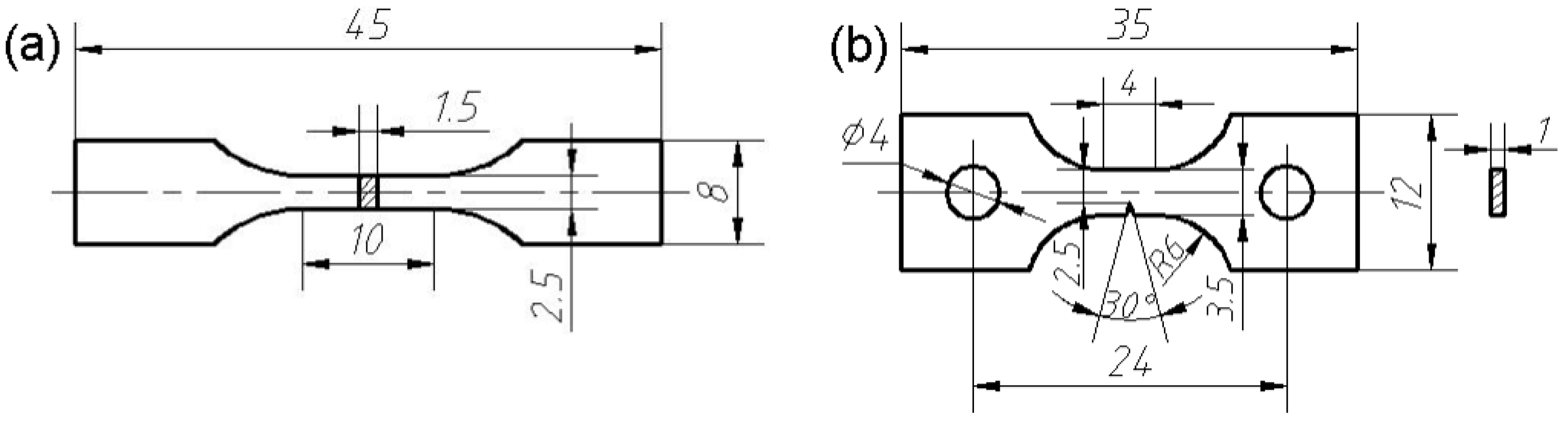
Figure 2.
Optical microscope (OM) images of the composites thixoformed under mold temperatures of (a) 150 °C, (b) 200 °C, (c) 300 °C, and (d) 400 °C. Insert in (a) showing the secondarily solidified structures among the primary particles.
Figure 2.
Optical microscope (OM) images of the composites thixoformed under mold temperatures of (a) 150 °C, (b) 200 °C, (c) 300 °C, and (d) 400 °C. Insert in (a) showing the secondarily solidified structures among the primary particles.
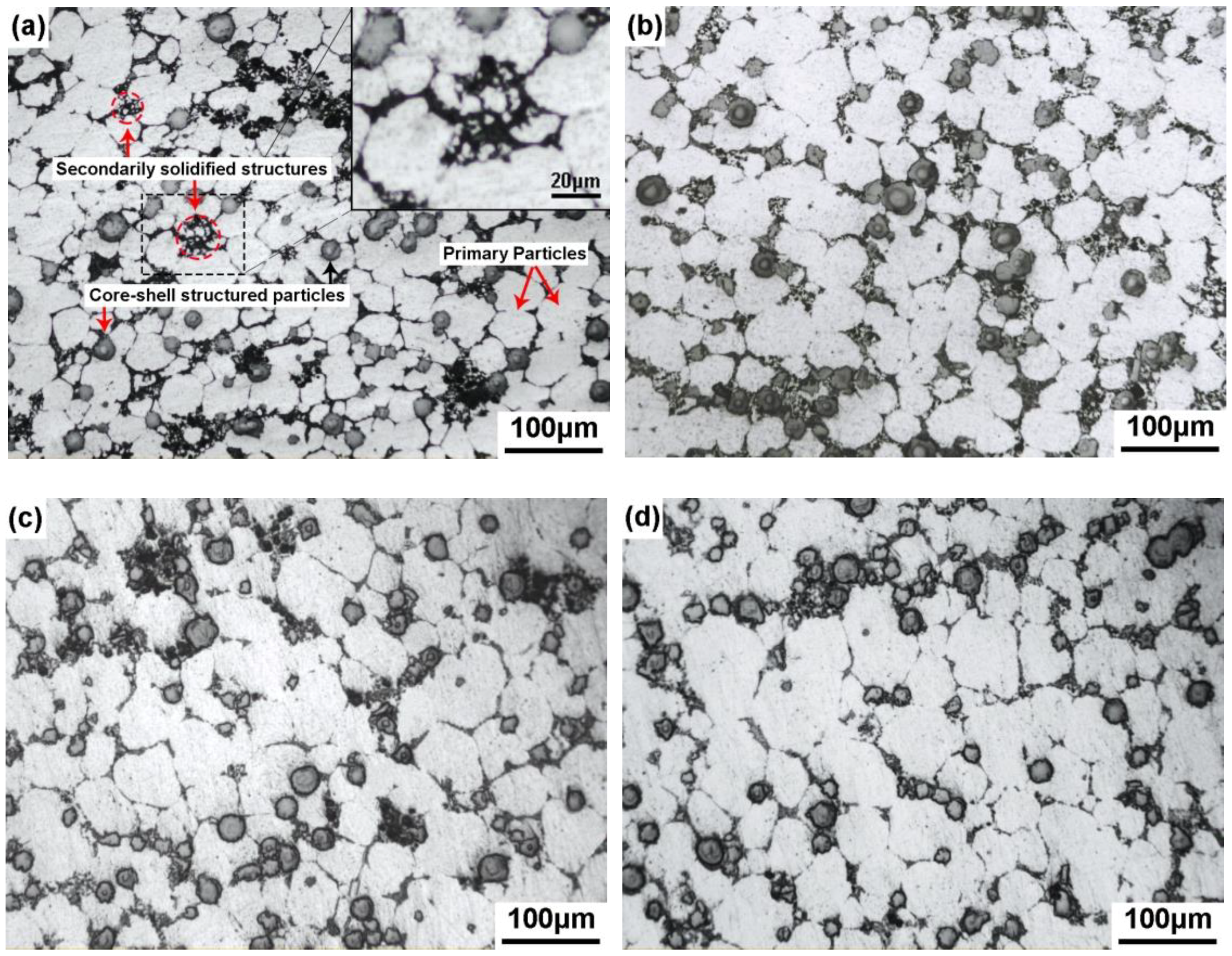
Figure 3.
Variation of primary particle size with mold temperature.
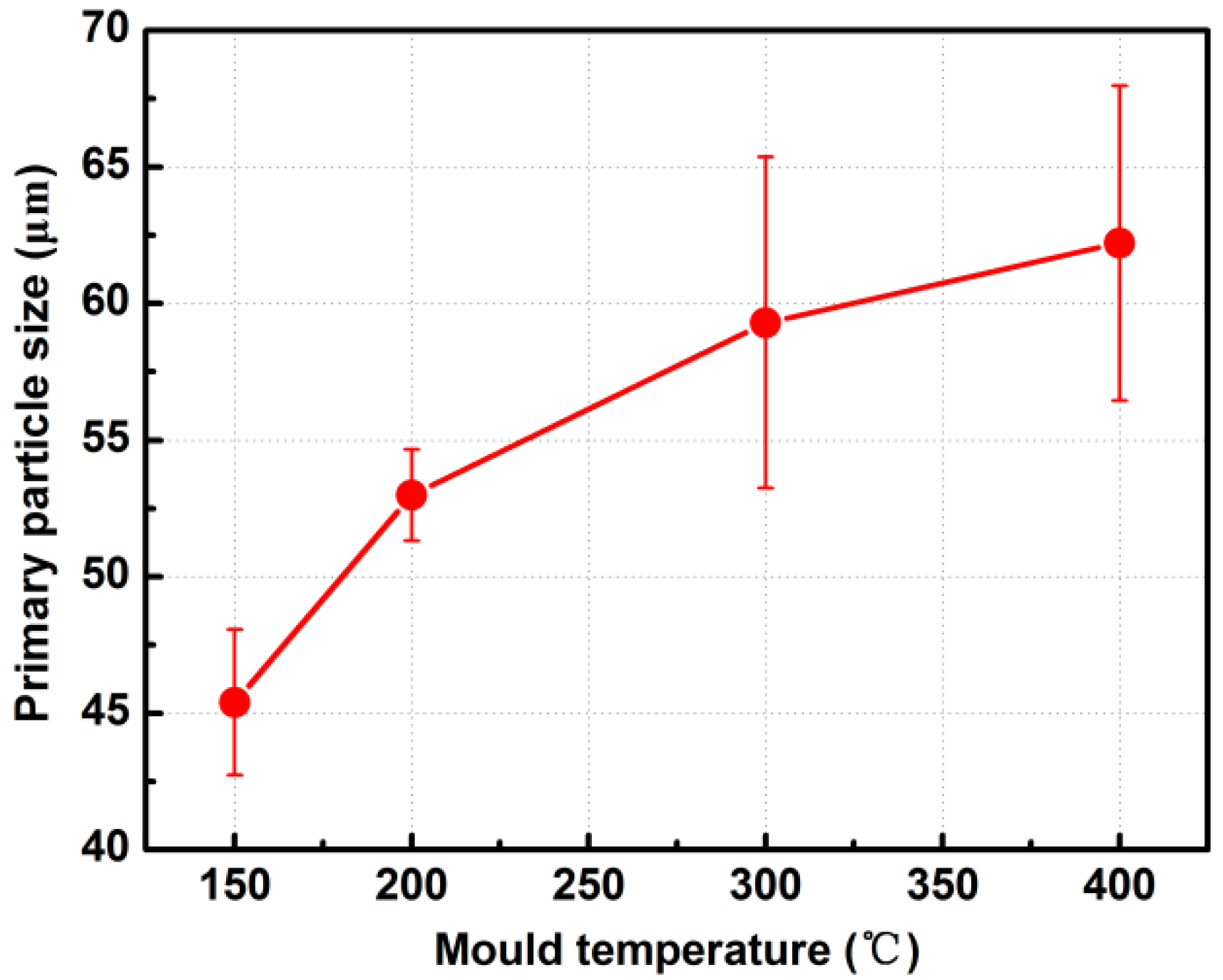
Figure 4.
OM image of the A356 matrix alloy.
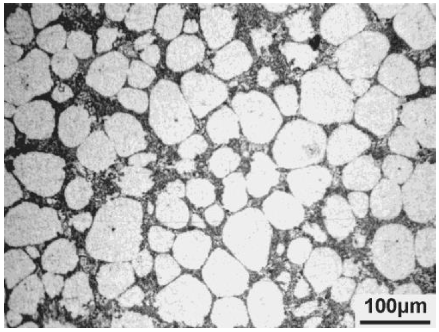
Figure 5.
Scanning electron microscope (SEM) images of eutectic Si phases in the composites thixoformed under mold temperatures of (a) 150 °C, (b) 200 °C, (c) 300 °C, and (d) 400 °C. Insert in (d) showing another kind of morphology of the eutectic Si phases.
Figure 5.
Scanning electron microscope (SEM) images of eutectic Si phases in the composites thixoformed under mold temperatures of (a) 150 °C, (b) 200 °C, (c) 300 °C, and (d) 400 °C. Insert in (d) showing another kind of morphology of the eutectic Si phases.
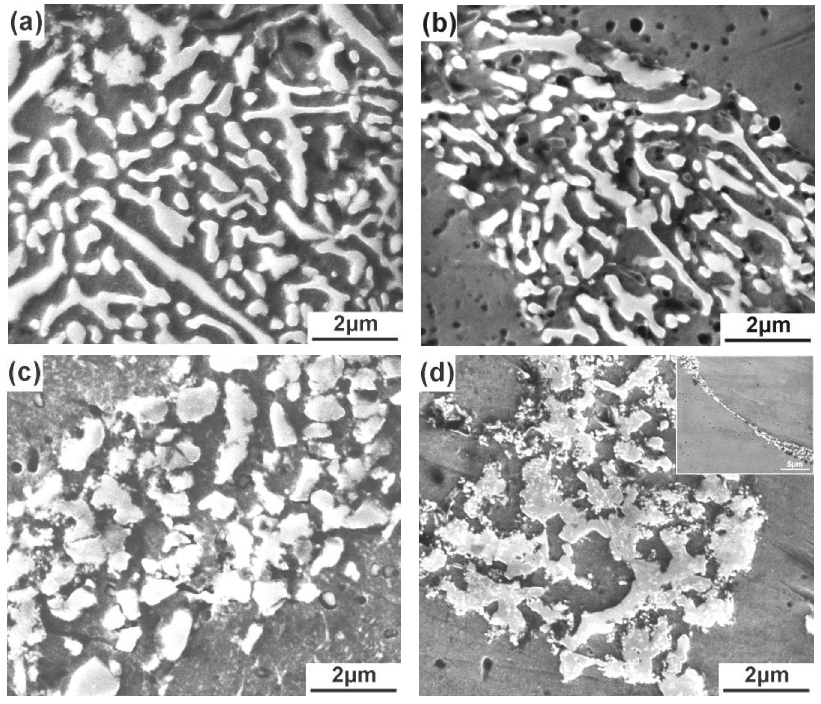
Figure 6.
Variations of the length and width of eutectic Si phases with mold temperature.
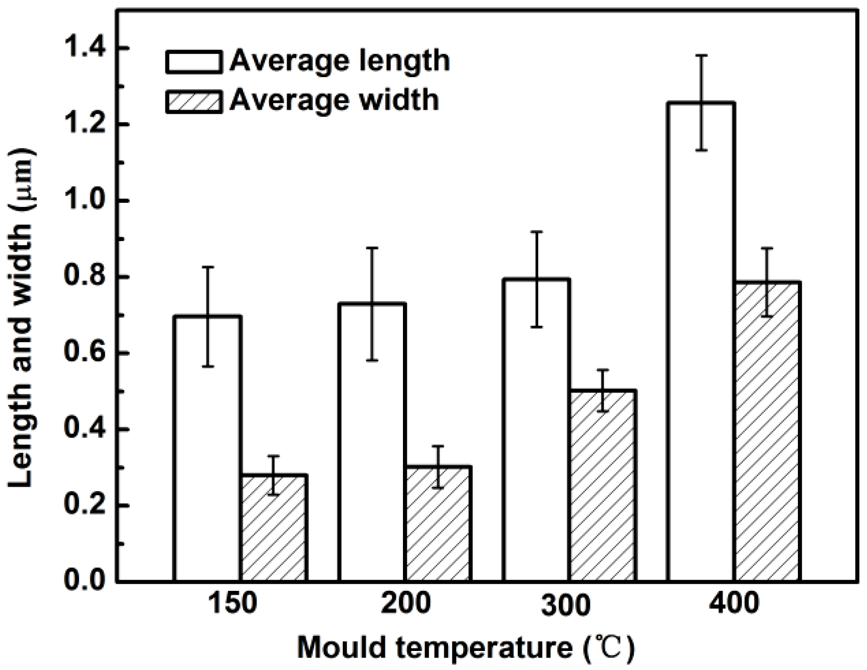
Figure 7.
SEM images and energy dispersive spectroscope (EDS) results of reinforcing particles in the composites thixoformed under mold temperatures of (a) 150 °C, (b) 400 °C.
Figure 7.
SEM images and energy dispersive spectroscope (EDS) results of reinforcing particles in the composites thixoformed under mold temperatures of (a) 150 °C, (b) 400 °C.
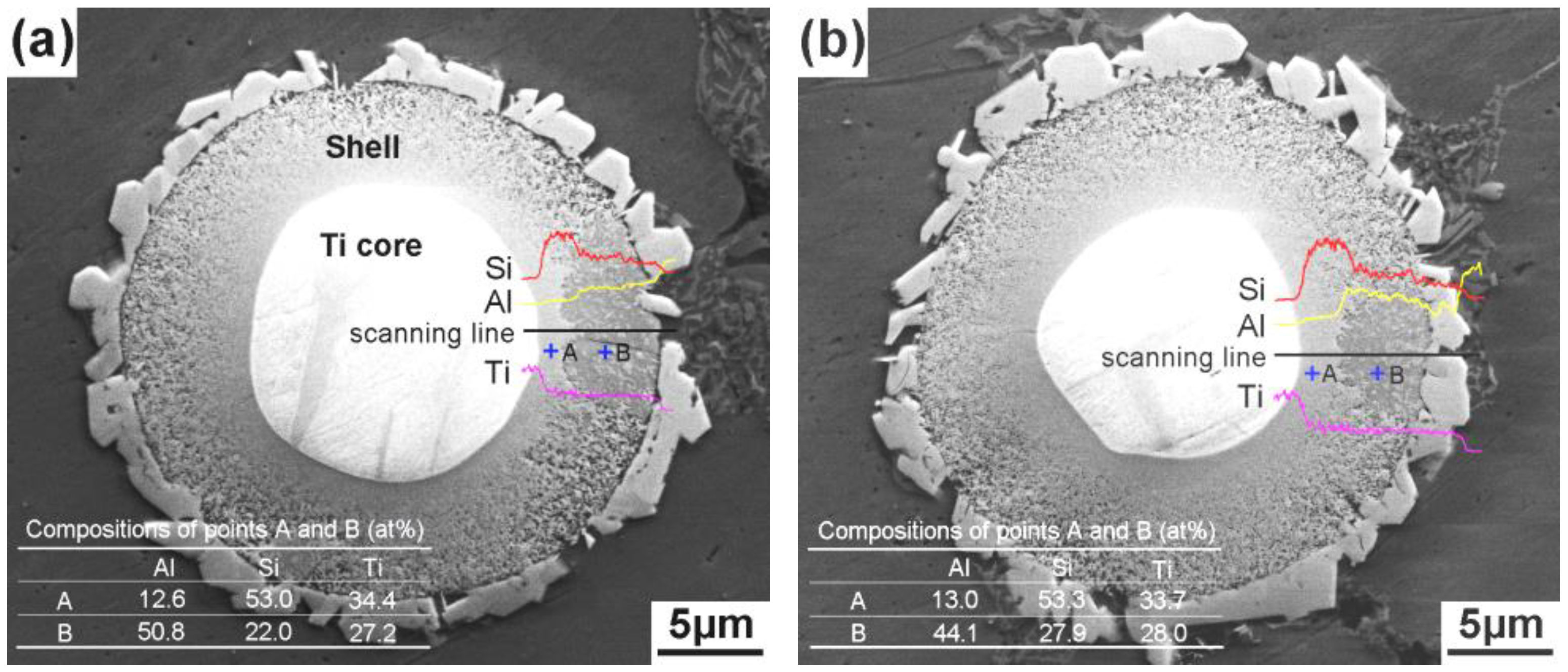
Figure 8.
X-ray diffraction (XRD) patterns of the composites thixoformed under mold temperatures of 150 °C and 400 °C.
Figure 8.
X-ray diffraction (XRD) patterns of the composites thixoformed under mold temperatures of 150 °C and 400 °C.
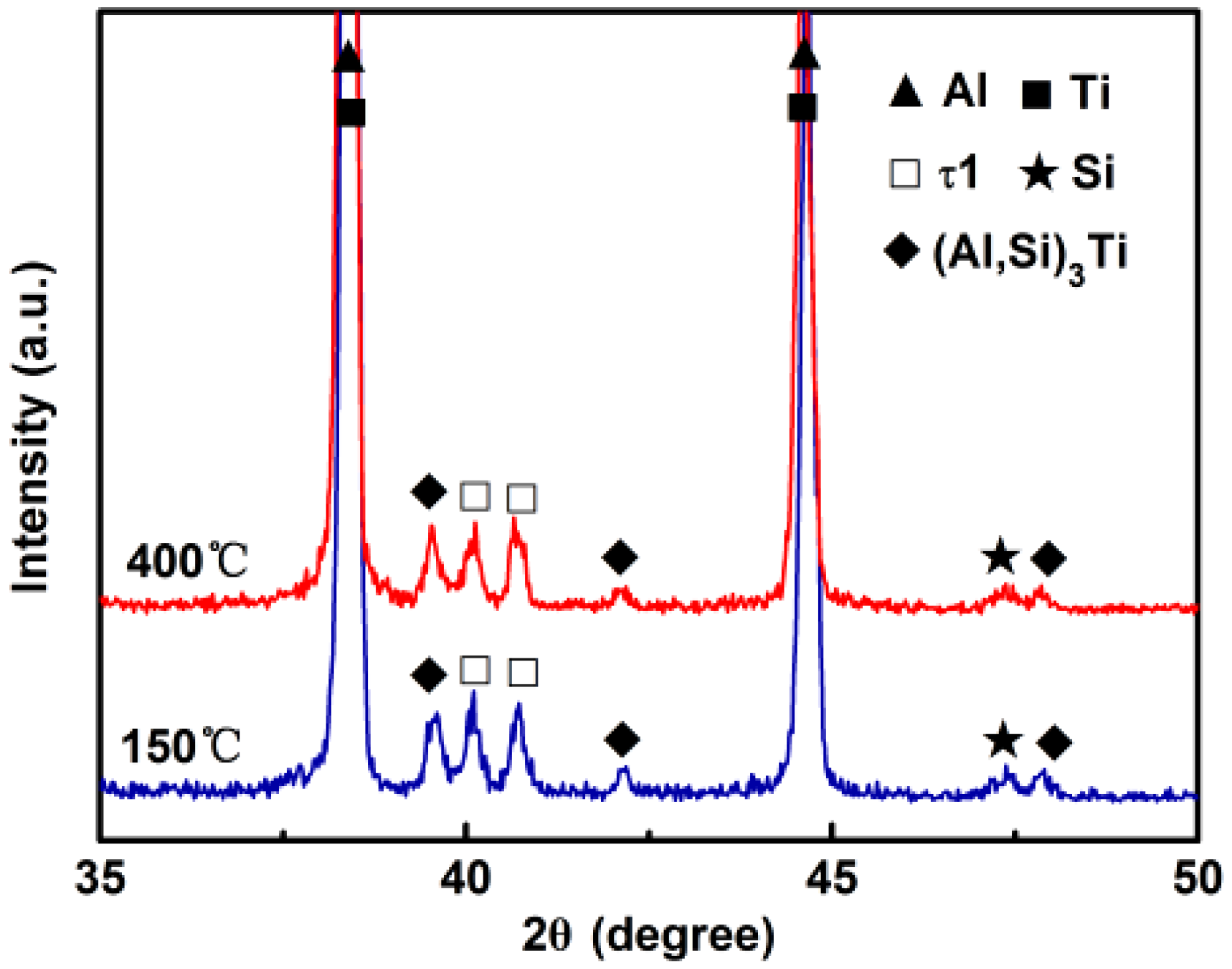
Figure 9.
Morphology of a reinforcement in the composite formed at mold temperature of 400 °C.
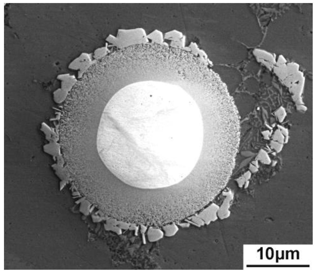
Figure 10.
Variations of tensile properties of the composite with mold temperature.
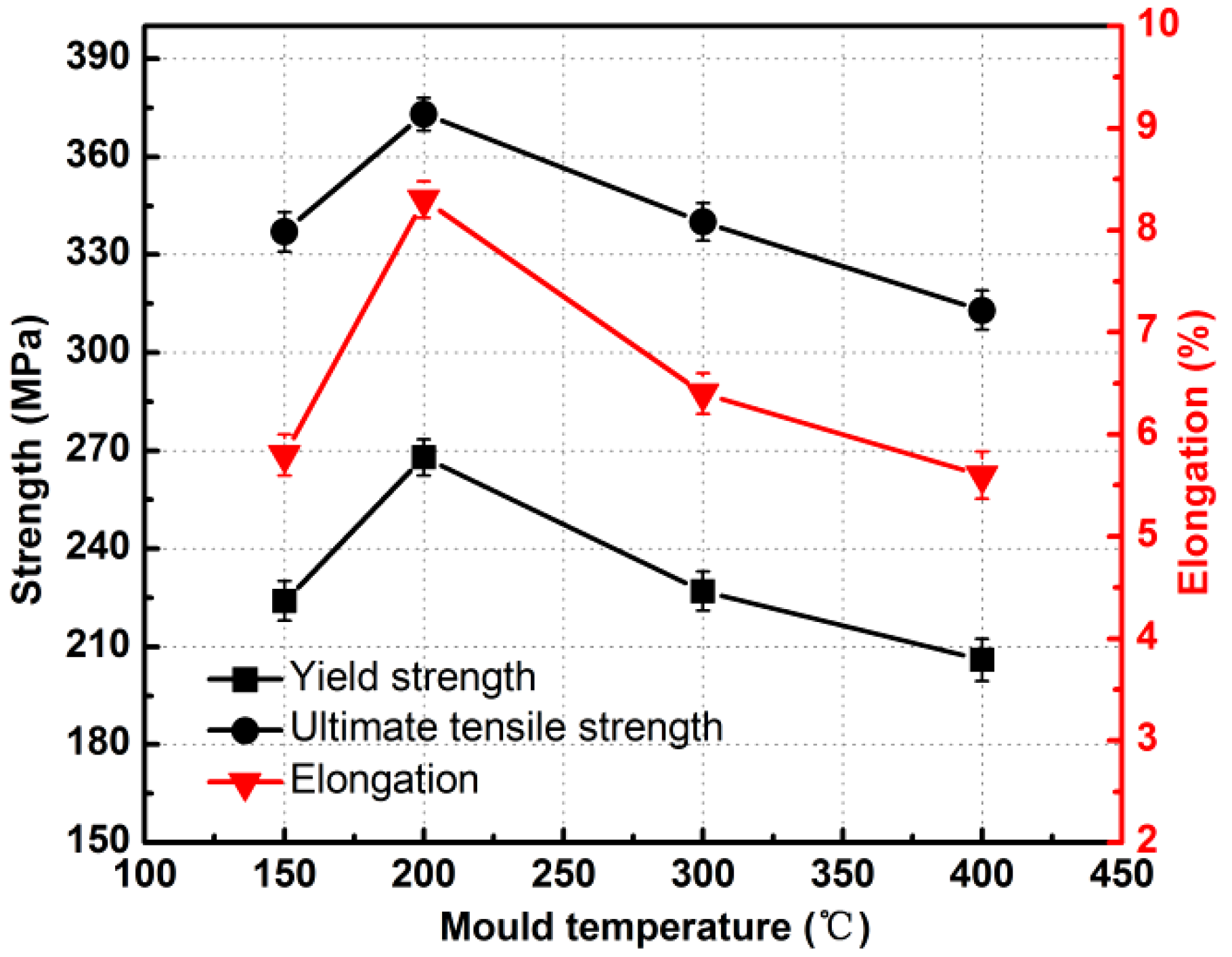
Figure 11.
Fractographs of the composites thixoformed at mold temperatures of (a) 150 °C, (b) 200 °C, (c) 300 °C, and (d) 400 °C.
Figure 11.
Fractographs of the composites thixoformed at mold temperatures of (a) 150 °C, (b) 200 °C, (c) 300 °C, and (d) 400 °C.
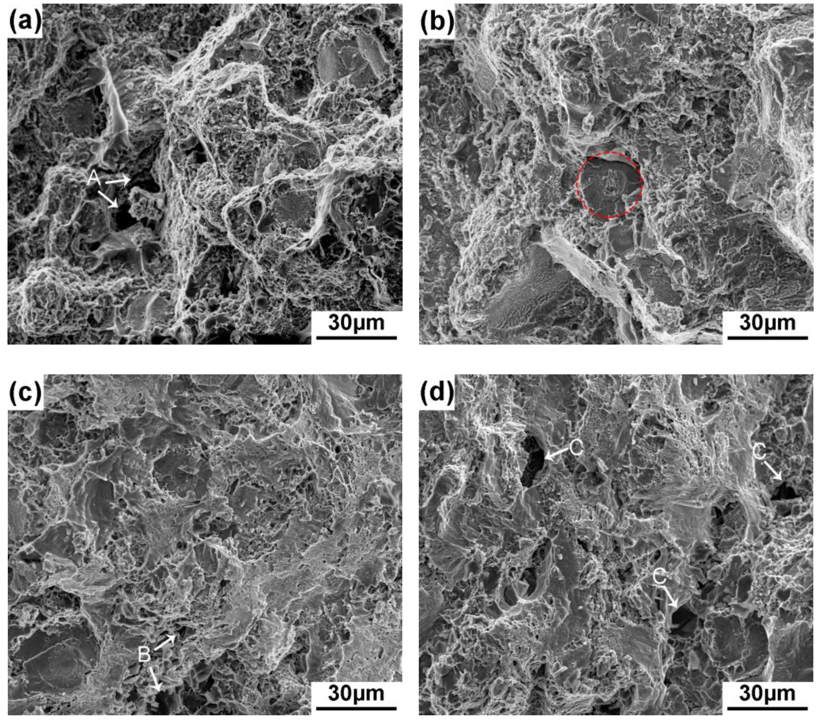
Figure 12.
Side views of fracture surfaces of the composites thixoformed at mold temperatures of (a) 150 °C, (b) 200 °C, (c) 300 °C, and (d) 400 °C.
Figure 12.
Side views of fracture surfaces of the composites thixoformed at mold temperatures of (a) 150 °C, (b) 200 °C, (c) 300 °C, and (d) 400 °C.

Figure 13.
BSE images of fracture surfaces of the composites thixoformed under mold temperatures of (a) 150 °C, (b) 200 °C, (c) 300 °C, and (d) 400 °C.
Figure 13.
BSE images of fracture surfaces of the composites thixoformed under mold temperatures of (a) 150 °C, (b) 200 °C, (c) 300 °C, and (d) 400 °C.

Figure 14.
Visible reinforcement number on the fracture surfaces of the composites thixoformed at different mold temperatures.
Figure 14.
Visible reinforcement number on the fracture surfaces of the composites thixoformed at different mold temperatures.
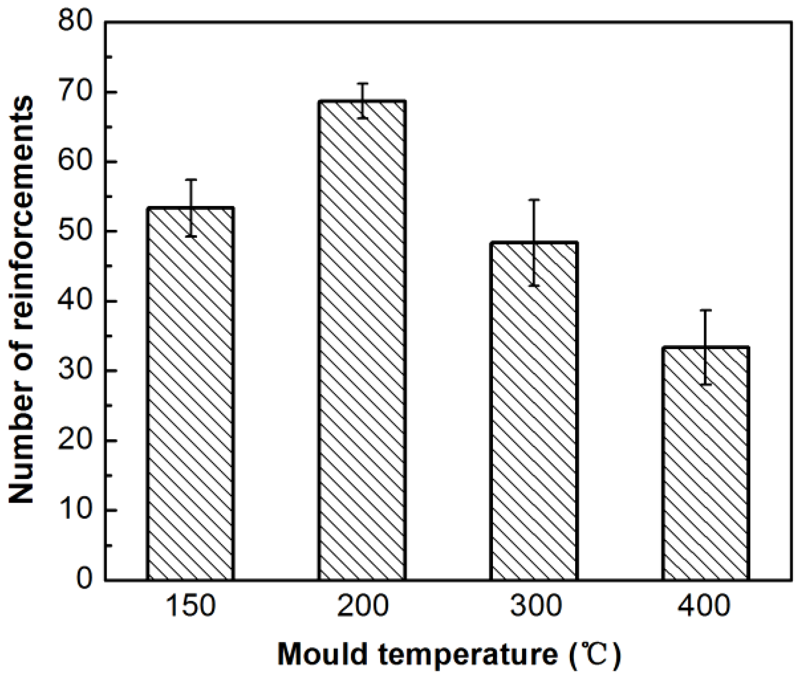
Figure 15.
SEM micrographs of the failed reinforcements.

Figure 16.
SEM micrographs of core-shell-structured reinforcements in the composite thixoformed at 200 °C showing the fracture process during in situ tensile testing.
Figure 16.
SEM micrographs of core-shell-structured reinforcements in the composite thixoformed at 200 °C showing the fracture process during in situ tensile testing.


Table 1.
Porosities of the composites thixoformed under different mold temperatures.
| Mold Temperature, °C | 150 | 200 | 300 | 400 |
|---|---|---|---|---|
| Porosity, % | 2.037 ± 0.276 | 0.988 ± 0.008 | 1.230 ± 0.215 | 2.434 ± 0.100 |
© 2018 by the authors. Licensee MDPI, Basel, Switzerland. This article is an open access article distributed under the terms and conditions of the Creative Commons Attribution (CC BY) license (http://creativecommons.org/licenses/by/4.0/).
Share and Cite
MDPI and ACS Style
Gao, M.; Chen, T.; Qin, H. Effects of Mold Temperature on the Microstructure and Tensile Properties of Ti@(Al-Si-Ti)p/A356 Composite Prepared via Powder Thixoforming. Metals 2018, 8, 829. https://doi.org/10.3390/met8100829
AMA Style
Gao M, Chen T, Qin H. Effects of Mold Temperature on the Microstructure and Tensile Properties of Ti@(Al-Si-Ti)p/A356 Composite Prepared via Powder Thixoforming. Metals. 2018; 8(10):829. https://doi.org/10.3390/met8100829
Chicago/Turabian StyleGao, Min, Tijun Chen, and He Qin. 2018. "Effects of Mold Temperature on the Microstructure and Tensile Properties of Ti@(Al-Si-Ti)p/A356 Composite Prepared via Powder Thixoforming" Metals 8, no. 10: 829. https://doi.org/10.3390/met8100829
Note that from the first issue of 2016, this journal uses article numbers instead of page numbers. See further details here.