Surface Modification of Q195 Structure Carbon Steel by Electrolytic Plasma Processing

State Key Laboratory for Advanced Metals and Materials, University of Science and Technology Beijing, Beijing 100083, China
*
Author to whom correspondence should be addressed.
Metals 2018, 8(10), 831; https://doi.org/10.3390/met8100831
Submission received: 15 September 2018
/
Revised: 4 October 2018
/
Accepted: 12 October 2018
/
Published: 16 October 2018
Abstract
:In this study, we applied an emerging, environmentally friendly surface engineering technology, electrolytic plasma processing (EPP), for the surface modification of Q195 structure carbon steel surface pretreatment and further Zn coating. Treating the surfaces of Q195 structure carbon steel by EPP was a quite dynamic process, which was investigated using scanning electron microscopy (SEM), energy dispersive spectroscopy (EDS), and X-ray diffraction (XRD). The results shown that surface scale can be effectively remove after 40 s EPP treatment, and the EPP-treated Q195 structure carbon steel revealed a slight decrease in elastic modulus and hardness, but a substantial improvement in tensile (especially plastic) mechanical properties. Moreover, the further EPP modification conducted on the pretreated Q195 structure carbon steel sample for production of a layer of compact zinc coating with 15 μm thickness under an optimization EPP process. We also identified the modification mechanism of EPP to Q195 structure carbon steel, which may provide theoretical and practical guidance for future researchers and developers.

1. Introduction
Q195 structure carbon steel has garnered substantial research interest as a potential engineering material that is currently widely applied in the automobile industry. The material has unique properties such as high plasticity, toughness, and welding performance, as well as good deformation ability under high pressure [1,2], but requires surface modification before it can be efficiently applied in practice. Indeed, advanced modification technologies can greatly improve specific surface topographies and roughness, dramatically boost energy efficiency, and improve product performance and quality [3,4,5,6,7,8].
Surface modification is typically applied in order to obtain certain surface topographies and an appropriate amount of roughness to improve adhesion during bonding. Acid cleaning is commonly employed to remove oxides and contamination from metal materials to obtain clean and uniform surface finishes for industrial application [9,10,11]. However, acidic solutions introduce several drawbacks, such as corrosion to the material and environmental pollution. In addition, some surface modification methods, such as cathodic protection, fabrication of protective coatings, and use of corrosion inhibitors have advanced to the point of becoming actually useful for practical applications in the near future [12,13,14,15]. However, those methods involve complex multistep processing procedures, low efficiency, and high cost, which greatly limit their practical applications. Therefore, to find a simple and effective method that can attain Q195 structural carbon steel with rough surfaces is highly desired, and very favorable for the future coating.
Electrolytic plasma processing (EPP) technology can vastly boost energy efficiency and improve product performance and quality, while consuming relatively little energy and producing relatively few environmental pollutants; it is an important potential alternative cleaning process or galvanization technique, to this effect [16,17,18,19,20,21,22,23,24,25,26,27,28]. But there is a general lack of research on the interactions between EPP and the surface of Q195 structure carbon steel, which limits its further large-scale industrial production. In this work, we adopted EPP technology to surface modification of Q195 structural carbon steel, and the results show that Q195 structural carbon steel with a uniform surface and favorable properties was attained by the sample and processed within optimal parameters. Moreover, a layer of compact zinc coating with 15 µm thickness could be formed on the surface by EPP treatment. The deposition mechanism of the Zn coatings and the effect of EPP parameters are also described. We hope that this paper may serve as theoretical and practical guidance for the further development and industrial production application of EPP.
2. Experimental Procedure
2.1. Q195 Structural Carbon Steel Sample Preparation
The Q195 structural carbon steel with uniform diameter of about 2 mm (C ≤ 0.12, Mn ≤ 0.50, Si ≤ 0.30, S ≤ 0.040, P ≤ 0.035) used in this study was purchased from Baosteel Group Corp (Shanghai, China). Sodium bicarbonate and zinc sulfate were purchased from J & K Chemical Technology (Beijing, China). The experimental power source and electrode device was configured as shown in Figure 1. The electrolyzer consists of a 120 × 80 × 50 cm3 propene polymer container, an anode supply connected with two parallel graphite plates, and the suspending workpiece; the Q195 structural carbon steel sample served as the cathode. All saturated solution of sodium bicarbonate was prepared with ultra-pure MilliQ water (resistance > 18 MΩ cm−1).
2.2. Instruments
A TN-KGZ01 high frequency switching PC power supply (CHEGDU JINCHUANGLI SCIENCE & TECHNOLOGY CO., LET, Sichuan province, China) was used to provide the energy for plasma formation. The surface morphology microstructure of the steel samples was analyzed by field emission scanning electron microscopy (German ZEISS SUPRA55-FESEM, Carl Zeiss AG, Jena, Germany) and X-ray diffraction analysis (Rigaku D/MAX-2500-H, Rigaku, Tokyo, Japan) was conducted to determine the qualitative phases of the Q195 structural carbon steel (rectangle, with size of 10 × 5 × 2 mm3) before and after EPP. The mechanical properties (elastic modulus and hardness) of the steel was tested with a Nano Indenter II Nano probe (Techcomp, Beijing, China), and tensile mechanical properties were examined with a Strang Instron 5980 series double column tensile machine (Instron, Boston, MA, USA) on the floor.
2.3. Q195 Structural Carbon Steel Treatment by EPP
2.3.1. Configuration of Sodium Bicarbonate Saturated Solution
We prepared the saturated sodium bicarbonate solution by first pouring 500 L deionized water into a propene polymer container, then slowly stirring in 100 g sodium bicarbonate.
2.3.2. EPP Treatment Process
For EPP surface modification, we quickly fixed the Q195 structural carbon steel sample to the test rig and heated the sodium bicarbonate saturated solution to 70 °C. We set the input voltage to 120 V, current to 200 A, duty ratio to 80%, and the distance between two electrodes to 5 cm. The power switch and temperature measuring device were flipped on, then electrolysis plasma discharge appeared, and the temperature of the liquid environment was tested by a thermocouple probe.
2.3.3. Sample Post-Processing
The Q195 structural carbon steel was treated under optimal processing conditions with different time intervals: 10 s, 20 s, 30 s, 40 s, or 80 s. The samples were washed with water and ethanol three times each under ultrasound and dried in the oven (60 °C) for 2 h prior to further analysis.
2.3.4. Preparation of Zinc-Coated Q195 Structural Carbon Steel
For the formation of zinc coating, the samples described above were then treated with 15 wt % ZnSO4 solution for 60 s before coating. And then, the zinc film thickness was controlled by adjusting the preset electrical potentials to 150 V and 180 V, respectively, for 60 s treatment.
3. Results and Discussion
In this section, we focus on the relationship between the electrolytic plasma formation mechanism and the plasma’s interaction with the surface of Q195 structure carbon steel. Some factors that can affect plasma production are discussed in detail, as well as our analysis of EPP-treated and zinc-coated Q195 structure carbon steel samples.
3.1. Characterization of Electrolytic Plasma Processing
The mechanism of electrolytic plasma processing can be described by an electron avalanche model, mainly involving the following four processes: (1) production of a low density area in the vicinity of the workpiece surface in the electrolyte; (2) low density area gradually expanded to the critical value of electron impact ionization; (3) free electron acceleration in the form of an avalanche in strong electric field and quickly growth in exponential function, formation of ionization area; and (4) ionization region to further expand, forming arc discharge caused by synergy of electron impact fever, liquid density decrease, avalanche development, and delay effect [28]. We identified several distinct physical processes involved in EPP surface modification and subsequent zinc-coating. The input voltage, temperature, and distance between cathode and anode were of note in particular, as they affected the formation of electrolytic plasma.
As shown in Figure 1, a strong electric field was formed across the electrode gap when the electrolyte flowed through the perforated anode onto the cathode. A hydrogen evolution reaction began at the surface of the workpiece at that time, which created hydrogen bubbles and generated hydrogen plasma in a thin layer just above the sample surface. The bulb generation and extinction created forceful pressure disruptions at the surface associated with bubble collapse and shock wave production, which effectively reduced or removed the oxides and contamination at the steel surface. Rapid quenching in the water may also have resulted in ultra-fine grained structures in the steel responsible for its enhanced tensile mechanical properties. Metal cations present in the electrolyte film began to migrate toward the sample surface during zinc coating, but most of the ions were attached to the hydrogen bubbles; those metal ions reached the steel surface via hydrogen bubble adsorption transport and subsequent collapse. This caused zinc coating to form continuously and at a high rate over the entire sample surface.
Figure 2 shows an electrode voltage-duty cycle curve of the liquid electrolysis plasma processing, and suitable processing parameters for liquid electrolytic plasma formation at pulse frequency of 4000 Hz are given. When the duty cycle was high, cations were difficult to reach the Q195 structure carbon steel surface due to the ion channel was blocked by the Q195 structure carbon steel (cathode) surface hydrogen bubbles. Conversely, plasma cannot form under duty cycle lower than the bottom limit, because normal electrolysis would happen on the surface of the Q195 structure carbon steel (cathode).
3.2. Surface Microstructural Morphology Analysis
Electrolytic plasma processing is used for removing oxide scale and contaminants on Q195 structure carbon steel surface and subsequent zinc coating. By analyzing the Q195 structure carbon steel surface morphology after EPP treatment at various processing times, we found that plasma treatment was a quite dynamic process. The morphological features of samples were, as mentioned above, observed via FESEM. As shown in Figure 3a, the carbon steel surface before EPP was covered in dirt and impurities. There was no arc plasma reaction before 15 s of EPP, and as a result, the treatment appeared to have relatively little influence on the sample. At this stage, electric heating increased the electrolyte temperature and created a large quantity of bubbles; in accordance with Ohm’s law, the sample resisted it and the surrounding electrolyte liquid was heated. There was stable plasma formation on the sample surface after EPP for 15 s, at which time the superficial dirt and impurities began to decompose and fall off of the sample. These observations suggest that the edge or the tip of the sample exhibited point discharge phenomena. Yamada et al. observed similar phenomena while observing a microwave plasma discharge process characterized by energy release and gas pressure state [29]. They indicated clearly that uneven plasma density distribution in the plasma generates an electric field, which in turn leads to a substrate surface electric field and uneven distribution of temperature and gas flow at the surface. Figure 3a depicts the FESEM images of the Q195 structural carbon steel before EPP treatment. It can be observed that irregular oxide scale cover the Q195 structural carbon steel surface. After 20 s of EPP treatment, the surface of the Q195 structural carbon steel was fairly clean as shown in Figure 3b. As treatment time increased, the steel surface became smoother and began to exhibit micrometer-scale pores as shown in Figure 3c. The optimal treatment performance was observed at 40 s, at which point there was a large amount of micrometer-scale pores (Figure 3d) which dramatically increased the specific surface area and surface roughness of the carbon steel sample. As shown in Figure 3e, the plasma continued to impact EPP surface modification after 60 s, at which point both microstructure and micrometer-scale pores were eroded. Figure 3f shows the sample treated with EPP for 80 s, where all micrometer-scale pores were destroyed completely and the surface layer of the carbon steel was covered in black residue that had begun to flake off. The black holes distributed on the surface are discharge channels like those shown in Figure 3, which are similar to those observed by Cai et al. [30]. The liquid melt had cooled and accumulated a “slope trace” around the discharge holes to make the entire surface uneven. As reaction time increased, the size of the discharge channels increased and the quantity within unit area decreased. Homogeneous gas film coverage and breakdown voltage are, evidently, two crucial parameters of liquid phase plasma formation; further, the solution volatilization caused by joule heat and the solution hydrodynamic instability caused by solvent electrolysis are crucial mechanisms of plasma formation [31,32,33,34,35].
3.3. X-ray Diffraction (XRD) Pattern Characterization
The XRD pattern of Q195 carbon structural steel before and after 40 s EPP treatment are collected in Figure 4. We found that the oxide scale of Q195 carbon structural steel was fully removed off with 40 s EPP treatment. Initially, Fe2O3 peak at 23.9°, 32.8°, 35.3° and 53.8° as well as FeO peak at 40.6° and Fe3O4 peak at 56.9° and 78.9° apparently occur in the diffractogram of the untreated Q195 carbon structural steel. The diffraction peaks of the Fe2O3, FeO, and Fe3O4 all disappeared after 40 s EPP treatment, at this moment almost all the diffraction peaks of the sample can be indexed to metallic phase of Fe. This indicates that surface scale of Q195 carbon structural steel can be successfully removed after 40 s EPP treatment.
3.4. Mechanical Properties Testing
3.4.1. Fracture Morphology Characterization
As shown in Figure 5a–c, the fracture mode of Q195 structural carbon steel was ductile fracture, and numerous dimples are observed from scanning electron microscopy (SEM) photographs; Figure 5d–f show that the fracture morphology was similar to that observed for untreated samples. These results altogether indicate that the fracture morphology of Q195 structural carbon steel was generally constant before and after EPP, further suggesting that modification occurred only on the surface of the sample and did not alter the fracture mechanism of the material.
3.4.2. Tensile Mechanical Properties
The mechanical properties of a Q195 carbon structural steel surface was elevated affected by high temperature and strong shock waves induced by electrolytic plasma processing [35]. The high frequency quenching of EPP benefitted grain refinement and the formation and annihilation of micro gas film generated by the shock wave released surface stress, resulting in enhanced mechanical properties in the sample. The tensile mechanical property analysis results are shown in Figure 6, where the engineering stress-strain curve of the steel after treatment indicates higher values, i.e., better mechanical (especially plastic) properties than the untreated steel.
3.4.3. Elastic Modulus and Hardness
In order to quantitatively characterize the effect of EPP on the surface mechanical property of Q195 structural carbon steel, a nanoindentation testing was employed to measure the elastic modulus and hardness of the Q195 structural carbon steel, and the corresponding data are summarized in Figure 7 and Table 1. The results shown that EPP affected the surface mechanical property of Q195 structural carbon steel, and both of elastic modulus and hardness decreased slightly after EPP treatment for 40 s. This occurred because of uneven plasma density distribution in plasma generates an electric field, as well as uneven temperature reaction gas flow distribution on the surface of the Q195 structural carbon steel, which led to whole surface structures grew loose and porous after EPP treatment. In addition, the thermal impact cause by EPP and electrolytic hardening may have damaged the surface mechanical to some degree.
3.5. Zinc-Coating Preparation
As shown in Figure 8, the XRD pattern of Q195 structure carbon steel with 40 s EPP treatment and the sample after deposited zinc coating. There are some peaks of ZnO besides pure Zn and that is in consistent with EDS results form Table 2. In addition, no Fe substrate phase can be found after deposited zinc coating indicating that a layer of compact zinc coating cover the surface of Q195 structure carbon steel.
During the coating process, as described above, zinc cations present in the electrolyte film migrated toward the steel surface via hydrogen bubble adsorption transport and subsequent collapse. This caused zinc coating to continuously form at high rate over the entire sample surface. We found that the steel sample treated with EPP for 40 s had an optimal matrix due to its high surface roughness and homogeneous porosity. As shown in Figure 9a, after the sample was processed under 150 V applied voltage for 60 s, there was a layer of loose zinc coating with needle-like dendritic structure on the sample surface. The content of zinc atoms was 68.42% (Table 2) alongside quantities of Fe, C, and Si, indicating that the zinc layer did not completely cover the surface. Figure 9c also suggested that 5 µm of loose zinc coating was obtained by 60 s EPP treatment under 150 V applied voltage. On the contrary, Figure 9b shows that a layer of compact zinc coating formed on the surface when the sample was processed under 180 V applied voltage for 60 s; the entire surface was relatively uniform and zinc content reached 96.93%, suggesting that it had a homogeneously distributed elemental surface composition (Table 2). Figure 9d also proves that 15 μm compact zinc coating obtained by 60 s EPP treatment under 180 V applied voltage.
4. Conclusions
In this study, EPP was employed for surface modification of Q195 structure carbon steel under suitable processing parameters. The modification mechanism of EPP treatment to carbon steel was carefully examined in an effort to establish theoretical and practical guidance for further advancements in EPP technology, and potentially large-scale application. We hope that the results presented here have valuable significance in terms of a potential alternative metal surface treatments at the industrial scale.
Author Contributions
F.C. and W.G. conceived and designed the experiments; F.C. performed the experiments; F.C. and W.G. analyzed the data; J.L. contributed reagents/materials/analysis tools; F.C. and J.L. wrote the paper.
Funding
The authors would like to thank the National Natural Science Foundation of China (No. 51671016; No. 51271016) and the State Key Laboratory for Advanced Metals and Materials, University of Science and Technology Beijing, under contract No. 2012Z-06.
Conflicts of Interest
The authors declare no conflicts of interest.
References
- Karmakar, A.; Mandal, M.; Mandal, A.; Sk, B.; Mukherjee, S.; Chakrabarti, D. Effect of starting microstructure on the grain refinement in cold-rolled low-carbon steel during annealing at two different heating rates. Metall. Mater. Trans. A 2015, 47, 268–281. [Google Scholar] [CrossRef]
- Lakshminarayanan, A.K.; Annamalai, V.E.; Elangovan, K. Identification of optimum friction stir spot welding process parameters controlling the properties of low carbon automotive steel joints. J. Mater. Res. Technol. 2015, 4, 262–272. [Google Scholar] [CrossRef]
- Rotellaa, G.; Alfanoa, M.; Candamano, S. Surface modification of Ti6Al4V alloy by pulsed Yb-laser irradiation for enhanced adhesive bonding. CIRP Ann. Manuf. Tech. 2015, 64, 527–530. [Google Scholar] [CrossRef]
- Etminanfar, M.R.; Khalil-Allafi, J. On the electrodeposition of Ca-P coatings on nitinol alloy: A comparison between different surface modification methods. J. Mater. Eng. Perform. 2016, 25, 466–473. [Google Scholar] [CrossRef]
- El-Hossary, F.M.; Negm, N.Z.; Abd El-Rahman, A.M.; Raaif, M.; Elmula, A.A.A. Properties of titanium oxynitride prepared by RF plasma. Adv. Chem. Eng. Sci. 2015, 5, 1–14. [Google Scholar] [CrossRef]
- Mo, M.H.; Wu, L.K.; Cao, H.Z.; Lin, J.-P.; Zheng, G.-Q. Halogen effect for improving high temperature oxidation resistance of Ti-50Al by anodization. Appl. Surf. Sci. 2017, 407, 246–254. [Google Scholar] [CrossRef]
- Yang, X.; Jiang, Z.P.; Hao, G.J.; Liang, Y.F.; Ding, X.F.; Lin, J.P. Ni-doped Al2O3, coatings prepared by cathode plasma electrolysis deposition on Ti-45Al-8.5 Nb alloys. Appl. Surf. Sci. 2018, 455, 144–152. [Google Scholar] [CrossRef]
- Cheng, F.; Li, S.S.; Gui, W.Y.; Lin, J. Surface modification of Ti-45Al-8.5Nb alloys by microarc oxidation to improve high-temperature oxidation resistance. Prog. Nat. Sci. 2018, 28, 386–390. [Google Scholar] [CrossRef]
- Ueda, M.; Oliveira, R.M.; Rossi, J.O. Improvements of plasma immersion ion implantation (PIII) and deposition (PIII&D) processing for materials surface modification. Surf. Coat. Technol. 2013, 229, 97–104. [Google Scholar]
- Eddy, N.O. Ethanol extract of phyllanthus amarus as a green inhibitor for the corrosion of mild steel in H2SO4. Portugaliae Electrochim. Acta 2009, 27, 579–589. [Google Scholar] [CrossRef]
- Kumar, S.; Mathur, S.P. Corrosion inhibition and adsorption properties of ethanolic extract of calotropis for corrosion of aluminium in acidic media. ISRN Corros. 2013, 2013, 1–9. [Google Scholar] [CrossRef]
- Pushilina, N.S.; Kudiiarov, V.N.; Laptev, R.S.; Lider, A.M.; Teresov, A.D. Microstructure changes in Zr–1Nb alloy after pulsed electron beam surface modification and hydrogenation. Surf. Coat. Technol. 2015, 284, 63–68. [Google Scholar] [CrossRef]
- Yan, L.; Yin, X.; Zhang, J.; Han, Z.; Ren, L. A electro-deposition process for fabrication of biomimetic super-hydrophobic surface and its corrosion resistance on magnesium alloy. Electrochim. Acta 2014, 125, 395–403. [Google Scholar]
- Qing, Y.; Yang, C.; Hu, C.; Zheng, Y.; Liu, C. A facile method to prepare superhydrophobic fluorinated polysiloxane/ZnO nanocomposite coatings with corrosion resistance. Appl. Surf. Sci. 2015, 326, 48–54. [Google Scholar] [CrossRef]
- Dzhurinskiy, D.; Gao, Y.; Yeung, W.K.; Strumban, E.; Leshchinsky, V.; Chu, P.-J.; Matthews, A.; Yerokhin, A.; Maev, R.G. Characterization and corrosion evaluation of TiO2:n-HA coatings on titanium alloy formed by plasma electrolytic oxidation. Surf. Coat. Technol. 2015, 269, 258–265. [Google Scholar] [CrossRef]
- Rudnev, V.S. Micro and nano-formations on the surface of plasma electrolytic oxide coatings on aluminum and titanium. Surf. Coat. Technol. 2013, 235, 134–143. [Google Scholar] [CrossRef]
- Simka, W.; Krząkała, A.; Korotin, D.M. Modification of a Ti–Mo alloy surface via plasma electrolytic oxidation in a solution containing calcium and phosphorus. Electrochim. Acta 2013, 96, 180–190. [Google Scholar] [CrossRef] [Green Version]
- Smith, A.; Kelton, R.; Meletis, E.I. Deposition of Ni Coatings by Electrolytic Plasma Processing. Plasma Chem. Plasma Process. 2015, 35, 963–978. [Google Scholar] [CrossRef]
- Dewan, M.W.; Liang, J.D.; Wahab, M.A. Effect of post-weld heat treatment and electrolytic plasma processing on tungsten inert gas welded AISI 4140 alloy steel. Mater. Des. 2014, 54, 6–13. [Google Scholar] [CrossRef]
- Masiha, H.R.; Bagheri, H.R.; Gheytani, M. Effect of surface nanostructuring of aluminum alloy on post plasma electrolytic oxidation. Appl. Surf. Sci. 2014, 317, 962–969. [Google Scholar] [CrossRef]
- Gao, J.; Zhu, X.; Bian, Z.J. Paving the way for surface modification in one-dimensional channels of mesoporous materials via plasma treatment. Microporous Mesoporous Mater. 2015, 202, 16–21. [Google Scholar] [CrossRef]
- Chong, D.S.; Turner, L.A.; Gadegaard, N. Nanotopography and plasma treatment: Redesigning the surface for vascular graft endothelialisation. Eur. J. Vasc. Endovasc. Surg. 2015, 49, 335–343. [Google Scholar] [CrossRef] [PubMed]
- Daudt, N.F.; Bram, M.; Cysne Barbosa, A.P. Surface modification of highly porous titanium by plasma treatment. Mater. Lett. 2015, 141, 194–197. [Google Scholar] [CrossRef]
- Gui, W.Y.; Lin, J.P.; Hao, G.J.; Qu, Y.; Liang, Y.; Zhang, H. Electrolytic plasma processing-an innovative treatment for surface modification of 304 stainless steel. Sci. Rep. 2017, 7, 308–315. [Google Scholar] [CrossRef] [PubMed]
- Parfenova, E.V.; Yerokhinb, A.; Nevyantseva, R.R. Towards smart electrolytic plasma technologies: An overview of methodological approaches to process modelling. Surf. Coat. Technol. 2015, 269, 2–22. [Google Scholar] [CrossRef] [Green Version]
- Rakoch, A.G.; Gladkova, A.A.; Zayar, L. The evidence of cathodic micro-discharges during plasma electrolytic oxidation of light metallic alloys and micro-discharge intensity depending on pH of the electrolyte. Surf. Coat. Technol. 2015, 269, 138–144. [Google Scholar] [CrossRef]
- Gui, W.Y.; Lin, J.P.; Hao, G.J.; Qu, Y.; Jiang, Z.; Cheng, F.; Liang, Y.; Zhang, H. Effect of Electrolytic Plasma Processing on the Removal of Surface Scale for Fe6.5Si Alloy. ChemistrySelect 2017, 2, 1158–1162. [Google Scholar] [CrossRef]
- Jones, H.; Kunhardt, E. Development of pulsed dielectric breakdown in liquids. J. Phys. D Appl. Phys. 1995, 28, 178–188. [Google Scholar] [CrossRef]
- Yamada, H.; Chayahara, A.; Mokuno, Y. Numerical analysis of power absorption and gas pressure dependence of microwave plasma using a tractable plasma description. Diam. Relat. Mater. 2006, 15, 1395–1399. [Google Scholar] [CrossRef]
- He, J.; Luo, Q.; Cai, Q.Z. Microstructure and photocatalytic properties of WO3/TiO2 composite films by plasma electrolytic oxidation. Mater. Chem. Phys. 2011, 129, 242–248. [Google Scholar] [CrossRef]
- Van, T.B.; Brown, S.D.; Wirtz, G.P. Mechanism of Anodic Spark Deposition. Am. Ceram. Soc. Bull. 1976, 56, 6. [Google Scholar]
- Yerokhin, A.L.; Lyubimov, V.V.; Ashitkov, R.V. Phase formation in ceramic coatings during plasma electrolytic oxidation of aluminium alloys. Ceram. Int. 1998, 24, 1–6. [Google Scholar] [CrossRef]
- Yerokhin, A.L.; Nie, X.; Leyland, A.; Matthews, A.; Dowey, S.J. Plasma electrolysis for surface engineering. Surf. Coat. Technol. 1999, 122, 73–93. [Google Scholar] [CrossRef]
- Meletis, E.I.; Nie, X.; Wang, F.L.; Jiang, J.C. Electrolytic plasma processing for cleaning and metal-coating of steel surfaces. Surf. Coat. Technol. 2002, 150, 246–256. [Google Scholar] [CrossRef]
- Gui, W.Y.; Hao, G.J.; Liang, Y.F.; Li, F.; Lin, J. Surface modification by electrolytic plasma processing for high Nb-TiAl alloys. Appl. Surf. Sci. 2016, 389, 1161–1168. [Google Scholar] [CrossRef]
Figure 1.
Experimental power source and electrode device.

Figure 2.
Suitable parameters of pulsed current power source at frequency of 4000 Hz for liquid electrolysis plasma formation.
Figure 2.
Suitable parameters of pulsed current power source at frequency of 4000 Hz for liquid electrolysis plasma formation.
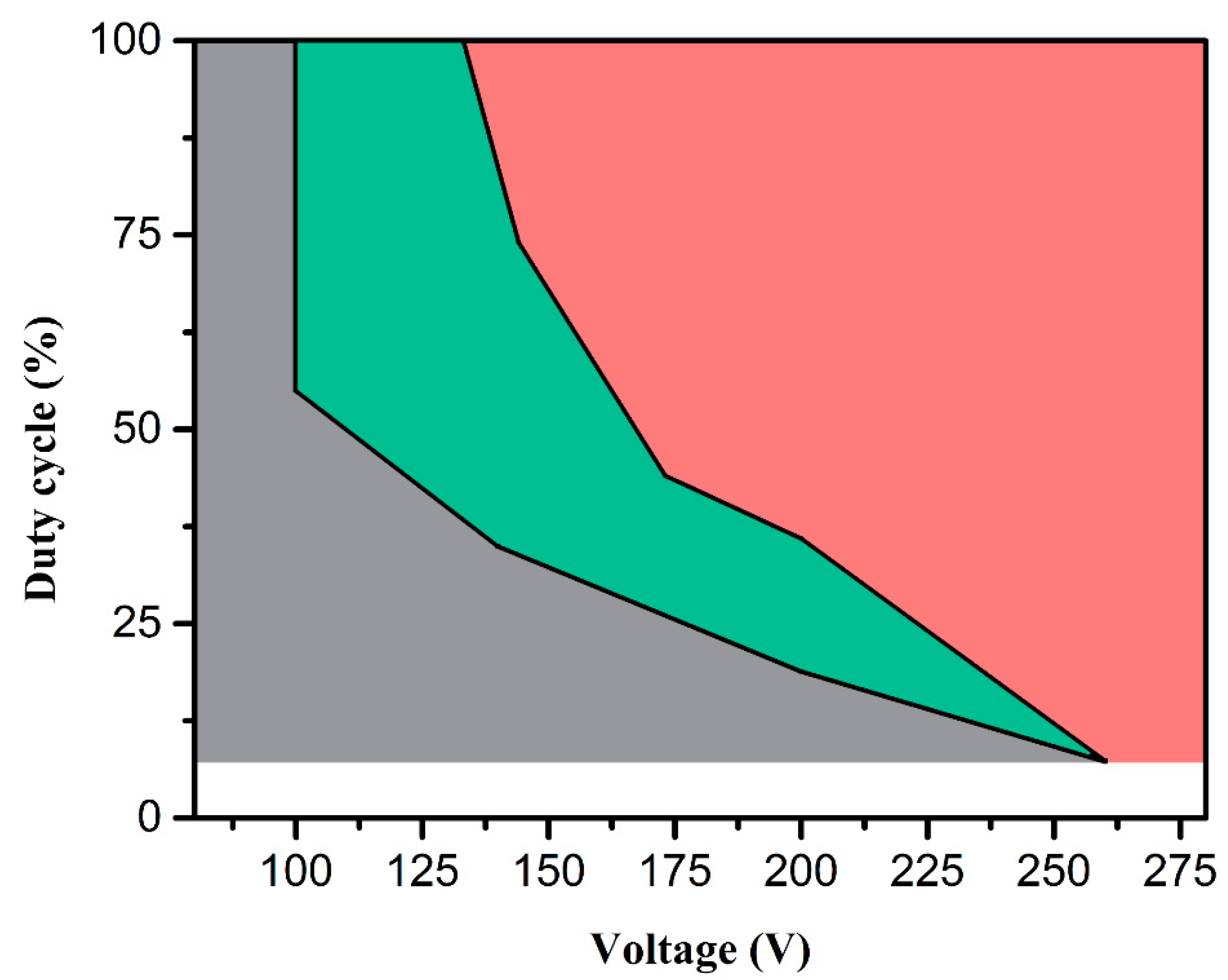
Figure 3.
Field emission scanning electron microscopy (FESEM) image of Q195 carbon structural steel surface: (a) Before electrolytic plasma processing (EPP); (b–f) With EPP treatment for 20 s, 30 s, 40 s, 60 s, and 80 s.
Figure 3.
Field emission scanning electron microscopy (FESEM) image of Q195 carbon structural steel surface: (a) Before electrolytic plasma processing (EPP); (b–f) With EPP treatment for 20 s, 30 s, 40 s, 60 s, and 80 s.

Figure 4.
X-ray diffraction (XRD) pattern of Q195 carbon structural steel: Before EPP (black curve); After EPP treatment for 25 s (red curve).
Figure 4.
X-ray diffraction (XRD) pattern of Q195 carbon structural steel: Before EPP (black curve); After EPP treatment for 25 s (red curve).
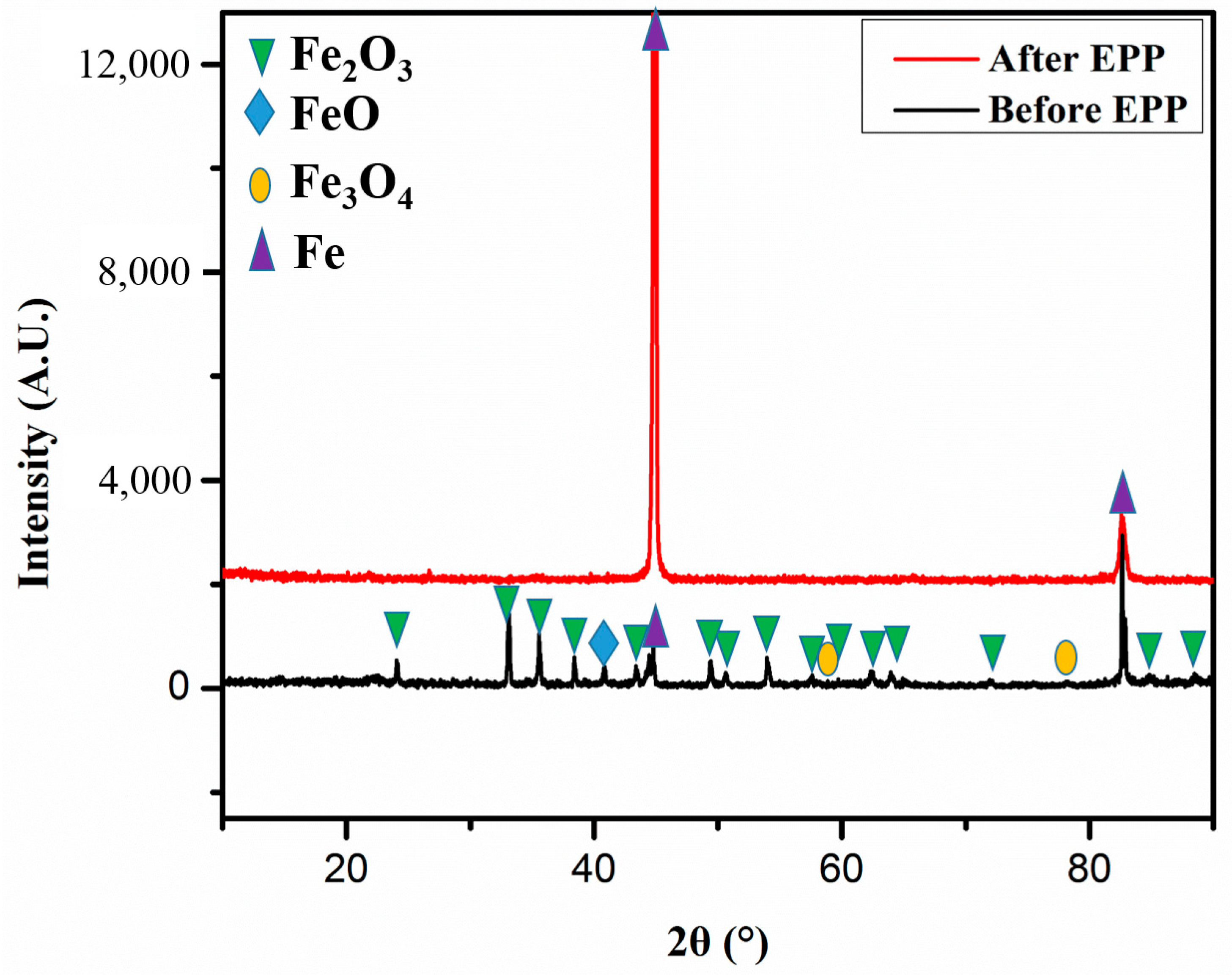
Figure 5.
Scanning electron microscopy (SEM) image of tensile fracture morphology of Q195 carbon structural steel. (a–c) Before EPP; (d–f) With 25 s EPP treatment.
Figure 5.
Scanning electron microscopy (SEM) image of tensile fracture morphology of Q195 carbon structural steel. (a–c) Before EPP; (d–f) With 25 s EPP treatment.

Figure 6.
Stress-strain curve of Q195 carbon structural steel. (Before EPP: black curve; After 25 s EPP treatment: red curve).
Figure 6.
Stress-strain curve of Q195 carbon structural steel. (Before EPP: black curve; After 25 s EPP treatment: red curve).
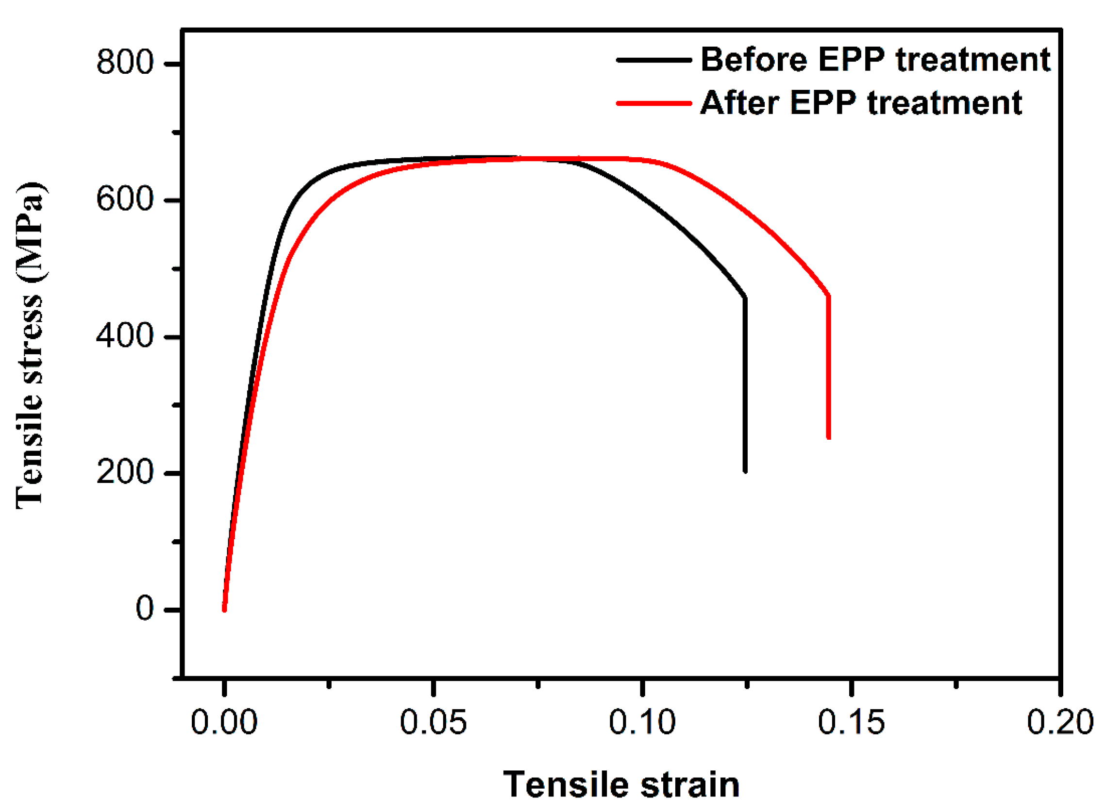
Figure 7.
(a) Elastic modulus histogram of Q195 carbon structural steel (b) Hardness histogram of Q195 carbon structural steel. (Before EPP: black curve; after 40 s EPP treatment: purple curve).
Figure 7.
(a) Elastic modulus histogram of Q195 carbon structural steel (b) Hardness histogram of Q195 carbon structural steel. (Before EPP: black curve; after 40 s EPP treatment: purple curve).
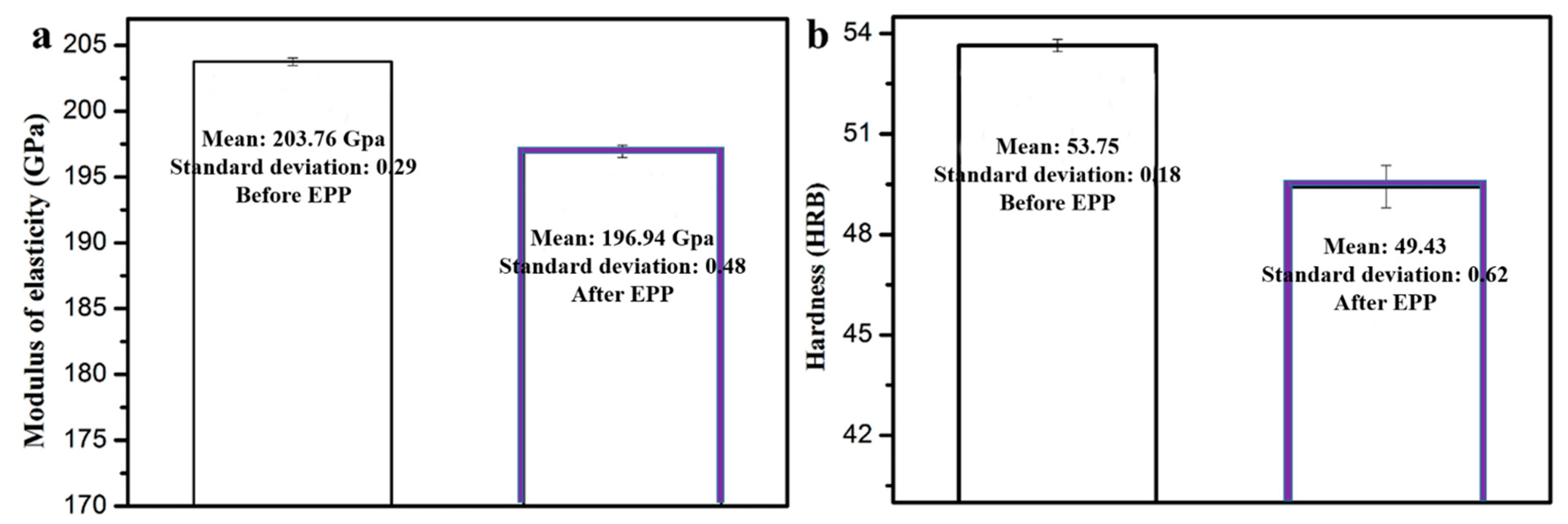
Figure 8.
XRD patterns of Q195 structure carbon steel: With 40 s EPP treatment (black line); After Zinc coating (red line).
Figure 8.
XRD patterns of Q195 structure carbon steel: With 40 s EPP treatment (black line); After Zinc coating (red line).

Figure 9.
Zinc coating under different voltages, surface morphology: (a) 150 V, (c) 180 V; Cross-section topography: (b) 150 V, (d) 180 V.
Figure 9.
Zinc coating under different voltages, surface morphology: (a) 150 V, (c) 180 V; Cross-section topography: (b) 150 V, (d) 180 V.


Table 1.
The mean elastic modulus and hardness of Q195 carbon structural steel before EPP and after EPP treatment for 40 s.
Table 1.
The mean elastic modulus and hardness of Q195 carbon structural steel before EPP and after EPP treatment for 40 s.
| Sample | EPP Treatment | Elastic Modulus/GPa | Hardness/GPa |
|---|---|---|---|
| Q195 carbon structural steel | 0 s | 203.76 | 53.75 |
| Q195 carbon structural steel | 40 s | 196.94 | 49.43 |
Table 2.
Composition of zinc coatings shown in Figure 8.
Table 2.
Composition of zinc coatings shown in Figure 8.
| Sample | Zn (at. %) | Fe (at. %) | C (at. %) | Si (at. %) | O (at. %) |
|---|---|---|---|---|---|
| a | 68.42 | 26.97 | 0.51 | 0.05 | 4.05 |
| b | 96.93 | 1.23 | 0.00 | 0.00 | 1.84 |
© 2018 by the authors. Licensee MDPI, Basel, Switzerland. This article is an open access article distributed under the terms and conditions of the Creative Commons Attribution (CC BY) license (http://creativecommons.org/licenses/by/4.0/).
Share and Cite
MDPI and ACS Style
Cheng, F.; Gui, W.; Lin, J. Surface Modification of Q195 Structure Carbon Steel by Electrolytic Plasma Processing. Metals 2018, 8, 831. https://doi.org/10.3390/met8100831
AMA Style
Cheng F, Gui W, Lin J. Surface Modification of Q195 Structure Carbon Steel by Electrolytic Plasma Processing. Metals. 2018; 8(10):831. https://doi.org/10.3390/met8100831
Chicago/Turabian StyleCheng, Fang, Wanyuan Gui, and Junpin Lin. 2018. "Surface Modification of Q195 Structure Carbon Steel by Electrolytic Plasma Processing" Metals 8, no. 10: 831. https://doi.org/10.3390/met8100831
Note that from the first issue of 2016, this journal uses article numbers instead of page numbers. See further details here.