Abstract
Using nanoindentation under various strain rates, the mechanical properties of a laser powder bed fusion (PBF) SKD61 at the 800 mm/s scan speed were investigated and compared to PBF H13. No obvious pile-up due to the ratio of the residual depth (hf) and the maximum depth (hmax) being lower than 0.7 and no cracking were observed on any of the indenter surfaces. The nanoindentation strain-rate sensitivity (m) of PBF SKD61 was found to be 0.034, with hardness increasing from 8.65 GPa to 9.93 GPa as the strain rate increased between 0.002 s−1 and 0.1 s−1. At the same scan speed, the m value of PBF H13 (m = 0.028) was lower than that of PBF SKD61, indicating that the mechanical behavior of PBF SKD61 was more critically affected by the strain rate compared to PBF H13. PBF processing for SKD61 therefore shows higher potential for advanced tool design than for H13.
1. Introduction
SKD61 and H13 are types of hot work tool steels applied to casting molds, extrusion tools, forging dies, etc., and the hardness of SKD61 (229 BHN) is lower than that of H13 (235 BHN) [1]. Both steels are fabricated by conventional methods requiring expensive dedicated tools, and thus are inappropriate for small-scale or complex-shape productions [2,3,4]. Selective laser melting (SLM), is a laser powder-bed additive manufacturing process that is suitable for the processing of tool steels, including SKD61 and H13, because it offers the ability to not only reduce the amount of machining and hence wastage of this expensive material, but also to produce intricate molds with a nearly full density and a refined microstructure [3,4].
The mechanical behavior of hot work tool steels prepared by the PBF method is one of the most important characteristics [5,6]. It was reported that the hardness of PBF SKD61 fabricated from commercial powders was higher than that made from gas atomized spherical powders [4,7]. Very recently, a few studies have addressed the mechanical properties of tool steel processed by PBF using nanoindentation [3,8]. For example, the H13 PBF-processed at 200 mm/s scan speed exhibited the lowest creep resistance and highest hardness values. However, very few studies have dealt with the mechanical behavior of PBF SKD61 using nanoindentation. It is thus necessary to perform nanoindentation tests to probe the creep behavior of the PBF SKD61 and compare it with that of PBF H13 [9,10].
In a previous study, PBF processing at an 800 mm/s laser scan speed was applied successfully for SKD61 powders [4,11]. This study expands on those reported findings by using nanoindentation tests to investigate the mechanical properties of PBF SKD61. Results for PBF-processed H13 at the same laser scan speed sourced from the literature are used in the evaluation conducted here [2].
2. Experimental Procedure
The material used in this work was SKD61 powder prepared by a gas atomizing process (Hot Gas Atomization System, HEMMIGA 100/25, PSI Ltd., Leicester, UK), as shown in Figure 1. Specifically, SKD61 ingot obtained from SeAH Special Steel Corp. (Changwon, Korea) was melted into a graphite crucible at 1690 °C under a high purity argon atmosphere. The alloy liquid was then ejected through a spray nozzle under hot N2 gas pressure of 50 bar. Upon gas atomization, the gas-atomized powders were collected and loaded onto a series of ASTM E11 standard sieves to obtain a specific particle size range of 10~45 μm. The elemental chemical compositions of the produced powders were confirmed by inductively coupled plasma (ICP, Spectro Arcos ICP-AES, Kleve, Germany). The powders were then processed by a PBF device (a Concept Laser Mlab-Cusing System, Lichtenfels, Germany) equipped with a 90 W Nd:YAG fiber laser to manufacture cuboid specimens (10 mm × 10 mm × 10 mm). Detailed preparation of the PBF samples was described in [3,4].
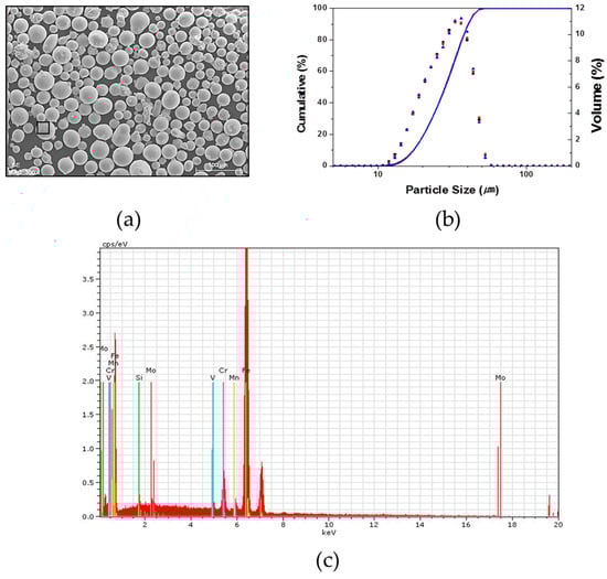
Figure 1.
(a) SEM picture of the powder input; (b) particle size distribution; and (c) EDS result at the location indicated by the rectangle in (a).
The cuboid specimens prepared by PBF were mounted in epoxy resin, cross-sectioned, and then mechanically polished on an auto-disc polishing machine (Struers LaboForce-100, Ballerup, Denmark) to reach mirror-like surfaces. The specimens with a surface roughness of lower than 50 nm determined using a SV-3200S4 (Mitutoyo, Sakado, Japan) were used for the next steps. An optical microscope (OM, Nikon ECLIPSE MA200, Nikon, Tokyo, Japan) and a scanning electron microscope (SEM, JSM-5800, JEOL, Tokyo, Japan) were also used to observe the microstructure on the sample surfaces. Nanoindentation tests were then performed for those samples at room temperature at the same maximum load (500 mN) on a NanoTest nanoindenter (Micro Materials Ltd., Wrexham, UK) using a three-sided Berkovich diamond indenter. Specifically, all nanoindentation tests were carried out at loading rates of 50 mN/s, 25 mN/s, 16.67 mN/s, 12.5 mN/s, 10 mN/s, 5 mN/s, and 1 mN/s. The indenter was then held at the maximum load for 5 s, which was followed by unloading at a rate of 50 mN/s for all tests. At least 10 indentation points at each loading rate were carried out and the results were averaged.
3. Results and Discussion
Figure 2a shows the OM and SEM microstructure result of the SKD61 sample prepared by PBF at the 800 mm/s scanning speed, in which the inset is the SEM result. In the OM image, the melt pool confirmed the scan direction and some pores. Figure 2b shows a SEM result at the location of an indenter point. Figure 2a reveals some black pores with irregular shapes and small volumes observed over the sample. The volume fraction of the black phase was calculated, using the image analysis software, to be 1.4%, which is lower than that (5.2%) for PBF H13 at the same scan speed [3]. Black pores, indicating imperfections in the microstructure, may stem from insufficient laser energy to melt powder materials within the melt pool, causing a short cooling (faster solidification) time and insufficient melting of the substrate and powders [3].
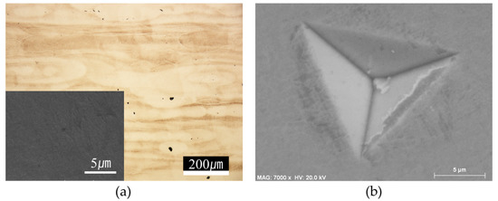
Figure 2.
(a) Microstructure of the PBF- processed SKD61 at 800 mm/s scanning speed; (b) SEM graph of an indenter point after nanoindentation tests.
The widely used Oliver and Pharr method is accurate only for nanoindents that do not show significant pile-up deformation, which is related to the ratio of the residual depth (hf) and the maximum depth (hmax) [12,13,14]. In the SEM results of indenter points on all sample surfaces, no obvious pile-up was observed, as shown in Figure 2b. This result is similar to that of the PBF H13 material, where it was confirmed that in all nanoindentation tests was lower than 0.7 [3]. Therefore, the Oliver and Pharr method can be adopted to extract the hardness values of the material here. Moreover, no cracking in Figure 2b is observed, indicating that the material has low crack sensitivity.
In this study, a constant rate of loading (CRL) method, where a steady loading rate is used until the tip depth rate becomes nearly constant, was used to determine the strain rate () because the CRL allows for simple calculation of strain rates, and also is proven to be more suitable to correlate with the conventional constant strain rate tests [12,15,16]. In fact, both indentation hardness and strain rate are not constant under CRL loading, causing difficulty in determining a consistent creep exponent from a single CRL nanoindentation experiment [9,10,17,18]. However, if only the indentation hardness and indentation strain rate at the maximum load point are used, the strain-rate sensitivity can be determined from a group of CRL nanoindentation tests under different loading rates [15]. Accordingly, the above loading rates corresponded to strain rates of 0.1 s−1, 0.05 s−1, 0.033 s−1, 0.025 s−1, 0.02 s−1, 0.01 s−1, and 0.002 s−1, respectively.
Figure 3 is plotted to compare the hardness of SKD61 and H13 processed by PBF at an 800 mm/s scan speed. Error bars on the data reflect the standard deviation calculated for the hardness from multiple indentations for each sample. Experimental results from nanoindentation tests of H13 prepared by PBF at 800 mm/s, obtained from another report in the literature, are included for comparison [3]. As shown in Table 1, the hardness increases in ranges of (8.65–9.99) GPa and (7.91–8.84) GPa for the SKD61 and H13 materials, respectively, prepared by PBF at the same scan speed of 800 mm/s at nanoindentation strain rates in the range of 0.002 s−1 and 0.1 s−1. This shows the PBF SKD61 has about 10% higher hardness values on average than the PBF H13 material.
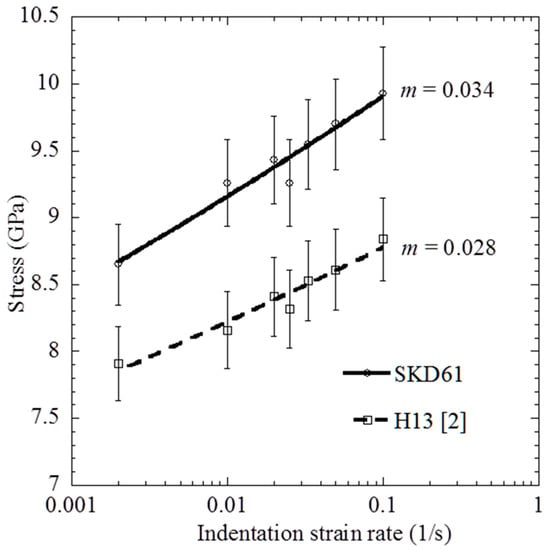
Figure 3.
Indentation stress as a function of the strain rate for PBF processed by SKD61 and H13.

Table 1.
Hardness values of SKD61 and H13 prepared by the PBF process at the same scan speed of 800 mm/s.
By assuming the indentation strain rate and hardness are proportional to the flow strain rate and stress, respectively, it follows that the strain rate sensitivity (SRS) can be defined as:
The slope of the straight line in Figure 3 represents the strain-rate sensitivity exponent (m), with a value of 0.034 and 0.028 for the PBF SKD61 and H13, respectively. The strain-rate sensitivity of PBF SKD61 was higher than that of PBF H13, indicating that the mechanical behavior of H13 material is less susceptible to the strain rate than SKD61.
In recent studies, the optimal laser scan speed for the PBF process was around 200 mm/s for H13 [3], and the hardness increased from 8.61 GPa to 9.29 GPa; these values are lower than those of SKD61 in the present study at the same strain rate range. The laser energy density (E) can be defined as:
where P is the laser power (W), v is the scan speed (mm/s), h is the hatch distance (μm), and t is the layer thickness (μm). The laser energy density was calculated by Equation (2), and it was 156.2 kW·h/m3. Because the laser energy density is inversely proportional to the scan speed [19,20,21,22], the optimal condition of the PBF process for SKD61 consumes less energy than for H13. In the case of the same process conditions, PBF SKD61 showed less pores then PBF H13 in the SEM images. It is not shown in this manuscript because the results of PBF SKD61 and H13 are included in various process conditions. We considered optimal process conditions and then the indentation stress of two specimens, in which PBF SKD61 and H13 were compared. Moreover, PBF SKD61 showed a better microstructure (less pores) and higher hardness than PBF H13. Therefore, PBF SKD61 shows higher potential for advanced tool design than PBF H13.
4. Conclusions
This study demonstrates successful printing of SKD61 by the PBF method at an 800 mm/s laser speed. From the results, no obvious pile-up (due to < 0.7) and no cracking on all indenter surfaces were observed. Hardness increased from 8.65 GPa to 9.93 GPa as the strain rate increased in a range of 0.002 s−1 and 0.1 s−1. At the same scan laser speed, the m value of PBF SKD61 (m = 0.034) was higher than that of PBF H13 (m = 0.028), indicating that the mechanical behavior of the PBF SKD61 was more critical to the strain rate compared to PBF H13. As a result, PBF processing for SKD61 shows higher potential in practical application than for H13 due to the superior microstructure and mechanical behavior of the former, and less laser energy consumption at the optimal condition.
Author Contributions
writing-original draft preparation, J.Y.; conceived and designed the experiments, V.L.N. and J.Y.; performed the experiments, J.C.; analyzed the date, D.-Y.Y., H.-S.L. and S.Y.; edited the paper, J.-H.Y.
Acknowledgments
This study was supported by the Fundamental Research Program of the Korea Institute of Materials Science (Development of High Performance Materials and Processes for Metal 3D Printing).
Conflicts of Interest
The authors declare no conflict of interest.
References
- Astmsteel, Hot Work Steel Comparison: H13 vs 1.2344 vs SKD61. Available online: http://www.astmsteel.com/steel-knowledge/hot-work-steel-h13-1-2344-skd61/ (accessed on 27 November 2018).
- Sander, J.; Hufenbach, J.; Giebeler, L.; Wendrock, H.; Kuhn, U.; Eckert, J. Microstructure and properties of FeCrMoVC tool steel produced by selective laser melting. Mater. Des. 2016, 89, 335–341. [Google Scholar] [CrossRef]
- Nguyen, V.L.; Kim, E.A.; Lee, S.R.; Yun, J.C.; Choe, J.H.; Yang, D.Y.; Lee, H.S.; Lee, C.W.; Yu, J.H. Evaluation of strain-rate sensitivity of selective laser melted H13 tool steel using nanoindentation tests. Metals 2018, 8, 589. [Google Scholar] [CrossRef]
- Yu, J.H.; Yang, D.Y.; Lee, H.S.; Kim, S.W.; Yang, S.S.; Lim, T.S.; Lee, C.W. Characteristics of SLM printed SKD61 alloy by using of gas atomized spherical powders. KSME Spring Conf. 2016, 1143–1144. [Google Scholar]
- Dirk, H.; Vanessa, S.; Eric, W.; Claus, E. Additive manufacturing of metals. Acta Mater. 2016, 117, 1–22. [Google Scholar]
- Gu, D.D.; Meiners, W.; Wissenbach, W.; Proprawe, R. Laser additive manufacturing of metallic components: Materials, processes and mechanisms. Int. Mater. Rev. 2012, 57, 133–164. [Google Scholar] [CrossRef]
- Geldart, D.; Abdullah, E.C.; Hassnapour, A.; Nwoke, L.C.; Wouters, I. Characterization of powder flowability using measurement of angle of repose. China Particuol. 2006, 4, 104–107. [Google Scholar] [CrossRef]
- Duan, Z.; Pei, W.; Gong, X.; Chen, H. Superplasticity of annealed H13 steel. Materials 2017, 10, 870. [Google Scholar] [CrossRef] [PubMed]
- Attar, H.; Ehtemam-Haghighi, S.; Kent, D.; Dargusch, M.S. Recent developments and opportunities in additive manufacturing of titanium-based matrix composited: A review. Int. J. Mach. Tool Manu. 2018, 85–102. [Google Scholar] [CrossRef]
- Attar, H.; Ehtemam-Haghighi, S.; Kent, D.; Okulov, I.V.; Wendrock, H.; Bönisch, M.; Volegov, A.S.; Calin, M.; Eckert, J.; Dargusch, M.S. Nanoindentation and wear properties of Ti and Ti-TiB composite materials produced by selective laser melting. Mater. Sci. Eng. A 2017, 20–26. [Google Scholar] [CrossRef]
- Yun, J.; Choe, J.; Lee, H.; Kim, K.-B.; Yang, S.; Yang, D.-Y.; Kim, Y.-J.; Lee, C.-W.; Yu, J.-H. Mechanical Property Improvement of the H13 Tool Steel Sculptures built by Metal 3D Printing Process via Optimum Conditions. J. Korean Powder Metall. Inst. 2017, 24, 195–201. [Google Scholar] [CrossRef]
- Oliver, W.C.; Pharr, G.M. An improved technique for determining hardness and elastic modulus using load and displacement sensing indentation experiments. J. Mater. Res. 1992, 7, 1564–1583. [Google Scholar] [CrossRef]
- Gu, S.T.; Chai, G.Z.; Wu, H.P.; Bao, Y.M. Characterization of local mechanical properties of laser-cladding H13-TiC composite coatings using nanoindentation and finite element analysis. Mater. Des. 2012, 39, 72–80. [Google Scholar] [CrossRef]
- Yadroitsev, I.; Bertrand, P.; Smurov, I. Parametric analysis of the selective laser melting process. Appl. Surf. Sci. 2007, 253, 8064–8069. [Google Scholar] [CrossRef]
- Du, Y.; Liu, X.H.; Fu, B.; Shaw, T.M.; Lu, M.; Wassick, T.A.; Bonilla, G.; Lu, H. Creep characterization of solder bumps using nanoindentation. Mech. Time-Depend Mater. 2017, 21, 287–305. [Google Scholar] [CrossRef]
- Peykov, D.; Martin, E.; Chromik, R.R.; Gauvin, R.; Trudeau, M. Evaluation of strain rate sensitivity by constant load nanoindentation. J. Mater. Sci. 2012, 47, 7189–7200. [Google Scholar] [CrossRef]
- Hu, J.J.; Zhang, Y.S.; Sun, W.M.; Zhang, T.H. Nanoindentation-induced pile-up in the residual impression of crystalline Cu with different grain size. Crystals 2018, 8, 9. [Google Scholar] [CrossRef]
- Liu, C.Z.; Chen, J. Nanoindentation of lead-free solders in microelectronic packaging. Mater. Sci. Eng. A 2007, 448, 340–344. [Google Scholar] [CrossRef]
- Simchi, A. Direct laser sintering of metal powders: Mechanism, kinetics and microstructural features. Mater. Sci. Eng. A 2006, 428, 148–158. [Google Scholar] [CrossRef]
- Carter, L.N.; Wang, X.; Read, N.; Khan, R.; Aristizabal, M.; Essa, K.; Attallah, M.M. Process Optimisation of Selective Laser Melting using Energy Density Model for Nickel-based Superalloys. Matter. Sci. Technol. 2016, 32, 657–662. [Google Scholar] [CrossRef]
- Körner, C. Additive manufacturing of metallic components by selective electron beam melting—A review. Int. Mater. Rev. 2016, 61, 361–377. [Google Scholar] [CrossRef]
- Kasperovich, G.; Haubrich, J.; Gussone, J.; Requena, G. Correlation between porosity and processing parameters in TiAl6V4 produced by selective laser melting. Mater. Des. 2016, 105, 160–170. [Google Scholar] [CrossRef]
© 2018 by the authors. Licensee MDPI, Basel, Switzerland. This article is an open access article distributed under the terms and conditions of the Creative Commons Attribution (CC BY) license (http://creativecommons.org/licenses/by/4.0/).