Effect of Sub-Zero Treatment Temperatures on Hardness, Flexural Strength, and Fracture Toughness of Vanadis 6 Ledeburitic Die Steel


1
Faculty of Material Sciences and Technology of the STU in Trnava, J. Bottu 25, 917 24 Trnava, Slovakia
2
Institute of Physics of Materials, CEITEC-IPM, Czech Academy of Sciences, Zizkova 22, 616 62 Brno, Czech Republic
3
Prikner—Heat Treatment of Metals, Martínkovice 279, 550 01 Martínkovice, Czech Republic
4
Department of Metal Processing, AIR PRODUCTS spol. s r.o., Ústecká 30, 405 02 Děčín, Czech Republic
*
Author to whom correspondence should be addressed.
Metals 2018, 8(12), 1047; https://doi.org/10.3390/met8121047
Submission received: 7 November 2018
/
Revised: 7 December 2018
/
Accepted: 8 December 2018
/
Published: 11 December 2018
(This article belongs to the Special Issue Tool Steels)
Abstract
:Any improvement on the service life of tools reduces the tooling costs, and assists to increase labor productivity by decreasing the needs for either the tools’ re-grinding or their replacement. This requires, among others, an enhancement of the key mechanical properties of the tool materials, by newer treatment route development. The current paper describes the impact of different heat treatment regimes, including austenitizing; sub-zero treatments; and tempering on the hardness, flexural strength, and toughness of tool steel, which is demonstrated upon Vanadis 6 steel. An improvement in the hardness due to the sub-zero treatment is reported, but it is also pointed out that both the flexural strength and fracture toughness of the material cannot be inevitably deteriorated by the application of this processing. Finally, it is demonstrated that both of these properties, despite their conflicting relationship, in most cases, can be improved simultaneously when the material is treated in the proper way.
1. Introduction
High-chromium high-vanadium ledeburitic cold work die steels have been extensively used in industrial applications where high hardness and nondeforming qualities are required. In addition, alloying with vanadium provides the materials with an outstanding wear resistance. To obtain these beneficial characteristics, the steels must be subjected to a proper heat treatment procedure, which is specific to each steel grade. This comprises austenitizing, which is followed by rapid quenching to the room temperature (also called as “conventional heat treatment” (CHT)). As-quenched ledeburitic steels contain martensite; retained austenite (10–20 vol. %); and undissolved carbides of a different chemistry, crystallography, size, and shape. The subsequent tempering induces the precipitation of carbides, converts the retained austenite into either martensite or bainite (in the case of high temperature tempering), and thereby determines the final bulk microstructure and properties of a particular steel.
It has been demonstrated that the application of the sub-zero treatment (SZT) further extracts the durability of the tools [1,2,3,4]. These improvements are based on the significant reduction of the retained austenite [5,6,7,8,9,10,11,12], accelerated precipitation rate and more uniform transient precipitates distribution [13,14], martensite refinement [11,12], and substantially enhanced number and population density of small globular carbides [5,6,7,8,9,10,11,14,15,16,17,18].
The mentioned variations in the microstructure provide the steels with a better wear resistance and high resistivity to undesirable dimensional changes, which is the prerequisite for the enhancement of the service life time of tools and components. On the other hand, the resistance against crack initiation/propagation (being quantified by impact toughness, flexural strength, and/or fracture toughness) is generally lowered by the presence of carbides, as they are brittle in nature. Moreover, the materials manufactured by “classical” ingot metallurgy suffer from the anisotropy of carbide particle distribution, as well as from carbide stringers and clusters, which often act as the nuclei of premature fracture of tools. Despite the fact that it is important to keep at least an acceptable level of the steel toughness, little attention has been paid to date to its experimental determination for ledeburitic steels. Moreover, the obtained results manifest an evident inconsistency. For instance, Surberg et al. [19] and Molinari et al. [20] reported almost no effect of SZT on impact toughness, while Collins and Dormer [16] and Rhyim et al. [21] recorded a considerable reduction of impact toughness using the application of SZT for the treatment of the same steel grade. Also, the obtained results on the fracture toughness, KIC, are mostly inconsistent. Das et al. [17], for instance, reported on the deterioration of the fracture toughness because of SZT, but this deterioration was most pronounced after SZTs at −75 and −125 °C, while the SZT at −196 °C led only to a minimal KIC reduction. In our recent papers [15,22,23], on the other hand, almost no effect, or rather fracture toughness, has been reported for the improvement of Vanadis 6 steel when SZT is at −196 and −140 °C. Also, it has been demonstrated that the flexural strength is slightly (and rather positively) affected by this treatment.
The question of the optimal SZT temperature and duration at this temperature is still under debate. In the 1950s, it was believed that temperatures down to approximately −75 °C were sufficient to transform a substantial portion of the retained austenite into the martensite, and that lower temperatures had no practical effect in the treatment of steels. Much later, a boiling temperature of liquid nitrogen (−196 °C) was suggested for treatment, and most of the experimental works have been conducted using this temperature. Alternatively, only few studies suggested other temperatures, for instance −140 °C, for the treatment of Cr-ledeburitic tool steels [2,24]. Stratton [1], on the other hand, recommended using a boiling helium temperature (−269 °C) for treatment in selected cases.
The current paper summarizes the findings of the investigations that are focused on the impact of different SZT conditions (temperature and processing time) on the mechanical performance of Cr-V ledeburitic cold work die steel Vanadis 6. Contrary to our previous papers in this field, here, we firstly focused our interest on the phenomena that are affected by different SZT temperatures, including their crucial impact on the mechanical properties.
2. Material and Experimental Methods
2.1. Material and Processing
The experimental material was powder metallurgy (PM) ledeburitic tool steel Vanadis 6, with a nominal composition (in wt %) of 2.1% C, 1.0% Si, 0.4% Mn, 6.8% Cr, 1.5% Mo, 5.4% V, and Fe as the balance. The steel was supplied as soft-annealed flat bars, with a hardness of 270 HV10. The choice of the PM Cr-V ledeburitic steel was motivated by the fact that it manifests a high degree of microstructure isotropy, which enables us to disregard the orientation in the sampling [25].
The samples were net-shape machined and were subjected to pre-determined heat treatment schedules (Figure 1). Conventional heat treatment (CHT) consisted of the following steps: Gradual heating up to the desired austenitizing temperature TA (1050 °C) in a vacuum furnace (1), holding at that temperature for 30 min to homogenize the austenite (2), followed by quenching by nitrogen gas (five bar) (3). One set of specimens was tempered after quenching, without SZT. Another three sets of specimens were, immediately after quenching to room temperature, moved to the cryogenic system, where they were cooled down at a cooling rate of 1 °C/min to the SZT temperature (4). The SZTs have been carried out at three different temperatures, namely −140, −196, and −269 °C, and for a duration of 17 h (5). After that, the material was re-heated to the room temperature, using a heating rate of 1 °C/min (6). Double tempering (2 + 2 h) was performed immediately ((7) and (8)), namely at temperatures of 170 or 530 °C. In addition, the tempering temperatures of 330 and 450 °C were used for the construction of the tempering charts.
The SZT temperatures were generated as follows: For treatment at −140 °C, cold nitrogen gas was introduced into the cryogenic system. The treatment at −196 °C was carried out in liquid nitrogen; however, first, only cold nitrogen gas was supplied into the processing chamber, and only after the specimens were cooled down to approximately −190 °C did the liquid nitrogen come into touch with the steel specimens. The temperature of −269 °C was generated by liquid helium. Also, in this case, the samples were cooled down to the temperature of the liquid nitrogen, by introducing cold nitrogen gas into the cryogenic system, and were held there for 15 min, in order to equalize the temperature through the specimens. Afterwards, the specimens were moved into a Dewar’s container filled with liquid helium, cooled down to the temperature of −269 °C, and held there for 17 h.
2.2. Experimental Methods
The flexural strength was measured on bar test specimens with dimensions of 10 mm × 10 mm × 100 mm, and with a defined final surface roughness of Ra = 0.05–0.07 μm. It should be noted that it is very important to define the surface roughness before testing, as it was initially demonstrated that the flexural strength, as a measure of the resistance of the material against the fracture initiation, is strongly dependent on the Ra parameter [26]. The specimens were loaded in three-point bending at a loading rate of 1 mm/min, up to the moment of fracture. The distance between the loading roller supports was 80 mm. The flexural strength was determined from the maximum (fracture) load according to standard approach. In addition, the work of fracture, Wof, was determined as the deformation energy evaluated from the corresponding area below the measured load–displacement curve.
For the fracture toughness determination, pre-cracked specimens with dimensions of 10 mm × 10 mm × 55 mm were used. Both the pre-crack preparation and the tests were carried out at room temperature according to the ISO 12135 standard [27]. For the test, an Instron 8862 machine was used; the samples were loaded in three-point bending, with a roller span of 40 mm, and a loading rate of 0.1 mm/min was applied. The specimen deflection was measured by means of an inductive transducer integrated directly into the loading axis. In total, five samples were tested for each investigated condition.
Macro-hardness measurements were completed using the Vickers (HV10) method. Ten measurements were made for the metallographic specimens processed with any heat-treatment parameters, and both the mean values and standard deviations were then calculated.
The material microstructure was evaluated using optical and scanning electron microscopy. The morphology of the broken test specimens was examined using a JEOL JSM 7600F scanning electron microscope (SEM, Jeol Ltd., Tokyo, Japan). The analysis was coupled with energy dispersive spectrometry (EDS, Oxford Instruments, plc., High Wycombe, UK), in order to make a clear distinction between the eutectic (ECs) and secondary carbides (SCs). For further details regarding the categorization of carbides, check the literature [11,28]. In brief, the ECs contain mainly vanadium (more than 50 mass%), and much lower amounts of chromium and iron. Alternatively, chromium and iron (at a ratio of around 1:1) are the most represented elements in SCs. Also, it has been established recently that the EC-particles are MC-carbides with the SCs, namely M7C3 [11,14,18]. The population densities of each carbide type have been determined on twenty-five randomly acquired SEM micrographs, at a magnification of 3000×. The mean values and the standard deviations of the obtained data were calculated.
X-ray diffraction (XRD) line profiles have been recorded using a Phillips PW 1710 diffractometer (Philips Analytical B.V., Almelo, The Netherlands), by filtered Coα1,2 characteristic radiation. A range of two-theta angles of 30–127° was considered for the recording of the diffraction peaks. The retained austenite content, γR, was determined in accordance with the appropriate ASTM standard [29]. Here, it should be noted that the characteristic peaks of the major solid solutions, which are considered for the determination of the γR amounts, are often superimposed by peaks of the carbides. Therefore, the analysis was coupled with the Rietveld refinement of the obtained X-ray spectra, before computing the γR content.
3. Results and Discussion
Figure 2a is an optical micrograph of the initial (as-received) state of the experimental steel. The microstructure is composed of matrix and fine carbides, which are uniformly distributed throughout the matrix. The SEM micrograph (Figure 2b) and corresponding EDS maps of chromium and vanadium (Figure 2c,d) provide better insight into the as-annealed microstructure of the Vanadis 6 steel. It is shown that three modifications of carbides are presented in the steel. The first type of particle is presented as fine globular carbides in the ferritic matrix, and is denoted as spheroidized pearlite (SP). Also, secondary and eutectic carbides (SCs and ECs) appear in the steel microstructure. EDS maps (Figure 2c,d) clearly delineate that the carbides involved in SP, as well as the coarser particles (size 1–3 μm), contain a high chromium amount, while the carbides with a size of around 1.5 μm are vanadium-rich. According to the recently published results [28,30], one can conclude that both the SCs and particles in SP are M7C3-carbides, while the vanadium-rich particles belong to the group of ECs, and they are of a MC nature.
Typical SEM micrographs showing the microstructure of CHT, and differently SZT specimens after low-temperature tempering, are presented in Figure 3. The steel contains the martensite, the retained austenite, eutectic carbides (ECs), secondary carbides (SCs), and small globular carbides after CHT (Figure 3a). The application of SZTs reduces the retained austenite amount and increases the number of SGCs, while the numbers of both the ECs and SCs are unaffected. The increase of the SGC numbers is the maximum for the specimen that was subjected to the SZT at −140 °C, while the other SZTs gave lower SGCs counts (Figure 3b–d).
The SEM micrographs of the microstructures after tempering at 530 °C are shown in Figure 4. This tempering temperature is high enough to evoke the retained austenite transformation, thus, all of the specimens were almost free of this phase. The CHT steel and the steel after different SZTs contained tempered martensite, ECs, SCs, and SGCs. The increased tempering temperature promotes a decrease in the SGC numbers, while the numbers of both the ECs and SCs are unaffected.
The results of the quantitative analysis of the SGCs are summarized in Figure 5, where it is obvious that treatment at −140 °C produces the highest population density of these particles, and that the enhanced population density of the SGCs (compared to the state after CHT) is retained after tempering.
Figure 6 shows the tempering diagram of the CHT steel as well as of the steel after different SZTs. It is visible that the SZTs improve the hardness over the conventional heat treatment. The hardness of the CHT material was 875 HV 10, and it was 933, 942, and 904 HV 10 for the specimens after SZT at −140, −196, and −269 °C, respectively.
Conventionally heat-treated steel manifests an evident hardness decrease within the low-temperature tempering range, but the material hardness remains almost constant within the high-temperature tempering range, at a level of 750 HV 10. The application of SZT increases the material hardness within the low-temperature tempering range, up to a temperature of 450 °C; the highest bulk hardness has been recorded for the steel processed in cold nitrogen gas, at −140 °C. Tempering within the secondary hardening temperature range, however, decreases the hardness significantly, and except for SZT at −140 °C, its values are somewhat lower than what is obtained by CHT.
For the demonstration of the flexural strength variations, low- (at 170 °C) and high-temperature tempered steel specimens (at 530 °C) were selected. The reason for this is that cold-work tool steel grades are commonly used in the state after tempering to either “primary hardness” (tempering at low temperatures) or “secondary hardness” (tempering at high temperatures, usually around 500 °C). The graphical interpretations of the properties are in Figure 7 (flexural strength) and in Figure 8 (work of fracture). The results obtained after tempering at 170 °C infer that the flexural strength is improved because of the application of SZTs at −140 and −269 °C, but it is deteriorated after SZT at −196 °C. The corresponding work of fracture values, Wof, follow the flexural strength values well; the higher the flexural strength, the more energy is required for specimen fracture. The results obtained after tempering at 530 °C indicate that the flexural strength is almost unaffected by SZTs at −140 and −196 °C. It is, however, improved slightly for SZT at the boiling temperature of liquid helium. Compared to the state after CHT, the obtained results of the work of fracture manifest only weak variations after SZT at −140 and −196 °C. Alternatively, the work of fracture is significantly higher for the material that was subjected to the SZT at −269 °C, which corresponds well to the flexural strength changes.
Figure 9a–d shows an overview of the typical fracture surfaces of the specimens that were tempered at 170 °C after CHT, and after SZT at different temperatures. The fracture surface of the CHT specimen is shown in the SEM micrograph in Figure 9a. It appears smooth and shiny, with very little surface roughness. This is typical for hard and brittle metallic materials, for instance, for high-carbon high chromium ledeburitic die steels with a very high hardness, ball bearing steels, and so on. The fracture surfaces of the specimens that were subjected to different SZTs manifest a clearly evident topography as they appear rougher (Figure 9b–d). By comparing the SEM fractographs with the obtained values of both the flexural strength and the work of fracture, it is evident that there is close relationship between these characteristics, except for the specimen that was subjected to SZT at −196 °C.
However, detailed SEM micrographs (Figure 10a–d) clearly delineate the differences in the fracture surface morphology of the differently heat-treated specimens. By comparing these micrographs, it can be seen that the fracture surface roughness decreases in turn for the SZT specimens at −140 °C, SZT specimens at −269 °C, SZT specimens at −196 °C, and CHT steel. The detailed micrographs reveal that the area fraction of the cleavage fracture propagation is much more pronounced in the specimens of SZT at −196 °C than what is seen for SZT at −140 and 269 °C. The fracture propagated mostly in the so-called “low-energy” ductile manner in samples after SZT at −140 and −269 °C, while the fracture surfaces of the CHT material and the steel after SZT at −196 °C manifest a clearly visible cleavage propagation micromechanism.
Detailed SEM micrographs of the specimens tempered at 530 °C (Figure 11a–d) assist to draw the conclusion that the fracture surfaces of CHT and, differently, SZT steel, do not manifest significant differences in terms of their topography. All of the surfaces contain a great number of micro-dimples and holes, which correspond to the extraction of small globular carbides (SGCs) from the fracture surface during the crack propagation. This phenomenon becomes more clearly evident in the SZT specimens, as they contain a much higher amount and population density of these particles [10,11,14,18]. Besides that, micro-voids are also formed at the other carbide/matrix interfaces, however, coarser particles more easily undergo cleavage failure rather than a decohesive fracture propagation manner. This is due to the fact that coarser carbides are mostly M7C3 (average size of 2.5 μm), while the finer ones are MC (average size of 1.6 μm) [14,22]. The size effect of carbides on the fracture propagation manner has been investigated extensively. It has been established that the larger size of M7C3 carbides makes them very prone to cracking [17,31,32,33,34,35]. Also, the crystallography of the carbides should be taken into consideration when assessing their role in fracture behavior. The MC carbides are cubic, while the M7C3 carbides are hexagonal. Casellas et al. [36] and Lin et al. [37], for instance, studied the fracture toughness of the typical carbides that occur in cold work tool steels. They determined the fracture toughness of the MC phase to be 3.7 ± 0.6 MPa·m1/2. For the M7C3-carbides, the fracture toughness varied over a wide range, from 0.5 to 4 MPa·m1/2, whereas the lowest values correspond to the orientation parallel of the carbide’s main axis; meanwhile, the higher data was acquired in the orientation perpendicular to the carbide’s axis. One can thus summarize that M7C3-carbides are more brittle than MC, despite their lower hardness (1800 HV vs. 2500–3000 HV for the MC).
The above-mentioned findings are in close correlation to the microstructural characteristics. It is shown in Figure 3, Figure 4 and Figure 5 that the application of SZT produces a considerably enhanced number and population density of small globular carbides (SGCs), and that this material state is largely retained after tempering. The steel also contains eutectic and secondary carbides after the applied heat treatment schedule. However, the population density of these particles is unaffected by quenching and/or quenching followed by SZT [11,14,18]. The higher number of carbides produces more matrix/carbide interfaces. During crack propagation, the rigid carbides cannot co-deform with the matrix. Consequently, they can either crack by cleavage, or assist to decohesion always followed by a ductile microvoid coalescence fracture micromechanism. The higher the matrix/carbide interfaces number, the higher is the probability to form microvoids at these interfaces.
Another issue is the retained austenite amount. In the current investigation, the maximum retained austenite amount was found in the CHT material, and it was significantly reduced due to the application of SZT (Figure 12). Hence, one can expect that the CHT material would manifest a better flexural strength than what is obtained by the SZTs. However, SZT produces much more carbide particles, and thereby much more matrix/carbide interfaces, which, on the contrary, may act in favor of the better flexural strength of the SZT material.
The refinement of the martensitic domains was first recorded for 12% Cr–4% V ledeburitic steel by Tyshchenko et al. [12]. A plausible explanation for this phenomenon was delineated later by Jurči et al. [11]. He suggested dividing the γ to α’ transformation into two components, namely the diffusion-less (athermal) component and a time-dependent isothermal component. This is active during the steel holding at a SZT temperature, and is always connected with the extensive plastic deformation of newly formed “virgin” martensite, with the capture of carbon atoms by gliding dislocations, and thereby with mass transfer. The mass transfer, albeit in a limited extent, is associated with controlling the martensitic plates growth. In addition, the martensitic domains grow freely within the primary austenite grains at the beginning of the transformation. Alternatively, the space for their growth is considerably limited during the isothermal hold at the cryo-temperature, as the much space is already filled by the martensite formed athermally. The overall refinement of the matrix microstructure is then a consequence of the above mentioned two phenomena.
The grain refinement has beneficial a effect on both the strength and toughness of the metallic materials. This mechanism is known as “grain boundary strengthening”, and can be expressed by the Hall-Petch equation [38], as follows:
where σo is a friction stress (it involves contributions from both the solutes and foreign particles); k is the Hall–Petch constant (specific for each material); and d is the grain size, which is usually represented by the average grain diameter. In the particular case of martensitic structures (non-polyhedral), the parameter of grain size d cannot be taken into the consideration. Instead, the characteristic dimension d represents the width of the martensitic domains.
One can thus summarize that the better flexural strength of SZT material is due to the combined effect of the overall microstructure refinement and the enhanced population density of the carbides, despite the fact that the hardness is higher and the retained austenite is significantly reduced.
In tempering within the common secondary hardening temperature range, the role of the retained austenite can be disregarded, as the steel is almost free of this phase [14,18,39]. Hence, the slightly improved or almost equal flexural strength of SZT steel (as compared with the state after CHT) can be attributed only to the higher population density of the SGCs, and to the martensite refinement. The presence of a higher population density of SGCs essentially contributes to the decohesive fracture propagation manner (see also the discussion to the state after low-temperature tempering). Alternatively, high-temperature tempering induces the extensive precipitation of nano-sized carbides [14,18]. These carbides are coherent with the matrix, and make it more brittle. Therefore, one can conclude that the final flexural strength of the steel is always a result of the competition between the precipitation strengthening mechanism of carbides, and the mechanisms affecting microplastic performance of the matrix (because of the enhanced number of SGCs and the overall structural refinement).
Figure 13 shows the variations of the fracture toughness of the low- and high-temperature tempered specimens that were CHT and SZT at different temperatures.
In CHT steel, the fracture toughness KIC is comparably higher after tempering at 170 °C than what was achieved after tempering at 530 °C. The SZTs at −140 and −269 °C influence the fracture toughness only marginally after low-temperature tempering, but improve it substantially after tempering in the common normal secondary hardening temperature range. In addition, there is a detrimental effect of SZT at −196 °C after low-temperature tempering, while a slightly positive effect for a high-temperature tempered state is observed.
The observed variations of the fracture toughness with an aggregate effect of SZT and tempering can be referred to by the following factors:
- -
- -
- The application of SZT produces a considerably higher amount and population density of cementite particles (of size 100–500 nm, small globular carbides (SGCs)), whereas the SZT at −140 °C acts more effectively in this way [11,14,15,18,40]. Tempering always reduces the amount of these carbides. Despite that, however, it remains much higher than what can be obtained by CHT (Figure 5). The crack propagates by a decohesive mechanism at the carbide/matrix interfaces [15,22], which is connected with micro-plastic deformation. The more carbides, the higher is the probability to form the microvoids at the interfaces, and the higher the deformation energy is that is needed for the fracture propagation.
- -
In the case of low-temperature tempering, the KIC values were almost the same for the specimens after CHT and after SZT at −140 °C; the differences in the γR amount are compensated by variations in the number and population density of SGCs. The SZT at −196 °C further reduces the γR amount, and produces lower amounts of SGCs—this is why a low KIC level has been recorded.
As above mentioned, the role of the γR can be disregarded in the case of tempering into the common secondary hardening temperature range. The resulting KIC level is then a function of the number and population density of SGCs; this is the highest one after SZT at −140 °C. Also, the variations in the extent of the carbides precipitation should be considered; SZT at −196 °C suppresses the precipitation of M7C3, which results in a lower matrix hardness, and thereby in a slightly higher KIC than what is obtained after CHT.
Finally, SZT at −140 °C lowers neither the flexural strength of the steel (Figure 7 and Figure 8) nor its fracture toughness (Figure 13) in the as-low-temperature tempered state, at a significantly enhanced hardness. In addition, this kind of treatment improves all of these mechanical properties after tempering within the common secondary hardening temperature range. It has been demonstrated recently [39] that SZTs at −196 °C do not act in favor of simultaneous improvement of hardness and toughness after low-temperature tempering, while these properties are slightly improved after high temperature tempering. Therefore, the treatment at −140 °C enhances the hardness along with the toughness to a much more remarkable extent, as compared to the state after conventional heat treatment. The treatment in liquid helium seems to also be a promising way how to improve the hardness and toughness simultaneously. The temperature of the treatment is very low, however, and practically there is limited transport of atoms possible at 4 K. Hence, all of the processes being responsible for the ameliorations of mechanical properties inevitably take a very long time, which is unacceptable from the point of view of the overall economy of the treatment, due to the high price of helium, among others.
4. Conclusions
The results obtained by the systematic investigations of the effect of the sub-zero treatments at different temperatures (−140, −196, and −269 °C), and the tempering on the hardness, fracture toughness, and flexural strength, allow for making the following main conclusions:
- (i)
- The hardness is generally improved by the SZTs applied; this improvement is the most pronounced for SZT at −140 °C, while other SZT conditions gave a less remarkable hardness increase. The observed improvement has been assigned to the increased volume fraction of small globular cementite carbides, because of the microstructural changes that occurred at subzero temperatures.
- (ii)
- The fracture toughness level is generally unaffected or somewhat worsened for the material after low-temperature tempering. In high-temperature tempered samples (in secondary hardening range), an improvement of the fracture toughness has been recorded. A higher number of small globular cementite particles increases the number of nucleation sites, by decohesion particles to the matrix interface boundary. On the other hand, the microstructure refinement contributes to the higher fracture resistance of the matrix. As a consequence, the potential for fracture toughness enhancement is not too high, but, under improvement of the hardness, there is no risk for a toughness decrease.
- (iii)
- The flexural strength is slightly improved by SZTs, except for the case of SZT in liquid nitrogen, where no effect or a slight worsening has been recorded. Although changes in the flexural strength with applied SZTs conditions are analogous to the hardness changes, there is another aspect going against the better improvement. These are associated with increased number of decohesion sites at the carbide-matrix interface. contributing to a low energy ductile fracture.
- (iv)
- The SZTs at −140 and −269 °C make it possible to obtain the simultaneous improvement of both the hardness and toughness in a much greater extent than the SZTs carried out at other treatment temperatures. However, the use of the boiling temperature of liquid helium may be associated with excessive production costs.
Author Contributions
Writing of manuscript, P.J. and I.D.; methods of research, P.J. and I.D.; realization of heat treatments, P.P. and Z.M.; microstructural investigations, P.J. and I.D.; investigations of mechanical properties, I.D.; project administration, P.J.; funding acquisition, P.J.
Funding
This research was funded by the Scientific Grant Agency of the Ministry of Education, Science, Research, and Sport of the Slovak Republic and the Slovak Academy of Sciences, under project no. 1/0264/17; the Scientific Grant Agency of the Ministry of Education, Science, Research, and Sport of the Slovak Republic and the Slovak Academy of Sciences.
Acknowledgments
The authors acknowledge that the paper is a result of the experiments realized within the project VEGA 1/0264/17. In addition, this publication is the result of the project implementation “Centre for Development and Application of Advanced Diagnostic Methods in Processing of Metallic and Non-Metallic Materials—APRODIMET”, ITMS: 26220120014, supported by the Research and Development Operational Programme funded by the ERDF.
Conflicts of Interest
The authors declare no conflict of interest.
References
- Stratton, P.F. Optimising nano-carbide precipitation in tool steels. Mater. Sci. Eng. 2007, A449–451, 809–812. [Google Scholar] [CrossRef]
- Reitz, W.; Pendray, J. Cryoprocessing of Materials: A Review of Current Status. Mater. Manuf. Proc. 2001, 16, 829–840. [Google Scholar] [CrossRef]
- Sweeney, T.P. Deep cryogenics: the great cold debate. J. Heat. Treat. 1986, 2, 28–33. [Google Scholar]
- Yugandhar, T.; Krishnan, P.K.; Bhaskar Rao, C.V.; Kalidas, R. Cryogenic Treatment and It’s Effect on Tool Steel. In Proceedings of the 6th International Tooling Conference, Karlstad, Sweden, 10–13 September 2002; Bergstrom, J., Fredriksson, G., Johansson, M., Kotik, O., Thuvander, F., Eds.; Karlstad University: Karlstad, Sweden, 2012; pp. 671–684. [Google Scholar]
- Das, D.; Dutta, A.K.; Ray, K.K. On the enhancement of wear resistance of tool steels by cryogenic treatment. Philos. Mag. Lett. 2008, 88, 801–811. [Google Scholar] [CrossRef]
- Das, D.; Ray, K.K. Structure-property correlation of sub-zero treated AISI D2 steel. Mater. Sci. Eng. A 2012, 541, 45–60. [Google Scholar] [CrossRef]
- Akhbarizadeh, A.; Golozar, M.A.; Shafeie, A.; Kholghy, M. Effects of austenitizing time on wear behaviour of D6 tool steel after deep cryogenic treatment. J. Iron Steel Res. 2009, 16, 29–32. [Google Scholar] [CrossRef]
- Collins, D.N. Deep cryogenic treatment of tool steels—A review. Heat Treat. Met. 1996, 23, 40–42. [Google Scholar]
- Das, D.; Dutta, A.K.; Ray, K.K. Sub-zero treatments of AISI D2 steel: Part I. Microstructure and hardness. Mater. Sci. Eng. A 2010, 527, 2182–2193. [Google Scholar] [CrossRef]
- Jurči, P.; Kusý, M.; Ptačinová, J.; Kuracina, V.; Priknerová, P. Long-term Sub-zero Treatment of P/M Vanadis 6 Ledeburitic Tool Steel—A Preliminary Study. Manuf. Technol. 2015, 15, 41–47. [Google Scholar]
- Jurči, P.; Dománková, M.; Čaplovič, L.; Ptačinová, J.; Sobotová, J.; Salabová, P.; Prikner, O.; Šuštaršič, B.; Jenko, D. Microstructure and hardness of sub-zero treated and no tempered P/M Vanadis 6 ledeburitic tool steel. Vacuum 2015, 111, 92–101. [Google Scholar] [CrossRef]
- Tyshchenko, A.I.; Theisen, W.; Oppenkowski, A.; Siebert, S.; Razumov, O.N.; Skoblik, A.P.; Sirosh, V.A.; Petrov, J.N.; Gavriljuk, V.G. Low-temperature martensitic transformation and deep cryogenic treatment of a tool steel. Mater. Sci. Eng. A 2010, 527, 7027–7039. [Google Scholar] [CrossRef]
- Meng, F.; Tagashira, K.; Azuma, R.; Sohma, H. Role of Eta-carbide Precipitation’s in the Wear Resistance Improvements of Fe-12Cr-Mo-V-1.4C Tool Steel by Cryogenic Treatment. ISIJ Int. 1994, 34, 205–210. [Google Scholar] [CrossRef]
- Jurči, P.; Dománková, M.; Hudáková, M.; Ptačinová, J.; Pašák, M.; Palček, P. Characterization of microstructure and tempering response of conventionally quenched, short- and long-time sub-zero treated PM Vanadis 6 ledeburitic tool steel. Mater. Charact. 2017, 134, 398–415. [Google Scholar] [CrossRef]
- Sobotová, J.; Jurči, P.; Dlouhý, I. The effect of sub-zero treatment on microstructure, fracture toughness, and wear resistance of Vanadis 6 tool steel. Mater. Sci. Eng. A 2016, 652, 192–204. [Google Scholar] [CrossRef]
- Collins, D.N.; Dormer, J. Deep Cryogenic Treatment of a D2 Cold-Work Tool Steel. Heat Treat. Met. 1997, 24, 71–74. [Google Scholar]
- Das, D.; Sarkar, R.; Dutta, A.K.; Ray, K.K. Influence of sub-zero treatments on fracture toughness of AISI D2 steel. Mater. Sci. Eng. A 2010, 528, 589–603. [Google Scholar] [CrossRef]
- Jurči, P.; Dománková, M.; Ptačinová, J.; Pašák, M.; Kusý, M.; Priknerová, P. Investigation of the Microstructural Changes and Hardness Variations of Sub-Zero Treated Cr-V Ledeburitic Tool Steel Due to the Tempering Treatment. J. Mater. Eng. Perform. 2018, 27, 1514–1529. [Google Scholar] [CrossRef]
- Surberg, C.H.; Stratton, P.; Lingenhole, K. The effect of some heat treatment parameters on the dimensional stability of AISI D2. Cryogenics 2008, 48, 42–47. [Google Scholar] [CrossRef]
- Molinari, A.; Pellizzari, M.; Gialanella, S.; Straffelini, G.; Stiasny, K.H. Effect of deep cryogenic treatment on mechanical properties of tool steels. J. Mater. Proc. Technol. 2001, 118, 350–355. [Google Scholar] [CrossRef]
- Rhyim, Y.M.; Han, S.H.; Na, Y.S.; Lee, J.H. Effect of deep cryogenic treatment on carbide precipitation and mechanical properties of tool steel. Solid State Phenom. 2006, 118, 9–14. [Google Scholar] [CrossRef]
- Ptačinová, J.; Sedlická, V.; Hudáková, M.; Dlouhý, I.; Jurči, P. Microstructure—Toughness relationships in sub-zero treated and tempered Vanadis 6 steel compared to conventional treatment. Mater. Sci. Eng. A 2017, 702, 241–258. [Google Scholar] [CrossRef]
- Ptačinová, J.; Jurči, P.; Dlouhý, I. Fracture toughness of ledeburitic Vanadis 6 steel after sub-zero treatment for 17 H and double tempering. Mater. Technol. 2017, 51, 729–733. [Google Scholar] [CrossRef]
- Gavriljuk, V.G.; Theisen, W.; Sirosh, V.V.; Polshin, E.V.; Kortmann, A.; Mogilny, G.S.; Petrov, Yu.N.; Tarusin, Y.V. Low-temperature martensitic transformation in tool steels in relation to their deep cryogenic treatment. Acta Mater. 2013, 61, 1705–1715. [Google Scholar] [CrossRef]
- Nemec, M.; Jurči, P.; Kosnáčová, P.; Kučerová, M. Evaluation of structural isotropy of Cr-V ledeburitic steel made by powder metallurgy of rapidly solidified particles. Kovove Mater. 2016, 54, 453–462. [Google Scholar] [CrossRef] [Green Version]
- Jurči, P.; Dlouhý, I. Fracture Behaviour of P/M Cr-V Ledeburitic Steel with Different Surface Roughness. Mater. Eng.-Materiálové inžinierstvo 2011, 18, 36–43. [Google Scholar]
- ISO 12135. Metallic Materials-Unified Method of Test for the Determination of Quasistatic Fracture Toughness. Available online: https://www.iso.org/standard/60891.html (accessed on 15 November 2016).
- Jurči, P. Cr-V Ledeburitic cold-work tool steels. Mater. Technol. 2011, 45, 383–394. [Google Scholar]
- ASTM E975-13. Standard Practice for X-ray Determination of Retained Austenite in Steel with Near Random Crystallographic Orientation; ASTM Book of Standards: West Conshohocken, PA, USA, 2004; Volume 3.01. [Google Scholar]
- Bílek, P.; Sobotová, J.; Jurči, P. Evaluation of the microstructural changes in Cr-V ledeburitic tool steels depending on the austenitization temperature. Mater. Technol. 2011, 44, 489–493. [Google Scholar]
- Pirtovšek, T.V.; Kugler, G.; Terčelj, M. The behaviour of the carbides of ledeburitic AISI D2 tool steel during multiple hot deformation cycles. Mater. Charact. 2013, 83, 97–108. [Google Scholar] [CrossRef]
- Mostafari, S.; Fotouhi, M.; Motasemi, A.; Ahmadi, M.; Sindi, C.T. Acoustic emission methodology to evaluate the fracture toughness in heat treated AISI D2 tool steel. J. Mater. Eng. Perform. 2012, 21, 2106–2116. [Google Scholar] [CrossRef]
- Wang, J.; Guo, W.; Sun, H.; Li, H.; Gou, H.; Zhang, J. Plastic deformation behaviors and hardening mechanism of M7C3 carbide. Mater. Sci. Eng. A 2016, 662, 88–94. [Google Scholar] [CrossRef]
- Fukaura, K.; Yokoyama, Y.; Yokoi, D.; Tsuji, N.; Ono, K. Fatigue of cold-work tool steels: effect of heat treatment and carbide morphology on fatigue crack formation, life, and fracture surface observations. Metall. Mater. Trans. A 2004, 35, 1289–1300. [Google Scholar] [CrossRef]
- Sohar, C.R.; Betzwar-Kotas, A.; Gierl, C.; Weiss, B.; Danninger, H. Fractographic evaluation of gigacycle fatigue crack nucleation and propagation of a high Cr alloyed cold work tool steel. Int. J. Fatigue 2008, 30, 2191–2199. [Google Scholar] [CrossRef]
- Casellas, D.; Caro, J.; Molas, S.; Prado, J.M.; Valls, I. Fracture toughness of carbides in tool steels evaluated by nanoindentation. Acta Mater. 2007, 55, 4277–4286. [Google Scholar] [CrossRef]
- Lin, C.M.; Chang, C.M.; Chen, J.-H.; Wu, W. Hardness, toughness and cracking systems of primary (Cr, Fe)23C6 and (Cr, Fe)7C3 carbides in high-carbon Cr-based alloys by indentation. Mater. Sci. Eng. A 2010, 527, 5038–5043. [Google Scholar] [CrossRef]
- Hansen, N. Hall-Petch relation and boundary strengthening. Scr. Mater. 2004, 51, 801–806. [Google Scholar] [CrossRef]
- Jurči, P.; Ptačinová, J.; Sahul, M.; Dománková, M.; Dlouhý, I. Metallurgical principles of microstructure formation in sub-zero treated cold-work tool steels—A review. Matériaux Tech. 2018, 106, 104–112. [Google Scholar] [CrossRef]
- Ďurica, J.; Ptačinová, J.; Hudáková, M.; Kusý, M.; Jurči, P. Microstructure and Hardness of Cold Work Vanadis 6 Steel after Subzero Treatment at −140 degrees C. Adv. Mater. Sci. Eng. 2018, 2018, 6537509. [Google Scholar] [CrossRef]
Figure 1.
A schematic of heat treatment schedules applied for conventional heat treatment (CHT) and sub-zero treatment (SZT).
Figure 1.
A schematic of heat treatment schedules applied for conventional heat treatment (CHT) and sub-zero treatment (SZT).

Figure 2.
Microstructure of as-received steel: (a) optical micrograph, (b) SEM micrograph, and corresponding energy dispersive spectrometry (EDS) maps of (c) chromium and (d) vanadium.
Figure 2.
Microstructure of as-received steel: (a) optical micrograph, (b) SEM micrograph, and corresponding energy dispersive spectrometry (EDS) maps of (c) chromium and (d) vanadium.

Figure 3.
Typical SEM micrographs showing the microstructure of specimens after tempering at 170 °C: (a) CHT, (b) SZT at −140 °C, (c) SZT at −196 °C, and (d) SZT at −269 °C. γR—retained austenite; ECs—eutectic carbides; SCs—secondary carbides; SGCs—small globular carbides.
Figure 3.
Typical SEM micrographs showing the microstructure of specimens after tempering at 170 °C: (a) CHT, (b) SZT at −140 °C, (c) SZT at −196 °C, and (d) SZT at −269 °C. γR—retained austenite; ECs—eutectic carbides; SCs—secondary carbides; SGCs—small globular carbides.

Figure 4.
SEM micrographs showing the microstructure of the specimens after tempering at 530 °C: (a) CHT, (b) SZT at −140 °C, (c) SZT at −196 °C, and (d) SZT at −269 °C. γR—retained austenite; ECs—eutectic carbides; SCs—secondary carbides; SGCs—small globular carbides. The decrease in the SGC numbers, in comparison with the specimens tempered at 170 °C, is obvious.
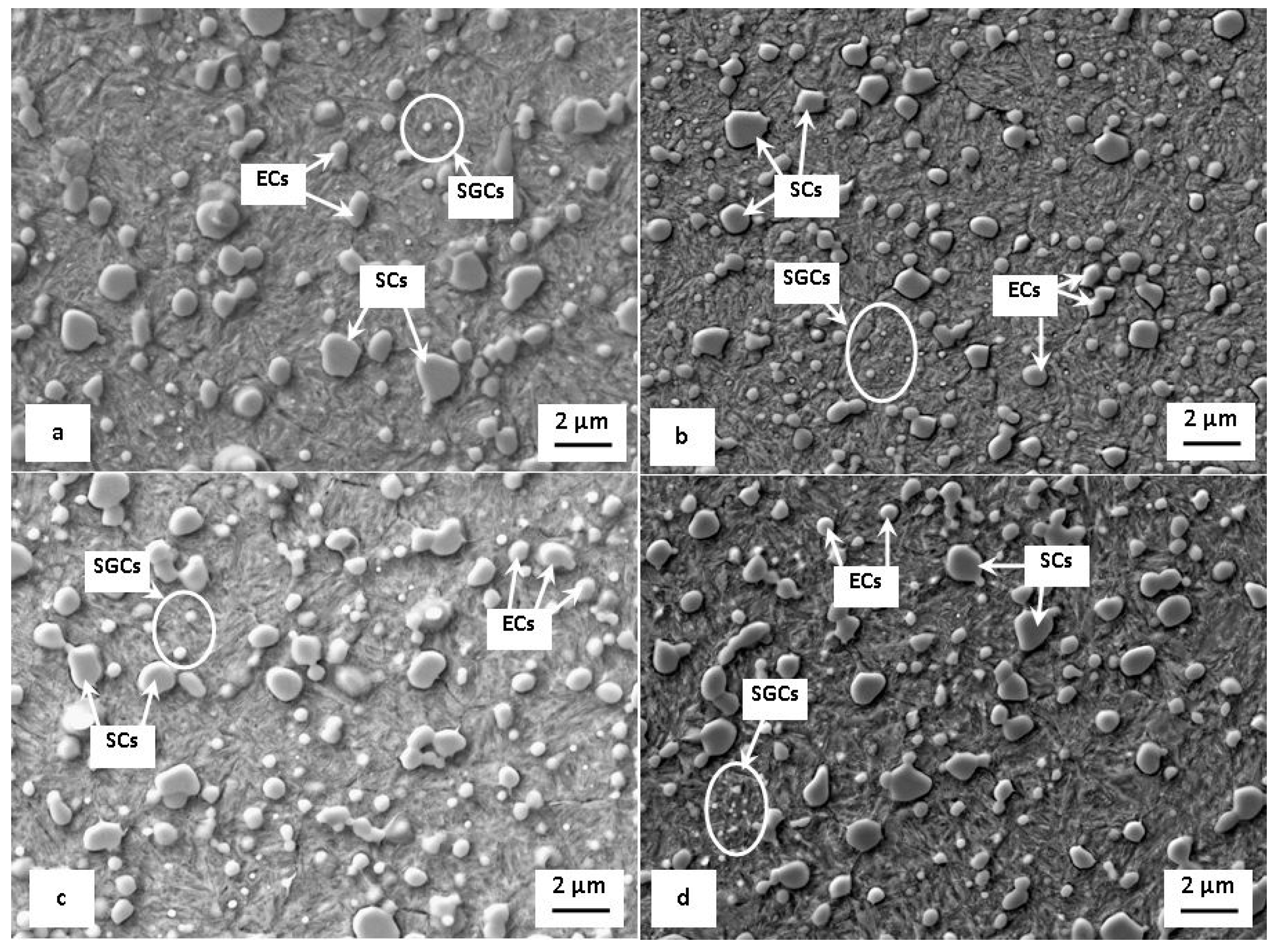
Figure 5.
Population density of SGCs in CHT and different SZT specimens after tempering at 170 °C: (a) CHT, (b) SZT at −140 °C, (c) SZT at −196 °C, and (d) SZT at −269 °C.
Figure 5.
Population density of SGCs in CHT and different SZT specimens after tempering at 170 °C: (a) CHT, (b) SZT at −140 °C, (c) SZT at −196 °C, and (d) SZT at −269 °C.

Figure 6.
Hardness of CHT and differently SZT specimens made of Vanadis 6 steel in dependence on tempering temperature.
Figure 6.
Hardness of CHT and differently SZT specimens made of Vanadis 6 steel in dependence on tempering temperature.

Figure 7.
Flexural strength for CHT and differently SZT treated specimens made of Vanadis 6 steel.

Figure 8.
Work of fracture Wof for CHT and differently SZT treated specimens made of Vanadis 6 steel.
Figure 8.
Work of fracture Wof for CHT and differently SZT treated specimens made of Vanadis 6 steel.
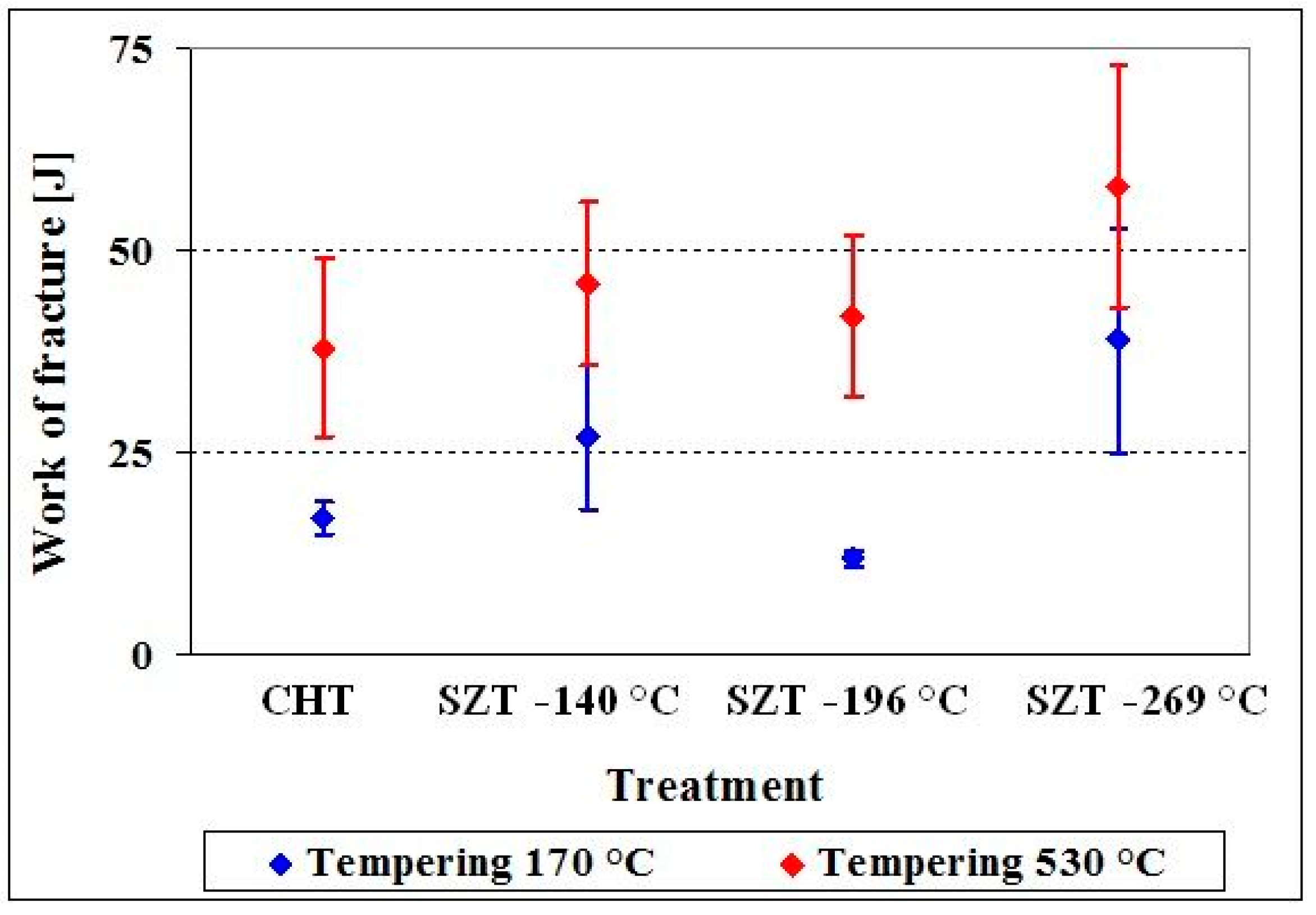
Figure 9.
SEM micrographs showing the fracture surfaces of the specimens for flexural strength after tempering at 170 °C: (a) CHT, (b) SZT at −140 °C, (c) SZT at −196 °C, and (d) SZT at −269 °C.
Figure 9.
SEM micrographs showing the fracture surfaces of the specimens for flexural strength after tempering at 170 °C: (a) CHT, (b) SZT at −140 °C, (c) SZT at −196 °C, and (d) SZT at −269 °C.
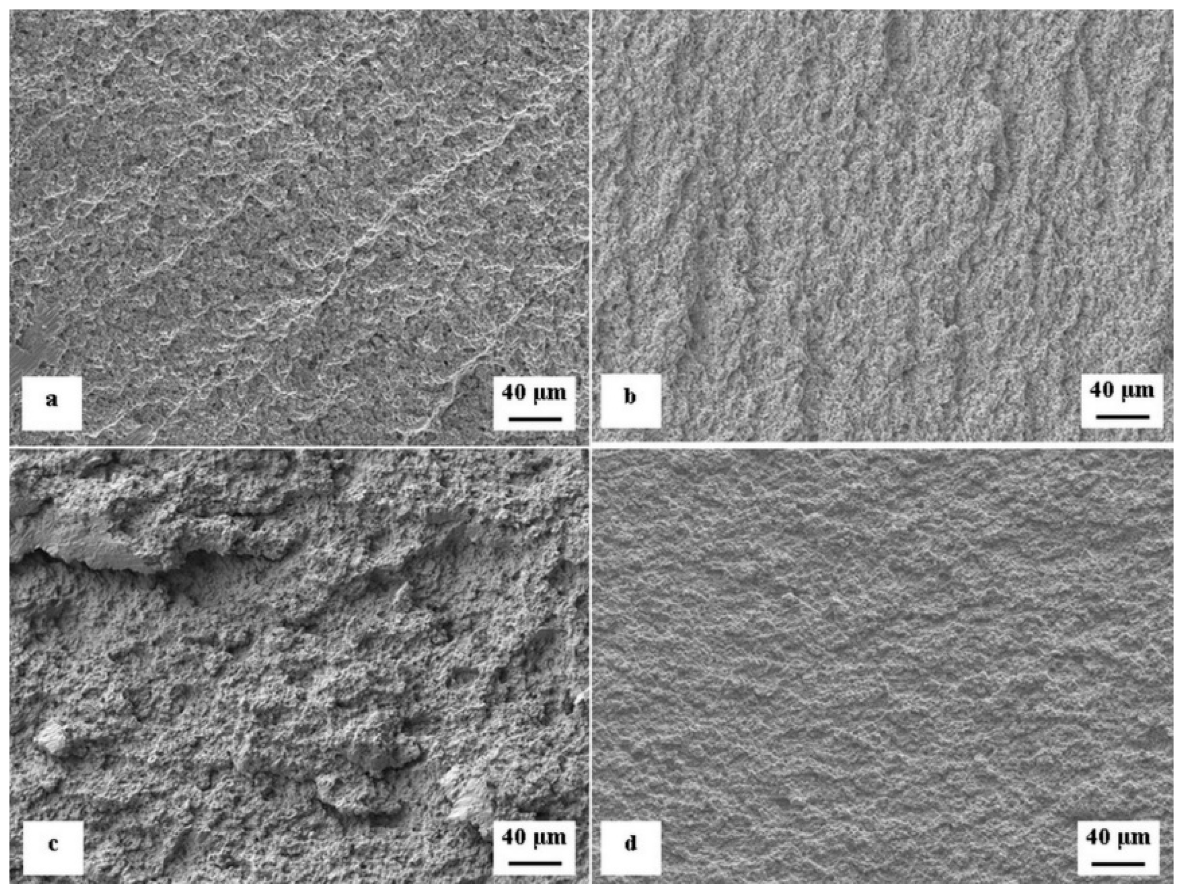
Figure 10.
SEM micrographs showing details of the fracture surfaces of the specimens for the flexural strength after tempering at 170 °C: (a) CHT, (b) SZT at −140 °C, (c) SZT at −196 °C, and (d) SZT at −269 °C. DC—decohesion at the matrix/carbide interface; FCs—fractured carbides; PLD—plastic deformation; CL—cleavage fracture mode.
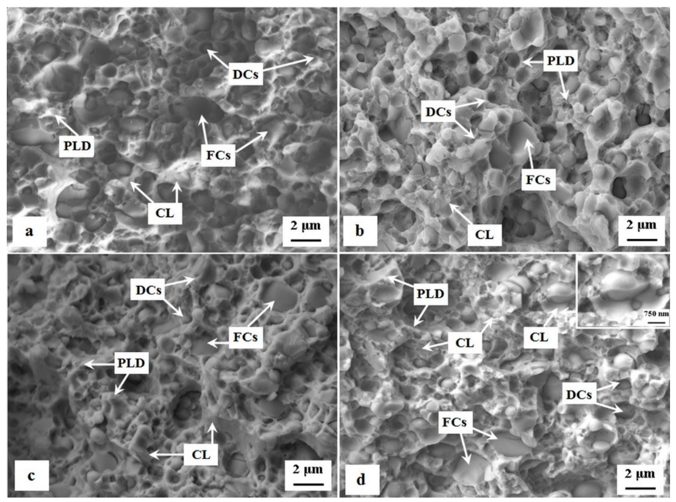
Figure 11.
SEM micrographs showing details of fracture surfaces of the broken specimens for flexural strength after tempering at 530 °C: (a) CHT, (b) SZT at −140 °C, (c) SZT at −196 °C, and (d) SZT at −269 °C.
Figure 11.
SEM micrographs showing details of fracture surfaces of the broken specimens for flexural strength after tempering at 530 °C: (a) CHT, (b) SZT at −140 °C, (c) SZT at −196 °C, and (d) SZT at −269 °C.

Figure 12.
Retained austenite amount in CHT and differently SZT specimens after tempering at 170 °C: (a) CHT, (b) SZT at −140 °C, (c) SZT at −196 °C, and (d) SZT at −269 °C.
Figure 12.
Retained austenite amount in CHT and differently SZT specimens after tempering at 170 °C: (a) CHT, (b) SZT at −140 °C, (c) SZT at −196 °C, and (d) SZT at −269 °C.

Figure 13.
Fracture toughness for differently heat-treated specimens made of Vanadis 6 steel.

© 2018 by the authors. Licensee MDPI, Basel, Switzerland. This article is an open access article distributed under the terms and conditions of the Creative Commons Attribution (CC BY) license (http://creativecommons.org/licenses/by/4.0/).
Share and Cite
MDPI and ACS Style
Jurči, P.; Dlouhý, I.; Priknerová, P.; Mrštný, Z. Effect of Sub-Zero Treatment Temperatures on Hardness, Flexural Strength, and Fracture Toughness of Vanadis 6 Ledeburitic Die Steel. Metals 2018, 8, 1047. https://doi.org/10.3390/met8121047
AMA Style
Jurči P, Dlouhý I, Priknerová P, Mrštný Z. Effect of Sub-Zero Treatment Temperatures on Hardness, Flexural Strength, and Fracture Toughness of Vanadis 6 Ledeburitic Die Steel. Metals. 2018; 8(12):1047. https://doi.org/10.3390/met8121047
Chicago/Turabian StyleJurči, Peter, Ivo Dlouhý, Petra Priknerová, and Zdeněk Mrštný. 2018. "Effect of Sub-Zero Treatment Temperatures on Hardness, Flexural Strength, and Fracture Toughness of Vanadis 6 Ledeburitic Die Steel" Metals 8, no. 12: 1047. https://doi.org/10.3390/met8121047
Note that from the first issue of 2016, this journal uses article numbers instead of page numbers. See further details here.