Mechanical Properties of Thixoforged In Situ Mg2Sip/AM60B Composite at Elevated Temperatures


1
State Key Laboratory of Advanced Processing and Recycling of Nonferrous Metals, Lanzhou University of Technology, Lanzhou 730050, China
2
Shandong Key Laboratory for High Strength Lightweight Metallic Materials, Qilu University of Technology (Shandong Academy of Science), Jinan 250014, China
*
Author to whom correspondence should be addressed.
Metals 2018, 8(2), 106; https://doi.org/10.3390/met8020106
Submission received: 8 December 2017
/
Revised: 24 January 2018
/
Accepted: 29 January 2018
/
Published: 2 February 2018
(This article belongs to the Special Issue Metal Matrix Composites)
Abstract
:The mechanical behaviors of the thixoforged in situ Mg2Sip/AM60B composite at elevated temperatures were evaluated. The results indicated that the thixoforged composite exhibits higher UTS (ultimate tensile strength) than that of the thixoforged AM60B at the cost of elongation. As the testing temperature rises from 25 to 300 °C, the UTS of both these two materials decreases while their elongations increases. The enhanced dislocation motion ability, the softened eutectic β phase at 120 °C, the activated non-basal slipping and the dynamic recovery and recrystallization mechanisms at 150 °C are responsible for the change in tensile properties with testing temperatures. The fracture mode transforms from the ductile into the brittle as the initial strain rate increases from 0.01 to 0.2 s−1 at 200 °C.
1. Introduction
In the past few years, magnesium alloys have been widely used in the fields of automotion, electronic products, portable tools, sporting goods, and aerospace vehicles owing to their light weight, excellent castability, damping capacity, machinability, and so on [1]. However, the rapid loss of strength at temperatures above 120 °C limits their extended applications [2]. In order to solve this problem, several new heat resistant magnesium alloys have been recently developed [3]. The design in heat resistant magnesium alloys mainly abides by the following ideas: strengthening the α-Mg matrix or/and limiting the cross-slip of dislocations and migration of the grain boundary [4]. Most of the heat resistant magnesium alloys with high performances are achieved through the addition of rare earth elements [5,6,7,8]. Unfortunately, the formidable cost of rare earth elements limits the development of the magnesium industry. The requirements of high-performance and light-weight materials in automotive and aerospace fields have become increasingly urgent in recent years [1], leading the development of heat-resistant magnesium alloys with cost-effective technologies.
Combining the mechanical properties of magnesium alloys with ceramics, magnesium-based composites exhibit a higher service temperature with affordable cost [9,10,11,12]. Therefore, the magnesium-based composites become attractive candidates for the applications at elevated temperatures [13]. However, most of the related investigations focus on the fabrication of magnesium-based composites [14]. The mechanical behaviors of magnesium-based composites at elevated temperatures dramatically influence their performance. Unfortunately, the investigations involving this subject are lagging far behind with the rare earth-contained heat-resistant magnesium alloys [7,15,16]. Generally, there are three strengthening mechanisms for metal-matrix composites: load transfer, Orowan looping, and dislocation strengthening. Every mechanism is changing as the temperature changes. However, this has not been discussed in detail. It can be expected that due to the difference in microstructural constituents and the processing technique, the related fundamental knowledge for magnesium-based composites should also be different. Therefore, the mechanical behaviors of magnesium-based composites at elevated temperatures become an indispensable part for their applications and require sustained research effort.
Thixoforging is a combination of casting and forging, in which the semisolid ingot is injected steadily and solidified under applied pressure [17]. It has been pointed out that thixoforging is especially suitable for the forming of aluminum and magnesium alloys [17,18,19]. Thus, it is theoretically expected that thixoforging should be a maneuverable method to fabricate magnesium-based composites. In the authors’ previous investigations [20,21,22], the ultimate tensile strength (UTS) of the thixoforged in situ Mg2Sip/AM60B composite is 35.6% higher than the thixoforged AM60B alloy at the cost of the elongation. However, the mechanical behaviors at elevated temperatures of this composite have not been studied.
In this experimental paper, the mechanical behaviors at elevated temperatures of the thixoforged in situ Mg2Sip/AM60B composite will be discussed in detail. The informative results are compared to the thixoforged AM60B alloy. The strengthening mechanisms of the Mg2Si particle will also be investigated.
2. Materials and Methods
The raw materials used for this work were commercial AM60B, Al-30 wt % Si, and pure Mg, melted at 790 °C in an electric resistance furnace (Shanghai Shiyan Electric Furnace Co., Ltd., Shanghai, China). In order to avoid oxidation, the melting was covered by RJ-2 (Hongguang Co., Ltd., Shanghai, China), which was designed for magnesium alloys. Then, 0.5 wt % Sr (using Mg-30Sr master alloy) was added into the melting in order to modify the Mg2Si phase. After the melt was held for 20 min, 0.2% SiCp (using pressed cake of Mgp-25SiCp mixture powders) was introduced and stirred for 3 min for purpose of refining the α-Mg phases. Subsequently, the melt was degassed using C2Cl6 and pouring into a steel mold with a cavity of ф 50 mm × 500 mm. Thus, the as-cast ingots were obtained.
Some small ingots were cut from the as-cast ingots, with dimensions of ф 42 mm × 30 mm. Those ingots were reheated in a resistance furnace at 600 °C for 60 min and the semisolid ingots were obtained. The semisolid ingots were transferred into the bottom die, which was preheated to 300 °C with a cavity of ф 50 mm × 40 mm. Then the die was closed, driven by the hydraulic pressing machine (Tianjin Tianduan Press Co., Ltd., Tianjin, China). The pressure of 192 MPa forced on the semisolid ingot increased to the setting value within 5 s and held for 20 s. Repeating the above experiment, thixoforged composites were obtained. The thixoforged AM60B alloys were also prepared by this method.
According to the standard of GB/T 4338-2006, some tensile specimens were machined using the wire-cut machine (Fangzheng CNC Machine Tool Co., Ltd., Taizhou, China) from the center of the thixoforged products and parallel to the pressure. The gauge dimensions of the specimens were 10 mm × 1.2 mm × 2.5 mm. The tensile testing was conducted in a universal material testing machine with a heating device, of which the temperature control precision is ±1 °C. The tensile specimen was heated at the setting temperature for 10 min, and then the test was conducted. In view of the servicing temperature of the magnesium alloys [2,3], which is no more than 300 °C, the tensile testing was carried out under the temperatures of 25 (room temperature), 100, 150, 200, 250, and 300 °C at cross head speeds of 1.0 mm·s−1, and at cross head speeds of 0.1, 0.5, 1.5, and 2 mm·s−1 under 200 °C, respectively. The corresponding initial strain rates were 0.01, 0.05, 0.1, 0.15, and 0.2 s−1. The average of at least five testing values was taken as the tensile properties of a thixoforged composite. Some typical fracture surfaces, and side views of them, were also observed on the scanning electron microscope (SEM; NEC Electronics Corporation, Tokyo, Japan) and the optical microscope (OM; Nikon Instruments Co., Ltd., Shanghai, China). Microstructural specimens were cut from the center of each of the thixoforged products. One cross-section parallel to the pressure direction was prepared under standard metallographic procedures. Microstructural characterization was also carried out with this OM. The typical images were quantitatively examined by Image-Pro Plus 5.0 software (5.0, Media Cybernetics Co., Ltd., Silver Spring, MD, USA), the fraction of the Mg2Si particles to the whole was taken as its volume fraction.
3. Results
3.1. Microstructures of As-Cast, Semisolid, and Thixoforged Composite and Thixoforged AM60B Alloy
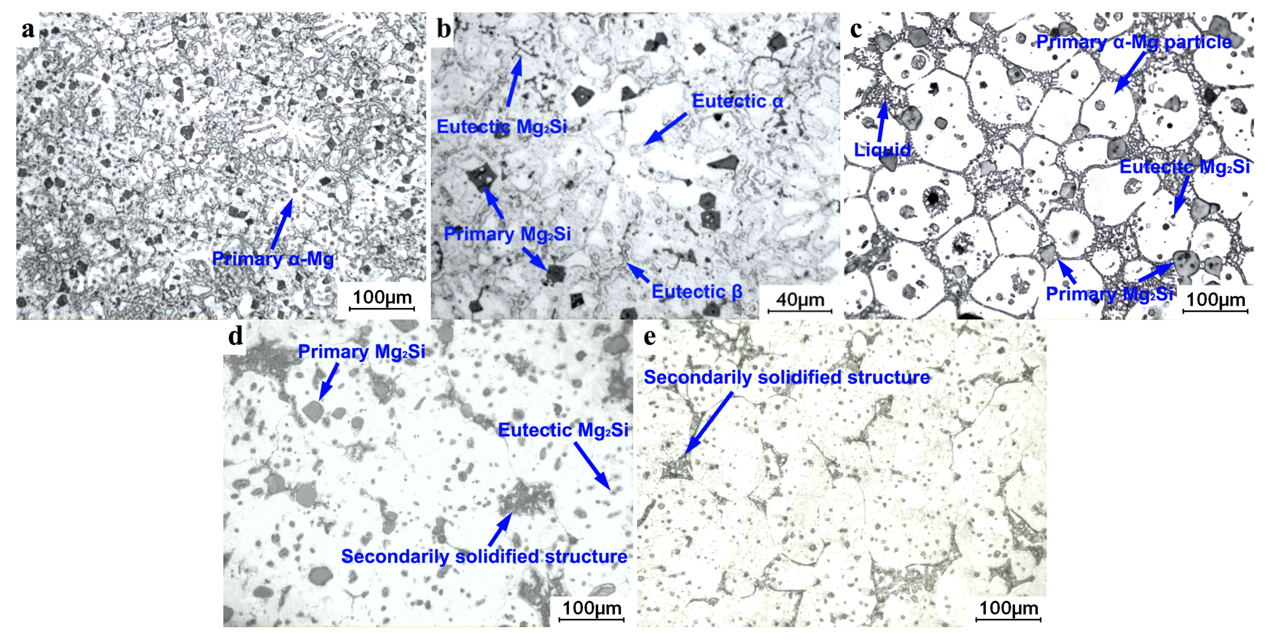
In order to identify the microstructures of the thixoforged composite, the initial as-cast microstructures and its solidifying process should be first clarified. As shown in Figure 1a,b, the microstructure of the as-cast composite contains primary Mg2Si particles, primary α-Mg dendrites, eutectic Mg2Si particles, and eutectic structures. Together with the well-known solidifying process of AM60B, the solidification of this composite begins with the precipitation of the primary Mg2Si particles and then the primary α-Mg phases. The first-formed Mg2Si particles are pushed by the growing primary α-Mg phases and distribute in the residual eutectic liquid. Finally, the eutectic liquid solidifies into eutectic structures. During the last stage of the solidification, the eutectic Mg2Si phases separate out previously from the eutectic liquid, then the eutectic α-Mg phases preferentially grow up on the surface of the primary α-Mg dendrites, and the eutectic β phases (Mg17Al12) are left in the interdendritic regions.
After the composite is reheated at 600 °C for 60 min, the α-Mg dendrites evolve into the α-Mg particles, and the sharp edges and corners of the Mg2Si particles are obviously blunted. Both of them are suspended in the liquid (shown in Figure 1c). The microstructural evolution of α-Mg dendrites and Mg2Si particles during partial remelting have been discussed in detail in the previous works [23]. Subsequently, the semisolid ingot is thixoforged. Therefore, the liquids solidify into secondary solidified structures. As shown in Figure 1d,e, the microstructures of the thixoforged composite and AM60B alloy consist of primary α-Mg particles (in bright color) and secondary solidified structures. The amount of the secondary solidified structures is significantly less than that of the liquids in the semisolid microstructures. This phenomenon results from the solidified characteristics of the semisolid ingot. The secondary α-Mg phases (to differentiate from the primary α-Mg particles, the α-Mg phases solidified from the liquids is named as secondary α-Mg phases) preferentially grow on the surfaces of the primary α-Mg particles without boundaries. In this case, it is difficult to separate these two phases from each other and results in the secondary solidified structures seemingly less than the liquids in the semisolid ingot. Additionally, the thixoforged composite contains the reinforcement of Mg2Si particles, of which the volume fraction is about 10 vol % (Figure 1d). There are two kinds of Mg2Si particles in Figure 1d. The larger ones are the primary Mg2Si particles, the size of which ranges from 20 to 40 μm. The smaller ones are eutectic Mg2Si particles, the size of which is less than 10 μm. Most of the primary Mg2Si particles locate at the boundary of the α-Mg particles, and only a few of them locate inside. The eutectic Mg2Si particles mainly distribute within the α-Mg particles. The amount of the primary Mg2Si particle is obviously larger than that of the eutectic Mg2Si particles. These are attributed to the following reasons: The first is the amount of the formed eutectic Mg2Si particles is less than the primary Mg2Si particles, since the eutectic point of the Mg-Si system is 1.38% [24,25]. On the other hand, the morphological evolution of the Mg2Si particles obey the Ostwald ripening mechanism during partial remelting, which refers to the dissolution of small-sized grains and the growth of large particles [26]. Owing to the dissolution and subsequent reprecipitation, the amount of eutectic Mg2Si particles decreases and the primary Mg2Si particles becomes blunt. Based on the abovementioned, the distribution of the Mg2Si particles can easily understood.
3.2. Tensile Properties of the Thixoforged Composite at Different Testing Temperatures
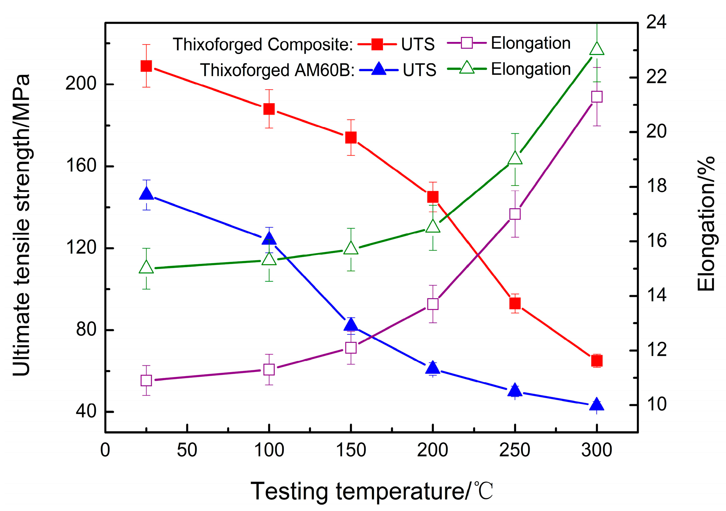
Figure 2 reveals the tensile properties of the thixoforged composite and AM60B at different testing temperatures. It indicates that the UTS of the thixoforged composite is always higher than that of the thixoforged AM60B, and both of them always decrease as the temperature rises. However, the elongation of the thixoforged AM60B is always higher than that of the thixoforged composite, and both of them increase as the temperature rises.
Figure 3 presents the fractographs of the thixoforged composite tested at different temperatures. As shown in Figure 3a, the fracture surface is covered by innumerable small dimples and damaged Mg2Si particles. There are two kinds of damaged Mg2Si particles: either debonded from the matrix (marked by A), or broken into pieces (marked by B). Figure 4a indicates that the number of the former ones (marked by A) is much fewer than the latter ones (marked by B), owing to the differences of the crystal structures and the lattice constants between the Mg2Si particles and the α-Mg phases, the interface of which belongs to an incoherent interface [27]. During deformation, the soft α-Mg phases deform plastically and the Mg2Si particles deform elastically. Thus, a large stress concentration preferentially generates near this interface, and increases to 2–4 times higher than the surrounding matrix [28,29]. Finally, the stress concentration results in the interfacial debonding or/and fragmentation of the Mg2Si particles. Of course, the stress concentration is relaxed. Thus, it can be expected that the Mg2Si particles strengthen the matrix through the load transfer mechanism, which results in the excellent UTS of the thixoforged composite at room temperature (Figure 2).
It has been reported that the β phase (Mg17Al12) is softened at temperatures above 120 °C [30]. Therefore, the UTS of the thixoforged AM60B decreases at 150 °C owing to the absence of a reinforcing phase for the matrix (Figure 2). As mentioned above, the Mg2Si particle always locates in the last solidified regions [20], i.e., surrounded by the eutectic phase. Thus, the softening of the eutectic β phase leads to the decrease in the interfacial bonding strength between the Mg2Si particles and the matrix. As shown in Figure 4b, the interfacial debonding (marked by A) gradually becomes dominant. However, the broken Mg2Si particles (marked by B) still exist in the fracture surface (Figure 3b). Thus, the Mg2Si particles still contribute in strengthening the matrix. Therefore, the UTS of the thixoforged composite is much higher than that of the thixoforged AM60B (Figure 2). Moreover, the non-basal slip system of the magnesium alloy is activated at this temperature [31,32], which significantly promotes the plastic deformation ability of α-Mg phase. Correspondingly, the size of the dimples in the fracture surface at the testing temperature of 150 °C becomes large (Figure 3b).
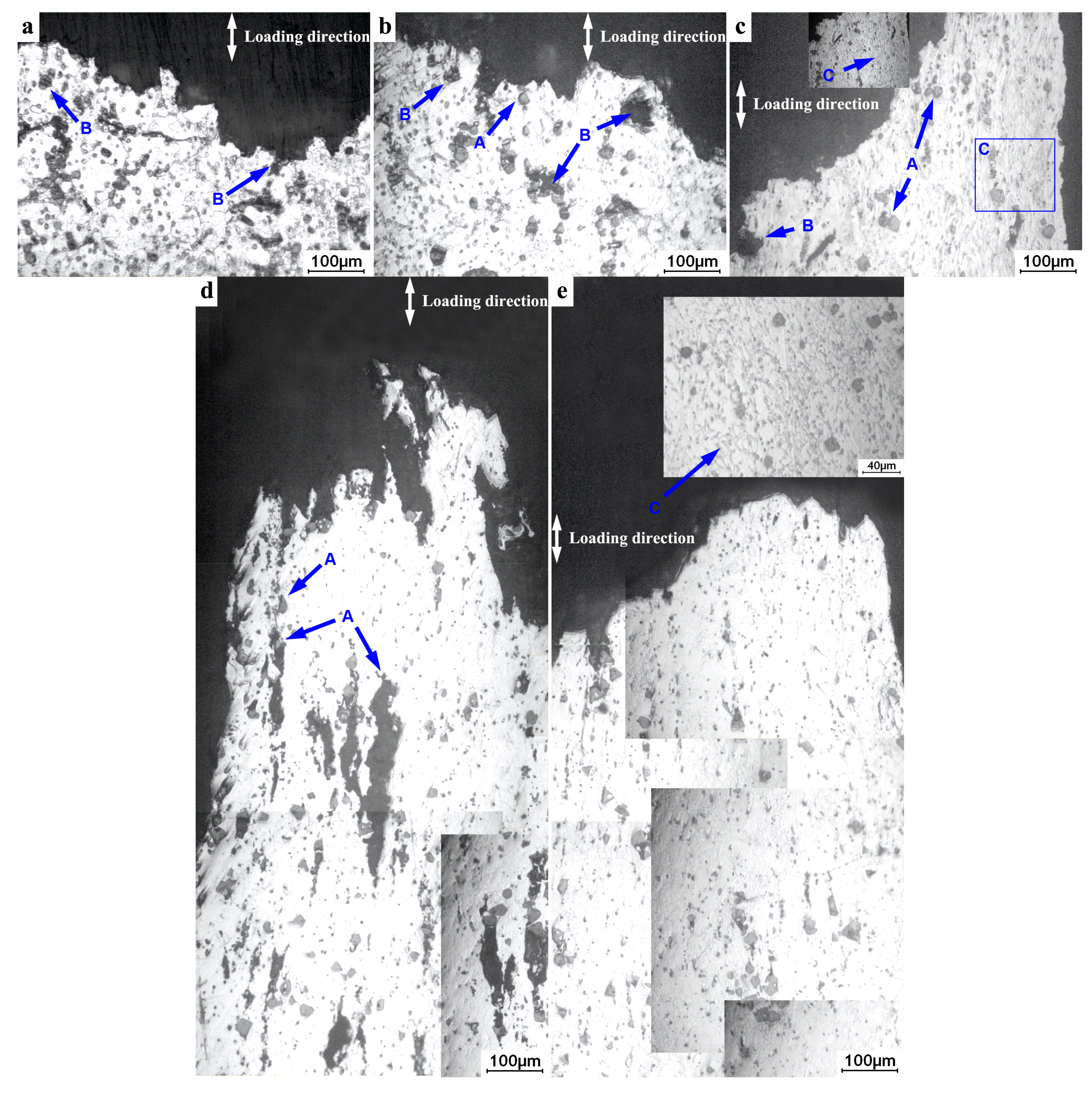
As shown in Figure 3c, those dimples transform into large pits, and deep holes form in the fracture surface at a testing temperature of 200 °C. The Mg2Si particle always locates to the bottom of these holes (marked by A). As the testing temperature reaches 200 °C, the dislocation motion is promoted from the accelerated atom diffusion ability. Moreover, the non-basal slipping is further active. Both of these lead to the decrease in UTS and the increase in elongation (Figure 2). Therefore, the dimples easily connect with each other, and then the large-sized pits are generated (Figure 3c). In addition, the broken Mg2Si particles are seldom found in the fracture surface, and the side view of it (Figure 3c and Figure 4c). That is, the Mg2Si particles mainly debond from the matrix (marked by A in Figure 4c). Subsequently, the surrounding matrix continually plastically deforms as the tensile testing proceeds. Then, the holes, of which the Mg2Si particle locates to the bottom, are thereby generated (Figure 3c). In addition, as shown in Figure 4c, a kind of texture-like microstructure is formed (marked by C in Figure 4c). Although the critical temperature for recrystallization of the magnesium alloys is 230 °C [33,34], in view of the tensile testing belonging to a dynamic process, it should be suggested that the formation of the texture-like microstructures are attributed to the dynamic recovery and recrystallization regimes, which also result in the decrease of UTS and the increase of elongation of the magnesium alloy. Under the combined effects mentioned above, the UTS of the thixoforged composite apparently decrease and its elongation continually increases (Figure 2).
When the testing temperature reaches 250 °C, the fracture surface is characterized by the necking feature (as shown in Figure 3d). This implies that the plastic deformation ability of the α-Mg phase is further improved (Figure 2). The combining effects are enhanced as the testing temperature increases, which are responsible for the improved plastic deformation ability. Therefore, the holes’ characterization becomes more dominant on the fracture surface instead of those large-sized pits (compare Figure 3d to Figure 3c). Figure 4d displays that these holes are also generated inside the tensile bar (marked by A). This implies that the Mg2Si particles cannot bear much stress concentration due to the interfacial debonding. Therefore, the load transfer mechanism is decreasingly effective. In this case, the UTS of the thixoforged composite rapidly decreases while its elongation further increases (Figure 2). Even so, the UTS of the thixoforged composite is still higher than that of the AM60B (Figure 2). Thus, it can be expected that the other strengthening mechanisms should take part in reinforcing the matrix and this will be discussed in detail at the Section 3.3.
The fracture surface shown in Figure 3e is characterized by the necking feature as well. However, the debonded Mg2Si particle is seldom observed and the amount of the texture-like microstructure (marked by C) is increased at the side view of fracture surface (Figure 4e). When the testing temperature further rises to 300 °C, the dynamic recovery and recrystallization mechanisms are further promoted [35]. Thus, the amount of the texture-like microstructure increases. In this case, the stress concentration near the interface between the Mg2Si particles and the matrix is easily relaxed through the formation of the texture-like microstructures (marked by C in Figure 4e). As a result, the interfacial debonding disappears. Moreover, the non-basal slip system of the magnesium alloys is completely activated at 300 °C [31], which results in the further decrease in UTS and the increase in elongation (Figure 2). The tensile properties of both thixoforged composite and AM60B are at a comparative level (as shown in Figure 2), which implies the strengthening mechanisms from the Mg2Si particle for the matrix becomes invalid when the testing temperature reaches 300 °C.
3.3. Strengthening Mechanisms of the Mg2Si Particle
In order to verify the strengthening mechanisms, a typical fracture surface, and a side view of it showing the Mg2Si particles, are presented in Figure 5. The Mg2Si particle is broken into pieces (Figure 5a) and there are no visible cracks in the surrounding matrix (Figure 5b). That is, the load transfer mechanism from the Mg2Si particle effectively protects the matrix from the crack initiation. With the testing temperature rising, the broken degree of the Mg2Si particle is reduced. As shown in Figure 5c, the Mg2Si particle only splits into two parts, and even transforms into interfacial debonding as the temperature further increases (Figure 5d). Namely, this mechanism is decreasing, due to the reduced bonding strength of the interface between the Mg2Si particle and the matrix as the testing temperature rises. However, the UTS of the thixoforged composite is always higher than that of the thixoforged AM60B (Figure 2). It can be expected that the other mechanisms take part in reinforcing the thixoforged composite.
As mentioned above, there are two kinds of Mg2Si particles. After tensile testing, the large-sized ones break into pieces and the small-sized ones maintain their original morphology (marked by arrows in Figure 5e). During tensile testing, the interaction between dislocations and fine particles also contributes in strengthening the matrix through the Orowan looping mechanism [29]. As the testing temperature rises, the dislocation motion is promoted from the accelerated atom diffusion ability. In this case, the Orowan looping mechanism operates increasingly as the testing temperature rises. On the other hand, the mismatch in the coefficient of thermal expansion (CTE) between Mg2Si particles and the matrix [36] also strengthens the matrix. During thixoforging and tensile testing at elevated temperatures, the dislocations are created near the Mg2Si/matrix interface due to the relaxation of the thermal expansion mismatch between the Mg2Si particles and matrix. In this case, the dislocation density increases. The dislocations formed during tensile testing increase as the testing temperature rises. Therefore, this mechanism is gradually in action as the testing temperature rises, can impede the dislocation movement, and also plays a very important role in strengthening the matrix.
Although the contribution of each strengthening mechanism has not been calculated separately, it also suggests that an additive or synergetic effect from the combination of several mechanisms is accountable for strengthening the matrix. In comparison, the load transfer mechanism primarily operates at the testing temperature under 200 °C, and the other two grow dominant as the testing temperature further rises.
3.4. Effect of Initial Strain Rate on Tensile Properties
As mentioned in the Section 3.2, the dynamic recovery and recrystallization regimes influence the tensile properties dramatically. The initial strain rate also has large effects on this regime [37,38]. Thus, the mechanical behavior under 200 °C at different initial strain rates is discussed in detail below.
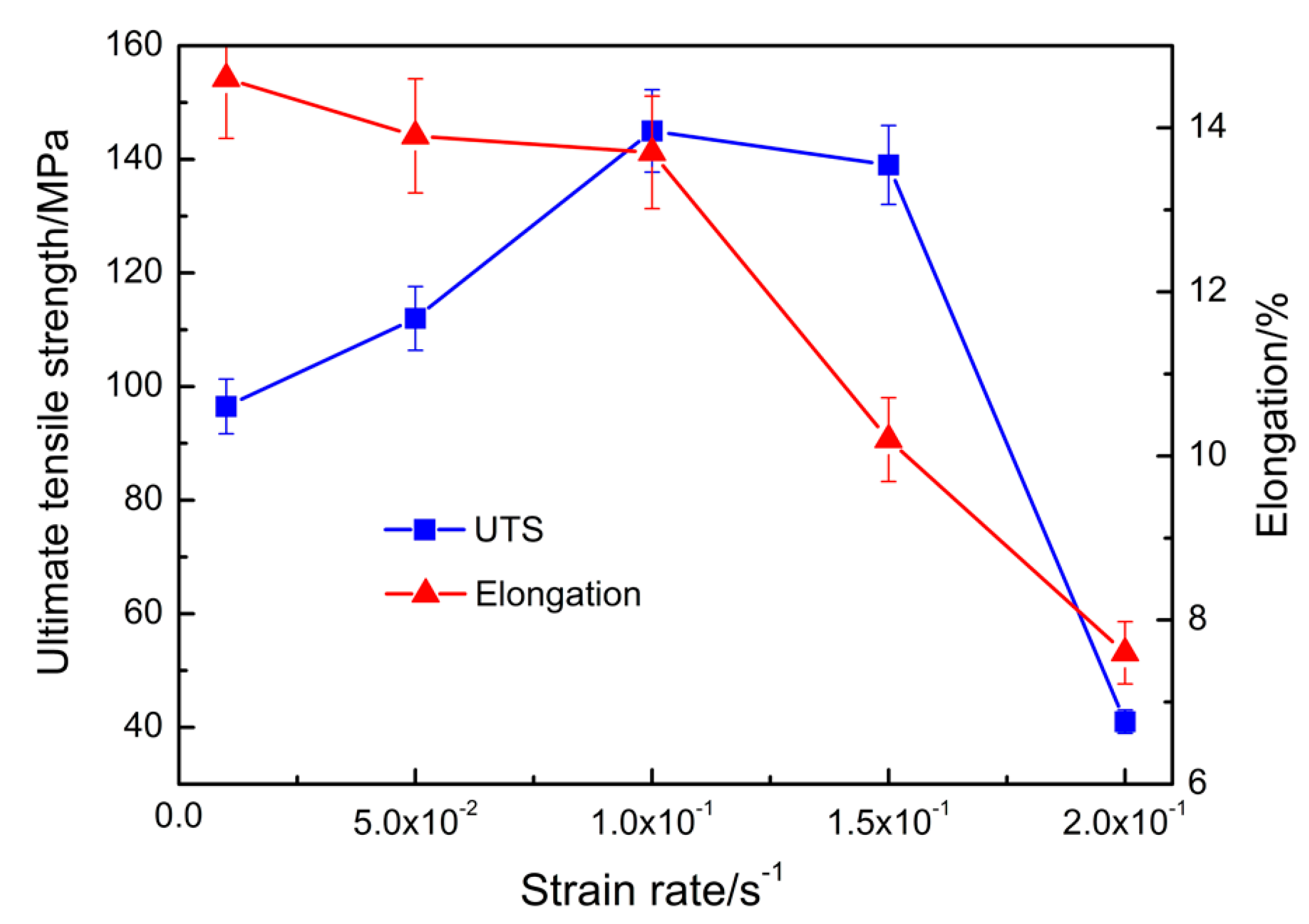
Figure 6 reveals the tensile properties of the thixoforged composite at different initial strain rates. It indicates that the UTS increases to a peak value at 0.1 s−1 and then decreases as the initial strain rate increases from 0.01 to 0.2 s−1. However, the elongation continually decreases.
As shown in Figure 7a, the fracture surface is covered by small and uniform dimples. The crack propagates through the α-Mg phases (Figure 8a). The employed initial strain rate 0.01 s−1 is the lowest initial strain rate. Thus, the dislocation has enough time to move. Therefore, the stress concentration near the interface between the Mg2Si particles and the matrix can be easily relaxed through the dislocation motion regime. As the tensile testing proceeds, the microvoids are generated in the α-Mg phase, and then connect with each other to form dimples. Eventually, the connecting leads to the fracture of the composite. Namely, the fracture mode belongs to ductile fracture mechanism and the fracture of the α-Mg phases results in the final fracture of the composite.
The increase in the initial strain rate leads to the enhanced dynamic recovery and recrystallization mechanisms. Therefore, the texture-like structures are then generated (Figure 4c). This phenomenon results in the softening of α-Mg phases, which leads their improved plastic deformation ability. In this case, these dimples on the fracture surface become large (Figure 3c). However, the stress concentration cannot be relaxed through the dislocation motion owing to the increase of initial strain rate. Thus, the interfacial debonding is obviously observed on the fracture surface (compare Figure 3c with Figure 7a). Moreover, the work hardening mechanism is increasingly promoted as the initial strain rate increases, which takes part in improving the UTS at the cost of the elongation. Consequentially, the UTS is increased while the elongation is decreased as the initial strain rate rises to 0.1 s−1 (Figure 6). The fracture mode also obeys to a ductile fracture mechanism.
Figure 7b presents that the cleavage plane appears on the fracture surface, which implies that the fracture is somewhat brittle in nature. In addition, the Mg2Si particles, which debonded (marked by A) and broke into pieces (marked by B), are obviously observed on the fracture surface and the side view of it (Figure 7b and Figure 8b). The dynamic recovery and recrystallization mechanism, and the work hardening mechanism, are at a competitive situation. The increase in the initial strain rate results in the enhancement of both mechanisms. However, when the initial strain rate exceeds a give value, it lacks enough time to realize the dynamic recovery and recrystallization mechanism in action. Therefore, the amount of the texture-like structures decreases. In this case, the work hardening mechanism becomes dominant and leads to the decrease in elongation (Figure 6). On the other hand, the load transfer mechanism from the Mg2Si particle is also enhanced as the initial strain rate rises. Thus, high stress concentration is preferentially formed near the interface between the Mg2Si particles and the matrix, and results in the interfacial debonding or/and fragmentation of the Mg2Si particles (compare Figure 7b with Figure 3c). Then the cracks are formed. Subsequently, the surrounded matrix deforms. For the magnesium alloys, the deformation is achieved through the intergranular slipping accompanied by intragranular dislocation motion [39]. As the initial strain rate rises, the slipping increasingly dominates due to there being insufficient time for the motion of intragranular dislocation. Therefore, the cleavage planes are generated on the fracture surface. The slipping cannot bear much deformation and, thus, the resultant elongation significantly decreases (Figure 6). Correspondingly, the fracture mode transforms into a quasi-cleavage mode.
As the initial strain rate further rises, a high stress concentration is very quickly generated at the interface between the Mg2Si particles and the matrix. Thus, the interfacial debonding occurs at the early stage of the deformation. Namely, the cracks are thereby formed. Then, the cracks propagate into the matrix, leading to the final fracture. It has been reported that there are three mechanisms responsible for the deformation of the magnesium alloy and the critical resolved shear stress (CRSS) from small to large, in sequence, are: basal slipping, twinning, and non-basal slipping [40]. Generally, the CRSS of the basal slipping and twinning are irrelevant to the initial strain rate while that of the non-basal slipping increases as the initial strain rate rises [41]. Therefore, it can be expected that the deformation of the matrix is completely through the basal slipping of the α-Mg phases. In this case, the fracture surface is characterized by the brittle feature (Figure 7c). Owing to the formation of crack and the deformation mechanism of the α-Mg phase, the resultant UTS and elongation of the composite are rapidly decreased (Figure 6).
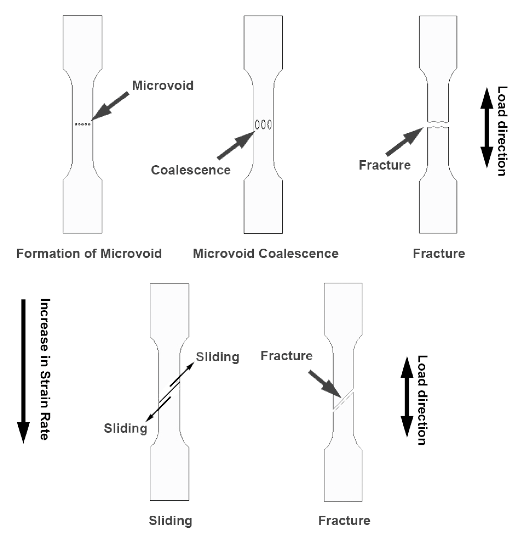
Based on the abovementioned, the fracture mode of the composite under different initial strain rates can be summarized by Figure 9. It indicates that the fracture mode gradually transforms from ductile into brittle as the initial strain rate increases from 0.01 to 0.2 s−1. The microvoid coalescence and the sliding are responsible for the fractures under these two conditions, respectively.
4. Conclusions
1. The thixoforged in situ Mg2Sip/AM60B composite exhibits a higher UTS than that of the thixoforged AM60B at the cost of elongation. The super UTS of the thixoforged in situ Mg2Sip/AM60B composite is mainly attributed to the load transfer mechanism and the obstruction for the dislocation motion from the reinforcement Mg2Si particles.
2. As the testing temperature rises, the UTS of both the thixoforged in situ Mg2Sip/AM60B composite and AM60B decrease while their elongation increases. The enhanced dislocation motion ability, the softened eutectic β phase at 120 °C, the activated non-basal slipping, and the dynamic recovery and recrystallization mechanisms at 150 °C are responsible for the change in tensile properties with testing temperatures.
3. The tensile properties change with the initial strain rate changes tested at 200 °C. The UTS of the composite reaches its peak value at the initial strain rate of 0.1 s−1 and then decreases, however, the elongation of the composite continually decreases as the initial strain rate increases. The variations in tensile properties result from the dynamic recovery, recrystallization mechanisms and working hardening.
4. The fracture of the composite transforms from the ductile regime into the quasi-cleavage mode, and finally exhibits the brittle feature as the initial strain rate increases.
Acknowledgments
The authors wish to express thanks to financial support from the National Basic Research Program of China (Grant No. G2010CB635106), the Program for New Century Excellent Talents in University of China (Grant No. NCET-10-0023), and the Program for Hongliu Outstanding Talents of Lanzhou University of Technology.
Author Contributions
Suqing Zhang and Tijun Chen conceived and designed the experiments; Jixue Zhou performed the experiments; Tao Li and Kaiming Cheng analyzed the data; Dapeng Xiu contributed analysis tools; and Suqing Zhang wrote the paper.
Conflicts of Interest
The authors declare no conflict of interest.
References
- Aghion, E.; Bronfin, B.; Eliezer, D. The role of the magnesium industry in protecting the environment. J. Mater. Process. Technol. 2001, 117, 381–385. [Google Scholar] [CrossRef]
- Luo, A.; Pekguleryuz, M.O. Cast magnesium alloys for elevated temperature applications. J. Mater. Sci. 1994, 29, 5259–5271. [Google Scholar] [CrossRef]
- Zhu, S.; Easton, M.; Abbott, T.; Nie, J.; Dargusch, M.; Hort, N.; Gibson, M. Evaluation of magnesium die-casting alloys for elevated temperature applications: Microstructure, tensile properties, and creep resistance. Metall. Mater. Trans. A 2015, 46, 3543–3554. [Google Scholar] [CrossRef]
- Aghion, E.; Bronfin, B.; Eliezer, D. The art of developing new magnesium alloys for high temperature applications. Mater. Sci. Forum 2003, 419, 407–417. [Google Scholar] [CrossRef]
- Weiss, D.; Kaya, A.A.; Aghion, E.; Eliezer, D. Microstructure and creep properties of a cast Mg–1.7% wt rare earth–0.3% wt Mn alloy. J. Mater. Sci. 2002, 37, 5371–5379. [Google Scholar] [CrossRef]
- Zhang, J.; Leng, Z.; Zhang, M.; Meng, J.; Wu, R. Effect of Ce on microstructure, mechanical properties and corrosion behavior of high-pressure die-cast Mg–4Al-based alloy. J. Alloys Compd. 2011, 509, 1069–1078. [Google Scholar] [CrossRef]
- Hu, H. Squeeze casting of magnesium alloys and their composites. J. Mater. Sci. 1998, 33, 1579–1589. [Google Scholar] [CrossRef]
- Nguyen, Q.B.; Gupta, M. Increasing significantly the failure strain and work of fracture of solidification processed AZ31B using Nano-Al2O3 particulates. J. Alloys Compd. 2008, 459, 244–250. [Google Scholar] [CrossRef]
- Chen, L.; Yao, Y. Processing, microstructures, and mechanical properties of magnesium matrix composites: A review. Acta Metall. Sin. (Engl. Lett.) 2014, 27, 762–774. [Google Scholar] [CrossRef]
- Ye, H.Z.; Liu, X.Y. Review of recent studies in magnesium matrix composites. J. Mater. Sci. 2004, 39, 6153–6171. [Google Scholar] [CrossRef]
- Shen, M.; Ying, T.; Chen, F.; Hou, J. Effect of micro- and nano-SiC particulate reinforcements in magnesium-based metal matrix composites. J. Mater. Eng. Perform. 2016, 25, 2222–2229. [Google Scholar] [CrossRef]
- Guo, W.; Wang, D.; Fu, Y.; Zhang, L.; Wang, Q. Dry sliding wear properties of AZ31-Mg2Si magnesium matrix composites. J. Mater. Eng. Perform. 2016, 25, 4109–4114. [Google Scholar] [CrossRef]
- Lloyd, D.J. Particle reinforced aluminium and magnesium matrix composites. Int. Mater. Rev. 1994, 39, 1–23. [Google Scholar] [CrossRef]
- Nie, K.B.; Wang, X.J.; Wu, K.; Xu, L.; Zheng, M.Y.; Hu, X.S. Fabrication of SiC particles-reinforced magnesium matrix composite by ultrasonic vibration. J. Mater. Sci. 2012, 47, 138–144. [Google Scholar] [CrossRef]
- Zhou, S.; Deng, K.; Li, J.; Shang, S.; Liang, W.; Fan, J. Effects of volume ratio on the microstructure and mechanical properties of particle reinforced magnesium matrix composite. Mater. Des. 2014, 63, 672–677. [Google Scholar] [CrossRef]
- Das, A.; Harimkar, S.P. Effect of graphene nanoplate and silicon carbide nanoparticle reinforcement on mechanical and tribological properties of spark plasma sintered magnesium matrix composites. J. Mater. Sci. Technol. 2014, 30, 1059–1070. [Google Scholar] [CrossRef]
- Xia, K.; Tausig, G. Liquidus casting of a wrought aluminum alloy 2618 for thixoforming. Mater. Sci. Eng. A 1998, 246, 1–10. [Google Scholar] [CrossRef]
- Zhao, Z.D.; Chen, Q.A.; Tang, Z.J.; Hu, C.K. Microstructural evolution and tensile mechanical properties of AM60B magnesium alloy prepared by the SIMA route. J. Alloys Compd. 2010, 497, 402–411. [Google Scholar] [CrossRef]
- Liu, D.; Atkinson, H.V.; Kapranos, P.; Jirattiticharoean, W.; Jones, H. Microstructural evolution and tensile mechanical properties of thixoformed high performance aluminium alloys. Mater. Sci. Eng. A 2003, 361, 213–224. [Google Scholar] [CrossRef]
- Zhang, S.; Chen, T.; Cheng, F.; Li, P. A comparative characterization of the microstructures and tensile properties of as-cast and thixoforged in situ AM60B-10 vol % Mg2Sip composite and thixoforged AM60B. Metals 2015, 5, 457–470. [Google Scholar] [CrossRef]
- Zhang, S.; Chen, T.; Cheng, F.; Li, L. Effects of mould temperature on microstructure and tensile properties of thixoforged Mg2Sip/AM60B in-situ composites. J. Alloys Compd. 2015, 657, 582–592. [Google Scholar] [CrossRef]
- Zhang, S.; Chen, T.; Li, P. Microstructure and tensile properties of in situ Mg2Sip/AM60B composite prepared by thixoforging technology. J. Mater. Res. 2016, 31, 783–796. [Google Scholar] [CrossRef]
- Zhang, S.; Chen, T.; Cheng, F.; Li, L. Microstructural evolution and phase transformation during partial remelting of in-situ Mg2Sip/AM60B composite. Trans. Nonferr. Met. Soc. China 2016, 26, 1564–1573. [Google Scholar] [CrossRef]
- Mabuchi, M.; Kubota, K.; Higashi, K. Elevated temperature mechanical properties of magnesium alloys containing Mg2Si. Mater. Sci. Technol. 1996, 12, 35–39. [Google Scholar] [CrossRef]
- Li, G.H.; Gill, H.S.; Varin, R.A. Magnesium silicide intermetallic alloys. Metall. Mater. Trans. A 1993, 24, 2383–2391. [Google Scholar] [CrossRef]
- Snyder, V.A.; Alkemper, J.; Voorhees, P.W. The development of spatial correlations during Ostwald ripening: A test of theory. Acta Mater. 2000, 48, 2689–2701. [Google Scholar] [CrossRef]
- Yu, B.; Chen, D.; Tang, Q.; Wang, C.; Shi, D. Structural, electronic, elastic and thermal properties of Mg2Si. J. Phys. Chem. Solids 2010, 71, 758–763. [Google Scholar] [CrossRef]
- Arsenault, R.J. Interfaces in metal matrix composites. Scr. Metall. 1984, 18, 1131–1134. [Google Scholar] [CrossRef]
- Arsenault, R.J. Strengthening mechanisms in particulate mmc. Scr. Metall. 1991, 25, 2617–2621. [Google Scholar] [CrossRef]
- Eliezer, D.; Aghion, E.; Froes, F. The science, technology, and applications of magnesium. JOM 1998, 50, 30–34. [Google Scholar]
- Kang, F.; Li, Z.; Wang, J.; Cheng, P.; Wu, H. The activation of <c + a> non-basal slip in magnesium alloys. J. Mater. Sci. 2012, 47, 7854–7859. [Google Scholar] [CrossRef]
- Yin, D.D.; Wang, Q.D.; Boehlert, C.J.; Ding, W.J. Creep and fracture behavior of as-cast Mg–11Y–5Gd–2Zn–0.5Zr (wt %). J. Mater. Sci. 2012, 47, 6263–6275. [Google Scholar] [CrossRef]
- Biswas, S.; Singh, D.S.; Beausir, B.; Toth, L.S.; Suwas, S. Thermal response on the microstructure and texture of ECAP and cold-rolled pure magnesium. Metall. Mater. Trans. A 2015, 46, 2598–2613. [Google Scholar] [CrossRef]
- Liu, S.; Gao, F.; Zhang, Q.; Li, W. Mechanical properties and microstructures of nano-sized SiC particles reinforced AZ91D nanocomposites fabricated by high intensity ultrasonic assisted casting. Mater. Sci. Forum 2009, 618–619, 449–452. [Google Scholar] [CrossRef]
- Li, Z.; Dong, J.; Zeng, X.Q.; Lu, C.; Ding, W.J. Influence of Mg17Al12 intermetallic compounds on the hot extruded microstructures and mechanical properties of Mg–9Al–1Zn alloy. Mater. Sci. Eng. A 2007, 466, 134–139. [Google Scholar] [CrossRef]
- Arsenault, R.J.; Shi, N. Dislocation generation due to differences between the coefficients of thermal expansion. Mater. Sci. Eng. A 1986, 81, 175–187. [Google Scholar] [CrossRef]
- Zhang, D.; Yang, X.; Sun, H.; Li, Y.; Wang, J.; Zhang, Z.; Ye, Y.; Sakai, T. Dynamic recrystallization behaviors and the resultant mechanical properties of a Mg–Y–Nd–Zr alloy during hot compression after aging. Mater. Sci. Eng. A 2015, 640, 51–60. [Google Scholar] [CrossRef]
- Roodposhti, P.S.; Sarkar, A.; Murty, K.L. Microstructural development of high temperature deformed AZ31 magnesium alloys. Mater. Sci. Eng. A 2015, 626, 195–202. [Google Scholar] [CrossRef]
- Fadavi Boostani, A.; Yazdani, S.; Taherzadeh Mousavian, R.; Tahamtan, S.; Azari Khosroshahi, R.; Wei, D.; Brabazon, D.; Xu, J.Z.; Zhang, X.M.; Jiang, Z.Y. Strengthening mechanisms of graphene sheets in aluminium matrix nanocomposites. Mater. Des. 2015, 88, 983–989. [Google Scholar] [CrossRef]
- Watanabe, H.; Ishikawa, K. Effect of texture on high temperature deformation behavior at high strain rates in a Mg–3Al–1Zn alloy. Mater. Sci. Eng. A 2009, 523, 304–311. [Google Scholar] [CrossRef]
- Ulacia, I.; Dudamell, N.V.; Gálvez, F.; Yi, S.; Pérez-Prado, M.T.; Hurtado, I. Mechanical behavior and microstructural evolution of a Mg AZ31 sheet at dynamic strain rates. Acta Mater. 2010, 58, 2988–2998. [Google Scholar] [CrossRef]
Figure 1.
Microstructures of: (a,b) as-cast composite; (c) semisolid composite; (d) thixoforged composite; (e) thixoforged AM60B.
Figure 1.
Microstructures of: (a,b) as-cast composite; (c) semisolid composite; (d) thixoforged composite; (e) thixoforged AM60B.

Figure 2.
The variations in tensile properties of the thixoforged composite and AM60B with testing temperatures.
Figure 2.
The variations in tensile properties of the thixoforged composite and AM60B with testing temperatures.

Figure 3.
Fracture surfaces of the thixoforged composite tensile tested at different temperatures: (a) 25 °C; (b) 150 °C; (c) 200 °C; (d) 250 °C; (e) 300 °C.
Figure 3.
Fracture surfaces of the thixoforged composite tensile tested at different temperatures: (a) 25 °C; (b) 150 °C; (c) 200 °C; (d) 250 °C; (e) 300 °C.
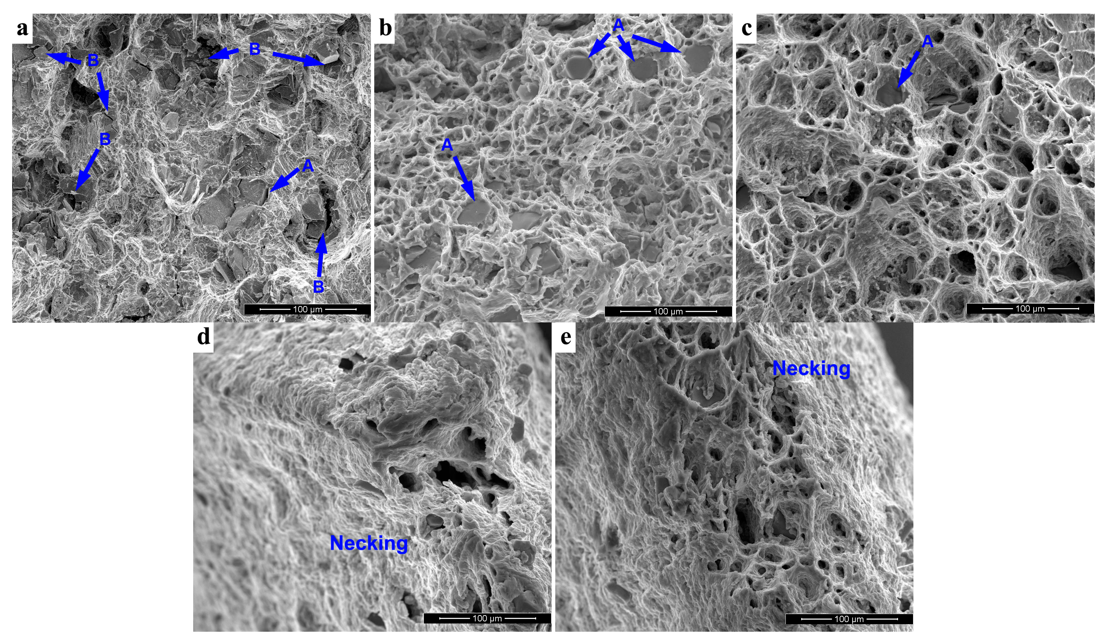
Figure 4.
Side view of fracture surfaces of the thixoforged composite tensile tested at different temperatures: (a) 25 °C; (b) 150 °C; (c) 200 °C; (d) 250 °C; (e) 300 °C.
Figure 4.
Side view of fracture surfaces of the thixoforged composite tensile tested at different temperatures: (a) 25 °C; (b) 150 °C; (c) 200 °C; (d) 250 °C; (e) 300 °C.

Figure 5.
SEM images showing Mg2Si particles: (a,b) fragmentation on fracture surface and side view of it at 25 °C; (c,d) fragmentation and interfacial debonding on the fracture surface at 150 °C; (e) showing eutectic Mg2Si particle in the side view of the fracture surface at 25 °C.
Figure 5.
SEM images showing Mg2Si particles: (a,b) fragmentation on fracture surface and side view of it at 25 °C; (c,d) fragmentation and interfacial debonding on the fracture surface at 150 °C; (e) showing eutectic Mg2Si particle in the side view of the fracture surface at 25 °C.
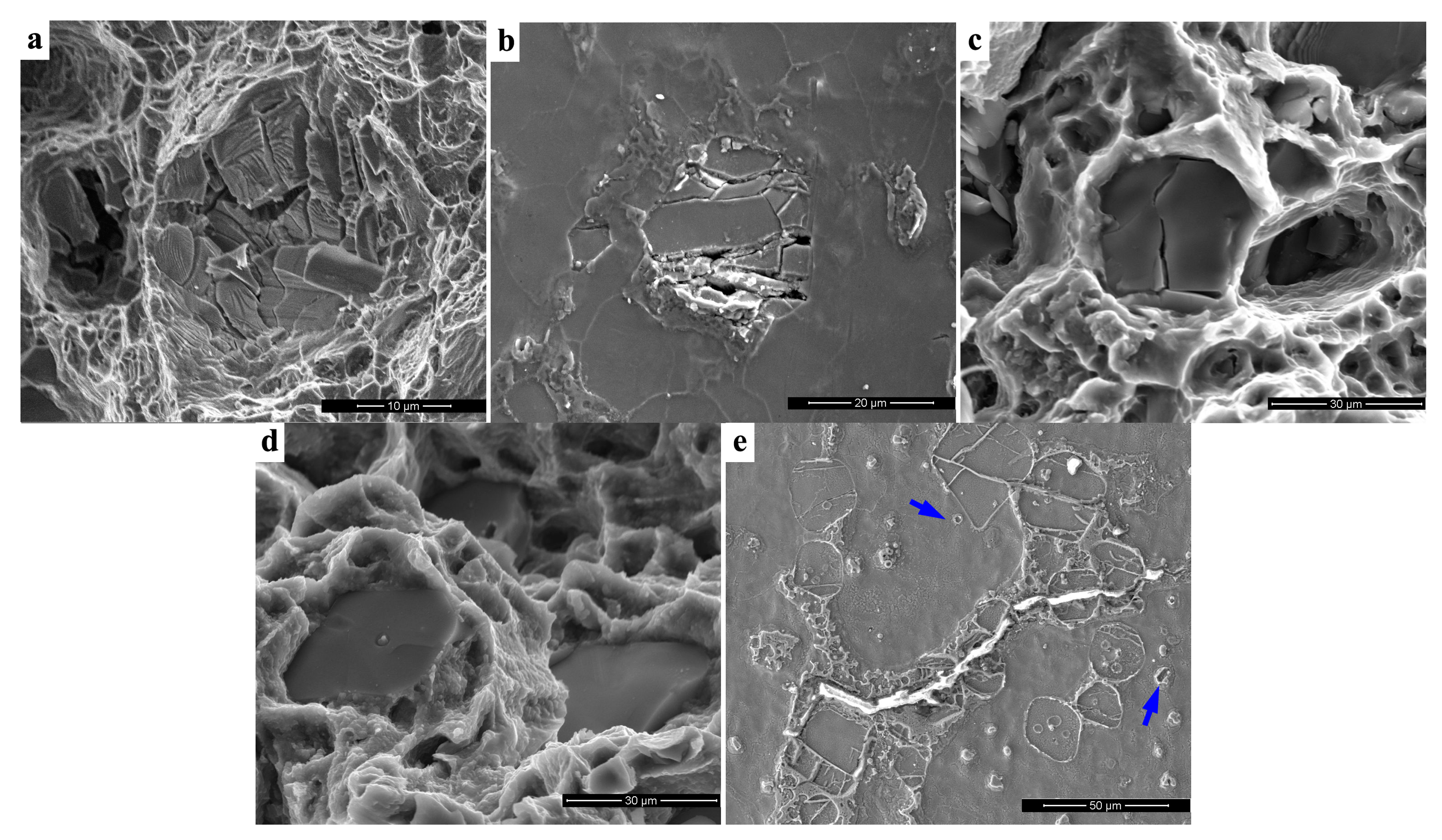
Figure 6.
The variations in tensile properties of the thixoforged composite tensile tested at 200 °C under different initial strain rates.
Figure 6.
The variations in tensile properties of the thixoforged composite tensile tested at 200 °C under different initial strain rates.

Figure 7.
Fracture surface of the thixoforged composite tensile tested at 200 °C under different initial strain rates: (a) 0.01 s−1; (b) 0.15 s−1; (c) 0.2 s−1.
Figure 7.
Fracture surface of the thixoforged composite tensile tested at 200 °C under different initial strain rates: (a) 0.01 s−1; (b) 0.15 s−1; (c) 0.2 s−1.
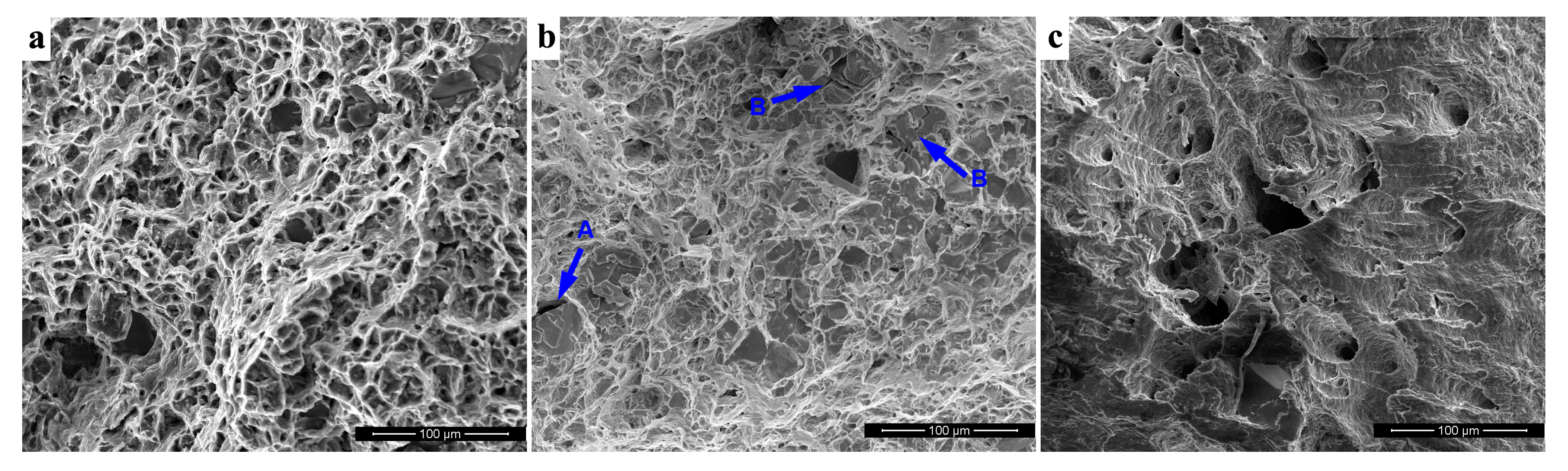
Figure 8.
Side view of fracture surface of the thixoforged composite tensile tested at 200 °C under different initial strain rates: (a) 0.01 s−1; (b) 0.15 s−1; (c) 0.2 s−1.
Figure 8.
Side view of fracture surface of the thixoforged composite tensile tested at 200 °C under different initial strain rates: (a) 0.01 s−1; (b) 0.15 s−1; (c) 0.2 s−1.
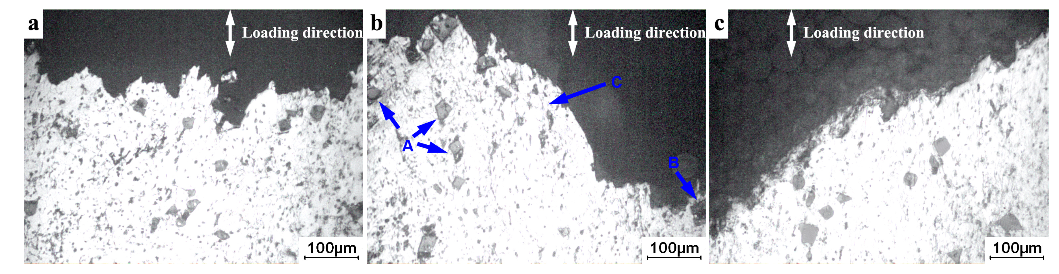
Figure 9.
Schematic of the fracture mechanism for the thixoforged composite tensile tested at 200 °C under the low and high initial strain rates.
Figure 9.
Schematic of the fracture mechanism for the thixoforged composite tensile tested at 200 °C under the low and high initial strain rates.

© 2018 by the authors. Licensee MDPI, Basel, Switzerland. This article is an open access article distributed under the terms and conditions of the Creative Commons Attribution (CC BY) license (http://creativecommons.org/licenses/by/4.0/).
Share and Cite
MDPI and ACS Style
Zhang, S.; Chen, T.; Zhou, J.; Xiu, D.; Li, T.; Cheng, K. Mechanical Properties of Thixoforged In Situ Mg2Sip/AM60B Composite at Elevated Temperatures. Metals 2018, 8, 106. https://doi.org/10.3390/met8020106
AMA Style
Zhang S, Chen T, Zhou J, Xiu D, Li T, Cheng K. Mechanical Properties of Thixoforged In Situ Mg2Sip/AM60B Composite at Elevated Temperatures. Metals. 2018; 8(2):106. https://doi.org/10.3390/met8020106
Chicago/Turabian StyleZhang, Suqing, Tijun Chen, Jixue Zhou, Dapeng Xiu, Tao Li, and Kaiming Cheng. 2018. "Mechanical Properties of Thixoforged In Situ Mg2Sip/AM60B Composite at Elevated Temperatures" Metals 8, no. 2: 106. https://doi.org/10.3390/met8020106
Note that from the first issue of 2016, this journal uses article numbers instead of page numbers. See further details here.