Article

Elastic and Plastic Behavior of the QE22 Magnesium Alloy Reinforced with Short Saffil Fibers and SiC Particles

1
Institute of Materials Science and Engineering, Faculty of Mechanical Engineering, Brno University of Technology, Technická 2896/2, 616 69 Brno, Czech Republic
2
Department of Physics of Materials, Faculty of Mathematics and Physics, Charles University, Ke Karlovu 5, 121 16 Praha 2, Czech Republic
3
CEITEC IPM, Institute of Physics of Materials, Academy of Sciences of the Czech Republic, v. v. i., Žižkova 22, 616 62 Brno, Czech Republic
*
Author to whom correspondence should be addressed.
Metals 2018, 8(2), 133; https://doi.org/10.3390/met8020133
Submission received: 30 December 2017 / Revised: 8 February 2018 / Accepted: 12 February 2018 / Published: 15 February 2018
(This article belongs to the Special Issue Metal Matrix Composites)

Abstract

:
Magnesium alloy QE22 (nominal composition 2 wt % Ag, 2 wt % mixture of rare earth elements, balance Mg) was reinforced with 5 vol % Saffil fibers and 15 vol % SiC particles. The hybrid composite was prepared via the squeeze cast technique. The microstructure of the monolithic alloy and composite was analyzed using scanning electron microscopy. Elastic modulus was measured at room temperature and modeled by the Halpin–Tsai–Kardos mathematical model. The strengthening effect of fibers and particles was calculated and compared with the experimentally obtained values. The main strengthening terms were determined. Fracture surfaces were studied via scanning electron microscope. While the fracture of the matrix alloy had a mainly intercrystalline character, the failure of the hybrid composite was transcrystalline.

1. Introduction

Cast magnesium alloys based on the Mg–Al–Zn–Mn system are designed for applications at ambient temperatures because the mechanical properties of these alloys rapidly deteriorate at elevated temperatures (above 120 °C) [1,2]. Among alloys for application at higher temperatures, the commercial QE22 is one of the most frequently used. Improvement in mechanical properties can be achieved using a proper thermal treatment [2] or, improving thermal stability as well, using various reinforcements that exhibit different mechanical and physical properties. Magnesium matrix composites show better wear resistance, enhanced strength, and creep resistance. Furthermore, they retain low density and good machinability [3,4]. Appropriate materials for the reinforcing phases are ceramics: oxides, nitrides, borides, carbides, carbon nanotubes (CNT), or intermetallic compounds [5,6,7,8,9,10,11]. The behavior of composites depends on the content, geometry, and physical and mechanical properties of the reinforcing phases. Metal matrix composites (MMCs) with long fibers, originally used to strengthen a plastic metallic composite matrix, exhibit several disadvantages, such as high anisotropy and low mechanical stability, since fibers are pulled out from the matrix under loading. Extremely high anisotropy is partially suppressed in composites reinforced with short fibers or whiskers [12,13,14,15,16,17]. This anisotropy may vanish in composites reinforced by particles [18]. On the other hand, mechanical properties of the particle-reinforced composites are inferior compared with fiber-reinforced composites. Using a combination of fibers and particles has proven to be a convenient compromise [19,20,21,22,23,24]. Reinforcing fibers/particles increases stiffness [25], improves mechanical and creep properties [19,20,21,22,23,24], and decreases the thermal expansion [26] of the composite. Nanocomposites with a reinforcing phase size of up to 100 nm have been intensively studied in the last decade [27,28,29,30,31]. Magnesium-alloy-based (nano)composites have been considered a material suitable for biomedical applications in the last few years [32]. Al2O3 ceramic Saffil fibers and SiC particles (SiCp) are commonly used reinforcements for Mg alloys. A combination of both materials, where Saffil fibers are replaced by cheaper SiC particles, may deliver a material with excellent strength, acceptable plasticity, improved creep properties, and enhanced wear resistance when compared to a mere fiber-reinforced composite with an Mg matrix. If composites are prepared via the hot extrusion technique, mechanical and physical properties are also influenced by the material texture [26]. Bonding between the metallic matrix and the reinforcing phase significantly affects the resulting properties of MMCs [33]. The presence of fibers/particles may also influence the precipitation processes in the metallic matrix during the composite preparation [34]. The chemical composition of magnesium alloys can be chosen according to the required mechanical properties of the composite matrix, considering the strengthening effect of the reinforcing particles/fibers. Rare earth element (RE) additions increase the strength of magnesium alloys at elevated temperatures and reduce weld cracking and casting porosity. The relatively weak tensile properties of Mg–RE–Zr alloys can be improved by an addition of Ag, which results in enhanced thermal treatment possibilities and age hardening processing of the alloy and final composite. QE22 is a widely used Mg–Ag cast alloy, where the content of silver below 2% allows for the formation of Mg–Nd precipitates similar to the Mg–RE alloys; the addition of silver also refines the precipitate size [2].
In this complex study, the elastic modulus and the plastic and fracture properties of the QE22 hybrid composite containing Saffil fibers and SiC particles were investigated with the aim to better understand the factors and processes influencing the resulting composite properties. In addition, the monolithic QE22 alloy was also studied in this work as a reference material.

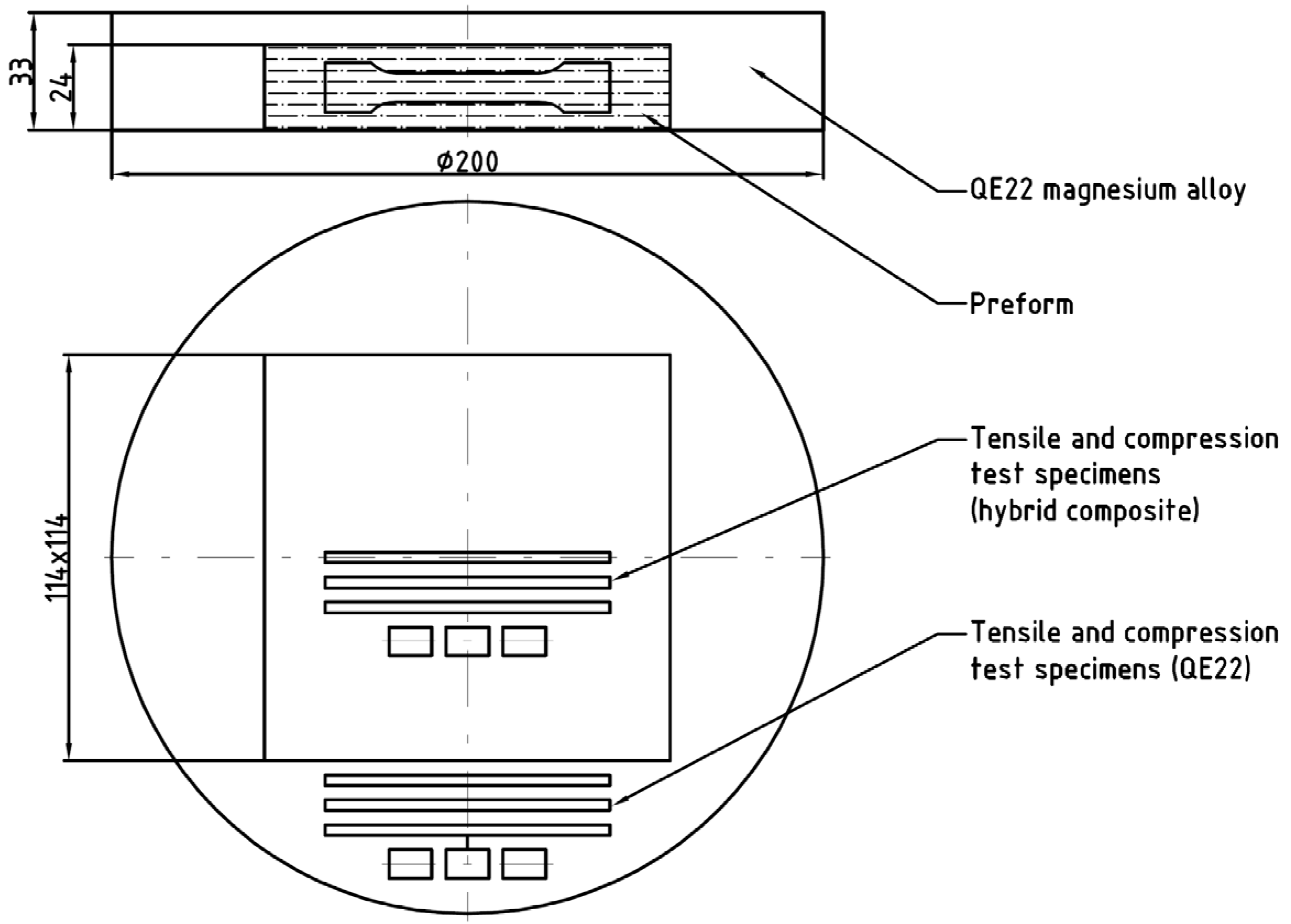
2. Experimental Material and Procedure

Commercially available cast QE22 magnesium alloy (nominal concentration in wt %: 2 Ag, 2 mischmetal mainly Nd-0.4 Zr, balance Mg) was used as the composite matrix material. The alloy was reinforced with 5 vol % Saffil® (97% δ-Al2O3, 3% SiO2) fibers and 15 vol % SiC particles using a preform consisting of fibers, particles, and a binder system (Al2O3 and starch). The orientation of fibers in the preform was planar, with a random orientation of fibers in the plane. Squeeze casting technology (ZFW, Clausthal-Zellerfeld, Germany) was used for the infiltration of liquid Mg alloy into the preform preheated to 1000 °C. Two-stage pressure of 80 and 150 MPa was applied in order to ensure that the resulting hybrid composite contains no pores. Saffil fibers exhibited a mean length of 78 ± 16 µm and were 3 µm in diameter (measured after squeeze casting). Nearly equiaxial SiC particles of an irregular shape were about 9 µm in size.
A scanning electron microscope (SEM) (ULTRA PLUS, Carl Zeiss GmbH, ‎Oberkochen, Germany) equipped with a dispersive X-ray spectrometer (EDS) (X-MAX, Oxford Instruments, Abingdon, England) was used for the microstructure characterization and analysis of the fracture surfaces of the prepared composite. An Everhar–Thornley-type secondary electron (SE) (Oxford Instruments, Abingdon, England) detector and a four-quadrant silicone back-scattered electron (BSE) (Oxford Instruments, Abingdon, England) detector were used to reveal material structural features. Geometry of the samples and the testing procedure corresponded to the EN ISO 6892-1 standard. Samples were not thermally treated preliminarily. Samples for deformation tests were cut from the cast ingot so that the stress axis was parallel to the fiber plane, as indicated in Figure 1. Flat specimens used for the tensile tests had an active length of 30 mm, a width of 8 mm, and a thickness of 3 mm. Cylindrical specimens for compression tests were prepared to have a diameter of 8 mm and a length of 12 mm. Before the compression tests, the grip heads of the testing machine were lubricated with MoS2. For both tensile and compression tests, three samples were used. Mechanical tests were carried out at room temperature (23 ± 2 °C) in a Zwick Z250 PC controlled testing device (Zwick GmbH & Co., Ulm, Germany) with a constant cross head speed of 1 mm⋅min−1, giving the strain rate of 5.5 × 10⁻⁴ s−1 (tension) and 1.4 × 10⁻³ s−1 (compression). True stress–true plastic strain curves were computed. Characteristic tensile/compression yield stress (TYS/CYS) and ultimate tensile/compression strength (UTS/UCS) were estimated together with the strain-to-fracture, εf.
The resonant frequency and damping analyzer RFDA HT650 (Integrated Material Control Engineering, Genk, Belgium) was used for the Young’s modulus measurements. Samples had a shape of bending beams (l = 23 mm, w = 3.6, t = 3.2 mm) with the longest axis either parallel (L-samples) or perpendicular (T-samples) to the fiber plane. Samples were mechanically excited into vibrations and the resonant frequency was determined. The Young’s moduli were calculated for both types of samples using the resonant frequencies.

3. Results and Discussion

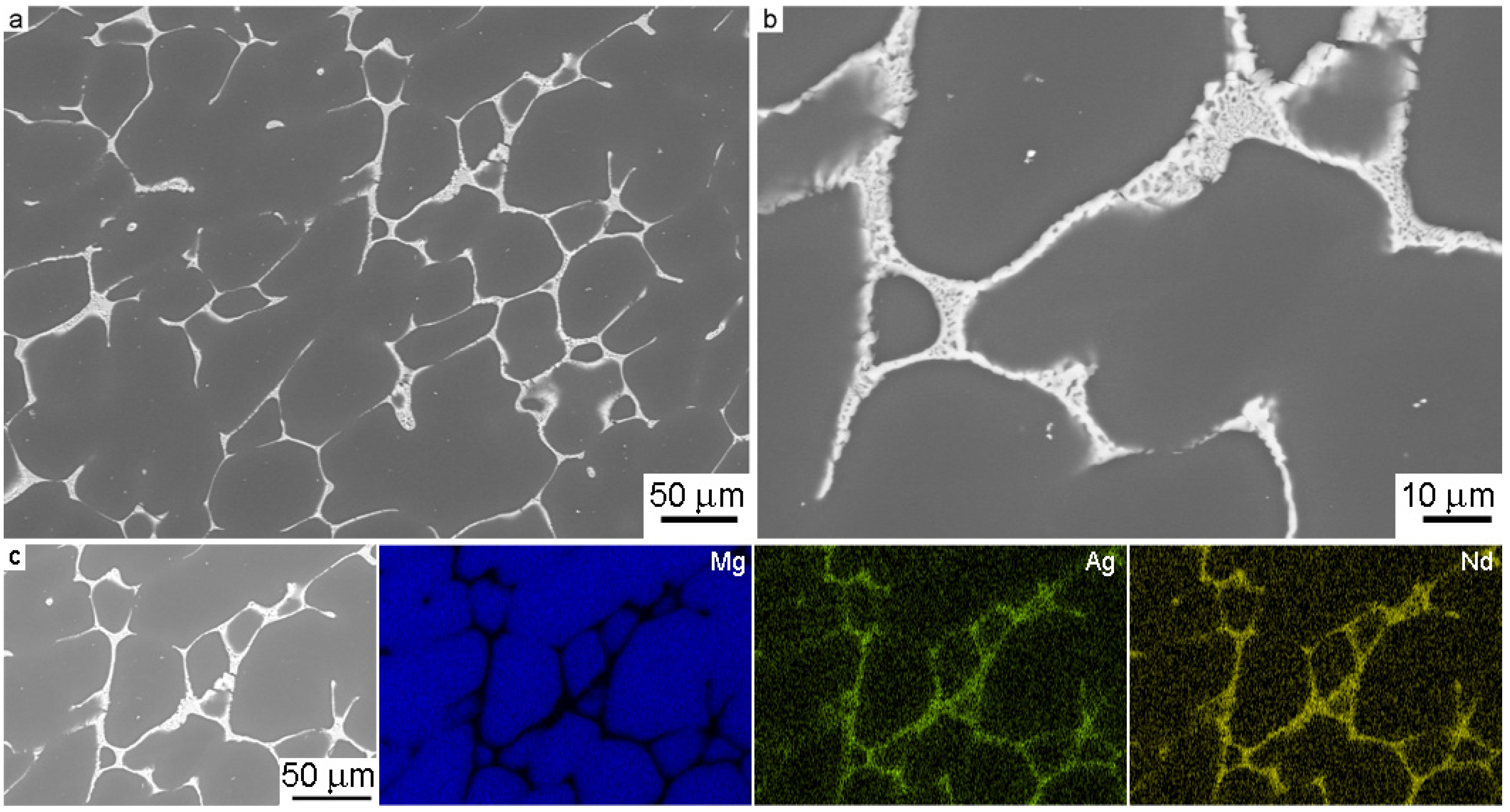
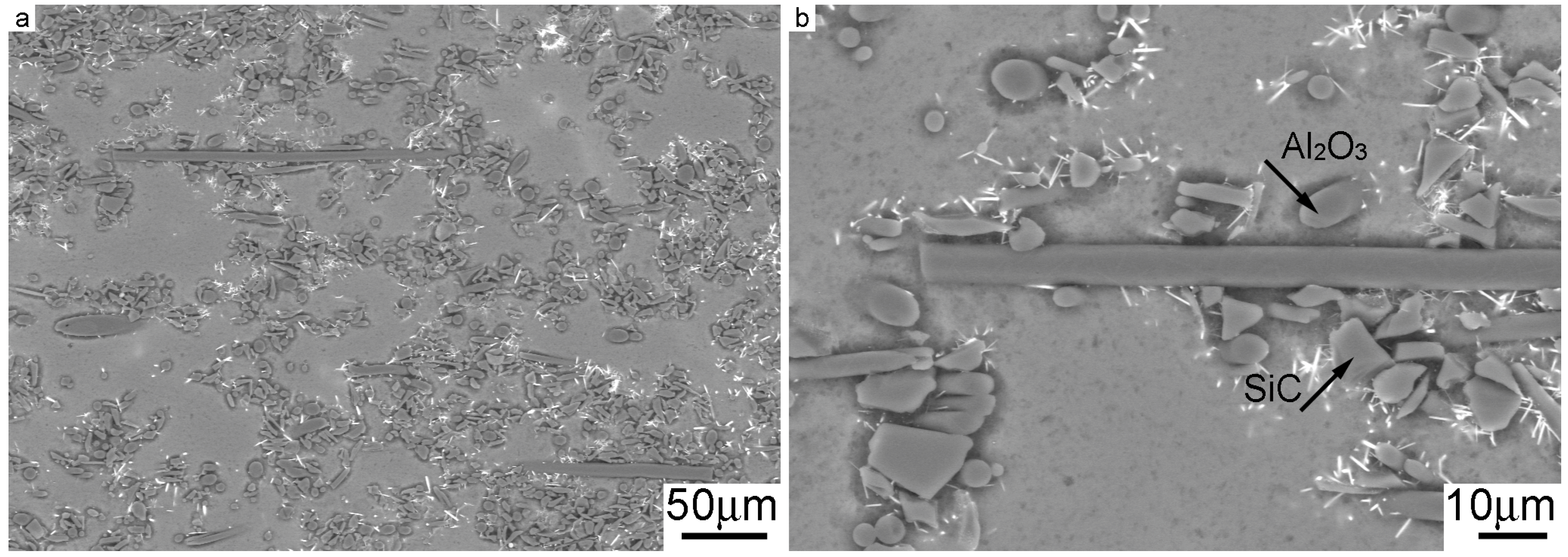
3.1. Microstructure Analysis

The QE22 magnesium alloy used in this study contained 2.59 wt % Ag and 1.47 wt % mischmetal (mainly Nd, with Pr, Ce, and La). The microstructure of the QE22 magnesium alloy shown in Figure 2a,b is composed of α grains consisting of a solid solution of alloying elements in Mg and precipitates situated at the grain boundaries. The elements analysis (EDS results) introduced in Figure 2c shows that particles at the grain boundaries are Mg3(Ag,RE) (63.6 wt % Mg, 17.9 wt % Ag, and 18.5 wt % RE) eutectics [22].
The microstructure of the hybrid composite is shown in Figure 3a,b. It is obvious that the distribution of SiC particles is not uniform; particles formed small clusters in the vicinity of fibers. Bright small needles visible in Figure 3 are the edges of dielectric SiC particles, which were charged with electrons during scanning. Kiehn et al. [34] found that the matrix in the QE22 alloy reinforced with Al2O3 fibers changed its chemical composition due to an increased content of Al introduced into the matrix from the inorganic binder in the preform. Al substitutes Ag in the precipitates which remains dissolved in the matrix. The grain size of the QE22 alloy was estimated to be (45.4 ± 0.8) µm and for the composite (6.2 ± 0.8) µm. The grain size was estimated using a linear intercept method from the light micrographs.

3.2. Elastic Properties

Unidirectionally continuous fiber-reinforced MMCs have shown a linear Young’s modulus increase with increasing fiber volume fraction in the fibers direction [11]. A Young’s modulus increase in the fibers direction is in agreement with the rule of mixtures, while a modulus increase in the transversal direction is very low. Particles in MMCs affect the modulus much less than predicted by the rule of mixtures. Experimentally determined Young’s modulus values for the hybrid L-sample, E H L ( e x ) = 74.5 GPa, and the T-sample, E H T ( e x ) = 71.2 GPa, are reported in Table 1. By comparing the experimental modulus values with the values obtained using the rule of mixtures ( E H R O M ), we can see that the measured moduli are substantially lower and exhibit certain anisotropy. The modulus measured on the L-sample is higher than that of the T-sample.
For material exhibiting certain anisotropy, the self-consistent Halpin–Tsai–Kardos model, originally developed for polymer composites, is more suitable [38,39]. Calculation of Young’s moduli for the hybrid composite samples according to the Halpin–Tsai–Kardos model can be divided into two steps. In the first step, the Young’s modulus, EC, of the fibers composite QE22 + 5 vol % Saffil (and for both orientations of the fiber plane) is calculated. The Young’s modulus of the hybrid composite, EH, with short fibers and SiC particles is computed in the second step. The modulus in the longitudinal direction (fiber plane is parallel to the longest sample axis) may be expressed as:
E C L = E m 1 + 2 L d η L ν f 1 η L ν f , η L = E f E m 1 E f E m + 2 L d
where Em is the modulus of the QE22 matrix alloy, Ef the modulus of the Saffil fibers, L the length, and d the diameter of the reinforcing fibers; νf is the volume fraction of the fibers. The transversal modulus (perpendicular to the fiber plane) can be determined as:
E C T = E m 1 + 2 η T ν f 1 η T ν f , η T = E f E m 1 E f E m + 2
Calculated values of both moduli, E C L (th) and E C T (th), are reported in Table 1 together with the experimentally obtained values of the matrix and Saffil moduli. Anisotropy of the material is reflected by different values calculated for longitudinal and transversal moduli. Calculated moduli, E C L (th) and E C T (th), were used for estimation of hybrid composite moduli according to following equations:
E H L = E C L 1 + A . B L ν p 1 B ν p , A = 7 5 ν p 8 10 ν p , B L = E p E C L E p + A . E C L
and
E H T = E C T 1 + A . B T ν p 1 B ν p , A = 7 5 ν p 8 10 ν p , B T = E p E C T E p + A . E C T
where Ep is the Young’s modulus of SiC particles, and νp their volume fraction.
By comparing the calculated moduli of the hybrid composite, E H L ( t h ) and E H T ( t h ) , with the experimentally obtained values, E H L ( e x ) and E H T ( e x ) , it is obvious that the agreement is much better than in the case of the rule of mixtures. The agreement of the measured values with the theoretical predictions is not ideal, because the real composite does not fully comply with the theoretical assumptions: fibers are not aligned in one direction (fibers have only planar isotropic distribution), particles are not regularly distributed in the matrix, and fiber length is not uniform. The model, however, depicts the experimentally observed composite anisotropy very well. Generally, it is possible to conclude that the transversal modulus, compared with the longitudinal modulus, is less influenced by the presence of reinforcing fibers. This result is in agreement with the results obtained on Al–Li composites reinforced with short fibers reported by Chawla [11].

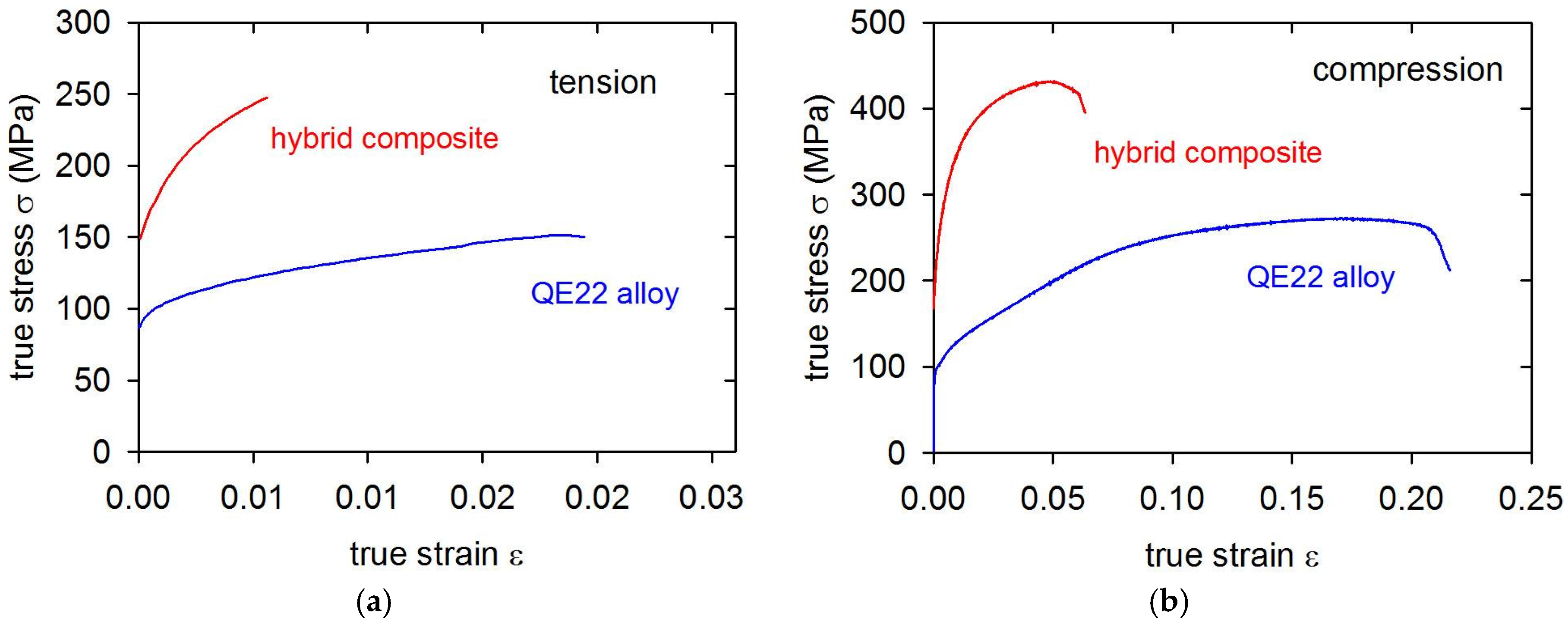
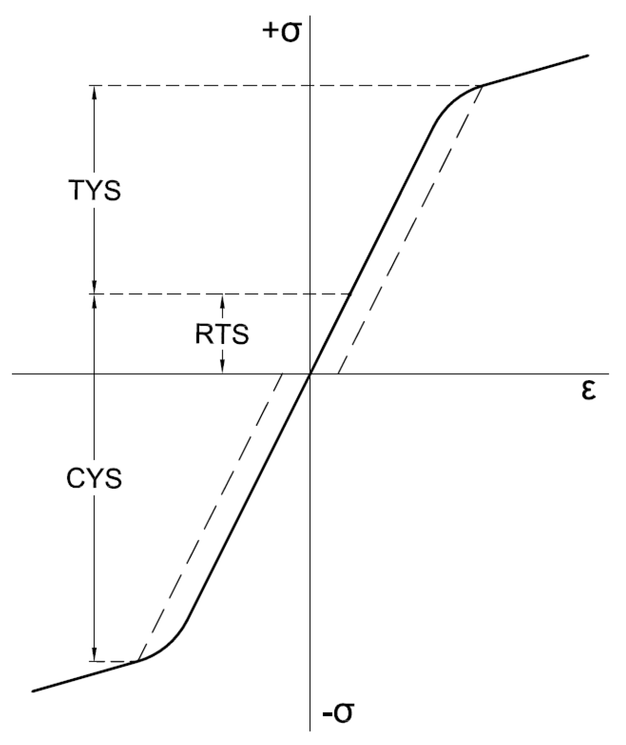
3.3. Plastic Deformation

True stress–true strain curves measured in tension for the monolithic QE22 alloy and hybrid composite are presented in Figure 4a. The tensile yield stress and the ultimate tensile strength values are reported in Table 2. A much greater amount of stress is necessary for the plastic deformation of the hybrid composite compared to the monolithic alloy. Furthermore, the work hardening coefficient θ = dσ/dε is higher for the composite.
True stress–strain curves obtained in the compression test are given in Figure 4b. Again, a big difference between the hybrid composite and the unreinforced alloy is clearly observed. Characteristic stresses estimated for both materials in compression are shown in Table 2, together with the plastic strain-to-fracture ratio, εf.
The plasticity of the alloy and the composite in tension was found to be very low, which is often observed in cast magnesium alloys [40]. Note also the anisotropy observed for both materials: the yield stress found in tension and compression are different. While the CYS estimated for the matrix alloy is lower than the TYS, the CYS in the hybrid composite is higher. These differences may be ascribed to the different deformation and strengthening mechanisms operating in the composite and the matrix alloy in tension and compression. The observed asymmetry of the TYS and CYS estimated for the matrix alloy is typical for magnesium alloys. Máthis et al. studied acoustic emission signals during the deformation of magnesium samples with different grain sizes. They found strong asymmetry in acoustic emission at temperatures lower than 200 °C corresponding to the activity of twin formation [41]. They concluded that different deformation mechanisms are active in tension and compression. While mainly dislocation glide facilitates plastic deformation in tension, mechanical twinning at the beginning of plastic deformation is the controlling mechanism in compression. This asymmetry depends also on the microstructure: it diminishes with increasing grain size. Twin boundaries that readily form during the compression test are impenetrable obstacles for dislocation motion. Therefore, twin formation contributes to an enhanced strain hardening of the material loaded in compression.
The presence of fibers or particles in a composite material influences the microstructure and straining via different mechanisms, which are summarized in Table 3. Usually, there is a large difference between the thermal expansion coefficient (CTE), α, of the metallic matrix and the ceramic reinforcement. The cooling down from manufacturing to room temperature generates thermal stresses in the composite. In this manner, the yield stress can be achieved in the matrix, and new thermal dislocation loops are punched [42]. Because of the incompatibility of the metallic matrix and the ceramic reinforcing phase, dislocations geometrically necessary are created during plastic deformation and contribute to the enhanced dislocation density [43]. The stress increase, ΔσD, due to increased density of thermal dislocations, 𝜌T, and dislocations geometrically necessary, 𝜌G, may be calculated using the known Taylor formula. The load transfer mechanism may be considered an important reinforcing mechanism. The stress increase due to load transfer, ΔσLT, was theoretically treated by several authors [44,45,46,47,48]. Nardone and Prewo [48] calculated the stress increase due to load transfer, σLT, for the aligned short fibers in the matrix, respecting the fact that fibers with the higher aspect ratio L/d contribute more to the composite strengthening; on the other hand, anisotropy of the material increases. Because not all fibers are oriented into the stress axis (but only the fiber plane) in the studied hybrid composite, it is necessary to calculate the load transfer component of the stress, β.ΔσLT, where β = 0.6 is the mean value of the direction cosines. For uniaxial particles, the load transfer value is ΔσLT = 0.5σmνp [49]. Discontinuously reinforced MMCs typically exhibit a finer grain structure compared with the unreinforced matrices [50]. The contribution of this refinement to the yield stress can be estimated using the Hall–Petch relationship [51]. Moreover, Orowan strengthening is also present as a result of the elastic behavior of dislocation segments passing stiff, closely spaced particles [52,53]. In MMCs, where distances between particles are of the order of µm, this mechanism usually plays only a marginal role. Newly created dislocations in the matrix partially accommodate thermal stresses. However, some tensile residual stresses remain in the matrix and either decrease (tension) or increase (compression) the stress necessary for plastic deformation [54].
Individual strengthening terms were calculated using constants introduced in Table 4 and are reported in Table 5.
In Table 5, YS (A) represents the yield stress of the unreinforced alloy, YS (M) is the yield stress in the matrix of the composite, and σtot is the calculated theoretical value for the hybrid composite yield stress. From Table 5, it is obvious that the main strengthening contributions in the hybrid composite are the load transfer, the increased dislocation density, and the small grain size of the composite matrix.
The load transfer term was obtained experimentally by Farkas et al. using neutron diffraction in situ measurements [61]. The authors found a load transfer value of about 100 MPa for the AX61 composite containing 26 vol % Saffil fibers. Taking into account the lower volume fraction of the strengthening fibers/particles and the lower strengthening contribution of particles to the load transfer, the calculated value ~30 MPa seems to be a good approximation of the load transfer real value for the studied composite. Mean residual stresses in the matrix were measured in magnesium-based MMCs by Farkas et al. ex situ [62] and in situ using neutron diffraction [61,63]. They found a higher <σm>max than that of the calculated estimation according to the equation reported in Table 3. In fact, in the first approximation, the difference between the TYS and CYS can be considered the residual thermal stress (RTS), as is schematically depicted in Figure 5. Difficulties with the appropriate combination of individual strengthening terms were solved by Lilhold [64] and Clyne and Whithers [65]. The stress contributions, which act more or less uniformly throughout the matrix, may be superimposed linearly. It follows from Table 5 that a simple sum of the strengthening terms gives a good approximation for the composite offset yield stresses.

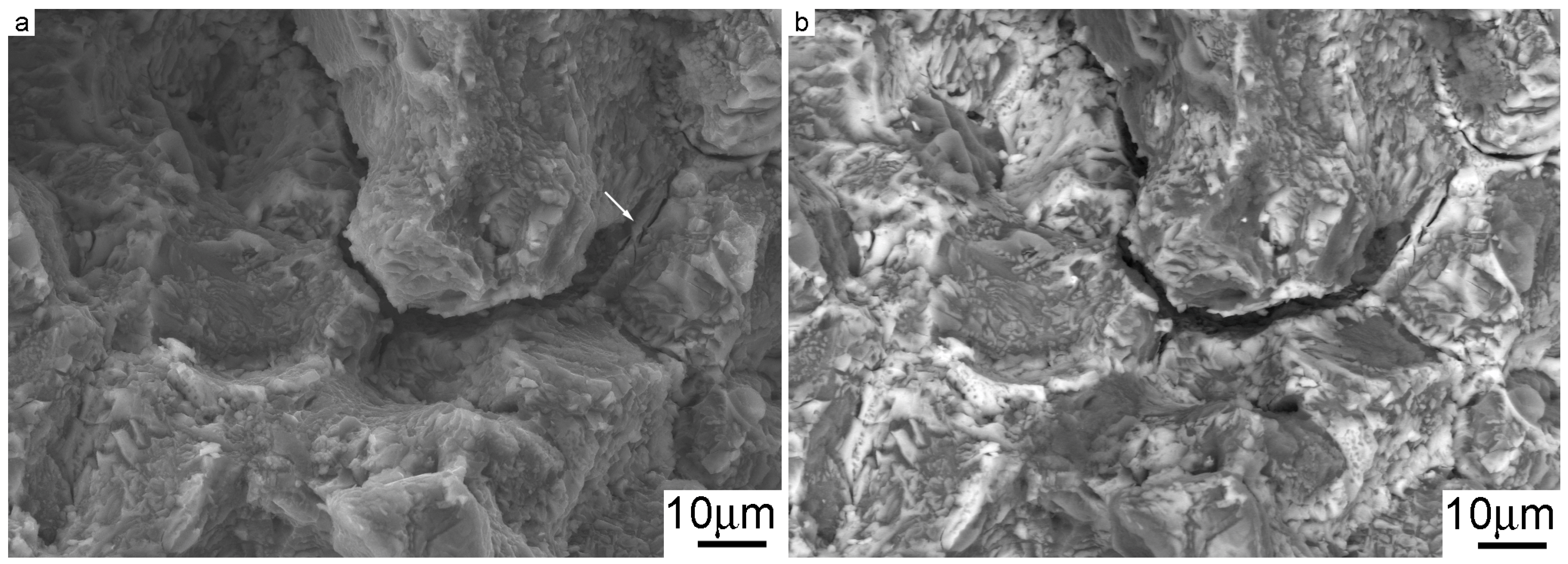
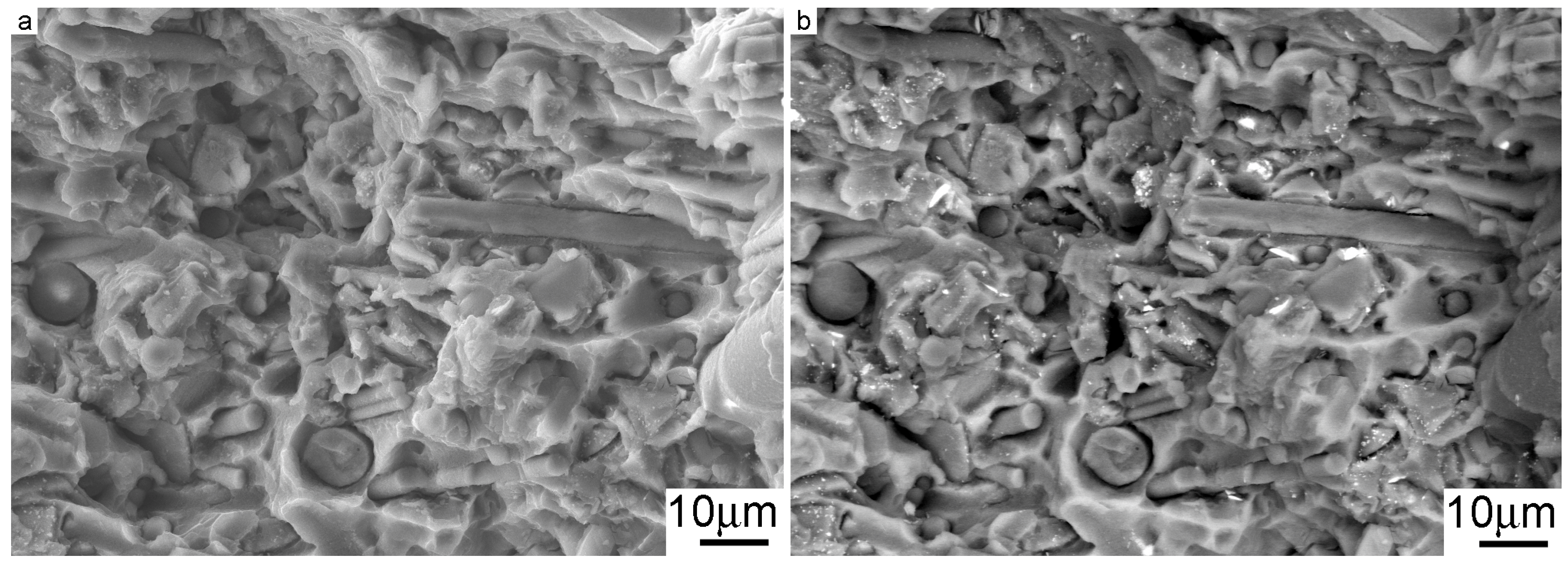
3.4. Fractographic Analysis

The fracture surface of the matrix alloy after the tensile test is shown in Figure 6a. The fracture mechanism is intercrystalline; the crack propagated along the grain boundaries. Eutectics situated at the grain boundaries in the naked crystal planes are more visible in Figure 6b (taken in back-scattered electron mode). Secondary cracks along the grain boundaries document that the eutectics present at the grain boundaries reduce their cohesive strength. Broken eutectic particles act as the crack initiation sites and the grain boundaries become a favorable path for the crack propagation. This is also the reason for the low ductility of this alloy. In Figure 6a, the twin boundary fracture is visible in several places. Twin boundary fracture is a typical failure mechanism in the QE22 magnesium alloy [66].
The scanning electron micrographs of the composite fracture surface are reported in Figure 7a,b. Uncovered fibers and particles are characteristically observed. A transcrystalline fracture mechanism can be seen in the case of the hybrid composite. Broken Saffil fibers and SiC particles are visible on the fracture surface shown in Figure 7. The bright needles discernible in the BSE representation are the edges of SiC particles charged in the microscope via the applied electron field. No pulling out of fibers and SiC particles from the matrix alloy due to applied tensile loading was observed on the composite fracture surface after the failure. This gives evidence of a strong bonding between the matrix alloy and the reinforcing fibers and particles. No traces of twinning were observed in the matrix areas of the fracture surface. A smaller grain size of the composite matrix reduces twinning [41], and only a transcrystalline fracture can take place. Besides reinforcement strengthening (presented in the form of increased dislocation density, a load transfer change, and Orowan strengthening), grain boundary strengthening (i.e., the Hall–Petch mechanism) was revealed by the hybrid composite’s fracture surface characteristics. The results of the fractographic analysis are, therefore, in agreement with the theoretically obtained results.

4. Conclusions

The elastic, plastic, and fracture properties of a MMC consisting of a QE22 magnesium alloy matrix reinforced with Saffil fibers and SiC particles were studied at room temperature. The following conclusions may be drawn based on the obtained results:
  • Young’s modulus measurements exhibited anisotropy owing to the 2D fiber distribution.
  • The Halpin–Tsai–Kardos self-consistent model was successfully used to model the Young’s modulus anisotropy, and the results are in good agreement with the experimentally obtained data.
  • The presence of reinforcing fibers and particles substantially increased both tensile and compression deformation flow stresses.
  • The ductility of the hybrid composite was radically decreased compared to the cast matrix alloy.
  • The load transfer, the increased dislocation density, and the Hall–Petch strengthening are the main reinforcing mechanisms in the case of studied hybrid composite.
  • Fracture of the matrix is mainly intercrystalline due to brittle eutectics present at the grain boundaries.
  • Fracture of the hybrid composite is transcrystalline; no pulling out of the reinforcing fibers or particles was observed.

Acknowledgments

This research was carried out under the project CEITEC 2020 (LQ1601) with financial support from the Ministry of Education, Youth and Sports of the Czech Republic under the National Sustainability Programme II. Work was also supported by the project NETME Centre Plus (Lo1202), a project of the Ministry of Education, Youth and Sports under the National Sustainability Programme. The research was conducted under IPMinfra, supported through Project No. LM2015069 of MEYS.

Author Contributions

Josef Zapletal, Zuzanka Trojanová, and Pavel Doležal conceived and designed the experiments; Josef Zapletal, Pavel Doležal, and Michal Knapek performed the experiments; Josef Zapletal, Zuzanka Trojanová, Pavel Doležal, and Michal Knapek analyzed the data; Zuzanka Trojanová, Josef Zapletal, and Pavel Doležal contributed reagents/materials/analysis tools; Zuzanka Trojanová and Stanislava Fintová wrote the paper.

Conflicts of Interest

The authors declare no conflict of interest. The founding sponsors had no role in the design of the study; in the collection, analyses, or interpretation of data; in the writing of the manuscript; or in the decision to publish the results.

References

  1. Polmear, I.J. Magnesium Alloys and Their Applications; Mordike, B.L., Hehmann, F., Eds.; DGM: Oberursel, Germany, 1992; p. 201. ISBN 978-3883551845. [Google Scholar]
  2. Advesian, M.M. ASM Speciality Handbook: Magnesium and Magnesium Alloys; Advesian, M.M., Baker, H., Eds.; ASM International: Russell Township, OH, USA, 1999; ISBN 978-0-87170-657-7. [Google Scholar]
  3. Kainer, K.U. Magnesium Alloys and Their Applications; Mordike, B.L., Hehmann, F., Eds.; DGM: Oberursel, Germany, 1992; p. 415. ISBN 978-3883551845. [Google Scholar]
  4. Oakley, R.; Cochrane, R.F.; Stevens, R. Recent developments in magnesium matrix composites. Key Eng. Mater. 1995, 104–107, 387–416. [Google Scholar] [CrossRef]
  5. Dey, A.; Pandey, K.M. Magnesium metal matrix composites—A review. Rev. Adv. Mater. Sci. 2015, 42, 58–67. [Google Scholar]
  6. Park, Y.; Cho, K.; Park, I.; Park, Y. Fabrication and mechanical properties of magnesium matrix composite reinforced with Si coated carbon nanotubes. Procedia Eng. 2011, 10, 1446–1450. [Google Scholar] [CrossRef]
  7. Jiang, Q.C.; Wang, H.Y.; Ma, B.X.; Wang, Y.; Zhao, F. Fabrication of B4C particulate reinforced magnesium matrix composite by powder metallurgy. J. Alloy. Compd. 2005, 386, 177–181. [Google Scholar] [CrossRef]
  8. Han, G.Q.; Shen, J.H.; Ye, X.X.; Chen, B.; Imai, H.; Kondoh, K.; Du, W.B. The influence of CNTs on the microstructure and ductility of CNT/Mg composites. Mater. Lett. 2016, 181, 300–304. [Google Scholar] [CrossRef]
  9. Han, B.C.; Dunand, D.Q. Microstructure and mechanical properties of magnesium containing high volume fractions of yttria dispersoids. Mater. Sci. Eng. A 2000, 277, 297–304. [Google Scholar] [CrossRef]
  10. Yu, W.; Zhao, H.; Hu, X. Anisotropic mechanical and physical properties in textured Ti2AlC reinforced AZ91D magnesium composite. J. Alloy. Compd. 2018, 732, 894–901. [Google Scholar] [CrossRef]
  11. Chawla, K.K. Materials Science and Technology; Cahn, R.W., Haasen, P., Kramer, E.J., Eds.; Wiley-VCH: Weinheim, Germany, 1993; Volume 13, pp. 121–182. [Google Scholar]
  12. Hassan, S.F.; Gupta, M. Development of high performance magnesium nano-composites using nano-Al2O3 as reinforcement. Mater. Sci. Eng. A 2005, 392, 163–168. [Google Scholar] [CrossRef]
  13. Trojanová, Z.; Gärtnerová, V.; Lukáč, P.; Drozd, Z. Mechanical properties of Mg alloys composites reinforced with short Saffil® fibres. J. Alloy. Compd. 2004, 378, 19–26. [Google Scholar] [CrossRef]
  14. Trojanová, Z.; Száraz, Z.; Lábár, J.; Lukáč, P. Deformation behaviour of an AS21 alloy reinforced by short Saffil fibres and SiC particles. J. Mater. Process. Technol. 2005, 162–163, 131–138. [Google Scholar] [CrossRef]
  15. Ho, K.F.; Gupta, M.; Srivatsan, T.S. The mechanical behavior of magnesium alloy AZ91 reinforced with fine copper particulates. Mater. Sci. Eng. A 2004, 369, 302–308. [Google Scholar] [CrossRef]
  16. Jayalakshmi, S.; Kailas, S.V.; Seshan, S. Tensile behaviour of squeeze cast AM100 magnesium alloy and its Al2O3 fibre reinforced composites. Compos. Part A 2002, 33, 1135–1140. [Google Scholar] [CrossRef]
  17. Trojanová, Z.; Drozd, Z.; Kúdela, S.; Száraz, Z.; Lukáč, P. Strengthening in Mg–Li matrix composites. Compos. Sci. Technol. 2009, 67, 1965–1973. [Google Scholar] [CrossRef]
  18. Manoharan, M.; Lim, S.C.V.; Gupta, M. Application of a model for the work hardening behavior to Mg/SiC composites synthesized using a fluxless casting proces. Mater. Sci. Eng. A 2002, 333, 243–249. [Google Scholar] [CrossRef]
  19. Zhang, X.; Zhang, Q.; Hu, H. Tensile behaviour and microstructure of magnesium AM60-based hybrid composite containing Al2O3 fibres and particles. Mater. Sci. Eng. A 2014, 607, 269–276. [Google Scholar] [CrossRef]
  20. Kumar, S.R.; Panigrahi, M.K.; Thakur, S.K.; Kainer, K.U.; Chakraborty, M.; Dhindaw, B.K. Characterization of stress in reinforcements in magnesium based squeeze infiltrated cast hybrid composites. Mater. Sci. Eng. A 2006, 415, 207–212. [Google Scholar] [CrossRef]
  21. Kumar, S.; Dieringa, H.; Kainer, K.U. Effect of particulate content on the thermal cycling behaviour of the magnesium alloy based hybrid composites. Compos. Part A 2005, 36, 321–325. [Google Scholar] [CrossRef]
  22. Svoboda, M.; Pahutová, M.; Kuchařová, K.; Sklenička, V.; Kainer, K.U. Microstructure and creep behaviour of magnesium hybrid composites. Mater. Sci. Eng. A 2007, 462, 220–224. [Google Scholar] [CrossRef]
  23. Arunachaleswaran, A.; Pereira, I.M.; Dieringa, H.; Huang, Y.; Hort, N.; Dhindaw, B.K.; Kainer, K.U. Creep behavior of AE42 based hybrid composites. Mater. Sci. Eng. A 2007, 460–461, 268–276. [Google Scholar] [CrossRef]
  24. Arunachaleswaran, A.; Dhindaw, B.K.; Dieringa, H.; Hort, N.; Kainer, K.U. Microstructure characterisation and creep properties of AE42 based hybrid composites prepared by squeeze casting process. Trans. Indian Inst. Met. 2007, 60, 87–91. [Google Scholar]
  25. Roy, S.; Gebert, J.-M.; Stasiuk, G.; Piat, R.; Weidenmann, K.A.; Wanner, A. Complete determination of elastic moduli of interpenetrating metal/ceramic composites using ultrasonic techniques and micromechanical modelling. Mater. Sci. Eng. A 2011, 528, 8226–8235. [Google Scholar] [CrossRef]
  26. Trojanová, Z.; Drozd, Z.; Minárik, P.; Lukáč, P.; Kasakewitsch, A. Influence of texture on the thermal expansion coefficient of Mg/BN nanocomposite. Thermochim. Acta 2016, 644, 69–75. [Google Scholar] [CrossRef]
  27. Penchal Reddy, M.; Shakoor, R.A.; Parande, G.; Manakari, V.; Ubaid, F.; Modamed, A.M.A.; Gupta, M. Enhanced performance of nano-sized SiC reinforced Al metal matrix nanocomposites synthesized through microwave sintering and hot extrusion techniques. Prog. Nat. Sci. 2017, 27, 606–614. [Google Scholar] [CrossRef]
  28. Chen, Y.; Tekumalla, S.; Guo, Y.B.; Shabadi, R.; Shim, V.P.W.; Gupta, M. The dynamic compressive response of a high-strength magnesium alloy and its nanocomposite. Mater. Sci. Eng. A 2017, 702, 65–72. [Google Scholar] [CrossRef]
  29. Gupta, M.; Wong, W.L.E. Magnesium-based nanocomposites: Lightweight materials of the future. Mater. Charact. 2015, 105, 30–46. [Google Scholar] [CrossRef]
  30. Casati, R.; Vedani, M. Metal Matrix Composites Reinforced by Nano-Particles—A Review. Metals 2014, 4, 65–83. [Google Scholar] [CrossRef]
  31. Jayakumar, J.; Raghunath, B.K.; Rao, T.H. Recent Development and Challenges in Synthesis of Magnesium Matrix Nano Composites—A Review. Int. J. Latest Res. Sci. Technol. 2012, 1, 164–171. [Google Scholar]
  32. Zhao, C.; Wu, H.; Ni, J.; Zhang, S.; Zhang, X. Development of PLA/Mg composite for orthopedic implant: Tunable degradation and enhanced mineralization. Compos. Sci. Technol. 2017, 147, 8–15. [Google Scholar] [CrossRef]
  33. Trojanová, Z.; Ferkel, H.; Lukáč, P.; Riehemann, W. Two new high-damping magnesium composites. Phys. Status Solidi 2002, 193, 205–210. [Google Scholar] [CrossRef]
  34. Kiehn, J.; Smola, B.; Vostrý, P.; Stulíková, I.; Kainer, K.U. Microstructure Changes in Isochronally Annealed Alumina Fibre Reinforced Mg-Ag-Nd-Zr Alloy. Phys. Status Solidi 1997, 164, 709–723. [Google Scholar] [CrossRef]
  35. Magnesium Elektron® QE22 Casting Alloy. Available online: http://www.matweb.com/search/datasheettext.aspx?matguid=05ed4d435e5648058e27e84284aaceae (accessed on 15 January 2018).
  36. Saffil—Specific Property Information. Available online: http://www.saffil.com/index/fibre_home/property_information.aspx (accessed on 15 January 2018).
  37. Property of Silicon Carbide (SiC). Available online: http://www.qualitymaterial.net/news_list85.html (accessed on 15 January 2018).
  38. Halpin, J.C. Effect of Environmental Factors on Composite Materials; Technical Report AFML-TR-67-423; US Air Force Material Laboratory: Dayton, OH, USA, 1969. [Google Scholar]
  39. Halpin, J.C.; Kardos, J.L. Halpin-Tsai equations: A review. Polym. Eng. Sci. 1976, 16, 344–352. [Google Scholar] [CrossRef]
  40. Mendelson, S. Dislocations Dissociations in hcp Metals. J. Appl. Phys. 1970, 41, 1893–1910. [Google Scholar] [CrossRef]
  41. Máthis, K.; Čapek, J.; Zdražilová, Z.; Trojanová, Z. Investigation of tension-compression asymmetry of magnesium by use of the acoustic emission technique. Mater. Sci. Eng. A 2011, 528, 5904–5907. [Google Scholar] [CrossRef]
  42. Arsenault, R.J.; Shi, N. Dislocation generation due to differences between the coefficients of thermal expansion. Mater. Sci. Eng. 1986, 81, 175–187. [Google Scholar] [CrossRef]
  43. Ashby, M.F. The deformation of plastically non-homogeneous materials. Philos. Mag. 1970, 21, 399–424. [Google Scholar] [CrossRef]
  44. Taya, M.; Arsenault, R.J. A comparison between a shear lag type model and an Eshelby type model in predicting the mechanical properties of a short fiber composite. Scr. Metall. 1987, 21, 349–354. [Google Scholar] [CrossRef]
  45. Ryu, H.J.; Cha, S.I.; Hong, S.H. Generalized shear-lag model for load transfer in SiC/Al metal-matrix composites. J. Mater. Res. 2003, 18, 2851–2858. [Google Scholar] [CrossRef]
  46. Zhang, C.Y.; Qiu, Y.P. Modified shear lag model for fibers and fillers with irregular cross-sectional shapes. J. Adhes. Sci. Technol. 2003, 17, 397–408. [Google Scholar] [CrossRef]
  47. Karbhari, V.M.; Wilkins, D.J. An “engineering” modification to the shear-lag model as applied to whisker and particulate reinforced composites. Scr. Metall. Mater. 1991, 25, 707–712. [Google Scholar] [CrossRef]
  48. Nardone, V.C.; Prewo, K.M. On the strength of discontinuous silicon carbide reinforced aluminum composites. Scr. Metall. 1986, 20, 43–48. [Google Scholar] [CrossRef]
  49. Aikin, R.M., Jr.; Christodoulou, L. The role of equiaxed particles on the yield stress of composites. Scr. Metall. Mater. 1991, 25, 9–14. [Google Scholar] [CrossRef]
  50. Arsenault, R.J.; Wang, L.; Feng, C.R. Strengthening of composites due to microstructural changes in the matrix. Acta Metall. Mater. 1991, 39, 47–57. [Google Scholar] [CrossRef]
  51. Armstrong, R.W. Theory of the Tensile Ductile-Brittle Behaviour of Polycrystalline h.c.p. Materials with Application to Beryllium. Acta Metall. 1986, 16, 347–355. [Google Scholar] [CrossRef]
  52. Scattergood, R.O.; Bacon, D.J. The Orowan mechanism in anisotropic crystals. Philos. Mag. A 1975, 31, 179–198. [Google Scholar] [CrossRef]
  53. Yeh, Y.-H.; Nakashima, H.; Kurishita, H.; Goto, S.; Yoshinaga, H. Absence of Threshold Stress for High-Temperature Creep of Dispersion- and Solution-Hardened Al-3.1 at % Mg-1.3 vol % be Alloy. Mater. Trans. 1990, 31, 778–785. [Google Scholar] [CrossRef]
  54. Delannay, F. Thermal Stresses and Thermal Expansion in MMCs. In Comprehensive Composite Materials; Clyne, T.W., Ed.; Elsevier: Amsterdam, The Netherlands, 2000; Volume 3, ISBN 978-0-08-042993-9. [Google Scholar]
  55. Pekguleryuz, M.O.; Kainer, K.U.; Kaya, A. (Eds.) Fundamentals of Magnesium Alloy Metallurgy, 1st ed.; Woodhead Publishing: Cambridge, UK, 2013; ISBN 9780857097293. [Google Scholar]
  56. Rudajevová, A.; Gärtnerová, V.; Jäger, A.; Lukáč, P. Influence of the thermal strain on the dilatation characteristics of Mg8Li and Mg10Li alloys. Kov. Mater. 2004, 42, 185–192. [Google Scholar]
  57. Lide, D.R. (Ed.) Handbook of Chemistry and Physics, 73rd ed.; CRC Press: Boca Raton, FL, USA, 1992; ISBN 978-0849304736. [Google Scholar]
  58. Ono, N.; Nakamura, K.; Miura, S. Influence of Grain Boundaries on Plastic Deformation in Pure Mg and AZ31 Mg Alloy Polycrystals. Mater. Sci. Forum 2003, 419–422, 195–200. [Google Scholar] [CrossRef]
  59. Lavrentev, F.F.; Pokhil, Y.A. Relation of dislocation density in different slip systems to work-hardening parameters for magnesium crystals. Mater. Sci. Eng. 1975, 18, 261–270. [Google Scholar] [CrossRef]
  60. Cáceres, C.H.; Lukáč, P. Strain hardening behaviour and the Taylor factor of pure magnesium. Philos. Mag. 2008, 88, 977–989. [Google Scholar] [CrossRef]
  61. Farkas, G.; Trojanová, Z.; Száraz, Z.; Minárik, P.; Máthis, K. Effect of the fiber orientation on the deformation mechanisms of magnesium-alloy based fiber reinforced composite. Mater. Sci. Eng. A 2015, 643, 25–31. [Google Scholar] [CrossRef]
  62. Trojanová, Z.; Farkas, G.; Máthis, K.; Lukáč, P. Hardening and softening in an AJ51 magnesium alloy reinforced with Saffil fibres. In Magnesium Technology 2014; Alderman, M., Manuel, M.V., Hort, N., Neelameggham, N.R., Eds.; TMS (The Mineral, Metals and Materials Society): Pittsburgh, PA, USA, 2014; pp. 435–440. ISBN 9781118888162. [Google Scholar]
  63. Farkas, G.; Choe, H.; Máthis, K.; Száraz, Z.; Noh, Y.; Trojanová, Z.; Minárik, P. In situ investigation of deformation mechanisms in magnesium-based metal matrix composites. Met. Mater. Int. 2015, 21, 652–658. [Google Scholar] [CrossRef]
  64. Lilholt, H. Additive strengthening. In Deformation of Multi-Phase and Particle Containing Materials, Proceedings of the 4th Risø International Symposium on Metallurgy and Materials Science, Risø, Roskilde, Denmark, 5–9 September 1983; Bilde-Sørensen, J.B., Hansen, N., Horsewell, A., Leffers, T., Lilholt, H., Eds.; Risø National Laboratory: Roskilde, Denmark, 1983; pp. 381–392. [Google Scholar]
  65. Clyne, T.W.; Whithers, P.J. An Introduction to Metal Matrix Composites; Cambridge University Press: Cambridge, UK, 1993; ISBN 9780511623080. [Google Scholar]
  66. Khan, F.; Panigradi, S.K. Age hardening, fracture behavior and mechanical properties of QE22 Mg alloy. J. Magnes. Alloy. 2015, 3, 210–217. [Google Scholar] [CrossRef]
Figure 1. Sample positions in the casting.
Metals 08 00133 g001
Figure 2. Back-scattered electron (BSE) scanning electron micrograph of the QE22 alloy (a); a closer view of the precipitates (b); the distribution of main alloying elements in the alloy determined by EDS (c).
Metals 08 00133 g002
Figure 3. The microstructure (BSE mode) of the hybrid composite (a); a closer view of a fiber surrounded by SiC particles (b).
Metals 08 00133 g003
Figure 4. True stress–true strain curves of the QE22 matrix alloy and the hybrid composite in tension (a) and compression (b).
Metals 08 00133 g004
Figure 5. Schematic explanation of the composite tension–compression anisotropy.
Metals 08 00133 g005
Figure 6. Scanning electron micrograph of the alloy fracture surface after the tensile test (a) the same location taken in BSE mode (b).
Metals 08 00133 g006
Figure 7. Fracture surface of the hybrid composite after straining in the tension test (a); the same location taken in BSE mode (b).
Metals 08 00133 g007
Table 1. Experimental moduli values of the matrix (Em), fibers (ESaffil), particles (ESiC), hybrid L-sample E H L ( e x ) , and hybrid T-sample E H T ( e x ) . Calculated moduli values for Mg + Saffil in the L direction E C L ( t h ) , Mg + Saffil in the T direction E C T ( t h ) , and theoretical values of the hybrid moduli in both directions, E H L ( t h ) and E H T ( t h ) , data from [35,36,37].
EmESaffilESiC E C L ( t h ) E C T ( t h ) E H L ( t h ) E H T ( t h ) E H L ( e x ) E H T ( e x ) EH(ROM)
GPaGPaGPaGPaGPaGPaGPaGPaGPaGPa
44.130041061.4248.676.561.574.571.1118.5
[35][36][37]-------
Table 2. Characteristic stresses and the strain-to-fracture ratio obtained in tension and compression.
MaterialTYSCYSUTSUCSεfεf
MPaMPaMPaMPaTensionCompression
QE22 alloy108.3100.5151.4260.30.020.22
composite207.6243.4247.3431.40.0060.06
Table 3. Individual contributions to strengthening following from the presence of the reinforcing phase.
MechanismEquationSymbols
Increased dislocation density due to thermal strain ΔαΔT ρ T = B ν f , p Δ α Δ T b ( 1 ν f , p ) 1 t b Burgers vector of dislocations,
B = 12 (p) B = 10 (f),
t minimum size of (f) or (p)
Dislocation geometrically necessary ρ G = ν f , p 8 ε p b t εp plastic strain, νf,p volume fraction of fibers/particles
Enhanced dislocation density Δ σ D = α 1 m G b ( ρ T + ρ G ) 1 / 2 α1 constant, m Taylor factor, G shear modulus
Load transfer Δ σ L T = σ L T σ m = σ m ν f ( L + d ) ( L d ) 4 L L fibers length,
d fibers diameter
Hall–Petch strengthening Δ σ G S = K y ( d 2 1 / 2 d 1 1 / 2 ) d1, d2 grain sizes,
Ky Hall–Petch constant
Orowan strengthening Δ σ O R = G b Λ + 5 2 π G ν f , p ε p Λ distance between particles or fibers ends
Residual thermal stresses σ m max = 2 3 σ m ln ( 1 ν f , p ) ν f , p 1 ν f , p σm yield stress in matrix
Table 4. Constants used for calculations of the strengthening terms, data from [55,56,57,58,59,60].
α (QE22)α (Saffil)α (SiC)Ky (Mg)α1Gbm
K−1K−1K−1MPa⋅mm1/2-GPam-
26 × 10−66 × 10−66.6 × 10−6100.35173.2 × 10−104.5
[55][56][57][58][59]--[60]
Table 5. Individual contributions to strengthening of the hybrid composite.
Deformation
Mode
YS (A)YS (M)ΔσLTΔσDΔσORΔσGSm>maxσtotYS (ex)
MPaMPaMPaMPaMPaMPaMPaMPaMPa
tension108.3144.229.2 + 10.835.9225.2-202.4207.6
compresion100.5136.427.6 +10.235.9225.226.9229.3243.4

