Article

Roller Burnishing of Particle Reinforced Aluminium Matrix Composites

Professorship Micromanufacturing Technology, Chemnitz University of Technology, Reichenhainer Str. 70, 09126 Chemnitz, Germany
*
Author to whom correspondence should be addressed.
Metals 2018, 8(2), 95; https://doi.org/10.3390/met8020095
Submission received: 15 December 2017 / Revised: 17 January 2018 / Accepted: 22 January 2018 / Published: 27 January 2018

Abstract

:
Energy and resource efficient systems often demand the use of light-weight materials with a specific combination of properties. However, these requirements usually cannot be achieved with homogeneous materials. Consequently, composites enabling tailored properties gain more and more importance. A special kind of these materials is aluminium matrix composites (AMCs), which offer elevated strength and wear resistance in comparison to the matrix alloy. However, machining of these materials involves high tool wear and surface imperfections. An approach to producing high-quality surfaces consists in roller burnishing of AMCs. Furthermore, such forming technologies allow for the generation of strong compressive residual stresses. The investigations address the surface properties in the roller burnishing of AMCs by applying different contact forces and feeds. For the experiments, specimens of the alloy AA2124 reinforced with 25% volume proportion of SiC particles are used. Because of the high hardness of the ceramic particles, roller bodies were manufactured from cemented carbide. The results show that roller burnishing enables the generation of smooth surfaces with strong compressive residual stresses in the matrix alloy. The lowest surface roughness values are achieved with the smallest feed (0.05 mm) and the highest contact force (750 N) tested. Such surfaces are supposed to be beneficial for components exposed to dynamic loads.

1. Introduction

Aluminium matrix composites are lightweight materials consisting of an aluminium alloy and at least one reinforcing component. Depending on the type of reinforcement they can be classified into:
  • Continuous fibre-reinforced AMCs.
  • Whisker-reinforced or short fibre-reinforced AMCs.
  • Particle-reinforced AMCs.
  • Hybrid AMCs with different types of reinforcement.
The type, proportion, and kind of reinforcements significantly influence the properties of such composites. In the majority of cases, an increase of the strength, the Young’s modulus, and the wear resistance is aimed for. Consequently, most of AMCs are particle reinforced. Typical particle reinforcements are silicon carbide and aluminium oxide, but titanium diboride, boron carbide, titanium aluminide, or titanium dioxide can also be used [1]. The fabrication is realised by casting processes (e.g., stir casting, squeeze casting, in-situ-casting, spray casting, infiltration), powder metallurgy routes, friction stir processing [2], or selective laser melting [3].
Aluminium matrix composites exhibit a high potential for tribological applications, for example brake discs, brake drums, and cylinder working surfaces of combustion engines. However, there are abrasive and adhesive wear mechanisms depending on the applied load and the properties of the tribological system. An increase of the particle proportion can significantly reduce the wear rate [4]. This can be referred to the behaviour of the ceramic particles acting as load-bearing components. Furthermore, the contact area between the AMC part and the counterpart is markedly reduced [2]. However, the surface structure of the friction partners strongly affects the mechanisms of action in tribological systems.
In general, the surface properties of components influence the functional behaviour of technical systems significantly. In addition to the material, the manufacturing processes are a key factor for the surface integrity. Especially, a mechanical surface modification exhibits a very high potential for a customised improvement of the performance, resulting from changes in the surface structure and the surface layer. There are three basic effects that are involved in mechanical surface modification processes [5]:
  • A plastic deformation of the roughness peaks can result in a smoothing effect.
  • The forces acting parallel and perpendicular to the surface lead, in combination with a plastic deformation of the surface, to a stretched area with maximum strains at the surface.
  • A Hertzian pressure yields to a maximum deformation below the surface.
These effects often involve a decrease of the surface roughness values, work hardening, strong compressive residual stresses, and a grain refinement in the surface layer. Consequently, appropriate mechanical modifications of the surface contribute to an enhancement of the fatigue properties, corrosion resistance, tribological behaviour, and wear resistance.
However, there are many different technologies for a mechanical surface modification, which can be subdivided in burnishing, shot peening, and machine hammer peening processes. The surface properties depend strongly on the specific process parameters and can be varied in a large range.
AlMangour and Yang [6] investigated the surface quality and the mechanical properties after shot peening of stainless steel. The results showed a significant reduction of the surface roughness values. Furthermore, the properties of the surface layer could be modified markedly. The crystalline grain size was approximately halved, but the micro-strain and the absolute values of the compressive residual stresses could be increased considerably. The modified surface properties led to a reduction of the wear volume loss in tribomechanical tests.
However, Scheel et al. [7] studied the influence of different mechanical processes on a modification of the surface. For high strength aluminium alloys, a burnishing process led to stronger and deeper residual stresses compared to shot peening. Consequently, specimens modified by a burnishing process performed better in high cycle fatigue tests in comparison to untreated and shot peened specimens respectively.
For a surface modification of rotationally symmetric components, burnishing processes are preferred because of the simple integration in lathes. Many research studies deal with the burnishing of different alloys, but there is only little information about burnishing of aluminium materials.
El-Axir et al. [8] studied the ball burnishing of the alloy 2014, using a hardened steel ball with a diameter of 8 mm. The surface roughness values could be reduced markedly. For a higher burnishing speed and a burnishing feed in the range of 0.15 mm to 0.25 mm, the smallest surface roughness values were achieved. Moreover, for low speeds multiple burnishing passes should be applied, yet for higher speeds surface deterioration occurs after repeated burnishing.
El-Tayeb et al. [9] investigated the ball burnishing of the alloy 6061 with hardened steel balls. The results show an important influence of the burnishing force and the burnishing speed on the surface roughness. For optimal parameters, an arithmetic mean surface roughness Ra of 0.09 µm was achieved.
Nestler and Schubert [10] studied the influence of the machining parameters in diamond smoothing of aluminium matrix composites (AMCs). This process is characterised by a sliding relative movement of the diamond body and the workpiece instead of a primarily rolling relative movement of the roller body and the workpiece. The surface roughness values could be reduced markedly by diamond smoothing, especially for the smallest feed applied. In this case, mean surface roughness values after smoothing were about 0.04 µm for Ra and 0.7 µm for Rz using a diamond body with a spherical radius of 2 mm. Furthermore, residual stresses in the matrix alloy of about −400 MPa could be gained. The speed varied did not show any significant influence on the surface properties.
However, there are no studies in roller burnishing of heterogeneous materials like aluminium matrix composites, although they gain more and more in importance. Consequently, appropriate parameters for roller burnishing of particle-reinforced AMCs have to be found. The focus of the research is on the surface structure and the residual stress state. Both aspects can influence the functional behaviour, especially fatigue properties or corrosion resistance, markedly.

2. Materials and Methods

For the experiments an aluminium matrix composite consisting of the alloy AA2124 and SiC particles with a volume proportion of 25% was used. The AMC is produced by a powder metallurgy route comprising a high energy mixing process and subsequent hot isostatic pressing for powder consolidation. Afterwards, the billets are extruded to bars applying an extrusion ratio of about 50:1. For an increase of the material strength, the bars are heat treated to the condition T4 (solution annealed, quenched and naturally aged). Figure 1 shows the microstructure of the material in the longitudinal direction.
The mean particle size lies in the range of 2 µm to 3 µm. However, there are many smaller and some larger particles, too. The cross-section polish for the longitudinal direction reveals a slight banding, resulting from the extrusion process. Table 1 represents the mechanical properties of the material identified for the longitudinal direction (hardness excluded).
The finally premachined specimens for the investigations in roller burnishing exhibit a diameter of 23 mm and a length of 20 mm. Both faces are chamfered with an angle of 45° and a size of 1 mm. For clamping, one face of each specimen comprises a blind hole with a diameter of 8 mm, and on the opposite side there is a small centre hole. The values for the surface roughness depth Rz before roller burnishing were in the range of about 5 µm to 7 µm.
The experiments were carried out on a precision lathe of the type SPINNER PD 32 (SPINNER Werkzeugmaschinen GmbH, Sauerlach, Germany). A clamping of the specimens with a mandrel allowed machining the complete cylindrical length. Because of the high forces in roller burnishing, for this process clamping was supported by an additional live centre on the opposite side. The turning tools for premachining were carried by the disc turret (BARUFFALDI S.p.a., Tribiano (MI), Italy). Because of the highly abrasive effect of the hard ceramic particles CVD (chemical vapour deposition), diamond tipped indexable inserts were used. The turning tools exhibit a polished rake face and a very sharp cutting edge with a rounding of about 3 µm. For final premachining, an insert of the type VCGW 110304 (DTS GmbH – Diamond Tooling Systems, Kaiserslautern, Germany) screwed on a tool holder of the kind SVVCN 1212 F11 (WNT Deutschland GmbH, Kempten, Germany) was applied. Final premachining was realised with a feed of f = 0.14 mm, a cutting speed of vc = 150 m/min, and a depth of cut of ap = 0.25 mm.
For burnishing, a discoid roller body with a radius of 21 mm in the rolling direction and a radius of 2 mm perpendicular to the rolling direction was used. The roller body consists of cemented carbide to withstand the hard ceramic particles in the AMC. The burnishing tool (BAUBLIES AG, Renningen-Malmsheim, Germany) was mounted on a three-axis force dynamometer of the type Kistler 9257A (Kistler Instrumente AG, Winterthur, Switzerland) to monitor the rolling force. This force can be varied by a change of the helical compression spring, its pretension, and the infeed. The tool was adjusted to an angle of 90° between the direction of the burnishing force and the feed direction, which corresponds to the axial direction of the specimens.
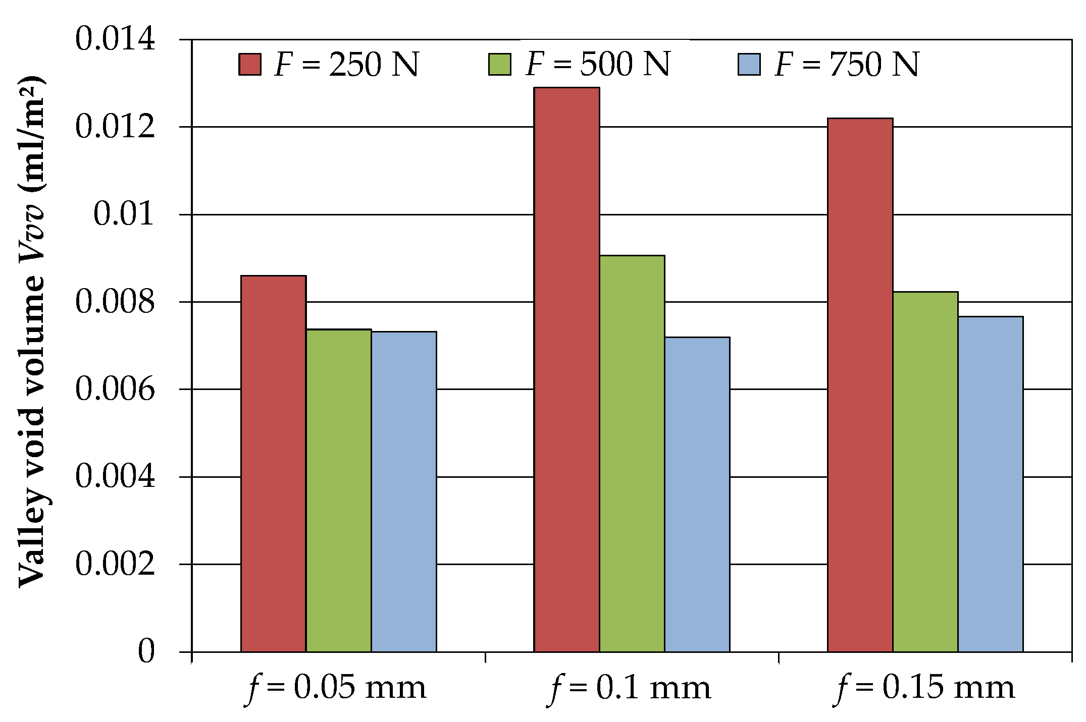
For all experiments, the rolling speed was kept constant at 150 m/min. The final rolling force was adjusted by the infeed amounting to about 0.2 mm. The feed was varied in the range of 0.05 mm to 0.15 mm and the rolling force from 250 N to 750 N using a full factorial design for these both parameters. For each combination of parameters tested, three specimens were machined to assess the process stability. The process parameters for roller burnishing are presented in Table 2. An emulsion cooling with a concentration of approximately 5% was used to reduce the tendency for adhesion of the aluminium based material on the indexable inserts and the roller body.
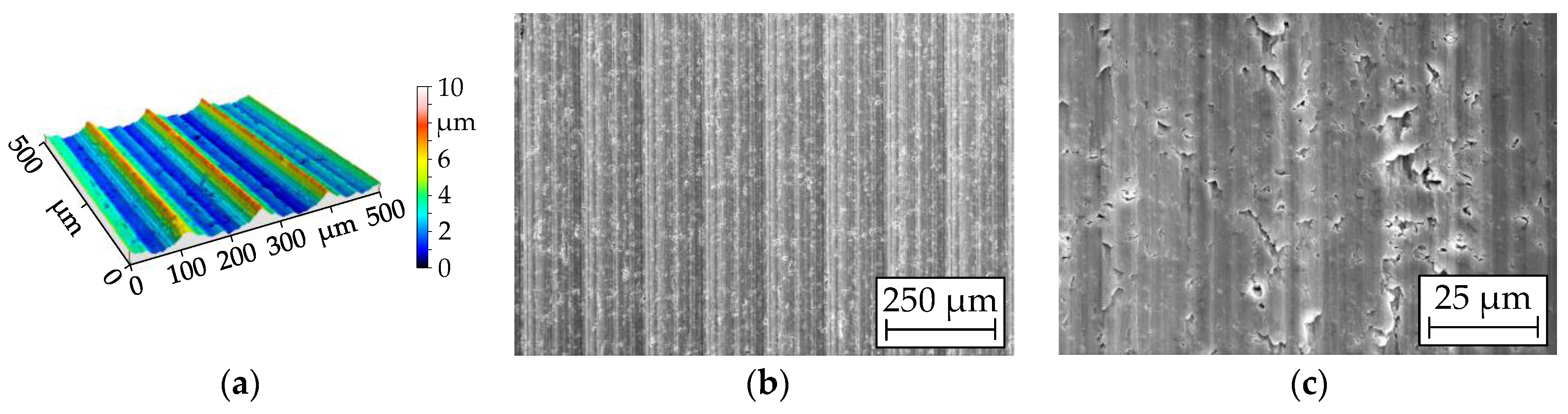
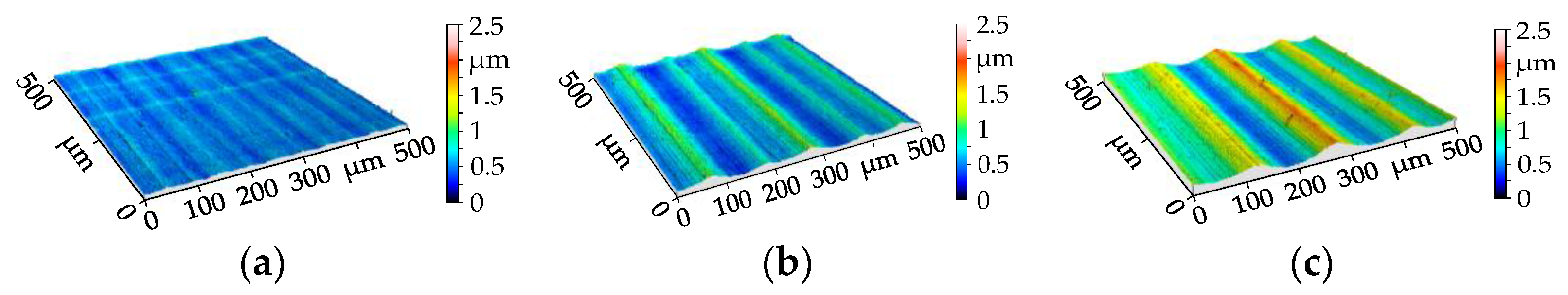
The surface roughness in the axial direction was measured using a stylus instrument of the type Mahr LD 120 (Mahr GmbH, Göttingen, Germany). The measuring length is 4 mm and filtering of the profile is done in accordance to ISO 11562. Because of the comparatively strong influence of surface imperfections on the roughness values, each specimen was measured thrice at different positions. Additionally, for each parameter combination tested, one three-dimensional surface profile was generated with the same measurement equipment including a supplemental cross table. For these measurements, the distance of the measuring points is 1 µm for the circumferential and the axial direction. The measuring field has a size of 2 mm in the axial direction and 0.5 mm in the circumferential direction. For a detailed examination of the surfaces, the 3D profiles were leveled by the subtraction method. Afterwards, a form removal was done by applying a fifth degree polynomial filter (Digital Surf, Besançon, France). These data were used for detailed 3D images of the surface structure, representing a smaller area than measured. A characterisation of the porosity of the surfaces generated by roller burnishing requires further mathematical procedures. After using a robust Gaussian filter with a cut-off wavelength of 0.08 mm, a line by line leveling followed to remove the kinematic roughness.
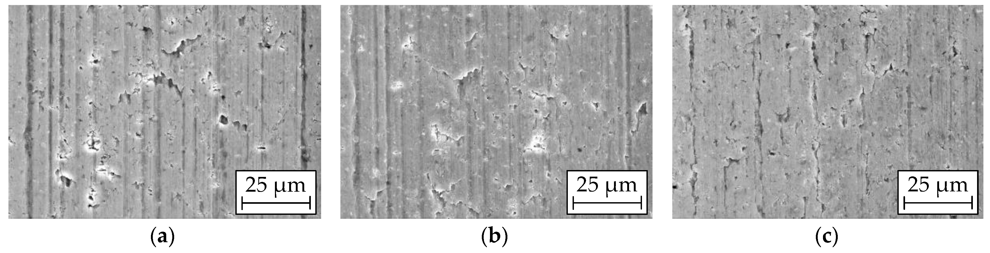
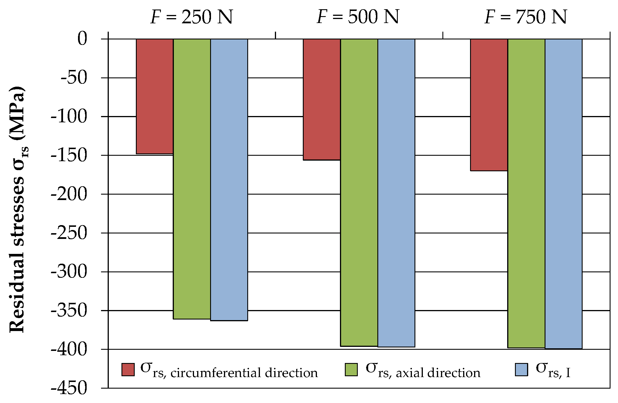
Furthermore, SEM (scanning electron microscope) micrographs (Carl Zeiss AG, Oberkochen, Germany) of the specimens’ surfaces were obtained using a Zeiss LEO 1455VP microscope to characterise the surface structure and the imperfections. The residual stresses in the surface layer were determined by X-ray diffraction analysis performed with a Siemens D5000 diffractometer (Siemens Aktiengesellschaft, Munich, Germany). The measurements were done with a cobalt anode in the lattice planes {420} of the aluminium alloy using sin² ψ method. Thereby, an area with a diameter of about 2 mm was detected.

3. Results and Discussion

3.1. Influence of the Feed and the Rolling Force on the Surface Structure

A detailed understanding of the rolling process and a profound discussion of the results require ample information about the structure of the premachined surface. Figure 2 presents details of the surface structure of a premachined specimen.
The three-dimensional surface profile shows distinct feed marks with a distance to each other, corresponding to the turning feed of 0.14 mm. Furthermore, form deviations of the arc-shaped tool corner and cutting edge chipping are reflected in this profile. A SEM micrograph with an overview section (Figure 2b) confirms the feed marks. Additionally, numerous voids with different sizes and shapes are revealed by a SEM micrograph with a larger magnification (Figure 2c).
The feed in roller burnishing has a significant influence on the surface structure. Figure 3 represents 3D surface profiles for a rolling force of 500 N.
Surfaces generated with a rolling feed of 0.05 mm are comparatively smooth and do not exhibit a distinct “waviness”. This can be explained by the very small theoretical roughness, represented in Figure 4 and Figure 5. For an increase of the feed, a kinematic roughness is regularly formed on the surface. The distance of the “single wave structures” complies with the rolling feed. However, there is an alternation of a higher and a lower “wave”. This may be due to small form deviations of the roller body. For the geometrical dimensions applied, one revolution of the roller body requires about two revolutions of the specimen, which underpins this assumption.
The most common parameters for the characterisation of the surface structure are the arithmetic mean surface roughness Ra and the surface roughness depth Rz. Figure 4 shows the influence of the feed and the rolling force on the arithmetic mean surface roughness.
The error bars represent the scattering of the values starting at the lowest values and ending at the highest value. Each coloured bar incorporates nine measurements (three measurements on each specimen at different locations). The white bars indicate the calculated values using the equation:
R a t h e o r f 2 31.2 r
The variable r stands for the radius of the roller body measured in the feed direction. For the smallest feed applied, the measured values are in the same range, but higher than the calculated value. This can be attributed to minor surface imperfections, especially voids and grooves. However, an increase of the feed results suggests the increasing influence of the rolling force. For lower forces, the measured values are smaller than the theoretical values. This is due to the stress state in roller burnishing, characterised by a high hydrostatic proportion. However, only deviatoric stresses contribute to the forming process. For higher feeds, the deviatoric stresses were not sufficient to form the theoretical roughness profile completely. It can be concluded that an increase of the rolling force involves a better forming of the theoretical roughness profile and consequently higher values for the arithmetic mean surface roughness, especially for higher feeds.
However, there are some differences for the surface roughness depth, illustrated in Figure 5.
The determination of the error bars is in accordance with Figure 4. For a feed of 0.05 mm, the measured values are significantly higher than the theoretical value calculated with the equation
R z t h e o r f 2 8 r
This can be ascribed to surface imperfections, which have a stronger influence on the surface roughness depth than on the Ra-values. For the smallest force, the roughness profiles reveal deep voids increasing the roughness values. With an increase of the force the number and the depth of the voids decrease, resulting in smaller mean values and lower scattering. A reduction of the surface porosity requires strong compressive stresses in the stress deviator. This is supported by an enlargement of the rolling force. For an increase of the feed, the formation of the kinematic roughness profile gains in importance compared to the surface imperfections. This leads, for a feed of 0.15 mm, to measured surface roughness values Rz in the range of the theoretical value. Consequently, there is an increase of the surface roughness depth with a raising feed, which complies with the Ra-values. The surface roughness values for Ra and Rz lie in the same range like the values after diamond smoothing of AMCs [10].
The valley void volume is used as a measure for the porosity of the surfaces generated by roller burnishing. Figure 6 shows the influence of the feed and the rolling force on the valley void volume.
There is no significant effect of the feed on the valley void volume except for the lowest force applied. For all feeds tested, the rolling force of 250 N results in higher values for the valley void volume. This indicates that the smallest force is not sufficient for a prevention of the formation of voids or its closure. It is evidenced in particular for the feeds 0.1 mm and 0.15 mm, resulting in the highest values. However, an increase of the rolling force leads to a reduction of the valley void volume. This is confirmed by SEM micrographs (Figure 7) and can be referred to stronger compressive stresses in the stress deviator.
Surfaces generated with a rolling force of 250 N exhibit comparatively large and deep voids (Figure 7a). Furthermore, slight grinding grooves of the roller body are transferred to the surface of the specimens running in the circumferential direction. For an increase of the rolling force, the compressive stresses in the stress deviator become stronger. Consequently, the area and the depth of the voids decrease.

3.2. Influence of Roller Burnishing on the Residual Stresses

An evaluation of the residual stresses after roller burnishing requires information about the residual stress state of the premachined specimens. The X-ray diffraction analysis of a premachined specimen showed residual stresses of about −32 MPa in the axial direction and −95 MPa in the circumferential direction, both for the aluminium alloy. The roller burnishing process generally resulted in a significant increase of the absolute values of the residual stresses. However, for the feeds applied only small differences concerning the residual stress state of the burnished surface occurred. Figure 8 represents the results for a feed of 0.15 mm.
The red bars represent the residual stresses in the circumferential direction and the green bars the residual stresses in the axial direction. The first principle residual stresses (blue bars) approximately comply with the residual stresses in the axial direction. Consequently, the first principle axis has nearly the same direction as the rotational axis of the specimens. This can be attributed to the strongest compression of the surface area in the axial direction, resulting from the kinematic roughness of the premachined specimens. The diagram shows, for a feed of 0.15 mm and an increasing force, a slight growth of the absolute values of the residual stresses. This may be due to a decrease of the porosity of the surfaces, characterised by the valley void volume. The absolute values of the residual stresses in the axial direction correspond nearly to the yield strength of the matrix alloy and are significantly higher than the absolute values of the residual stresses in the circumferential direction. The reason for this is the stronger reduction of the surface size of the premachined specimens, exhibiting a kinematic roughness in the axial direction, to a nearly smooth cylindrical surface. The residual stresses in the axial direction correspond to the values measured on the surface of burnished AA2024-T351 [7].

4. Conclusions

Based on experimental investigations in roller burnishing of particle-reinforced aluminium matrix composites and detailed surface analyses the subsequent conclusions can be drawn.
  • Roller burnishing of aluminium matrix composites leads to a significant decrease of the surface roughness values. The lowest surface roughness value for Ra is about 0.05 µm.
  • For a feed larger than 0.05 mm, the surface structure exhibits a kinematic roughness corresponding to the calculated roughness values.
  • The roller burnishing process results in strong compressive residual stresses in the aluminium matrix. The absolute values of the residual stresses in the axial direction are much higher than the absolute values of the residual stresses in the circumferential direction.
  • The results in roller burnishing concerning roughness and residual stress state at the surface are comparable to the findings for diamond smoothing.
  • The modification of the surface properties is expected to improve the wear and the fatigue behaviour.
  • Further investigations have to be done to characterise the changes in the microstructure and to analyse the residual stresses in the subsurface area.

Acknowledgments

The authors gratefully acknowledge funding by the German Research Foundation (Deutsche Forschungsgemeinschaft, DFG) within the framework of the Collaborative Research Center SFB 692.

Author Contributions

Andreas Nestler and Andreas Schubert conceived and designed the experiments; Andreas Nestler performed the experiments, analysed the data, and wrote the paper.

Conflicts of Interest

The authors declare no conflict of interest.

References

  1. Ranjith, R.; Giridharan, P.K.; Kumar, G.S.; Seenivasan, N. A review on advancements in aluminium matrix composites. Int. J. Adv. Eng. Techol. 2016, VII, 173–176. [Google Scholar]
  2. Shojaeefard, M.H.; Akbari, M.; Asadi, P.; Khalkhali, A. The effect of reinforcement type on the microstructure, mechanical properties, and wear resistance of A356 matrix composites produced by FSP. Int. J. Adv. Manuf. Technol. 2017, 91, 1391–1407. [Google Scholar] [CrossRef]
  3. AlMangour, B.; Grzesiak, D.; Yang, J.-M. Selective laser melting of TiC reinforced 316L stainless steel matrix nanocomposites: Influence of starting TiC particle size and volume content. Mater. Des. 2016, 104, 141–151. [Google Scholar] [CrossRef]
  4. Prasat, S.V.; Ram, A.S.; Sivaprakash, S.; Suresh, K. A review on mechanical and wear behaviour of aluminium metal matrix composites. Int. Res. J. Eng. Technol. 2017, 4, 1261–1265. [Google Scholar]
  5. Schulze, V.; Bleicher, F.; Groche, P.; Gou, Y.B.; Pyun, Y.S. Surface modification by machine hammer peening and burnishing. Cirp. Ann. Manuf. Technol. 2016, 65, 809–832. [Google Scholar] [CrossRef]
  6. AlMangour, B.; Yang, J.-M. Improving the surface quality and mechanical properties by shot peening of 17-4 stainless steel fabricated by additive manufacturing. Mater. Des. 2016, 110, 914–924. [Google Scholar] [CrossRef]
  7. Scheel, J.; Prevéy, P.; Hornbach, D. Safe Life Conversion of Aircraft Aluminum Structures via Low Plasticity Burnishing for Mitigation of Corrosion Related Failures. In Proceedings of the Department of Defense Corrosion Conference, Washington, DC, USA, 10–14 August 2009. [Google Scholar]
  8. El-Axir, M.H.; Othman, O.M.; Abodiena, A.M. Study on the inner surface finishing of aluminum alloy 2014 by ball burnishing process. J. Mater. Process. Technol. 2008, 202, 435–442. [Google Scholar] [CrossRef]
  9. El-Tayeb, N.S.M.; Low, K.O.; Brevern, P.V. On the surface and tribological characteristics of burnishes cylindrical Al-6061. Tribol. Int. 2009, 42, 320–326. [Google Scholar] [CrossRef]
  10. Nestler, A.; Schubert, A. Effect of machining parameters on surface properties in slide diamond burnishing of aluminium matrix composites. Mater. Today Proc. 2015, 2S, S156–S161. [Google Scholar] [CrossRef]
Figure 1. SEM (scanning electron microscope) micrographs of the microstructure of the aluminium matrix composite in the longitudinal direction: (a) SE (secondary electrons) mode; (b) QBSD (quadrant backscatter electron detector).
Metals 08 00095 g001
Figure 2. Surface structure of a premachined specimen (ap = 0.25 mm, f = 0.14 mm, vc = 150 m/min): (a) 3D surface profile; (b) SEM micrograph (SEM magnification 100); (c) SEM micrograph (SEM magnification 1000).
Metals 08 00095 g002
Figure 3. Influence of the rolling feed on the surface structure (F = 500 N): (a) f = 0.05 mm; (b) f = 0.1 mm; (c) f = 0.15 mm.
Metals 08 00095 g003
Figure 4. Influence of the feed and the rolling force on the arithmetic mean surface roughness.
Metals 08 00095 g004
Figure 5. Influence of the feed and the rolling force on the surface roughness depth.
Metals 08 00095 g005
Figure 6. Influence of the feed and the rolling force on the valley void volume.
Metals 08 00095 g006
Figure 7. SEM micrographs of details of the surfaces generated with f = 0.15 mm: (a) F = 250 N; (b) F = 500 N; (c) F = 750 N.
Metals 08 00095 g007
Figure 8. Influence of the rolling force on the residual stresses for a feed of 0.15 mm.
Metals 08 00095 g008
Table 1. Mechanical properties of the aluminium matrix composite with standard deviations out of three tests (for the hardness out of five tests).
ParameterCharacteristic Value
Yield strength Rp0.2513 MPa ± 5 MPa
Ultimate tensile strength Rm699 MPa ± 8 MPa
Young’s modulus E117 GPa
Elongation without reduction of area Ag4.6% ± 1.0%
Vickers hardness HV219 HV10 ± 14 HV10
Table 2. Parameters for roller burnishing.
Process ParameterValues
Rolling force F250 N; 500 N; 750 N
Rolling feed f0.05 mm; 0.1 mm; 0.15 mm
Rolling speed v150 m/min

