Article

Microstructural Evolution during Severe Plastic Deformation by Gradation Extrusion

1
Institute of Materials Science and Engineering, Chemnitz University of Technology, D-09107 Chemnitz, Germany
2
Fraunhofer Institute for Machine Tools and Forming Technology, D-09126 Chemnitz, Germany
*
Author to whom correspondence should be addressed.
Metals 2018, 8(2), 96; https://doi.org/10.3390/met8020096
Submission received: 21 December 2017 / Revised: 22 January 2018 / Accepted: 24 January 2018 / Published: 27 January 2018

Abstract

:
In this contribution, we study the microstructural evolution of an age-hardenable AA6082 aluminum alloy during severe plastic deformation by gradation extrusion. A novel die design allowing an interruption of processing and nondestructive billet removal was developed. A systematic study on the microstructure gradient at different points of a single billet could be performed with the help of this die. Distinct gradients were investigated using microhardness measurements and electron microscopy. Our results highlight that gradation extrusion is a powerful method to produce graded materials with partially ultrafine-grained microstructures. From the point of view of obtaining an ultrafine-grained surface layer with maximum hardness, only a small number of forming elements is needed. It was also found that large incremental deformation by too many forming elements may result in locally heterogeneous microstructures and failure near the billet surface caused by localization of deformation. Furthermore, considering economical aspects of processing, fewer forming elements are preferred since several processing parameter-related cost factors are then significantly lower.

1. Introduction

Severe Plastic Deformation (SPD) processes are efficient techniques to increase a material’s strength by strain hardening and grain refinement [1,2]. Many studies have been focused on the most prominent SPD processes like equal-channel angular pressing (ECAP) [3,4,5,6], accumulative roll-bonding (ARB) [7], and high-pressure torsion (HPT) [8,9]. One of the main goals of most SPD processes is the introduction of large strains into the billet, typically with the aim of a homogeneous distribution [10,11,12,13]. In order to reduce microstructural gradients and to homogenize the billet’s properties, many SPD methods make use of repeated deformation steps [14,15,16,17] until a certain homogenization of the microstructure, as well as the corresponding mechanical properties, is achieved. Multiple passes of ECAP, for example, are often used to produce homogeneous bulk ultrafine-grained materials [18,19]. Much research has been performed in order to find optimum processing routes for multi-pass ECAP with enhanced grain refinement rates and maximum homogeneity [20,21,22].
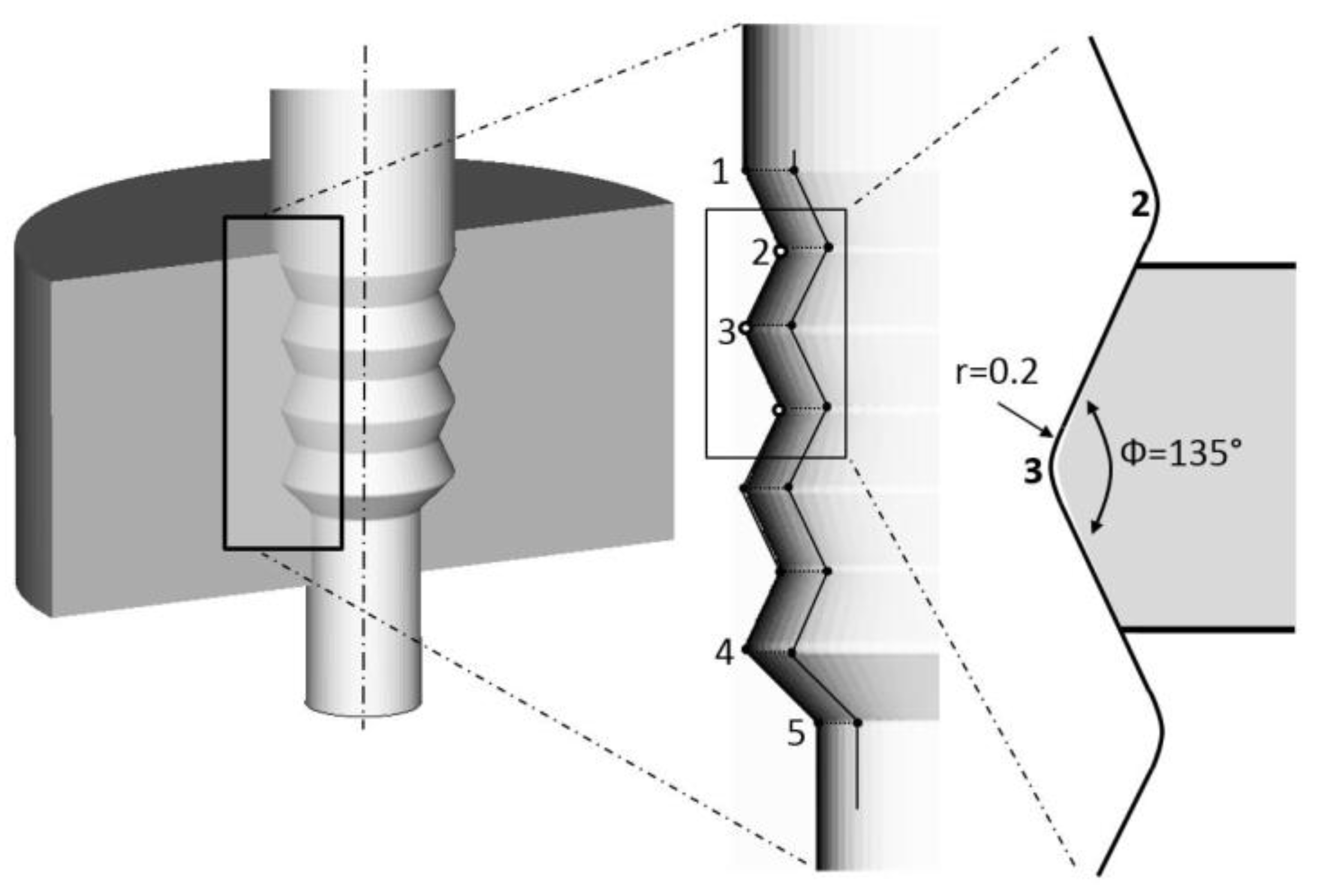
In contrast, for some practical applications there is a need for materials that provide a distinct gradient of mechanical properties. Classical approaches to obtaining property/microstructure gradients are, e.g., shot peening of ductile materials and heat treatment methods like the case hardening of steels. There are, furthermore, many techniques of surface coating which are applicable for almost every material, but are often accompanied by the formation of substrate-coating interfaces that can be disadvantageous for certain applications. For tailoring specific gradient microstructures and mechanical properties, SPD methods have rarely been used [23,24,25,26]. In the present work, a distinct microstructural gradient is created by a heterogeneous introduction of severe plastic deformation. Based on the principle of direct extrusion processing, a novel approach of gradation extrusion has recently been developed [27,28]. This bulk forming method is basically a type of direct impact extrusion that has also been registered for patent [29]. Using several geometrical cavities in the die that act as forming elements as well as enforcing a final reduction of the diameter of the rod-shaped billets (see Figure 1), a well-defined graded microstructure with a severely deformed surface region can be generated. The forming elements are comparatively small with regards to the overall die size. They can be varied in number, size, and arrangement and they generate the specific conditions needed for severe plastic deformation. Depending on the tool design, a specific local gradient in terms of grain size near the mantle surface can be produced [30]. The forming technique requires sufficient backpressure to completely fill the cavities with the material between the forming elements. This backpressure is generated by the final diameter reduction. Another important requirement for effective grain refinement is a large induced equivalent strain. The gradation extrusion principle is therefore characterized by a stepwise generation of local plastic strain at the forming elements which is accumulated during the deformation path through the corresponding tool [28,29].
This approach has a certain potential to produce an ultrafine-grained microstructure which can extend up to a depth of several millimeters from the billet’s surface. This layer is characterized by an increased strength while the inner material exhibits a high ductility due to its coarse-grained microstructure. Since the combination of local high strength and good ductility has high relevance for many practical applications, the investigated technological approach of gradation extrusion seems promising for bridging the gap between SPD methods refining the complete volume and conventional methods that only create surface strengthening in the micrometer regime. For an efficient tailoring of graded materials that are perfectly fit for a later application, it is important to generate an in-depth scientific understanding of microstructural evolution during processing and of the resulting (local) microstructure–properties relationships.

2. Materials and Methods

In order to generate graded rod-shaped materials, the process of gradation extrusion was developed. For detailed characterization of the microstructural evolution during processing, a unique extrusion die was designed and manufactured.
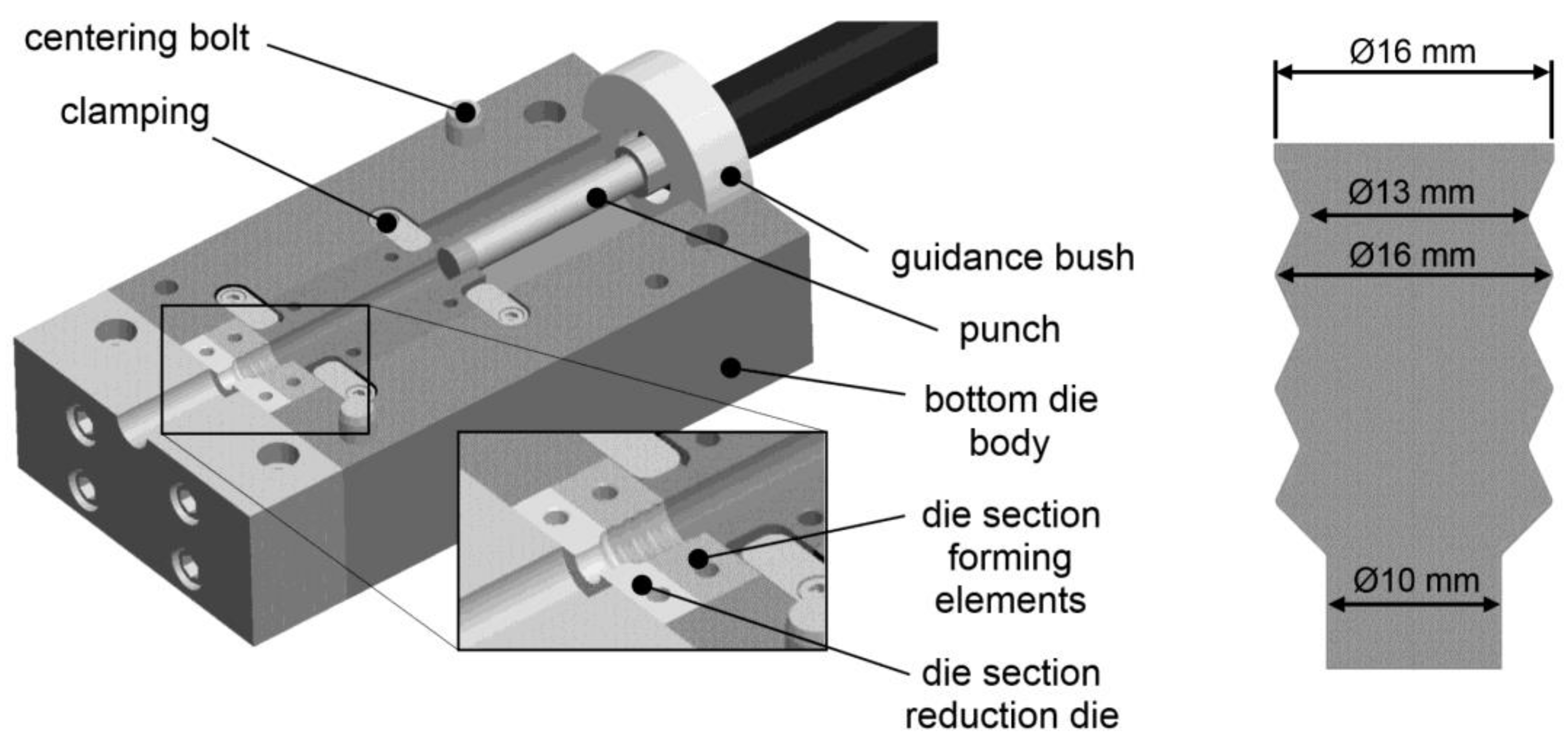
In contrast to conventional extrusion dies, the die is separated into an upper part and a lower die part. The separation plane is in the longitudinal direction and contains the axis of symmetry. This design allows for the removal of the processed billet. This is a basic requirement for a systematic characterization of microstructural evolution since the steady-state material flow is stopped at a certain point of extrusion. The billet can easily be removed without any damage or additional influence on the microstructure. The die parts are closed and compressed with a hydraulic press during forming, as presented in greater detail in [27]. The second distinct feature is another separation of the die into a gradation element and an extrusion element (see Figure 2). This design also allows different combinations (i.e., different relative contributions to the overall deformation) of gradation and extrusion.
The die was mounted in a hydraulic press with a maximum capacity of 15 MN in order to close the die parts. An additional horizontal hydraulic cylinder with a maximum capacity of 2.5 MN provided the necessary pressing force for gradation extrusion. The gradation extrusion was performed at room temperature. Due to the low pressing speed of 1 mm/s during the extrusion experiments, quasi-adiabatic heating was prevented. Note that the pressing speed is a major processing factor that influences several aspects of the forming process like temperature gradients and failure mechanisms. Further details on the influence of pressing speed in conjunction with other parameters such as die geometry are discussed elsewhere [28]. In order to reduce friction during the gradation extrusion experiments, a commercial lubricant spray containing molybdenum disulfide and graphite that is commonly used for SPD processes [31] was applied on the cavity surface. The initial diameter of the billets was 16 mm and the minimum diameter of the concave forming elements was 13 mm. The maximum diameter of the convex forming elements was 16 mm. The final reduction leads to a diameter of 10 mm (see Figure 2).
In this study, gradation extrusion was performed using an age-hardenable aluminum alloy AA6082. The chemical composition of the investigated material can be found in Table 1. Prior to processing, the initial AA6082 alloy was solid solution annealed and naturally aged (T4). This alloy is often used for extrusion due to its high formability and strength. The initial material was commercially hot extruded and exhibits a typical near-surface zone characterized by large equiaxed grains, which results from dynamic recrystallization and pronounced grain growth in this highly strained region [32,33,34].
After interrupted gradation extrusion, the billet was removed from the die and split lengthwise for mechanical and microstructural investigations. Hardness mapping (HV0.5) of an extruded billet was performed with the help of an automatic hardness tester (KB250BVRZ, KB Prüftechnik GmbH, Hochdorf-Assenheim, Germany). An equidistant grid was prepared with a spacing of 0.5 mm between individual indents and at a distance of 0.2 mm from the billet’s outer surface.
Microstructural evolution during gradation extrusion was investigated using the opposite part of the lengthwise-split billet. Surfaces of longitudinal sections were prepared as described in [35] with a final finishing step of vibrational polishing. All micrographs presented in this paper were recorded with a viewing direction parallel to the normal direction of the specimen. The microstructure was investigated by scanning electron microscopy (SEM) using a field-emission device (Zeiss NEON 40 EsB, Zeiss, Jena, Germany) equipped with a backscatter electron detector (BSD) and an electron backscatter diffraction (EBSD) system (OIM 5.2, EDAX TSL, Mahwah, NJ, USA) which was operated at 15 kV with the 60 µm aperture in high current mode. EBSD data sets were typically recorded in regions of interest of 250 µm × 1000 µm with a step size of 3 µm, and of 15 µm × 15 µm with a step size of 50 nm, respectively. The EBSD data were subjected to a slight cleanup procedure comprising neighbor confidence index (CI) correlation and grain CI standardization with a minimum confidence index of 0.1. Parameters for grain size and grain aspect ratio determination were set to 15° tolerance angle, a minimum of 5 hits per grain, and a minimum CI of 0.1.
In order to compare the effective strains during gradation extrusion with other SPD processes, Finite Element (FE) simulations were performed. The finite element simulation includes work hardening of the material and friction between die and sample. The simulation setup and processing simulation were performed using the software Simufact Forming (version 13.3). The processes were set up as rotationally symmetric 2D models since the investigated die geometries are rotationally symmetric. A total of 7209 elements (element length 0.3 mm) of type advancing front quad were used. Both tool parts (punch and die) were defined as rigid bodies. The material and friction description used for the numerical simulation are summarized in Table 2 [28], where ϕ corresponds to true strain.

3. Results and Discussion

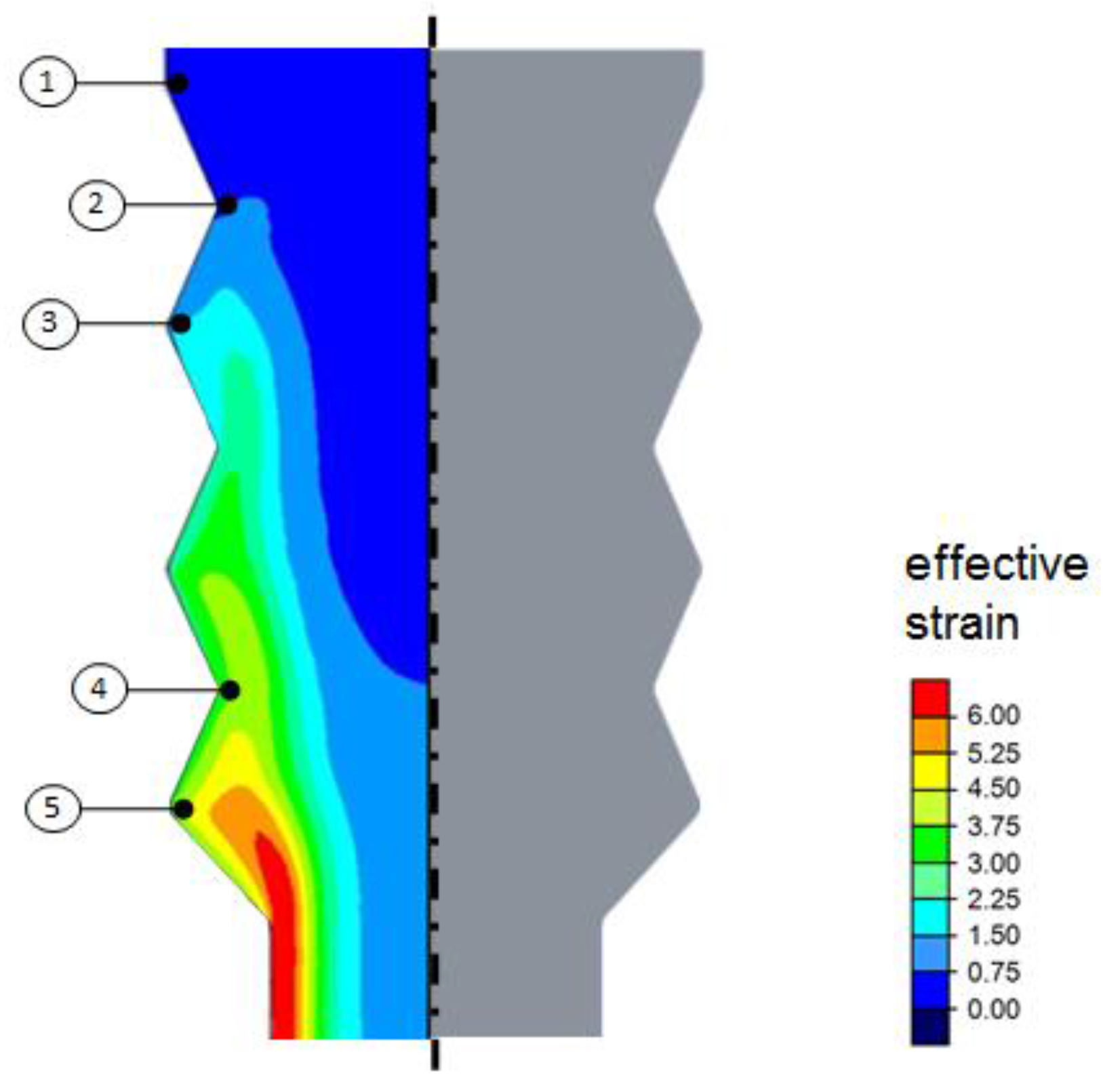
Figure 3 shows the distribution of effective (plastic) strain obtained from the FE simulation representing the steady state of material flow. A pronounced gradient of effective strain was found from the interior region to the surface. This gradient increases with every forming element in the axial direction. The final cross-sectional reduction leads to an additional introduction of strain, resulting in a final gradient ranging approximately from 1.4 (interior) to 6.9 (surface). The process basically fulfills the requirements for severe plastic deformation processes (SPD processes) since large effective strains, load path changes, high hydrostatic pressure, and temperatures below recrystallization temperature are applied. These results show that processing by gradation extrusion has a high potential for grain refinement by SPD, which leads to the assumption that distinct microstructural gradients may occur [28]. For a detailed analysis of the microstructure discussed below, five distinct locations are highlighted in Figure 3, representing interesting stages of deformation history during processing.
Figure 4 shows a processed billet of the investigated AA6082 alloy. The billet exhibits a smooth surface and no cracks have been found. It is also obvious that the cavities of all forming elements have been sufficiently filled with material, which indicates that the process of gradation extrusion was successfully performed. Both this experimental observation and the results of the FE simulation highlight that the requirements for a well-defined microstructural refinement by SPD are fulfilled.
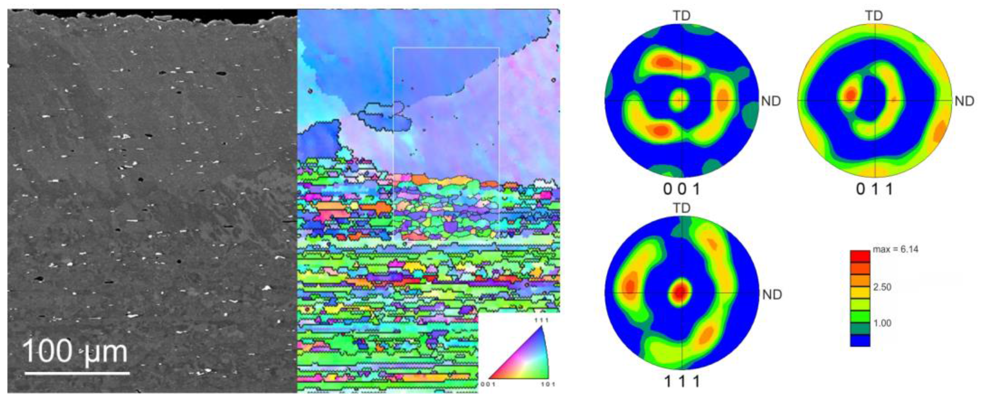
The initial material for gradation extrusion was first analyzed by SEM and EBSD (Figure 5). The microstructure of the commercially extruded AA6082 alloy is characterized by elongated fine grains in the interior region of the billet and by a surface area with a considerably coarsened grain structure. The mean grain size of the interior region is 10.2 (±2.3) µm and grains have a grain shape aspect ratio of 3. The shape of the grains in the interior region can be rationalized with the extrusion process of the initial material. This structure is a typical extrusion pancake structure [36]. The surface area has a thickness of approximately 200 µm and is characterized by almost equiaxed large grains with a diameter of about 150 µm. The exceptionally large shear strains introduced into the surface area, accompanied by quasi-adiabatic heating during commercial direct extrusion in conjunction with an overall high pressing temperature, lead to intensive dynamic recrystallization and grain growth in the surface area [36]. Furthermore, a typical strong <111> fiber texture accompanied by a <100> fiber texture caused by extrusion is found (see also Figure 5).
As already shown by the FE simulation (Figure 3), processing by gradation extrusion leads to microstructural changes due to incremental shear deformation by severe plastic deformation, especially in the surface area [36]. Figure 6 shows the contour of a gradation-extruded lengthwise-cut billet. The incremental deformation is realized by three concave and three convex, alternatingly arranged forming elements and by a subsequent reduction of the circular cross section. With the help of a hardness mapping on this lengthwise-split extrusion billet, a pronounced hardness gradient was documented. It was found that hardness does not change in the interior region while it rapidly increases (by 20%) in the surface area along the first concave and convex forming elements. At Point 3, the maximum hardness at the surface was observed. Moreover, these maximum hardness values were measured up to a depth of approximately 2 mm from the surface, which is the deepest uniformly distributed hardness all over the specimen.
From the point of view of obtaining a maximum gradation in terms of hardness, the processing should be finished after Point 3: Additional forming elements for gradation extrusion lead to a decrease in hardness and a less-pronounced gradient of mechanical properties at the second concave and convex forming elements. This can be rationalized with dynamic recovery and/or recrystallization due to undesired heating by friction and severe local straining. At the last concave and convex forming element (Point 4), an increase of hardness and, therefore, an increased gradient is observed again. It is assumed that a repeated increase in strain hardening caused by dislocation and defect multiplication of the dynamically recrystallized material leads to the observed increase in hardness. As a result, the last two concave and convex forming elements do not increase the hardness gradient. The final cavity involving a reduction of the cross section at Point 5 results in a homogenization of the hardness gradient, while the magnitude of the gradient itself remains. The zone of maximum hardness exhibits a constant width of approximately 1 mm and a thin transition region to the softer interior region of the billet is hardly affected by gradation extrusion.
The history of deformation during gradation extrusion that first has been characterized by hardness measurements was furthermore rationalized by accompanying microstructural investigations at the same five points of interest (Figure 6). For this investigation, the split billet was analyzed with the help of EBSD. Figure 6b–f corresponds to the points from the hardness mapping, respectively. At all five points, an EBSD measurement (at the same point) was performed using identical parameters. Each of Figure 6b–f shows an orientation map (OM) and the corresponding image quality map (IQ) below. This methodology allows a sufficient comparison of grain sizes, orientation data, and elongation of the grains at all five investigated points. The (severely strained) surface area is located on the left for each OM/IQ image. IQ maps give a qualitative indication of the magnitude of inherent strain. A brighter IQ image is associated with less lattice distortion and, therefore, lower inherent strains, and highly strained regions as well as grain boundaries typically show low/dark band contrast [37]. Note that microstructural features of the surface region are discussed in greater detail below (see also Figure 7).
Figure 6b corresponds to Point 1 and represents the initial condition of the material prior to gradation extrusion. As already shown in Figure 5, the surface area (~200 µm thickness) is characterized by almost equiaxed large grains (diameter ~150 µm) resulting from a pronounced dynamic recrystallization which is also confirmed by lower hardness values in this region. Underneath the coarse-grained surface region, the microstructure is characterized by elongated fine grains and a homogeneous pancake-like structure. The bright IQ image reveals a very low magnitude of inherent strain resulting from the commercial hot extrusion accompanied by pronounced recovery/recrystallization.
Figure 6c corresponds to Point 2 and represents the condition after the first concave forming element with an effective strain of approximately 1.4. Due to this severe plastic deformation, grain refinement occurs (comparable to other SPD microstructures) within the first 150 µm from the surface. The formerly coarse grains of the surface region are considerably refined compared to those of the interior region. Furthermore, a slight rotation of the grains can be observed originating from the material’s flow through the cavity at Point 2. From the orientation map, it can be concluded that after about 300 µm from the surface, the microstructure is almost similar to that of the interior region of the initial material. However, the introduced work hardening indicated by the dark IQ map extends to about 500 µm. Work hardening and grain refinement during this local severe plastic deformation led to a considerable increase in hardness.
Figure 6d corresponds to Point 3 and represents the condition after the first concave and convex forming element with an effective strain of approximately 2.1. The maximum hardness at this point can be rationalized by the additional strain hardening and grain refinement induced by SPD. Considerable grain refinement is found within a region of about 250 µm from the billet surface. Again, the highly strained region is much larger with approximately 700 µm from the surface, as shown by the corresponding IQ map. Furthermore, a slight change of the dominating crystallographic orientations is found in the interior region. The pancake structure does not proceed parallel to the surface anymore (originating from the extruded initial material) but fits along the geometry of the cavity inside the gradation extrusion die. The passing of one concave and one convex forming element led to exceptional grain refinement and work hardening of the surface region, which results in the maximum hardness.
Figure 6e corresponds to Point 4 and represents the condition after three concave and three convex forming elements with an effective strain of approximately 3.6. The shape of the grains appears to be more equiaxed than at the previously investigated point. The globular grain shape is an indication of dynamic recrystallization between Points 3 and 4, driven by friction- and strain-induced (quasi-adiabatic) heating and severe lattice distortion from an overall high defect density. There are almost no traces of a pancake structure left. The bright IQ map confirms the assumption of pronounced dynamic recrystallization and recovery all over the entire area investigated by EBSD (250 µm × 1000 µm). This is additionally confirmed by the decreased hardness between Points 3 and 4 in the surface area. The high hardness at Point 4 is mainly attributed to the fine-grained microstructure and not to work hardening (bright IQ map).
Interestingly, some shear localization can be observed in the EBSD measurement, which might be an indication for a very low local strain hardening rate of the material in this condition. One possible reason might be the evolution of the texture during processing, which might consequently lead to some kind of softening or kinematic hardening that supports the localization of strain even while recrystallization takes place. Additional microstructural analysis is needed for a more detailed understanding of the relationship between certain microstructural features and the occurrence of shear localization. Such shear localizations may also induce material damage at the surface of the specimen, which supports the conclusion that the gradation process is finalized just after the first cavity and no additional forming elements are needed. This finding also supports the need for careful characterization of the material’s shear behavior [38] from both experimental and theoretical points of view to minimize the risk of shear-induced cracking in SPD processes.
Figure 6f corresponds to Point 5 and represents the point after the final reduction of the specimen with an effective strain of approximately 4.3. This final reduction of the diameter leads to a reduction of the width of the maximum hardness region. This also results in an intensification of the hardness gradient (thin transition from surface to interior region) and in a homogenization of the microstructure within both regions.
Considering the results from Figure 6, it can be assumed that only one forming element and a final reduction cavity for the gradation extrusion process are sufficient from the point of gaining maximum hardness and maximum gradients. This is also beneficial from an economic point of view, since processing consumes less time and friction is simultaneously reduced, which decreases pressing forces and reduces the risk of material damage at the billet surface.
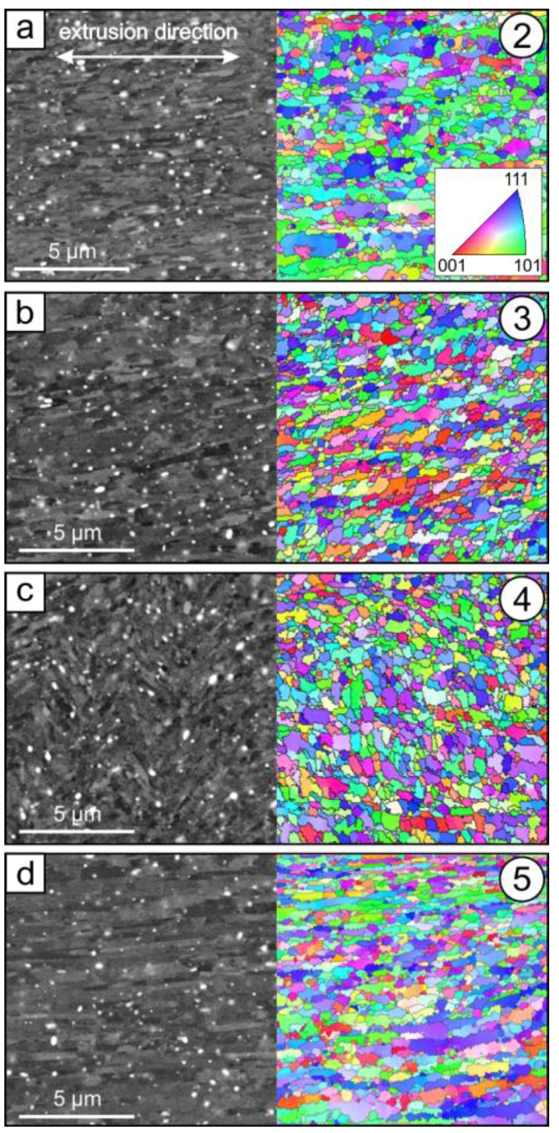
In Figure 7, a more detailed microstructural investigation of the fine-grained surface area is presented. SEM images and color-coded orientation maps from EBSD measurements of Points 2–5 are shown; the corresponding extrusion direction is highlighted in Figure 7a. Note that representative SEM images and the corresponding EBSD maps are taken from the same region but not from exactly the same area. With the help of the EBSD measurements, mean grain sizes and grain shape aspect ratios for the investigated points were derived (Table 3). Note that the white speckles in the SEM images are typical Fe-/Mn-rich precipitates [39] and are not further considered here. Figure 7a corresponds to the surface area at Point 2. As discussed earlier, a grain refinement due to SPD processing can be observed and the initially coarse-grained surface layer has been fully refined. The initial material at Point 1 exhibits an average grain size of about 150 µm in the surface area and 10.2 ± 2.3 µm in the interior region (see Table 3). The grain size at Point 2 is of ultrafine-grained (UFG) type with 0.79 ± 0.24 µm, and is homogeneously distributed. This result highlights that gradation extrusion is an effective process to provide the formation of numerous high-angle grain boundaries, resulting in a UFG microstructure. Note that the standard deviation of the grain size for all investigated locations is between 20 and 30% of the measured grain size, which is a characteristic value not originating from an uncertainty of the measurement but from the typical distribution of the grain size of SPD-processed materials. The corresponding grain shape (aspect ratio 2.7, see Table 3) remains almost unaffected compared with that in the initial structure (aspect ratio 3.0) since gradation extrusion introduces a shear deformation which also results in elongated grains.
Figure 7b shows the microstructure of the near-surface area at Point 3. The average grain size (0.60 ± 0.18) has been slightly reduced compared with the grain size at Point 2. Furthermore, the aspect ratio of the grains has also been slightly reduced to 2.5, indicating that the fraction of grains originating from the transformation of equiaxed dislocation cells into high-angle boundaries is increased.
The microstructure of the surface area at Point 4 (see Figure 7c) shows further changes: the former arrangement of elongated grains (see also Figure 6c,e) in the extrusion direction cannot be observed anymore. An ultrafine deformation microstructure with a grain size of 0.51 ± 0.16 µm can be observed with an aspect ratio of 2.1, which is slightly lower compared to those at Point 3. Interestingly, localized plastic deformation occurred at this stage. The corresponding SEM image reveals distinct shear localization and the presence of shear bands (see also Figure 8).
Figure 7d shows the microstructure of the near-surface area at Point 5, which represents the condition after the final reduction of the gradation extrusion. This final reduction leads again to an elongation of the grains parallel to the pressing direction. As a consequence of this extrusion step, the aspect ratio increases to 2.9. This is almost similar to the initial material, but compared to the initial material, the final grain size is significantly lower (0.66 ± 0.20 µm).
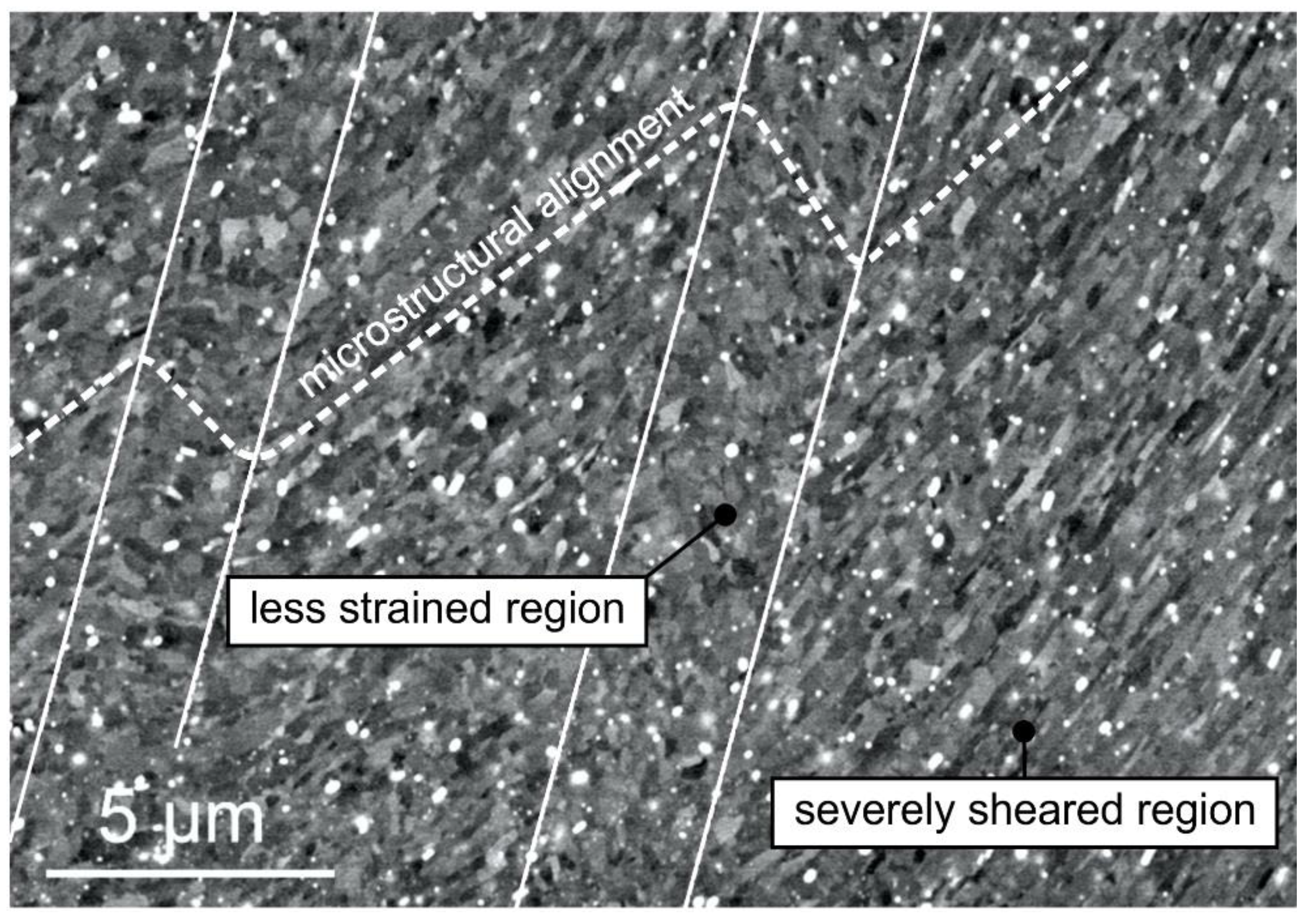
Figure 8 shows a SEM micrograph of a heterogeneously deformed region (see also Figure 7c). The alignment of elongated ultrafine grains (see dashed line in Figure 8) reveals the presence of two distinct band-like regions that have a width of several microns. An alternating arrangement of severely sheared regions next to regions with less strain is observed. These regions of localized straining are known to often act as initiation sites for cracking during further severe plastic deformation [40,41]. The absence of cracks in the billets after gradation extrusion indicates that microstructural gradients may also be beneficial in suppressing billet failure by shear localization.
4. Discussion and Conclusions

With the help of an adapted die design that allows an interruption in processing and nondestructive billet removal, a systematic study of microstructural evolution during gradation extrusion was successfully performed. Our results highlight that hardness as well as grain size do not considerably change beyond a certain point (Point 3) in the deformation history. There are several microstructural fluctuations following the path of deformation in the near-surface area, most likely induced by a complex interplay of work hardening and grain refinement accompanied by temperature-driven effects like dynamic recovery and recrystallization. While grain size and grain shape undergo only slight changes beyond that certain point (Point 3), the arrangements of elongated grains and their preferred crystallographic orientation change towards a typical SPD microstructure, which has also been generated, for example, by multi-pass ECAP in other studies. These results show that gradation extrusion is a powerful tool to produce graded materials with partially ultrafine-grained microstructures. From the point of view of obtaining an ultrafine-grained surface layer with maximum hardness, only a small number of forming elements that induce significant amounts of shear deformation is needed. In this study, one concave and one convex forming element were demonstrated to be sufficient to produce a homogeneous ultrafine-grained surface area. However, from the point of view of achieving a full annihilation of the initial lamellar microstructure and texture, a larger number of forming elements is needed. A wider region of homogeneous microstructure is found after deformation by 3 concave and 3 convex forming elements with a subsequent reduction of the billet diameter. However, it is found that this large incremental deformation may result in locally heterogeneous microstructures near the billet surface caused by localization of deformation. Since localized deformation like shear banding can act as a mechanism of material failure, too many forming elements during gradation extrusion are found to be disadvantageous. Finally, considering economical aspects of processing, fewer forming elements are preferred since several processing parameters (e.g., pressing force and processing duration) are significantly reduced.
In closing, we comment on the relevance of the new process of gradation extrusion presented here compared to the already well-established SPD methods. ECAP provides comparatively large billets and large strains by multi-pass processing that typically results in homogeneous microstructures with sub-micron grain sizes. HPT is often of high scientific interest due to the possibility to introduce extremely large strains by multiple turns resulting in many cases in nanometer-range grains. However, a major disadvantage is the limited material volume which is processed in small cylindrical specimens. ARB is a suitable SPD method for sheet material and laminated structures often resulting in grain elongation and sub-micron grain sizes. Gradation extrusion, as presented in this study, is a powerful tool for tailor-made surface modifications of rod-shaped billets and enables, for example, the combination of a conventionally grained ductile center and an ultrafine-grained hard surface; as such, it is a complementary and valuable addition to the well-established SPD techniques, especially in terms of future practical applications.

Acknowledgments

The authors gratefully acknowledge funding by the German Research Foundation (Deutsche Forschungsgemeinschaft, DFG) through the Collaborative Research Center SFB 692 (projects C5, A1, A4 and Z2).

Author Contributions

Philipp Frint coordinated the experiments, performed mechanical testing, analyzed and discussed the results of the experiments, structured and wrote the manuscript. Markus Härtel analyzed and discussed the results of the experiments, structured and wrote the manuscript. René Selbmann performed the deformation experiments and FE simulation, supported writing the manuscript. Dagmar Dietrich performed the EBSD measurements, discussed the results and supported writing the manuscript. Markus Bergmann coordinated and performed the deformation experiments and FE simulation. Thomas Lampke supervised the EBSD measurements and discussed the results. Dirk Landgrebe supervised the deformation experiments and discussed the results. Martin F.-X. Wagner supervised the experiments and discussed the results, supported writing the manuscript.

Conflicts of Interest

The authors declare no conflict of interest.

References

  1. Valiev, R.Z.; Islamgaliev, R.K.; Alexandrov, I.V. Bulk nanostructured materials from severe plastic deformation. Prog. Mater. Sci. 2000, 45, 103–189. [Google Scholar] [CrossRef]
  2. Langdon, T.G. Twenty-five years of ultrafine-grained materials: Achieving exceptional properties through grain refinement. Acta Mater. 2013, 61, 7035–7059. [Google Scholar] [CrossRef]
  3. Valiev, R.Z.; Langdon, T.G. Principles of equal-channel angular pressing as a processing tool for grain refinement. Prog. Mater. Sci. 2006, 51, 881–981. [Google Scholar] [CrossRef]
  4. Segal, V.M.; Reznikov, A.E.; Drobyshevskiy, A.E.; Kopylov, V.I. Plastic working of metals by simple shear. Russ. Metall. 1981, 1, 99–105. [Google Scholar]
  5. Frint, S.; Hockauf, M.; Frint, P.; Wagner, M.F.X. Scaling up segal’s principle of equal-channel angular pressing. Mater. Des. 2016, 97, 502–511. [Google Scholar] [CrossRef]
  6. Frint, P.; Hockauf, M.; Halle, T.; Strehl, G.; Lampke, T.; Wagner, M.F.X. Microstructural features and mechanical properties after industrial scale ECAP of an Al-6060 alloy. Mater. Sci. Forum 2011, 667–669, 1153–1158. [Google Scholar] [CrossRef]
  7. Saito, Y.; Tsuji, N.; Utsunomiya, H.; Sakai, T.; Hong, R.G. Ultra-fine grained bulk aluminum produced by accumulative roll-bonding (ARB) process. Scr. Mater. 1998, 39, 1221–1227. [Google Scholar] [CrossRef]
  8. Smirnova, N.A.; Levit, V.I.; Pilyugin, V.P.; Kuznetsov, R.I.; Davydova, L.S.; Sazonova, V.A. Evolution of structure of fcc single crystals during strong plastic deformation. Phys. Metals Metall. 1986, 61, 127–134. [Google Scholar]
  9. Zhilyaev, A.P.; Langdon, T.G. Using high-pressure torsion for metal processing: Fundamentals and applications. Prog. Mater. Sci. 2008, 53, 893–979. [Google Scholar] [CrossRef]
  10. Frint, P.; Hockauf, M.; Dietrich, D.; Halle, T.; Wagner, M.F.X.; Lampke, T. Influence of strain gradients on the grain refinement during industrial scale ECAP. Mater. Werkst. 2011, 42, 680–685. [Google Scholar] [CrossRef]
  11. Frint, P.; Hockauf, M.; Halle, T.; Wagner, M.F.X.; Lampke, T. The role of backpressure during large scale equal-channel angular pressing. Mater. Werkst. 2012, 43, 668–672. [Google Scholar] [CrossRef]
  12. Xu, C.; Langdon, T.G. Influence of a round corner die on flow homogeneity in ECA pressing. Scr. Mater. 2003, 48, 1–4. [Google Scholar] [CrossRef]
  13. Yoon, S.C.; Quang, P.; Hong, S.I.; Kim, H.S. Die design for homogeneous plastic deformation during equal channel angular pressing. J. Mater. Process. Technol. 2007, 187–188, 46–50. [Google Scholar] [CrossRef]
  14. Barber, R.E.; Dudo, T.; Yasskin, P.B.; Hartwig, K.T. Product yield for ecae processing. Scr. Mater. 2004, 51, 373–377. [Google Scholar] [CrossRef]
  15. Iwahashi, Y.; Furukawa, M.; Horita, Z.; Nemoto, M.; Langdon, T.G. Microstructural characteristics of ultrafine-grained aluminum produced using equal-channel angular pressing. Metall. Mater. Trans. A 1998, 29, 2245–2252. [Google Scholar] [CrossRef]
  16. Vorhauer, A.; Pippan, R. On the homogeneity of deformation by high pressure torsion. Scr. Mater. 2004, 51, 921–925. [Google Scholar] [CrossRef]
  17. Xu, C.; Horita, Z.; Langdon, T.G. The evolution of homogeneity in processing by high-pressure torsion. Acta Mater. 2007, 55, 203–212. [Google Scholar] [CrossRef]
  18. Estrin, Y.; Vinogradov, A. Extreme grain refinement by severe plastic deformation: A wealth of challenging science. Acta Mater. 2013, 61, 782–817. [Google Scholar] [CrossRef]
  19. Azushima, A.; Kopp, R.; Korhonen, A.; Yang, D.Y.; Micari, F.; Lahoti, G.D.; Groche, P.; Yanagimoto, J.; Tsuji, N.; Rosochowski, A.; et al. Severe plastic deformation (SPD) processes for metals. CIRP Ann. Manuf. Technol. 2008, 57, 716–735. [Google Scholar] [CrossRef]
  20. Dobatkin, S.V.; Szpunar, J.A.; Zhilyaev, A.P.; Cho, J.Y.; Kuznetsov, A.A. Effect of the route and strain of equal-channel angular pressing on structure and properties of oxygen-free copper. Mater. Sci. Eng. A 2007, 462, 132–138. [Google Scholar] [CrossRef]
  21. Hoseini, M.; Meratian, M.; Toroghinejad, M.R.; Szpunar, J.A. Texture contribution in grain refinement effectiveness of different routes during ECAP. Mater. Sci. Eng. A 2008, 497, 87–92. [Google Scholar] [CrossRef]
  22. Gholinia, A.; Prangnell, P.B.; Markushev, M.V. The effect of strain path on the development of deformation structures in severely deformed aluminium alloys processed by ECAE. Acta Mater. 2000, 48, 1115–1130. [Google Scholar] [CrossRef]
  23. Niehuesbernd, J.; Müller, C.; Pantleon, W.; Bruder, E. Quantification of local and global elastic anisotropy in ultrafine grained gradient microstructures, produced by linear flow splitting. Mater. Sci. Eng. A 2013, 560, 273–277. [Google Scholar] [CrossRef]
  24. Neugebauer, R.; Sterzing, A.; Bergmann, M. Mechanical properties of the AlSi1MgMn aluminium alloy (AA6082) processed by gradation rolling. Mater. Werkst. 2011, 42, 593–598. [Google Scholar] [CrossRef]
  25. Richert, M.; Petryk, H.; Stupkiewicz, S. Grain refinement in AlMgSi alloy during cyclic extrusion—Compression: Experiment and modelling. Arch. Metall. Mater. 2007, 52, 49–54. [Google Scholar]
  26. Lampke, T.; Dietrich, D.; Nickel, D.; Bergmann, M.; Zachäus, R.; Neugebauer, R. Controlled grain size distribution and refinement of an EN AW-6082 aluminium alloy. Int. J. Mat. Res. 2011, 102, 1–5. [Google Scholar] [CrossRef]
  27. Neugebauer, R.; Sterzing, A.; Selbmann, R.; Zachäus, R.; Bergmann, M. Gradation extrusion—Severe plastic deformation with defined gradient. Mater. Werkst. 2012, 43, 582–588. [Google Scholar] [CrossRef]
  28. Landgrebe, D.; Sterzing, A.; Schubert, N.; Bergmann, M. Influence of die geometry on performance in gradation extrusion using numerical simulation and analytical calculation. CIRP Ann. Manuf. Technol. 2016, 65, 269–272. [Google Scholar] [CrossRef]
  29. Zachäus, R.; Bergmann, M. Verfahren und Vorrichtung Zur Korngrössenbeeinflussung Eines Werkstückes Sowie Werkstück. DE 102012006952 B4. 2012.
  30. Neugebauer, R.; Bergmann, M. Local severe plastic deformation by modified impact extrusion process. In Steel Research International; WILEY-VCH Verlag GmbH & Co.: Weinheim, Germany, 2012. [Google Scholar]
  31. Frint, P.; Wagner, M.F.X.; Weber, S.; Seipp, S.; Frint, S.; Lampke, T. An experimental study on optimum lubrication for large-scale severe plastic deformation of aluminum-based alloys. J. Mater. Process. Technol. 2017, 239, 222–229. [Google Scholar] [CrossRef]
  32. Baumgarten, J.; Bunk, W.; Luecke, K. Extrusion textures in Al-Mg-Si alloys—1. Round extrusions. Z. Metall. Mater. Res. Adv. Tech. 1981, 72, 75–81. [Google Scholar]
  33. Sheppard, T.; Parson, N.C.; Zaidi, M.A. Dynamic recrystallization in Al-7Mg alloy. Metal Sci. 1983, 17, 481–490. [Google Scholar] [CrossRef]
  34. Sheppard, T. Extrusion of Aluminium Alloys, 1st ed.; Springer: Berlin, Germany, 1999. [Google Scholar]
  35. Dietrich, D.; Berek, H.; Schulze, A.; Scharf, I.; Lampke, T. EBSD and STEM on aluminum alloys subjected to severe plastic deformation. Prakt. Metall. Prac. Metall. 2011, 48, 136–150. [Google Scholar] [CrossRef]
  36. Berndt, N.; Frint, P.; Böhme, M.; Wagner, M.F.X. Microstructure and mechanical properties of an AA6060 aluminum alloy after cold and warm extrusion. Mater. Sci. Eng. A 2017, 707, 717–724. [Google Scholar] [CrossRef]
  37. Schwartz, A.J.; Kumar, M.; Adams, B.L.; Field, D.P. Electron Backscatter Diffraction in Materials Science; Springer: Berlin, Germany, 2009. [Google Scholar]
  38. Yin, Q.; Zillmann, B.; Suttner, S.; Gerstein, G.; Biasutti, M.; Tekkaya, A.E.; Wagner, M.F.-X.; Merklein, M.; Schaper, M.; Halle, T.; Brosius, A. An experimental and numerical investigation of different shear test configurations for sheet metal characterization. Int. J. Solids Struct. 2014, 51, 1066–1074. [Google Scholar] [CrossRef]
  39. Birol, Y. The effect of processing and Mn content on the T5 and T6 properties of AA6082 profiles. J. Mater. Process. Technol. 2006, 173, 84–91. [Google Scholar] [CrossRef]
  40. Antolovich, S.D.; Armstrong, R.W. Plastic strain localization in metals: Origins and consequences. Prog. Mater. Sci. 2014, 59, 1–160. [Google Scholar] [CrossRef]
  41. Lee, W.B.; Chan, K.C. A criterion for the prediction of shear band angles in F.C.C. Metals. Acta Metall. Mater. 1991, 39, 411–417. [Google Scholar] [CrossRef]
Figure 1. Gradation extrusion principle: Forming elements with undercuts, having an angle of 135° and a corner radius of 0.2 mm.
Metals 08 00096 g001
Figure 2. Tool system design for experiments [27] and channel diameters at the forming elements.
Metals 08 00096 g002
Figure 3. Distribution of effective strain determined from the FE simulation. Five distinct locations (1–5) for microstructural analysis, representing interesting stages of deformation history.
Metals 08 00096 g003
Figure 4. AA6082 billet processed by interrupted gradation extrusion.
Metals 08 00096 g004
Figure 5. Microstructure of the initial material prior to gradation extrusion (left to right: SEM, electron backscatter diffraction (EBSD) map, pole figures calculated from EBSD data). TD: Transverse; ND: normal direction.
Metals 08 00096 g005
Figure 6. Hardness (a) and microstructure (bf) of extruded material observed in a billet split lengthwise (step size 3 µm). Five distinct locations (1–5) for microstructural analysis, representing interesting stages of deformation history (see also Figure 3).
Metals 08 00096 g006
Figure 7. Microstructural details (ad) of the near surface region at Points 2–5 (see also Figure 6) during gradation extrusion (step size 50 nm). Extrusion direction shown in (a) applies to all figures.
Metals 08 00096 g007
Figure 8. SEM micrograph of a heterogeneously deformed region at Point 4.
Metals 08 00096 g008
Table 1. Chemical composition of the investigated AA6082 alloy.
ElementMgSiFeMnCuCrZnTiAl
wt %0.830.90.170.560.0470.0080.0050.019bal.
Table 2. Main parameters of the finite element (FE) model.
Material k f = K φ n K = 400 N m m 2 ; n = 0.094
FrictionCoulomb, maximum shear stress (combined) μ = 0.2 ; m = 0.08
Table 3. Grain sizes and aspect ratios after different deformation steps, determined from EBSD data with a step size of 50 nm.
LocationGrain Size/µmAspect Ratio
110.20 ± 2.303.0
20.79 ± 0.242.7
30.60 ± 0.182.5
40.51 ± 0.162.1
50.66 ± 0.202.9