Interface Characteristic of Explosive-Welded and Hot-Rolled TA1/X65 Bimetallic Plate

1
School of Mechanical and Electrical Engineering, Xi’an University of Architecture and Technology, Xi’an 710055, China
2
State Key Laboratory of Mechanical Behaviour for Materials, Xi’an JiaoTong University, Xi’an 710049, China
*
Author to whom correspondence should be addressed.
Metals 2018, 8(3), 159; https://doi.org/10.3390/met8030159
Submission received: 30 December 2017
/
Revised: 28 February 2018
/
Accepted: 1 March 2018
/
Published: 4 March 2018
(This article belongs to the Special Issue Laser Welding of Industrial Metal Alloys)
Abstract
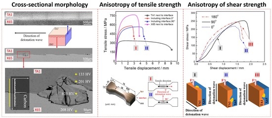
:TA1/X65 bimetallic plate has a bright future of application by combining the excellent corrosion resistance of TA1 and the high strength of inexpensive X65 steel, while manufacturing large size TA1/X65 bimetallic plate is still a challenging task. Multi-pass hot-rolling is the most common way to achieve a large size bimetallic plate. In this work, interface characteristic of explosive-welded and multi-pass hot-rolled TA1/X65 bimetallic plate is experimentally studied. The microstructure, composition and microhardness distribution across the TA1/X65 interface are investigated by optical metallographic observation, scanning electron microscope (SEM) observation, energy dispersive spectrometer (EDS) analysis, and Vickers hardness test. Shear tests and stratified tensile tests are conducted with emphasis on impacts of the angle between loading direction and detonation wave propagation direction on interface strength. A straight TA1/X65 interface with periodic morphology of residual peninsula could be observed on the cross section parallel to detonation wave propagation direction, while in most cases there is no residual peninsula morphology on the straight TA1/X65 interface when the cross section is perpendicular to detonation wave propagation direction. TA1/X65 interface of explosive-welded and multi-pass hot-rolled bimetallic plate presents higher bearing capacity for the load perpendicular to detonation wave propagation direction than that for the load parallel to detonation wave propagation direction. The results of this paper have a certain guiding significance for the fabrication of pipes and containers made of explosive-welded and hot-rolled TA1/X65 bimetallic plate.
1. Introduction
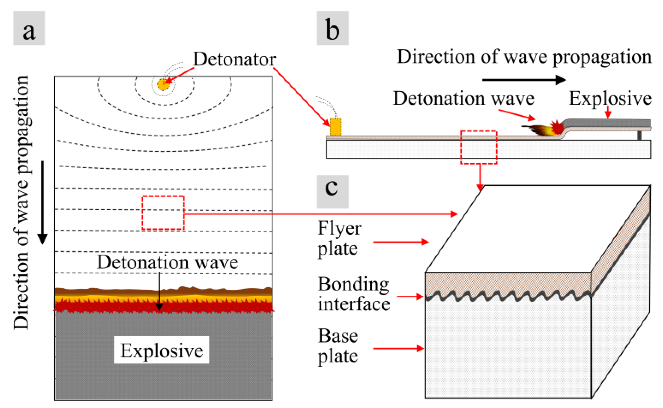
Explosive welding is one of the most widely used technologies to produce bimetallic sheets [1,2]. During the explosive welding process, the flyer plate impacts the base plate at a high velocity so that a metallurgical bonding interface between two metals can be formed in an instant and there is no significant crystallization and phase transition around the bounding interface [3,4,5,6,7]. With advantages of high bonding strength, favorable material adaptation, and applicable to large-scale machining, explosive welding has been widely used in manufacturing bimetal or multi-metal clad plates [8,9,10]. In particular, this method is very suitable for welding dissimilar metal materials with a significant difference in melting temperature, thermal expansion coefficients, or mechanical properties [11,12,13]. The explosive welding method is demonstrated in Figure 1 [14,15,16].
When traditional fusion welding methods are employed to weld Ti and steel, brittle Fe–Ti intermetallic compounds will be formed in the weld bead. Explosive welding is very suitable for joining Ti and steel. The titanium/steel bimetallic plates with titanium or its alloys as the flyer materials and steel as the base materials can combine the excellent corrosion resistance of titanium and the favourable mechanical property of steel [17,18], and they can not only improve the service life of components but also significantly decrease the total material cost [19,20]. For example, titanium/steel bimetallic plate has been widely used in petroleum, chemical, and other industry fields for manufacturing pipelines, storage tanks, and reactors [21]. Compared to the titanium-steel bimetallic plate, it is worth mentioning that the aluminum-steel bimetallic plate also provides a low-cost solution for the manufacture of reliable composite parts. Because of their different functional characteristics, titanium-steel bimetallic plates and aluminum-steel bimetallic plates are used in large-scale pipeline and marine structures, respectively. Both of them have their respective advantages and their relevant application industries can complement each other [22,23,24,25]. Usually, a thin flyer layer of Ti is employed to reduce the total cost of Ti/Steel plate, while the corrosion life of flyer layer directly depends on its thickness. Therefore, the Al/Steel plate is much more suitable than the Ti/Steel joint when a thick flyer layer is needed, for the reason of cost saving.
This article focuses on the explosion welded titanium-steel bimetallic plate. The increasing demand for natural gas and oil has, in turn, resulted in an increasing demand for the refining and transportation of highly corrosive crude oil and natural gas. Bimetallic sheets in which TA1 is used as the material of the flyer plate instead of steel can greatly improve the life of the refining equipment and pipeline. In recent years, researchers have conducted many studies on the microstructure and mechanical properties [26,27,28,29,30,31,32,33,34,35], heat treatment [36,37,38], hot rolling process [39], residual stress [40], bonding mechanism [41,42,43] and butt welding process [44,45] of explosive bonded Ti/Steel bimetallic sheets. These work mainly focused on the bimetallic sheet itself, while investigation regarding the suitability of explosive bonded Ti/Steel bimetallic sheet for the subsequent process, such as the JCOE process (progressive forming process of ‘J’ forming, ‘C’ forming and ‘O’ forming, reducing gap, welding and mechanical expanding), was rather limited. The Ti/Steel bimetallic sheets discussed in this work would be used for pipelines and refining equipment and therefore would subjected to multiple bending process (i.e., JCOE process). The deformation and strain of bimetallic sheet would be extremely heterogeneous during JCOE process and this might accelerate the local shear failure at Ti/Steel interface. Aiming to minimize the risk of local failure at the Ti/Steel interface during JCOE process, this work focused more on the dependency of bonding strength of Ti/Steel interface on the direction of shear load. Compared with the published literature and the author’s previous work, results of this study may have more guiding significance to the subsequent JCOE process of bimetallic sheets. This work also revealed the inhomogeneity of both microstructure and mechanical properties of the Ti/Steel bimetallic sheet. With the detailed information about the mechanical properties of the bimetallic sheet, a more realistic simulation model of the JCOE processing of Ti/Steel bimetallic sheet will be created in the future and used to conduct a simulation-based optimization of the JCOE process.
2. Experimental Materials and Methods
2.1. Materials
The available diameter and length of a single tube is limited by the width and length of the bimetallic plate, respectively. In the present work, an 8 mm thick TA1 plate and 58 mm thick X65 plate were explosively bonded by using ammonium nitrate fuel-oil mixture as explosive material. Chemical composition of TA1 plate and X65 plate is listed in Table 1 and Table 2, respectively. Then, the as-welded 66 mm thick TA1/X65 plate was subjected to the hot rolling processes at air atmosphere to reduce the thickness and increase the length and width. The temperature of plate was about 850 °C when the hot rolling process started and was approximately 610 °C when the hot rolling process stopped. The rolling direction is the same as the detonation wave propagation direction. The descending distance of the upper roller in each single-pass rolling process did not exceed 20% of the plate thickness. TA1/X65 plate with a size of 16 mm × 2000 mm × 10,000 mm was finally achieved. The final thickness of the TA1 layer and X65 layer was about 2 mm and 14 mm, separately.
2.2. Experimental Methods
Specimens with size of 10 mm × 10 mm × 16 mm were cut from the TA1/X65 clad plate under the condition that one of the cross sections was parallel to the direction of detonation wave propagation. Two adjacent cross sections of the specimen were ground and polished. Then, the TA1 flyer plate and the X65 base plate were sequentially etched with the solution of 8 mL HNO3 + 2 mL HF + 90 mL H2O for 20 s and 4% nitric acid alcohol solution for 15 s, respectively. The microstructure near the bonding interface of the bimetallic plate was observed by using Nikon Eclipse MA200 optical microscope (Minato-ku, Tokyo, Japan) and LS-JLLH-22 scanning electron microscope (SEM) (HITACHI, Tokyo, Japan), and the compositions of the interface were analyzed by using the energy disperse spectroscopy (EDS) (HITACHI, Tokyo, Japan). Finally, the Vickers microhardness distribution near the bonding interface was measured under the load of 200 gf for 15 s.
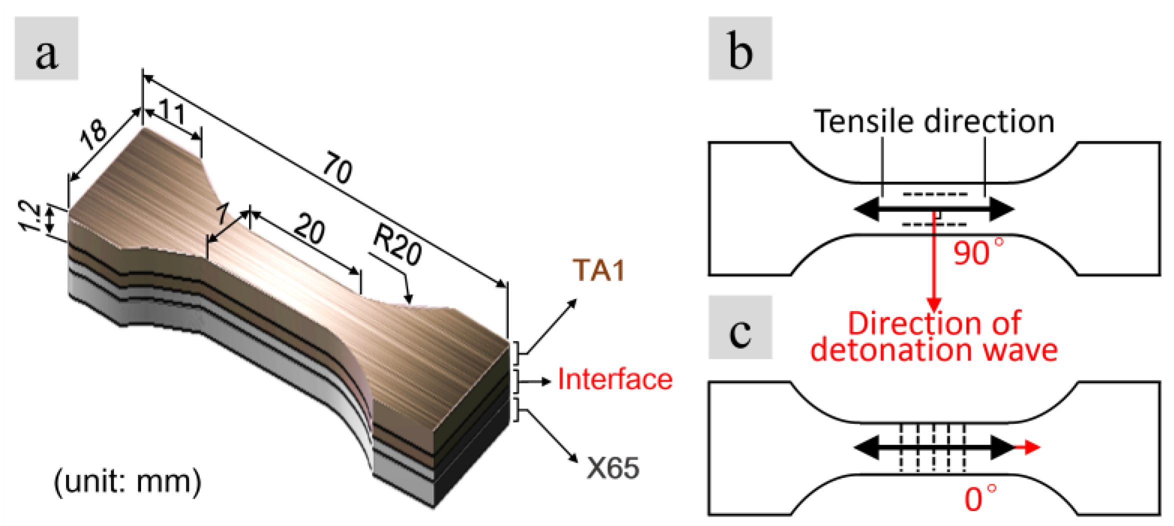
The stratified-tensile tests were applied in this study to investigate the relationship between the tensile mechanical properties and the tensile directions. In the stratified-tensile tests maintain the stretching rate constant, the clad plate was successively cut into 1.2 mm-thick layers along the thickness direction from the flyer plate side to the base plate side (Figure 2a). Additionally, the sampling schemes shown in Figure 2b,c were adopted during the machining, namely, the tensile direction was perpendicular to the direction of detonation wave propagation in one case (Figure 2b), and the two directions were parallel to each other in the other case (Figure 2c). Table 3 shows the sample numbers in tensile tests.
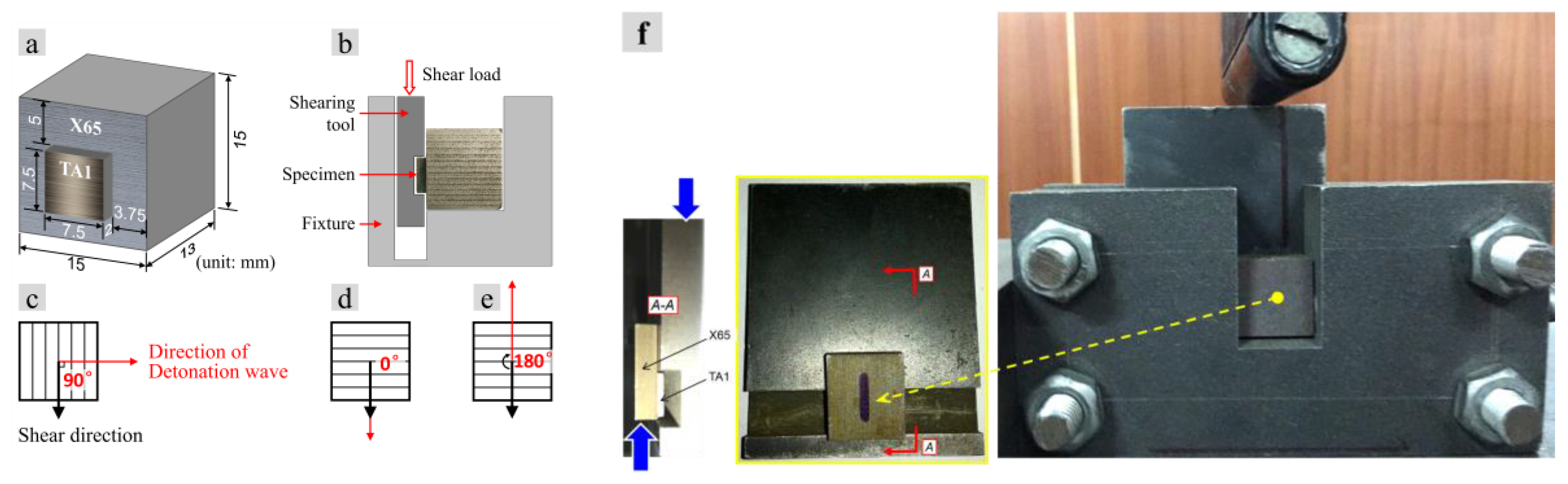
To examine the bonding strength of the interface, the compression-shear tests were applied. Shear specimens were cut from the CP-Ti/X65 bimetallic sheet. Shear tests were performed on a universal mechanical testing machine (Brooke, Beijing, China) at a loading speed of 0.2 mm/min. Figure 3a,b illustrate the specimen size and the implementation method of the tests, respectively. As mentioned above, the bonding interface probably exhibits anisotropic compression-shear properties due to the directional interface morphology [46]. Therefore, as shown in Figure 3c–e, the angles between the shear direction and the direction of detonation wave propagation were set to 90°, 0°, and 180°, respectively. Table 4 shows sample numbers in tensile tests.
3. Results and Discussion
3.1. Microstructure Observation and Composition Analysis
As shown in Figure 4b, the bonding interface of as-welded TA1/X65 bimetallic sheet had a wavy morphology. Figure 4c,g–l show that a substantial part of the as-welded TA1/X65 interface can be identified by a sharp transition between the TA1 and the X65 materials and the region over which there was a significant change in Ti content was approximately 2–3 μm wide. Figure 4d shows the transition zone between TA1 and local melted zone, from which it can be seen that the width of the transition zone between TA1 and the local melted zone was less than 5 μm. Namely, alloy element diffusion in an as-welded TA1/X65 joint was quite limited [21].
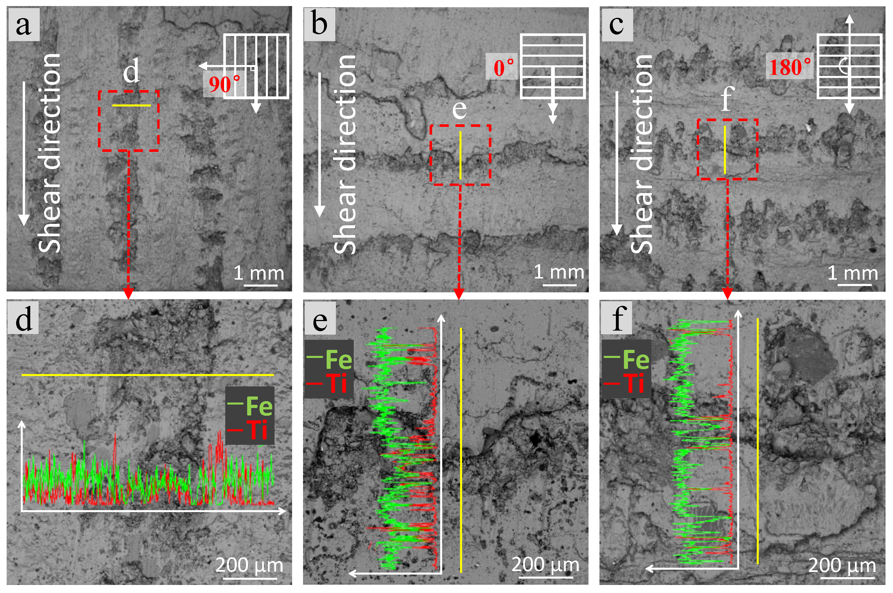
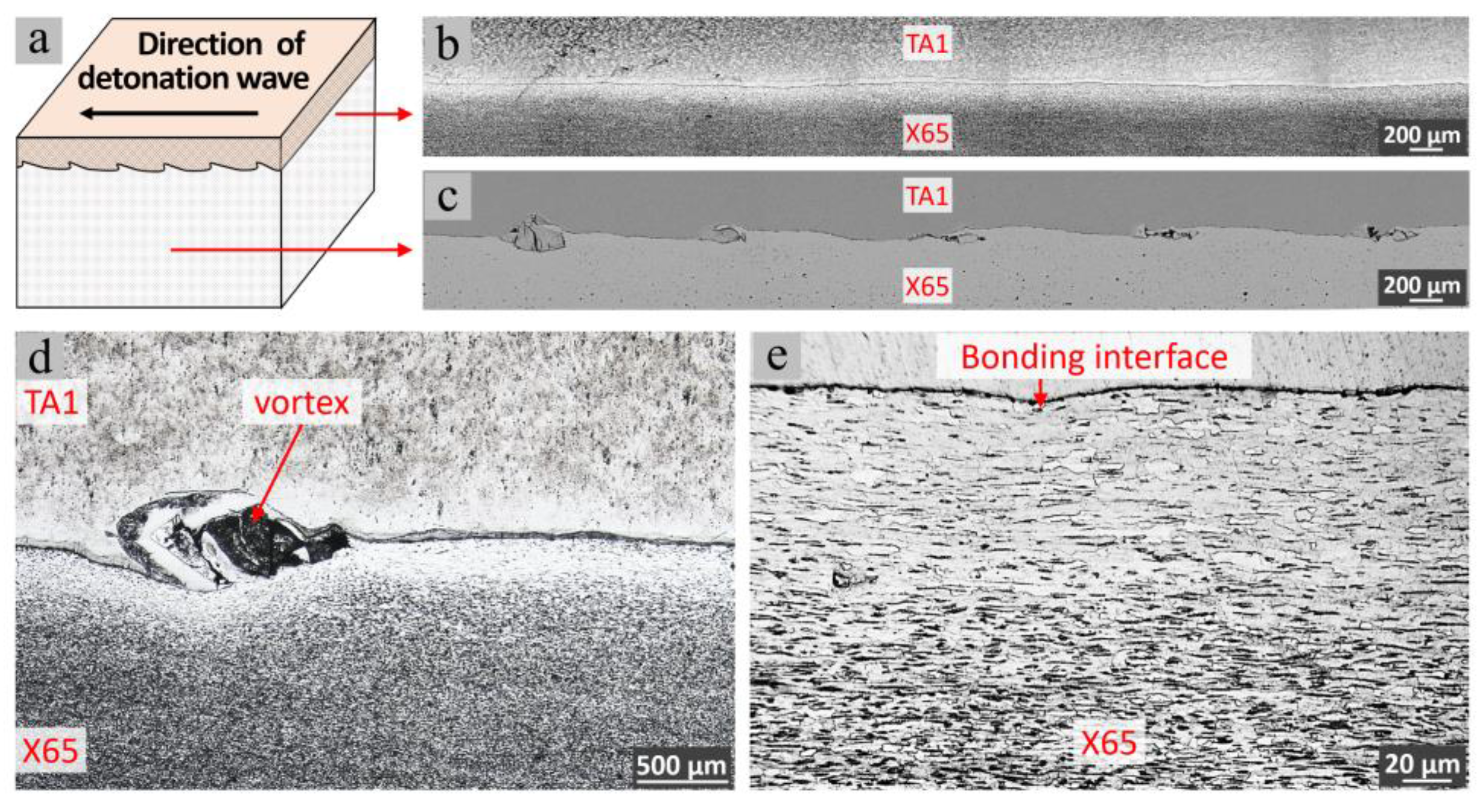
Figure 5 displays the metallographic structure of the bonding interface. The bonding interface was approximately straight when the cross section was perpendicular to the direction of detonation wave propagation (Figure 5b). Periodic morphology of residual peninsula could be observed on the wave-like TA1/X65 interface, when the cross section was parallel to the detonation wave propagation direction (Figure 5c). The waves were seriously asymmetric and the X65 steel wave crests slanted in the direction of detonation wave propagation. The distances between the wave crests and the amplitude of the wave were 1200–1600 μm and 100–300 μm, respectively. The vortices at the front slopes of X65 steel wave crests and a gray thin layer with a thickness of 10–15 μm between titanium and steel could be observed in Figure 5d. As shown in Figure 5e, the microstructure of the X65 included ferrite grains (bright) and pearlite grains (dark) with a band pattern characteristic. It can be seen from Figure 5e that the closer the section of the X65 zone to the interface, the less the percentage of pearlite, which might be due to the decarbonization of the X65 steel near the interface. Ti is more active than Fe and can easily seize C atoms. In addition, intense plastic deformation occurred in the metals near the interface of the bimetallic sheet, and a large number of lattice defects might be formed inside the metals during the explosive welding process and the subsequent hot-rolling process, which provided diffusion channels for C [19].
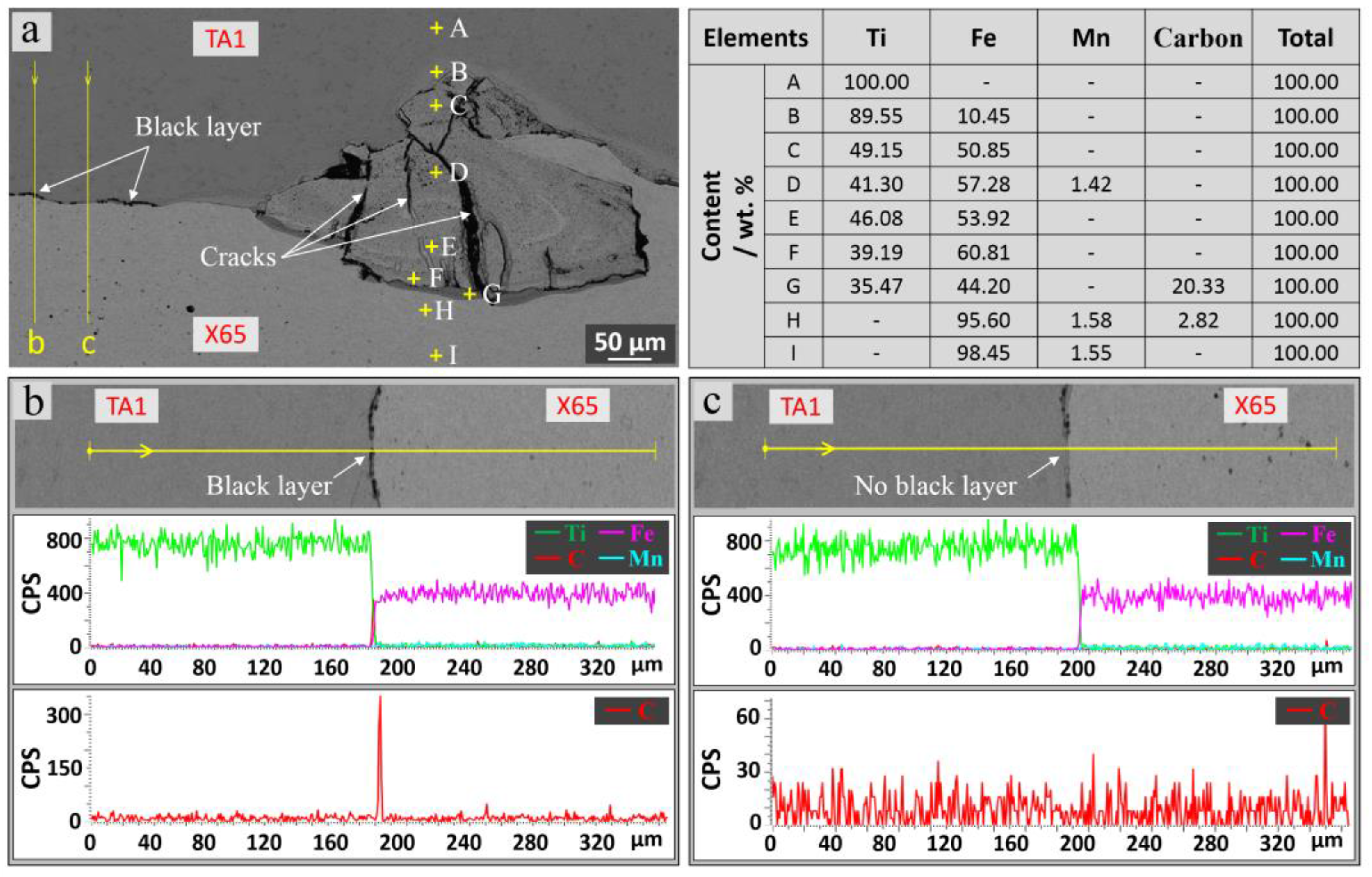
Figure 6 displays the micro-morphology and element distribution around the vortex structure. There were numerous cracks in the vortex, and some black thin layers were discontinuously distributed on the straight bonding interface (Figure 6a). The results of the elemental analysis show that the light gray region (point B) between the TA1 substrate and the vortex was an Fe diffusion layer, and the vortex structure (points C–F) was a mixture where titanium and steel melted. Additionally, the contents of carbon element at the interface between the vortex and the X65 steel base material were much higher than that of X65 steel base material (points G and H). As shown in Figure 6b,c, there was no obvious diffusion region of Ti and Fe at the straight bonding interface, while a mono-peak of carbon element was observed at the place where the black layer existed (Figure 6b). Therefore, the so-called black layer was actually the result of the segregation phenomena of carbon element, and Jiang et al. [47] also observed this phenomenon in their study.
The vortex shown in Figure 6a formed due to the liquid metal jet in the front of the detonation wave propagation was intercepted during the explosive welding [48,49], where multiple elements such as Ti, Fe, C, and Mn were mixed and dissolved to produce various hard and brittle intermetallic compounds including FeTi, Fe2Ti and TiC [50,51], and cracks were easy to be formed in the vortex during the rolling process.
3.2. Microhardness Distribution
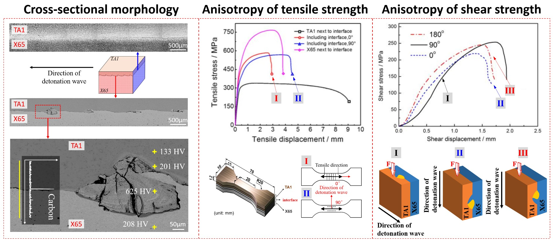
Figure 7 shows the microhardness distribution across the bonding interface. The microhardness of TA1 and X65 far away from interface were measured to be approximately 128 HV and 216 HV, respectively. In the vicinity of the bonding interface, there was no appreciable change in the microhardness of TA1 layer, while the microhardness of X65 layer dropped to about 155 HV.
In researches of explosive-welded bimetals without post-weld heat treatment [52,53,54,55], the considerable increase of the microhardness near the bonding interface could be observed, and the microhardness decreased as the distance from the bonding interface increased. This phenomenon was attributed to the intense plastic deformation in the welding zone adjacent to the interface. In the present investigation, the TA1/X65 bimetallic plate was heat-treated and hot-rolled after explosive welding process, so the deformation effects were partly removed and the microhardness near the bonding interface decreased obviously due to the annealing of the material [56].
Figure 7c shows the microhardness distribution of the vortex. The microhardness of the light grey region (201 HV) between TA1 parent material and the vortex was significantly larger than that of the TA1 parent metal. This might be because the light grey region was composed of the supersaturated solid solution and Ti2Fe intermetallic compounds due to the diffusion of Fe [52]. The microhardness of peninsula structure in the front of X65 steel wave crest (171 HV) and the region of X65 steel close to the vortex (165 HV) was greatly lower than that of the X65 parent metal, and this softening phenomenon could be explained by the annealing effect near the interface. As the mixture of TA1 and X65 steel, the vortex zone is composed of various hard compounds, especially in the inner of the vortex microhardness up to 625 HV is observed.
3.3. Stratified-Tensile Tests
Figure 8a,b separately display the morphologies of the tension test specimens and the tensile curves. As shown in this figure, the tensile strengths of TA1 titanium layer and the X65 steel layer were, respectively, 340 MPa and 765 MPa, and their elongations after the break were, respectively, about 47% and 19%. As for specimens including TA1/X65 interface, the tensile strengths and the elongations after the break were, respectively, 585 MPa and 14% when the tensile direction was parallel to the detonation wave propagation direction (indicated as 0°), while they were, respectively, 565 MPa and 25% when the tensile direction was perpendicular to the detonation wave propagation direction (indicated as 90°). Additionally, the wrinkled morphology perpendicular to the tensile direction was found near the fracture of specimen indicated as 0° after it the tensile test, while the surface of specimen indicated as 90° was smooth.
As shown in Figure 9 and Figure 10, the bonding interface of specimens including TA1/X65 interface cracked and detached after the tensile tests. When the tensile direction was parallel to the direction of detonation wave propagation, the fracture significantly bent towards the TA1 side. Fragment-like morphology was found between TA1 and X65 layers in the cracked fractures and both Ti and Fe elements were detected in the fragments-like morphology (Figure 9e). When the tensile direction was perpendicular to the direction of detonation wave propagation, the fracture also bent towards the TA1 side, whereas the bending degree was lower than that of specimen indicated by 0°. The fracture between TA1 and X65 layers was smooth, and the residual morphology of wave crests of X65 steel could be found at the interface (marked by circles in Figure 10a).
The tensile strength of specimen indicated by 0° was 15 MPa higher than that of specimen indicated by 90°, while the elongation after fracture of the former one was significantly lower than that of the latter one. The analysis revealed that the differences in the tensile strengths and elongations after fracture of two specimens including TA1/X65 interface was probably related to the directional wave-like bonding interface. When the tensile direction was parallel to the direction of detonation wave propagation, the wave crests on the flyer layer side and the crests on the base layer side mutually meshed [46]; meanwhile, the waves also damaged the continuity of constriction of the tensile specimens.
It is worth noting that the fracture of specimens including TA1/X65 interface stretched along two directions both bent towards the TA1 layer side. This phenomenon was mainly because of a significant difference in the mechanical properties between the TA1 layer and X65 layer.
3.4. Compression-Shear Tests
Figure 11 shows the results of the shear test. It can be seen from Figure 11 that when the shear direction was same (i.e., 0°), perpendicular (i.e., 90°) and opposite (i.e., 180°) to the detonation wave propagation direction, and the shear strengths of TA1/X65 interface were 219 MPa, 254 MPa, and 245 MPa, respectively. Figure 11 also indicates that the largest shear-displacement before the fracture was observed when the shear direction was perpendicular to the detonation wave propagation direction.
Figure 12 displays the morphology and element distribution of the sheared fractures at the X65 side. It can be seen from Figure 11 that all the three fractures obtained under different shear directions consisted of the bright zone and dark zone. According to the results of EDS analysis, the dark zone should be the residual morphology of vortex zone, which is composed of supersaturated solid solution and brittle intermetallic compounds, while the bright zone on the fracture might be the residual morphology of the bonding region with a narrow interface layer. When the shear direction is perpendicular to the detonation wave propagation direction, the bright zone presents a relatively large dimension in the direction of shear load. The difference in shear strength between a shear direction parallel to a detonation wave propagation direction and the shear direction perpendicular to the detonation wave propagation direction might relate to the mechanical locking effect of the wavy interface. As reported by Bai et al., the waves in the TA1 side and X65 steel side are interlocked. When the loading direction is the same to that of detonation wave propagation, separation of upper waves from the lower waves is subjected to a relatively low resistance. Thus, the shear strength under a load parallel to detonation wave propagation direction is lower than that under a load perpendicular to the detonation wave propagation direction.
4. Conclusions
The interface characteristic of explosive-welded and hot-rolled TA1/X65 bimetallic plate was studied in this work. The main findings can be summarized as follows:
(1) TA1/X65 interface of explosive-welded and multi-pass hot-rolled bimetallic plate was approximately a straight interface on the cross section perpendicular to the detonation wave propagation direction. Periodic morphology of residual peninsula could be observed on the wave-like TA1/X65 interface, when the cross section was parallel to the detonation wave propagation direction.
(2) The vortex consisted of hard and brittle intermetallic compounds and numerous cracks were formed in the vortex zone after explosively welding and multi-pass hot rolling process. Fe element diffusion was detected in the TA1 region. The closer the section of X65 to the interface, the less the percentage of pearlite in the section.
(3) The section of the X65 zone far from the interface had a Vickers hardness value of approximately 216 HV, and the section of the TA1 zone far from the interface had a Vickers hardness value of approximately 128 HV. However, micro-hardness values up to 625 HV were measured at the locations where the residual peninsula was observed.
(4) TA1/X65 interface of explosive-welded and multi-pass hot-rolled bimetallic plate has higher bearing capacity for the external load perpendicular to the detonation wave propagation direction than that for the external load parallel to the detonation wave propagation direction.
Acknowledgments
This work was supported by the National High Technology Research and Development Program of China (Grant No. 2013AA031303HZ).
Author Contributions
Miao-Xia Xie and Ting-Ting Xu conceived and designed the experiments; Qing-Lin Bai and Xiang-Tao Shang performed the experiments; Lin-Jie Zhang contributed materials; Qing-Lin Bai, Xiang-Tao Shang and Lin-Jie Zhang analyzed the data; Miao-Xia Xie and Ting-Ting Xu wrote the paper. All authors have discussed the results, read and approved the final manuscript.
Conflicts of Interest
The authors declare no conflict of interest.
References
- Gulenc, B. Investigation of interface properties and weldability of aluminum and copper plates by explosive welding method. Mater. Des. 2008, 29, 275–278. [Google Scholar] [CrossRef]
- Loureiro, A.; Mendes, R.; Ribeiro, J.B.; Leal, R.M. Effect of explosive ratio on explosive welding quality of copper to aluminium. Ciência Tecnologia dos Materiais 2017, 29, 46–50. [Google Scholar] [CrossRef]
- Mendes, R.; Ribeiro, J.B.; Loureiro, A. Effect of explosive characteristics on the explosive welding of stainless steel to carbon steel in cylindrical configuration. Mater. Des. 2013, 51, 182–192. [Google Scholar] [CrossRef] [Green Version]
- Kwiecień, M.; Majta, J.; Dziedzic, D. Shear deformation and failure of explosive welded inconel-microalloyed steels bimetals. Arch. Civ. Mech. Eng. 2014, 14, 32–39. [Google Scholar] [CrossRef]
- Athar, M.M.H.; Tolaminejad, B. Weldability window and the effect of interface morphology on the properties of Al/Cu/Al laminated composites fabricated by explosive welding. Mater. Des. 2015, 86, 516–525. [Google Scholar] [CrossRef]
- Chen, P.; Feng, J.; Zhou, Q.; An, E.; Li, J.; Yuan, Y.; Ou, S. Investigation on the explosive welding of 1100 aluminum alloy and AZ31 magnesium alloy. J. Mater. Eng. Perform. 2016, 25, 2635–2641. [Google Scholar] [CrossRef]
- Tricarico, L.; Spina, R. Experimental investigation of laser beam welding of explosion-welded steel/aluminum structural transition joints. Mater. Des. 2010, 31, 1981–1992. [Google Scholar] [CrossRef]
- Bataev, I.A.; Bataev, A.A.; Mali, V.I.; Pavliukova, D.V. Structural and mechanical properties of metallic-intermetallic laminate composites produced by explosive welding and annealing. Mater. Des. 2012, 35, 225–234. [Google Scholar] [CrossRef]
- Aceves, S.M.; Espinosa-Loza, F.; Elmer, J.W.; Huber, R. Comparison of Cu, Ti and ta interlayer explosively fabricated aluminum to stainless steel transition joints for cryogenic pressurized hydrogen storage. Int. J. Hydrogen Energ. 2015, 40, 1490–1503. [Google Scholar] [CrossRef]
- Findik, F. Recent developments in explosive welding. Mater. Des. 2011, 32, 1081–1093. [Google Scholar] [CrossRef]
- Gloc, M.; Wachowski, M.; Plocinski, T.; Kurzydlowski, K.J. Microstructural and microanalysis investigations of bond titanium grade1/low alloy steel st52-3N obtained by explosive welding. J. Alloys Compd. 2016, 671, 446–451. [Google Scholar] [CrossRef]
- Borchers, C.; Lenz, M.; Deutges, M.; Klein, H.; Gärtner, F.; Hammerschmidt, M.; Kreye, H. Microstructure and mechanical properties of medium-carbon steel bonded on low-carbon steel by explosive welding. Mater. Des. 2016, 89, 369–376. [Google Scholar] [CrossRef]
- Carvalho, G.H.S.F.L.; Mendes, R.; Leal, R.M.; Galvão, I.; Loureiro, A. Effect of the flyer material on the interface phenomena in aluminium and copper explosive welds. Mater. Des. 2017, 122, 172–183. [Google Scholar] [CrossRef]
- Akbari-Mousavi, S.A.A.; Barrett, L.M.; Al-Hassani, S.T.S. Explosive welding of metal plates. J. Mater. Process. Technol. 2008, 202, 224–239. [Google Scholar] [CrossRef]
- Amani, H.; Soltanieh, M. Intermetallic phase formation in explosively welded Al/Cu bimetals. Metall. Mater. Trans. B 2016, 47, 2524–2534. [Google Scholar] [CrossRef]
- Raghukandan, K. Analysis of the explosive cladding of Cu-low carbon steel plates. J. Mater. Process. Technol. 2003, 139, 573–577. [Google Scholar] [CrossRef]
- Rao, N.V.; Reddy, G.M.; Nagarjuna, S. Structure and properties of explosive clad hsla steel with titanium. Trans. Indian Inst. Metals 2014, 67, 67–77. [Google Scholar]
- Groschopp, J.; Heyne, V.; Hofmann, B. Explosively clad titanium steel composite. Weld. Int. 2010, 1, 879–883. [Google Scholar] [CrossRef]
- Malyutina, Y.N.; Skorohod, K.A.; Shevtsova, K.E.; Chesnokova, A.V. Multilayered titanium-steel composite produced by explosive welding. AIP Conf. Proc. 2015, 1683. [Google Scholar] [CrossRef]
- Nishida, M.; Chiba, A.; Honda, Y.; Hirazumi, J.I.; Horikiri, K. Electron microscopy studies of bonding interface in explosively welded Ti/steel clads. ISIJ Int. 1995, 35, 217–219. [Google Scholar] [CrossRef]
- Xie, M.X.; Zhang, L.J.; Zhang, G.F.; Zhang, J.X.; Bi, Z.Y.; Li, P.C. Microstructure and mechanical properties of CP-Ti/X65 bimetallic sheets fabricated by explosive welding and hot rolling. Mater. Des. 2015, 87, 181–197. [Google Scholar] [CrossRef]
- Corigliano, P.; Crupi, V.; Guglielmino, E.; Sili, A.M. Full-field analysis of Al/Fe explosive welded joints for shipbuilding applications. Mar. Struct. 2018, 57, 207–218. [Google Scholar] [CrossRef]
- Corigliano, P.; Crupi, V.; Fricke, W.; Guglielmino, E. Low-Cycle Fatigue Life Prediction of Fillet-Welded Joints in Ship Details. In Proceedings of the 18th International Conference on Ships and Shipping Research, Bari, Italy, 22–24 June 2005; Ali, M., Esposito, F., Eds.; Springer: London, UK, 2015. [Google Scholar]
- Corigliano, P.; Crupi, V.; Fricke, W.; Friedrich, N.; Guglielmino, E. Experimental and numerical analysis of fillet-welded joints under low-cycle fatigue loading by means of full-field techniques. Proc. Inst. Mech. Eng. Part C J. Mech. Eng. Sci. 2015, 229, 1327–1338. [Google Scholar] [CrossRef]
- Crupi, V.; Guglielmino, E.; Sili, A.; Tata, M.E.; Costanza, G. Metallurgical characterization of an explosion welded aluminum/steel joint. La Metall. Italiana 2016, 11, 17–22. [Google Scholar]
- Sudha, C.; Prasanthi, T.N.; Paul, V.T.; Saroja, S.; Vijayalakshmi, M. Assessment of mechanical property of Ti-5Ta-2Nb and 304L SS explosive clad and correlation with microstructure. Procedia Eng. 2014, 86, 42–50. [Google Scholar] [CrossRef]
- Ning, J.; Zhang, L.J.; Xie, M.X.; Yang, H.X.; Yin, X.Q.; Zhang, J.X. Microstructure and property inhomogeneity investigations of bonded Zr/Ti/steel trimetallic sheet fabricated by explosive welding. J. Alloys Compd. 2017, 698, 835–851. [Google Scholar] [CrossRef]
- Sudha, C.; Prasanthi, T.N.; Paul, V.T.; Saroja, S.; Vijayalakshmi, M. Metastable phase transformation in Ti-5Ta-2Nb alloy and 304L austenitic stainless steel under explosive cladding conditions. Metall. Mater. Trans. A 2012, 43, 3596–3607. [Google Scholar] [CrossRef]
- Prasanthi, T.N.; Sudha, C.; Murugesan, S.; Paul, V.T.; Saroja, S. Reverse transformation of deformation-induced phases and associated changes in the microstructure of explosively clad Ti-5Ta-2Nb and 304L SS. Metall. Mater. Trans. A 2015, 46, 4429–4435. [Google Scholar] [CrossRef]
- Prasanthi, T.N.; Sudha, C.; Parida, P.K.; Dasgupta, A.; Saroja, S. Prediction and confirmation of phases formed in the diffusion zone of Ti-5Ta-2Nb/304L SS explosive clads. Metall. Mater. Trans. A 2015, 46, 1519–1534. [Google Scholar] [CrossRef]
- Saksl, K.; Ostroushko, D.; Mazancová, E.; Szulc, Z.; Milkovič, O.; Ďurišin, M.; Balga, D.; Ďurišin, J.; Rütt, U.; Gutowski, O. Local structure of explosively welded titanium-stainless steel bimetal. Int. J. Mater. Res. 2015, 106, 621–627. [Google Scholar] [CrossRef]
- Somasundaram, S.; Krishnamurthy, R.; Kazuyuki, H. Effect of process parameters on microstructural and mechanical properties of Ti-SS 304L explosive cladding. J. Cent. South Univ. 2017, 24, 1245–1251. [Google Scholar] [CrossRef]
- Kurek, A.; Wachowski, M.; Niesłony, A.; Płociński, T.; Kurzydłowski, K.J. Fatigue tests and metallographic of explosively cladded steel-titanium bimetal. Arch. Metall. Mater. 2014, 59, 1565–1570. [Google Scholar] [CrossRef]
- Sudha, C.; Prasanthi, T.N.; Saroja, S.; Vijayalakshmi, M. Effect of heat treatment on the microstructure and microchemistry of explosive welded joints of Ti-5Ta-1.8Nb and 304L SS. Indian Weld. J. 2011, 44, 53–68. [Google Scholar] [CrossRef]
- Wachowski, M.; Gloc, M.; Ślęzak, T.; Płociński, T.; Kurzydłowski, K.J. The effect of heat treatment on the microstructure and properties of explosively welded titanium-steel plates. J. Mater. Eng. Perform. 2017, 26, 945–954. [Google Scholar] [CrossRef]
- Prasanthi, T.N.; C. Sudha, R.; Saroja, S. Explosive cladding and post-weld heat treatment of mild steel and titanium. Mater. Des. 2016, 93, 180–193. [Google Scholar] [CrossRef]
- Zhao, G.; Huang, Q.; Zhou, C.; Yang, X.; Liu, G.; Lifeng, M.A. Investigation of hot rolling influence on the explosive-welded clad plate. Mater. Sci. 2016, 22, 486–490. [Google Scholar] [CrossRef]
- Karolczuk, A.; Kowalski, M.; Kluger, K.; Żok, F. Identification of residual stress phenomena based on the hole drilling method in explosively welded steel-titanium composite. Arch. Metall. Mater. 2014, 59, 1119–1123. [Google Scholar] [CrossRef]
- Prasanthi, T.N.; Sudha, C.; Saroja, S. Effect of alloying elements on interdiffusion phenomena in explosive clads of 304L SS/Ti-5Ta-2Nb alloy. J. Mater. Sci. 2016, 51, 5290–5304. [Google Scholar] [CrossRef]
- Jiang, H.; Yan, X.; Liu, J.; Zeng, S.; Duan, X. Diffusion behavior and mathematical model of ti-steel explosive clad plate during heat treatment. Rare Metal Mater. Eng. 2015, 44, 972–976. [Google Scholar]
- Zu, G.; Sun, X.; Zhang, J.; University, N. Interfacial bonding mechanism and mechanical performance of Ti/steel bimetallic clad sheet produced by explosive welding and annealing. Rare Rare Metal Mater. Eng. 2017, 46, 906–911. [Google Scholar]
- Chu, Q.; Zhang, M.; Li, J.; Yan, C. Experimental and numerical investigation of microstructure and mechanical behavior of titanium/steel interfaces prepared by explosive welding. Mater. Sci. Eng. A 2017, 689, 323–331. [Google Scholar] [CrossRef]
- Li, Y.; Liu, C.; Yu, H.; Zhao, F.; Wu, Z. Numerical simulation of Ti/Al bimetal composite fabricated by explosive welding. Metals 2017, 7, 407. [Google Scholar] [CrossRef]
- Chu, Q.L.; Zhang, M.; Li, J.H.; Jin, Q.; Fan, Q.Y.; Xie, W.W.; Luo, H.; Bi, Z.Y. Experimental investigation of explosion-welded CP-Ti/Q345 bimetallic sheet filled with Cu/V based flux-cored wire. Mater. Des. 2015, 67, 606–614. [Google Scholar] [CrossRef]
- Ning, J.; Zhang, L.J.; Jiang, G.C.; Xie, M.X.; Yin, X.Q.; Zhang, J.X. Narrow gap multi-pass laser butt welding of explosion welded CP-Ti/Q235b bimetallic sheet by using a copper interlayer. J. Alloys Compd. 2017, 701, 587–602. [Google Scholar] [CrossRef]
- Bai, Q.L.; Zhang, L.J.; Xie, M.X.; Yang, H.X.; Zhang, J.X. An investigation into the inhomogeneity of the microstructure and mechanical properties of explosive welded H62-brass/Q235b-steel clad plates. Int. J. Adv. Manuf. Technol. 2016, 90, 1351–1363. [Google Scholar] [CrossRef]
- Jiang, H.T.; Kang, Q.; Yan, X.Q. A novel diffusion model considering curvature radius at the bonding interface in a titanium/steel explosive clad plate. Int. J. Min. Metall. Mater. 2015, 22, 956–965. [Google Scholar] [CrossRef]
- Acarer, M.; Gülenç, B.; Findik, F. The influence of some factors on steel/steel bonding quality on there characteristics of explosive welding joints. J. Mater. Sci. 2004, 39, 6457–6466. [Google Scholar] [CrossRef]
- Bataev, I.A.; Bataev, A.A.; Mali, V.I.; Burov, V.G.; Prikhod’Ko, E.A. Formation and structure of vortex zones arising upon explosion welding of carbon steels. Phys. Met. Metallogr. 2012, 113, 233–240. [Google Scholar] [CrossRef]
- Mousavi, S.A.A.A.; Sartangi, P.F. Experimental investigation of explosive welding of cp-titanium/AISI 304 stainless steel. Mater. Des. 2009, 30, 459–468. [Google Scholar] [CrossRef]
- Song, J.; Kostka, A.; Veehmayer, M.; Raabe, D. Hierarchical microstructure of explosive joints: Example of titanium to steel cladding. Mater. Sci. Eng. A 2011, 528, 2641–2647. [Google Scholar] [CrossRef]
- Raghukandan, K.; Rathinasabapathi, M.; Vaidyanathan, P.V.; Balasubramanian, V. An experimental investigation on the effect of h/D ratio on dynamic form—Cladding of domes. J. Mater. Process. Technol. 1997, 63, 55–59. [Google Scholar] [CrossRef]
- Zhang, L.J.; Pei, Q.; Zhang, J.X.; Bi, Z.Y.; Li, P.C. Study on the microstructure and mechanical properties of explosive welded 2205/X65 bimetallic sheet. Mater. Des. 2014, 64, 462–476. [Google Scholar] [CrossRef]
- Chiba, A.; Nishida, M.; Morizono, Y.; Imamura, K. Bonding characteristics and diffusion barrier effect of the tic phase formed at the bonding interface in an explosively welded titanium/high-carbon steel clad. J. Phase Equilibria 1995, 16, 411–415. [Google Scholar] [CrossRef]
- Bazarnik, P.; Adamczyk-Cieślak, B.; Gałka, A.; Płonka, B.; Snieżek, L.; Cantoni, M.; Lewandowska, M. Mechanical and microstructural characteristics of Ti6Al4V/AA2519 and Ti6Al4V/AA1050/AA2519 laminates manufactured by explosive welding. Mater. Des. 2016, 111, 146–157. [Google Scholar] [CrossRef]
- Rao, N.V.; Sarma, D.S.; Nagarjuna, S.; Reddy, G.M. Influence of hot rolling and heat treatment on structure and properties of hsla steel explosively clad with austenitic stainless steel. Metal Sci. J. 2009, 25, 1387–1396. [Google Scholar] [CrossRef]
Figure 1.
Schematic of explosive welding process and the typical bonding interfacial morphology: (a) top view of explosion welding; (b) side view of explosive welding; and (c) typical bonding interface.
Figure 1.
Schematic of explosive welding process and the typical bonding interfacial morphology: (a) top view of explosion welding; (b) side view of explosive welding; and (c) typical bonding interface.

Figure 2.
The specimen size and the sampling scheme of the tensile tests: (a) specimen size; (b) 90°; and (c) 0°.
Figure 2.
The specimen size and the sampling scheme of the tensile tests: (a) specimen size; (b) 90°; and (c) 0°.

Figure 3.
Schematic of: (a) the specimen size; (b) shear test; and (c–e) sampling schemes; (f) universal mechanical testing machine.
Figure 3.
Schematic of: (a) the specimen size; (b) shear test; and (c–e) sampling schemes; (f) universal mechanical testing machine.

Figure 4.
Test results for as-welded TA1/X65 bimetallic sheet by Xie et al. [21] (a) macrograph of cross-section; (b) wavy interface; (c) typical morphology of the wavy interface; (d) high-resolution image (HRI) and micro-zone analysis results (MAR) of position D in panel c; (e–l) results of line scanning.
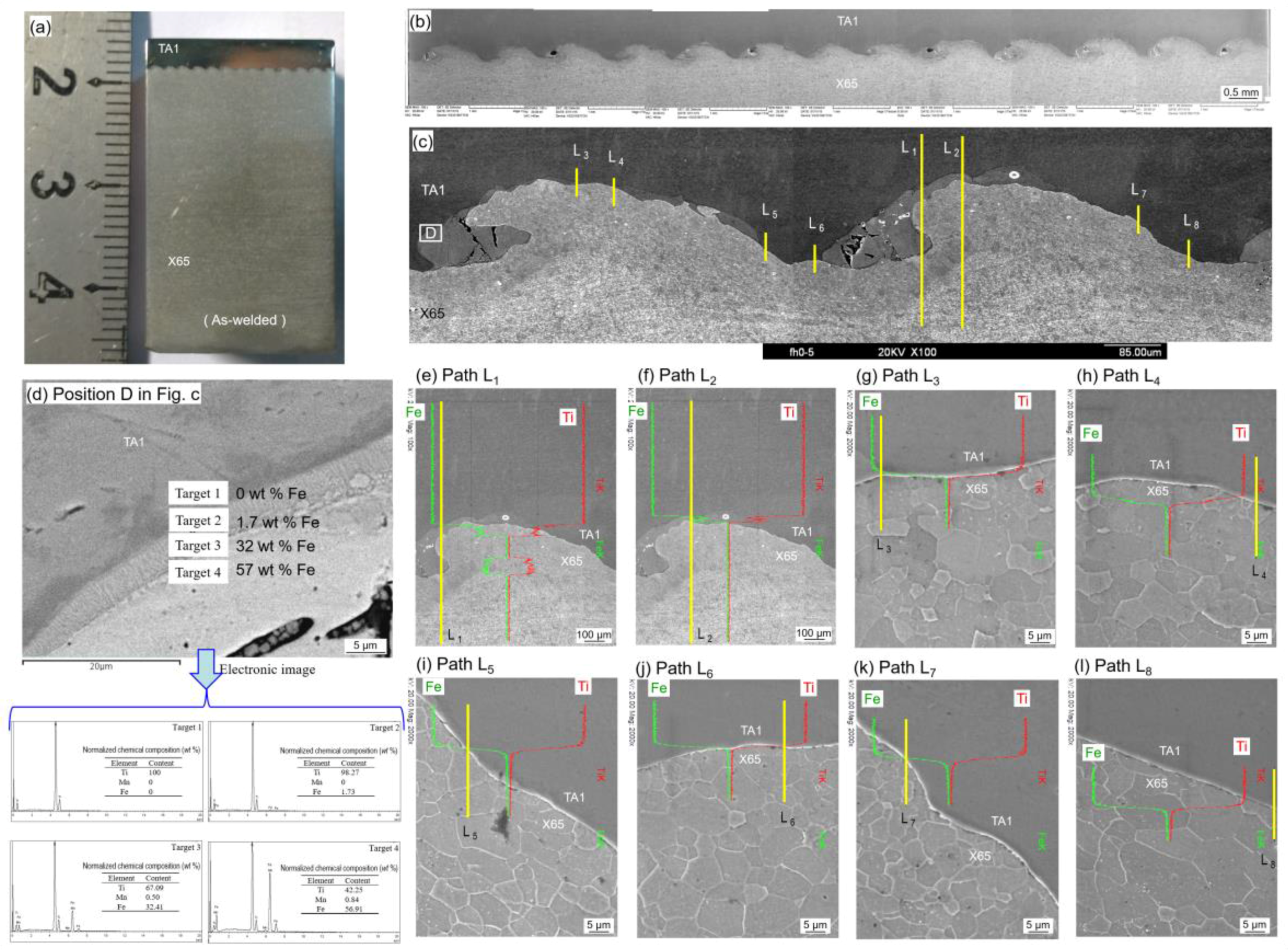
Figure 5.
The microstructure observed on the cross sections of TA1/X65 clad plate: (a) different interface; (b) cross section was perpendicular to the direction of detonation wave propagation; (c) cross section was parallel to the direction of detonation wave propagation; (d) vortex; and (e) bonding interfacial.

Figure 6.
The distribution of elements at the interface of the TA1/X65 clad plate: (a) points and lines; (b) black layer; and (c) no black layer.
Figure 6.
The distribution of elements at the interface of the TA1/X65 clad plate: (a) points and lines; (b) black layer; and (c) no black layer.

Figure 7.
Microhardness profile across the interface of the TA1/X65 clad plate: (a) bonding interface; (b) microhardness; and (c) points microhardness.
Figure 7.
Microhardness profile across the interface of the TA1/X65 clad plate: (a) bonding interface; (b) microhardness; and (c) points microhardness.
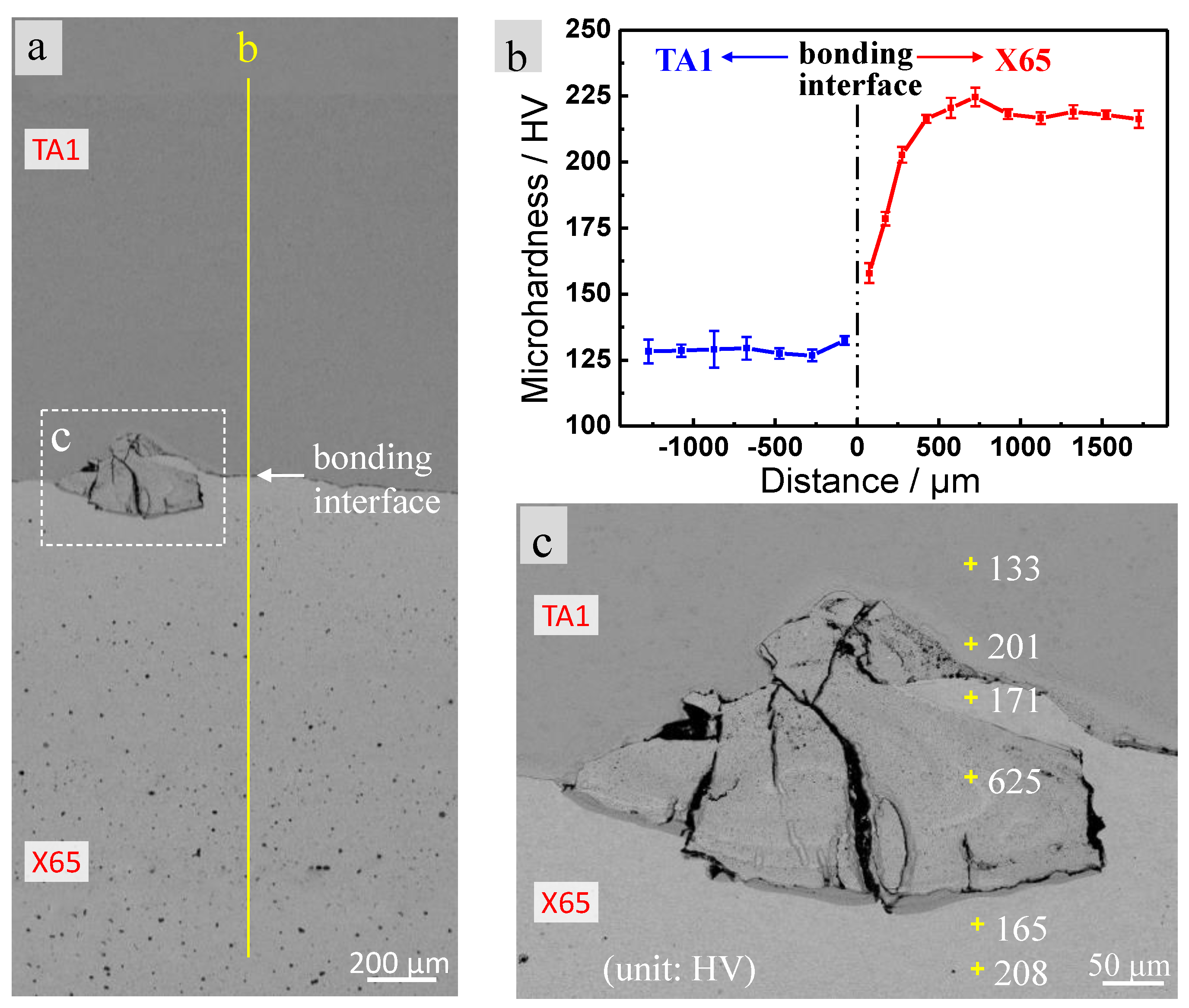
Figure 8.
(a) Morphologies of the specimens; and (b) the stress-displacement curves acquired from the stratified-tensile tests.
Figure 8.
(a) Morphologies of the specimens; and (b) the stress-displacement curves acquired from the stratified-tensile tests.
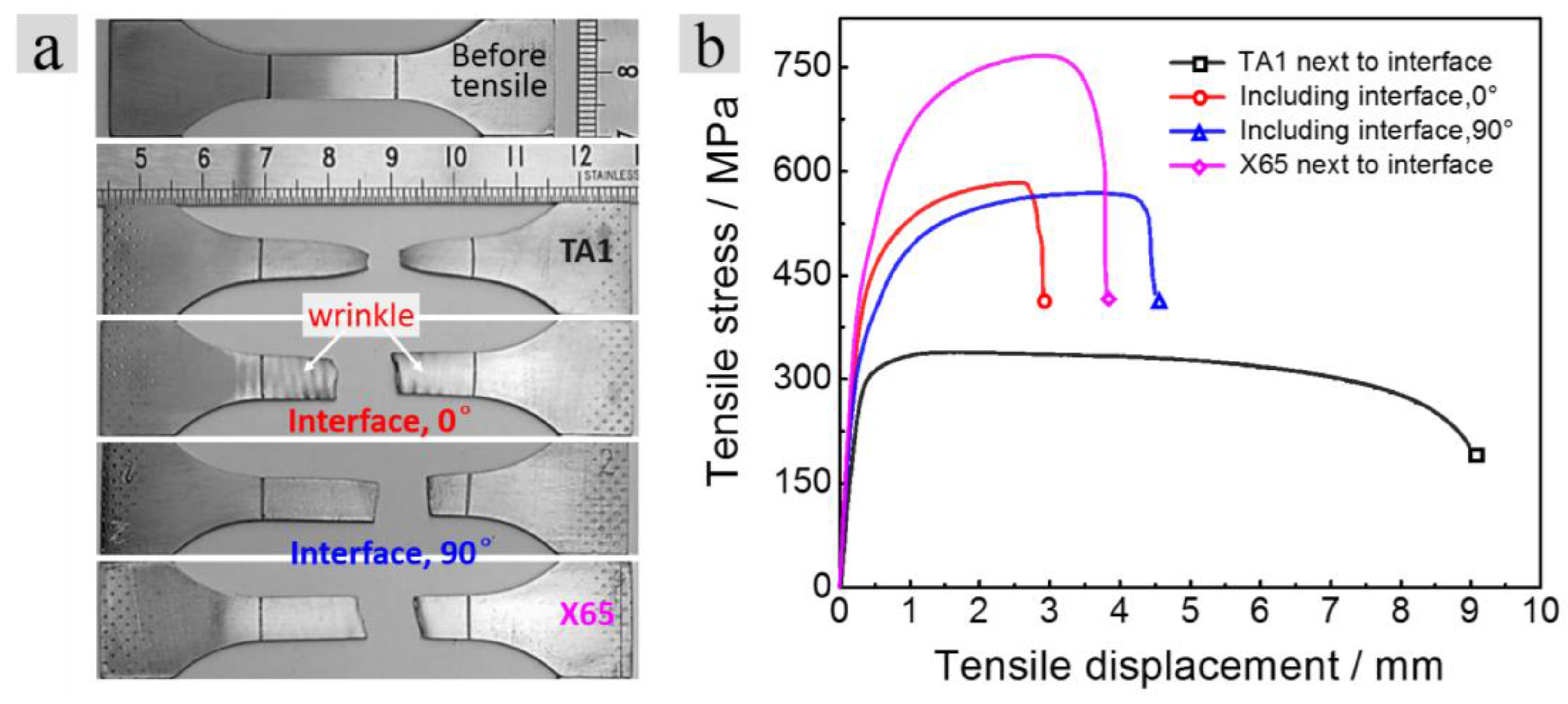
Figure 9.
Morphologies and element distribution of the tensile fracture when the tensile direction was parallel to the direction of detonation wave propagation: (a) fracture morphology; and (b–e) b–e zone of a.
Figure 9.
Morphologies and element distribution of the tensile fracture when the tensile direction was parallel to the direction of detonation wave propagation: (a) fracture morphology; and (b–e) b–e zone of a.

Figure 10.
Morphologies and element distribution of the tensile fracture when the tensile direction was perpendicular to the direction of detonation wave propagation: (a) fracture morphology; and (b–e) b–e zone of a.
Figure 10.
Morphologies and element distribution of the tensile fracture when the tensile direction was perpendicular to the direction of detonation wave propagation: (a) fracture morphology; and (b–e) b–e zone of a.
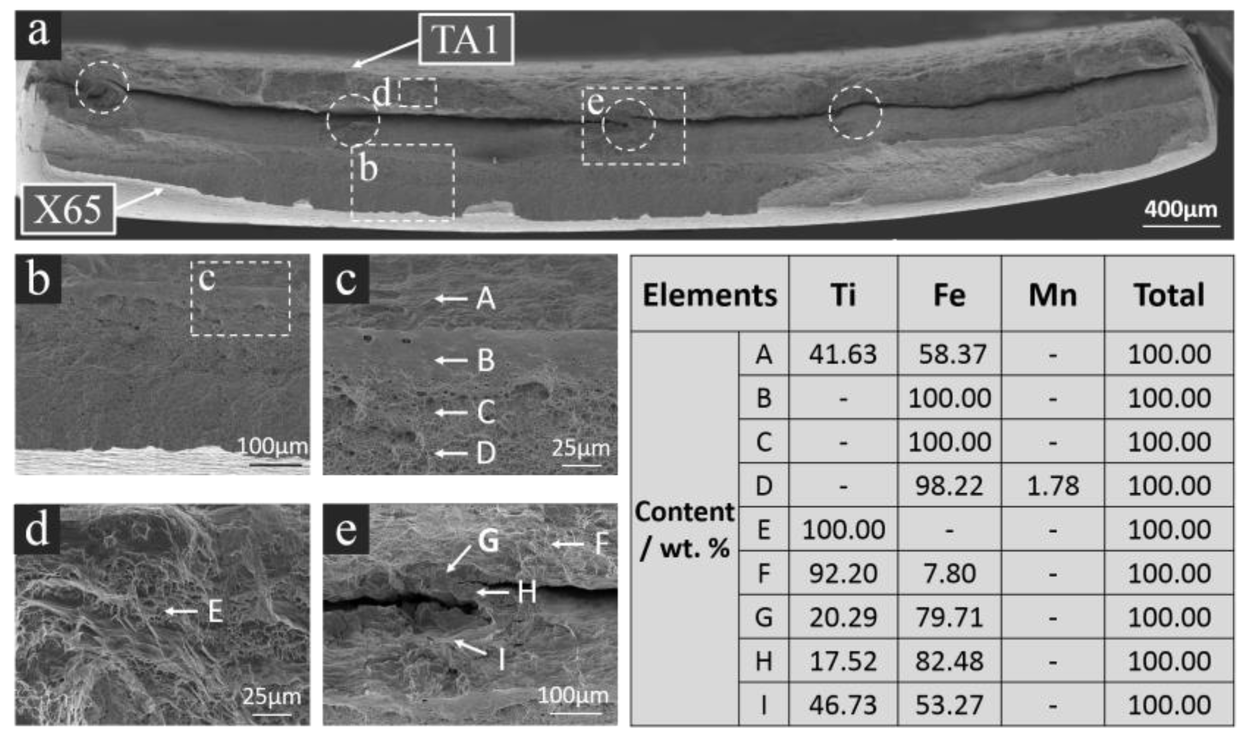
Figure 11.
Shear stress-displacement curves acquired from the compression-shear tests.

Figure 12.
Morphologies and element distributions of the shear fractures: (a) 90°; (b) 0°; (c) 180°; (d–f) element distributions of a, b and c.
Figure 12.
Morphologies and element distributions of the shear fractures: (a) 90°; (b) 0°; (c) 180°; (d–f) element distributions of a, b and c.

Table 1.
Chemical compositions of TA1 titanium (wt. %).
| Elements | C | Si | N | H | O | Fe | Ti |
|---|---|---|---|---|---|---|---|
| Content | ≤0.05 | ≤0.1 | ≤0.03 | ≤0.015 | ≤0.15 | ≤0.15 | Balance |
Table 2.
Chemical compositions of X65 steel (wt. %).
| Elements | C | Si | Mn | Ni | Cr | Cu | Mo | V | P | S | Fe |
|---|---|---|---|---|---|---|---|---|---|---|---|
| Content | 0.053 | 0.33 | 1.18 | 0.16 | 0.07 | 0.14 | 0.06 | 0.031 | 0.016 | ≤0.005 | Balance |
Table 3.
List of sample numbers in tensile tests (repeated three times).
| 90° | 0° | |
|---|---|---|
| TA1 adjacent to TA1/X65 interface | T1-1a, T1-1b, T1-1c | T1-2a, T1-2b, T1-2c |
| Region including TA1/X65 interface | T2-1a, T2-1b, T2-1c | T2-2a, T2-2b, T2-2c |
| X65 adjacent to TA1/X65 interface | T3-1a, T3-1b, T3-1c | T3-2a, T3-2b, T3-2c |
Table 4.
List of sample numbers in shear tests (repeated three times).
| Angles between Shear Direction and Detonation Wave Propagation Direction | 0° | 90° | 180° |
|---|---|---|---|
| Sample numbers | 0-B1, 0-B2, 0-B3 | 90-A1, 90-A2, 90-A3 | 180-C1, 180-C2, 180-C3 |
© 2018 by the authors. Licensee MDPI, Basel, Switzerland. This article is an open access article distributed under the terms and conditions of the Creative Commons Attribution (CC BY) license (http://creativecommons.org/licenses/by/4.0/).
Share and Cite
MDPI and ACS Style
Xie, M.-X.; Shang, X.-T.; Zhang, L.-J.; Bai, Q.-L.; Xu, T.-T. Interface Characteristic of Explosive-Welded and Hot-Rolled TA1/X65 Bimetallic Plate. Metals 2018, 8, 159. https://doi.org/10.3390/met8030159
AMA Style
Xie M-X, Shang X-T, Zhang L-J, Bai Q-L, Xu T-T. Interface Characteristic of Explosive-Welded and Hot-Rolled TA1/X65 Bimetallic Plate. Metals. 2018; 8(3):159. https://doi.org/10.3390/met8030159
Chicago/Turabian StyleXie, Miao-Xia, Xiang-Tao Shang, Lin-Jie Zhang, Qing-Lin Bai, and Ting-Ting Xu. 2018. "Interface Characteristic of Explosive-Welded and Hot-Rolled TA1/X65 Bimetallic Plate" Metals 8, no. 3: 159. https://doi.org/10.3390/met8030159
Note that from the first issue of 2016, this journal uses article numbers instead of page numbers. See further details here.