Article

Evaluation of Workability on the Microstructure and Mechanical Property of Modified 9Cr-2W Steel for Fuel Cladding by Cold Drawing Process and Intermediate Heat Treatment Condition

1
Department of Materials Engineering, Hanyang University, 55, Hanyangdaehak-ro, Sangnok-gu, Ansan-si 15588, Korea
2
Advanced Fuel Development Division, Korea Atomic Energy Research Institute, 34057 Daedeok-daero, Yuseong-gu, Daejeon 305-353, Korea
*
Author to whom correspondence should be addressed.
Metals 2018, 8(3), 193; https://doi.org/10.3390/met8030193
Submission received: 5 January 2018 / Revised: 13 March 2018 / Accepted: 14 March 2018 / Published: 18 March 2018

Abstract

:
In this study, we evaluated the cold drawing workability of two kinds of modified 9Cr-2W steel containing different contents of boron and nitrogen depending on the temperature and time of normalizing and tempering treatments. Using ring compression tests at room temperature, the effect of intermediate heat treatment condition on workability was investigated. It was found that the prior austenite grain size can be changed by the austenite transformation and that the grain size increases with increasing temperature during normalizing heat treatment. Alloy B and Alloy N showed different patterns after normalizing heat treatment. Alloy N had higher stress than Alloy B, and the reduction in alloy N increased while the reduction in alloy B decreased. Alloy B showed a larger number of initially formed cracks and a larger average crack length than Alloy N. Crack length and number increased proportionally in Alloy B as the stress increased. Alloy B had lower crack resistance than Alloy N due to boron segregation.

1. Introduction

A generation IV SFR (sodium-cooled fast reactor) uses liquid sodium as a coolant and creates nuclear fission using fast neutrons [1]. The main components of the SFR are the nuclear fuel assemblies and nuclear fuel cladding. Because irradiation with fast neutrons generates thermal creep and swelling, the nuclear fuel cladding tube needs to provide excellent swelling resistance, creep resistance and high temperature strength for long periods of time. To meet these requirements, the nuclear fuel cladding of sodium-cooled fast reactors is typically 9–12% Cr FM (ferritic martensitic) steel, which exhibits outstanding thermal conductivity, a low thermal expansion coefficient, and high resistance to void swelling [2].
Nonetheless, 9–12% Cr FM steels have a problem: their high temperature strength and creep characteristics deteriorate when they are subjected to high temperature for long periods of time. To improve mechanical properties such as creep strength and high temperature strength, the steel’s carbon content can be optimized by the addition of Mo and W, which are solid solution hardening elements, and Nb and V, which are elements that form carbides and nitrides [3]. Boron is also known to reduce the coarsening of (Cr, Fe)23C6 carbides and decrease minimum creep rate, which improves microstructure stability and improves the creep life of the material [4]. Nitrogen reacts to precipitation hardening elements such as V, Nb, and Cr to form fine nitrides (Nb, V)N and Cr2N. These nitrides effectively contribute to the high-temperature creep properties and improve microstructure stability due to their extremely high thermal stability [5].
In previous studies, nuclear fuel cladding has been fabricated using several procedures. These include VIM (vacuum induction melting), hot working such as hot forging and hot extrusion, and cold working such as cold pilgering, which reduces the thickness and outer diameter by more than 90%, and several cold drawing methods with intermediate heat treatment. After fabrication with the desired specifications, the manufactured nuclear fuel cladding tube is finally normalized and tempered. Some studies have shown that when boron and nitrogen are added to improve creep characteristics and mechanical properties, the additives also affect the material’s workability, depending on content and heat treatment [6,7].
9–12% Cr FM steel was used to conduct a SIMS (secondary ion mass spectrometry) analysis of the distribution of boron at grain boundaries caused by the effects of normalizing and tempering [8]. The study on the high temperature ductility was carried out since the surface crack and corner crack occurred in the continuous casting process of boron added steel [9]. Boron has been reported to change its mechanical properties depending on the cooling rate and the heat treatment temperature [10]. These indicate that boron precipitates as compounds such as BN and (Cr, Fe)23(B, C)6 at grain boundaries, weakening the grain boundary and reducing high temperature ductility [11].
In this study, we evaluated the cold drawing workability of two kinds of modified 9Cr-2W steel with different contents of boron and nitrogen, depending on normalizing and tempering temperature and time. Ring compression testing at room temperature was used to investigate the effect of heat treatment on workability.

2. Materials and Methods

The chemical compositions of the two different kinds of modified 9Cr-2W steel, designated Alloy B and Alloy N, are shown in Table 1.
The modified 9Cr-2W steel ingot was melted in VIM (vacuum induction melting, Posco, Pohang, Korea) and then hot-forged at 1170 °C to form rods. The fabricated modified 9Cr-2W steel rods were processed into billets and hot extruded at 1170 °C to produce extruded pipes with a 46 mm outer diameter and 3.5 mm thickness. The manufactured mother tube was finally fabricated into a drawn tube with a 19.05 mm outer diameter and 1.15 mm thickness by a cold drawing process.
The drawn tubes were sealed in quartz tubes in an atmosphere of argon gas and then normalized at 1038–1180 °C for 6 and 30 min, followed by air cooling to room temperature. A tempering treatment of the normalized specimens was carried out at 760 °C for 40 min, followed by air cooling to room temperature. The heat treatment conditions of the modified 9Cr-2W steel are shown in Table 2. In order to observe the microstructure produced by the particular heat treatment condition, the specimens were observed by optical microscope after etching with a mixed solution of HF (hydrofluoric acid):HNO3 (nitric acid):H2O (distilled water) = 2:3:95.
In order to evaluate the mechanical properties and workability of the modified 9Cr-2W steel as a result of the particular heat treatment conditions, ring compression testing was performed at room temperature using an INSTRON-3367.
The cold pilgering and cold drawing induce tensile stress in the axial direction, and compressive stress in the circumferential direction. Ring compression tests have also been conducted to evaluate the workability of zirconium alloys after cold pilgering [12]. In this test, compressive stress after cold working was evaluated. The compression test specimens were compressed at a rate of 1 mm/min for cladding with a 19.05 mm outer diameter and 1.15 mm thickness and 10 mm length. We performed ring compression tests at room temperature based on the heat treatment conditions and used a stereoscope to observe the shape of cracks produced by the respective heat treatment conditions.
In order to investigate the change in hardness produced by the various heat treatment conditions, the Vickers hardness test was performed. The results were measured 12 times for each specimen under a load of 500 g, the minimum and maximum values were excluded, and then standard deviation and mean were evaluated.

3. Results

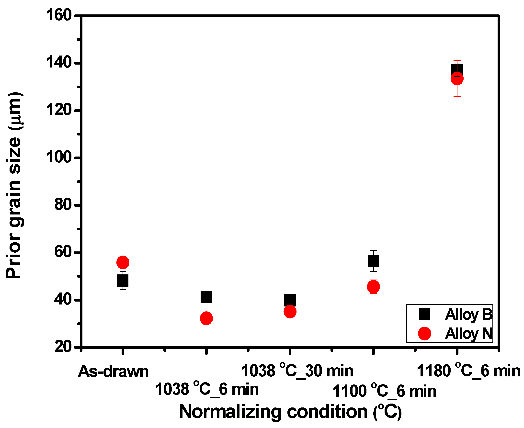
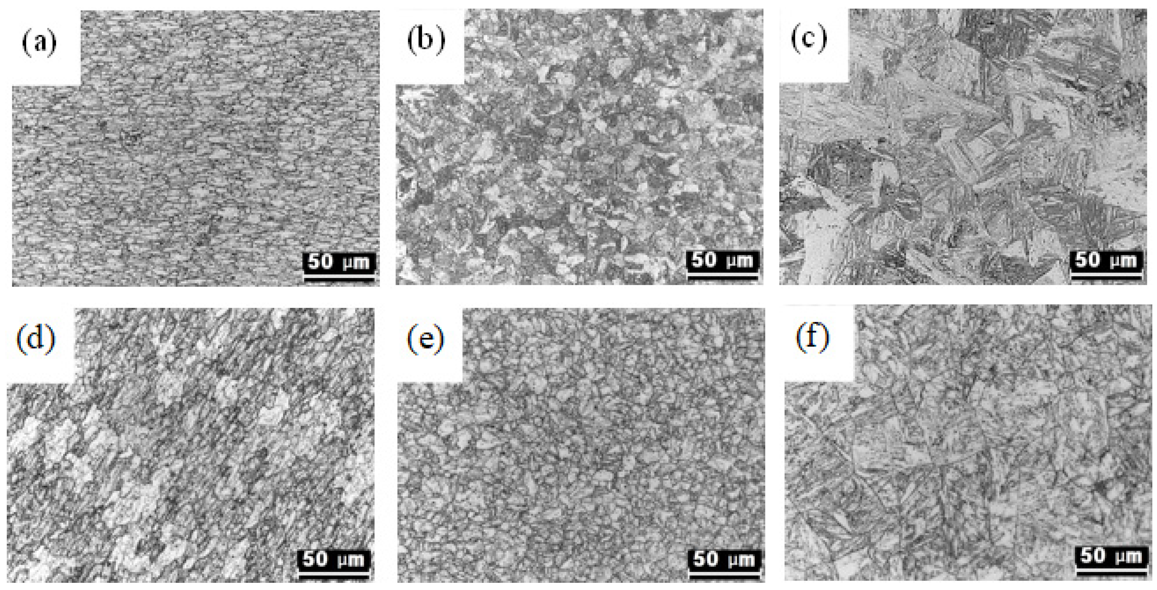
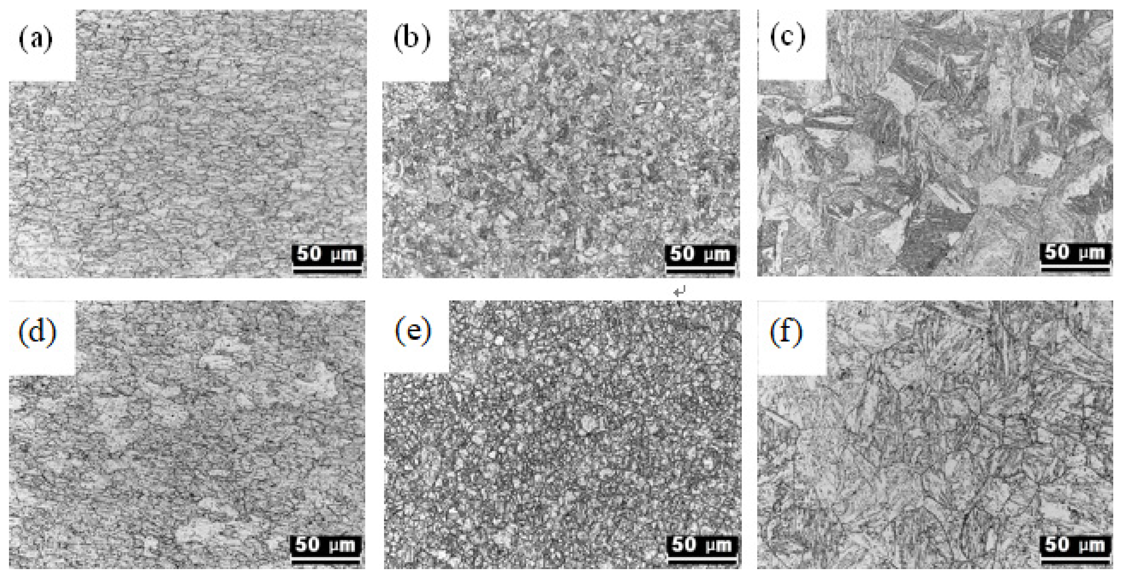
3.1. Changes in Microstructure According to Heat Treatment Conditions

Figure 1 and Figure 2 show photographs of Alloy B and Alloy N following heat treatment, respectively. The pilgering and drawing processes created an elongated grain boundary in the drawing direction in the as-drawn specimens.
On the other hand, the elongated grain boundary disappears in the normalized condition. Figure 2d indicates the tempering heat condition after treatment at 760 °C for 40 min without a normalizing heat treatment.
Figure 3 shows the effect on austenite grain size for Alloy B and Alloy N, based on normalizing conditions. In the initial state, as-drawn Alloy B and Alloy N have an austenite grain size of 48 and 55 μm, respectively. In particular, at 1180 °C the prior austenite grain size increased to more than twice the size of the prior austenite grain at 1038 °C.

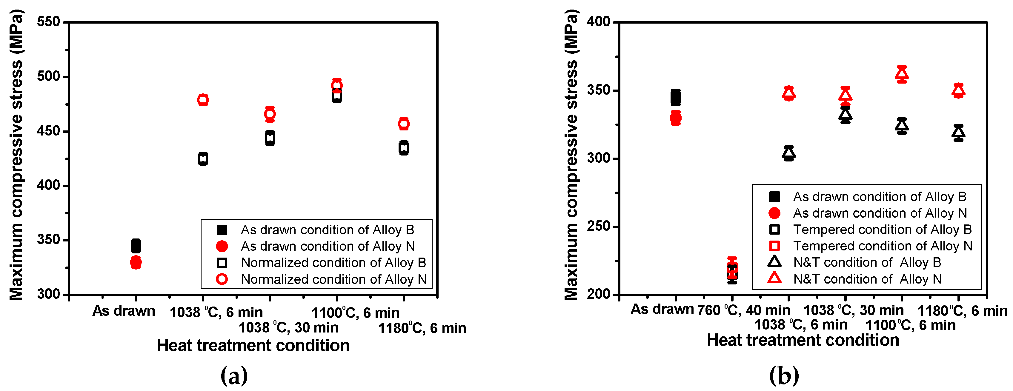
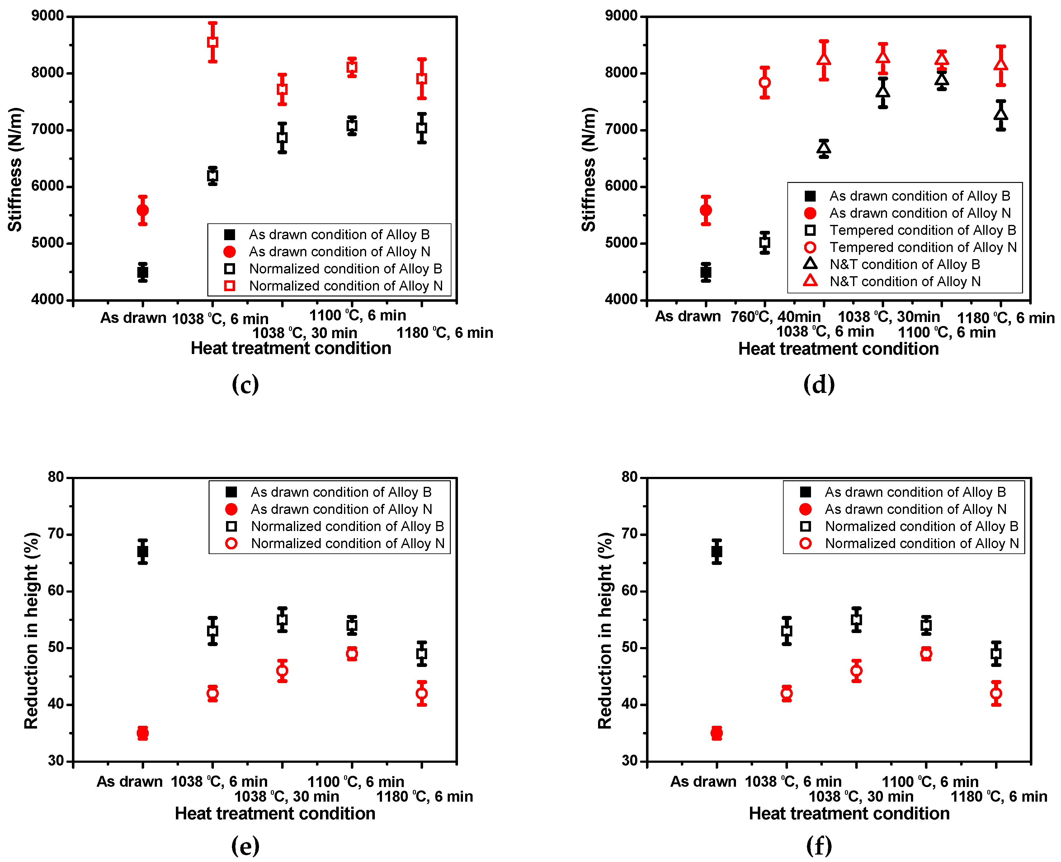
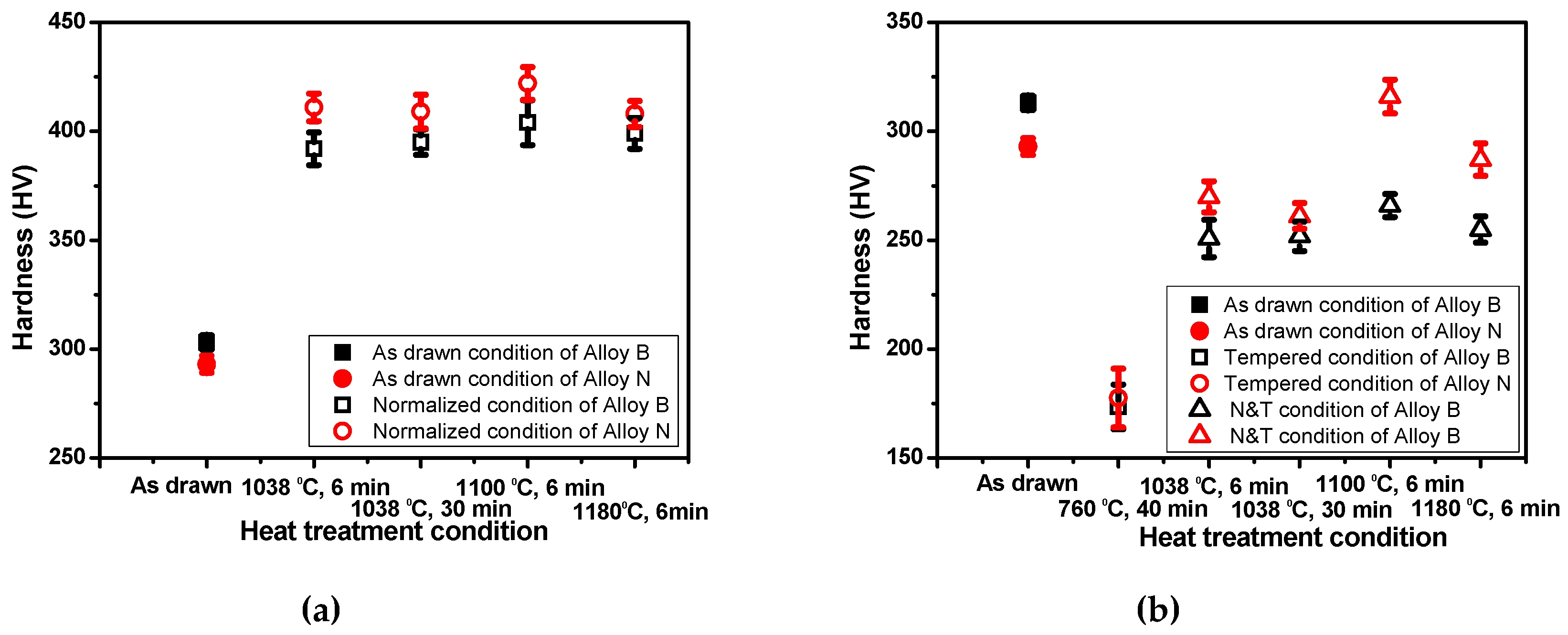
3.2. Effect of Heat Treatment Conditions on Mechanical Properties

Figure 4 shows a specimen (Alloy B) normalized at 1038 °C for 6 min. A ring compression test was conducted at room temperature and the results are represented in the schematic diagram. The ring compression test was performed by pressing the sample in the cladding tube with a plate fixed top and bottom at a constant strain rate. The cladding tube gradually turns into an ellipse, because the applied stress deforms the cladding tube as the axial load on the cladding tube increases. The aspects of the cracks at maximum compressive stress were found to be different for the normalizing condition, as compared to the tempering condition. In the normalizing condition, the generated cracks grew and then failed due to interactions, as the stress was increased.
However, with the tempering condition, many cracks tended to occur; however, unlike the normalizing condition case, when the stress increased, the length and width of the cracks increased, but the cracks did not interact with crack growth and then failed due to interaction as the stress was increased.
Figure 5 shows the results of maximum compressive strength and stiffness for ring compression testing at room temperature based on heat treatment conditions. The results for the as-drawn steels show that the maximum compressive stress of Alloy B is higher than that of Alloy N. Since the prior austenite grain size of alloy N is larger than that of Alloy B, the maximum compressive stress of Alloy N has a smaller value in the Hall–Petch equation. The stress in Alloy N has a higher value than that of Alloy B after normalizing.
Both alloys were normalized by heat treatment, and below 1100 °C the prior austenite grain size was less than that of the as-drawn samples. The prior austenite grain sizes increased but the stress was higher than the stress of the as-drawn samples after heat treatment above 1100 °C.
Overall, the stiffness of Alloy N was found to be higher than that of Alloy B, and Alloy N had a constant stiffness after heat treatment. On the other hand, Alloy B exhibited a higher stiffness than that of as-drawn B when it was annealed at 760 °C for 40 min.
Normalized specimens of the two alloys were tempered at 760 °C for 40 min and had high stiffness. Therefore, Alloy N was determined to have high resistance to deformation in response to an applied force.
Comparing the reduction in height of the two alloys, the reduction in height of as-drawn B was higher than that of as-drawn N. The reduction in height of the two alloys was different before and after the normalizing heat treatment. In the case of Alloy B, the reduction in height decreased as the normalizing temperature increased.
Figure 6 shows the hardness results based on heat treatment. These results show a tendency similar to that for stress.
Figure 7 shows photographs of cracks and the number and length of cracks for the as-drawn conditions. The crack lengths and the numbers of cracks were compared in order to determine the effect on workability induced by crack resistance during fuel cladding manufacture. Cracks were formed in Alloy B when stress reached 241 MPa, while, in alloy N, cracks were generated when stress reached 310 MPa.

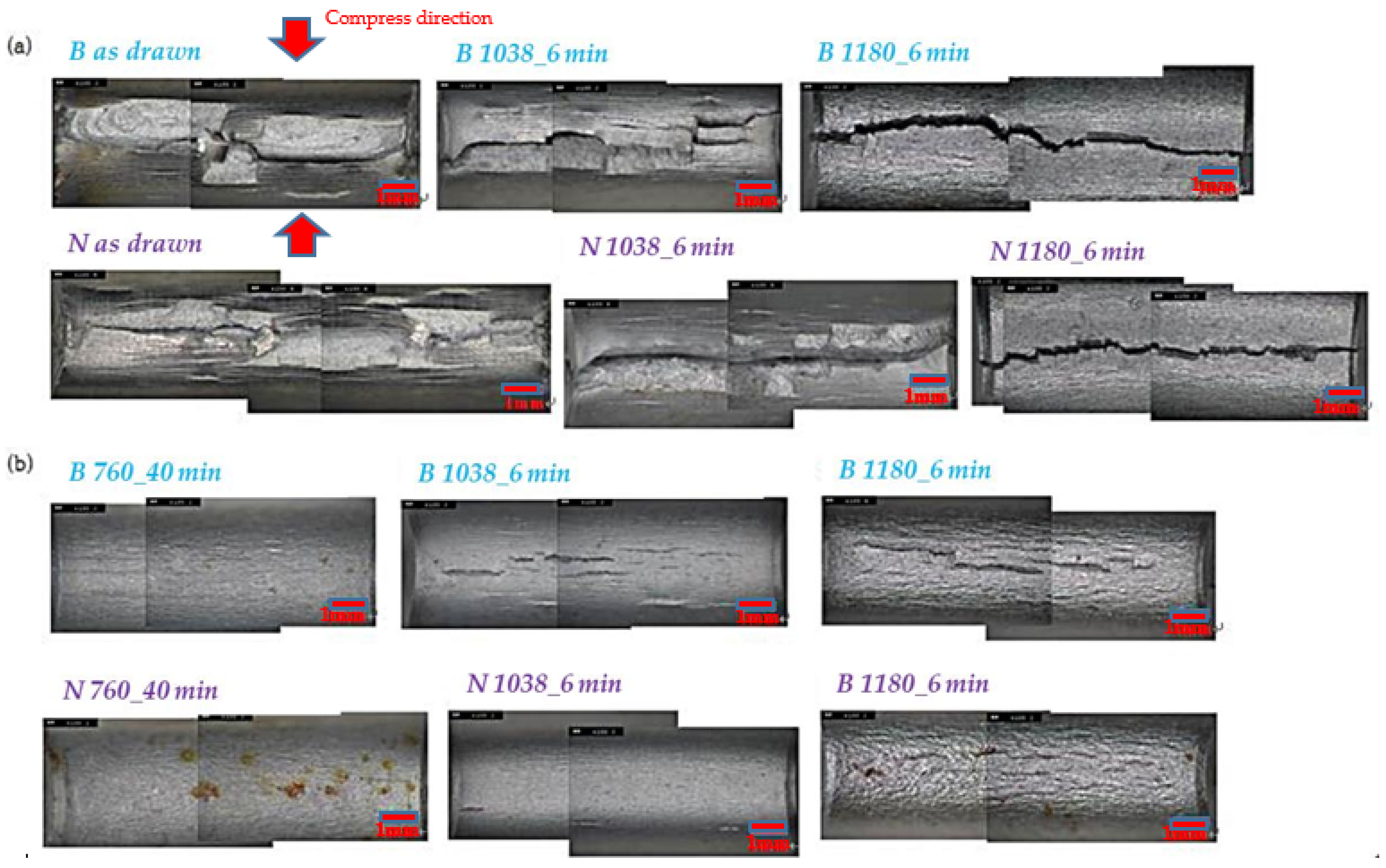
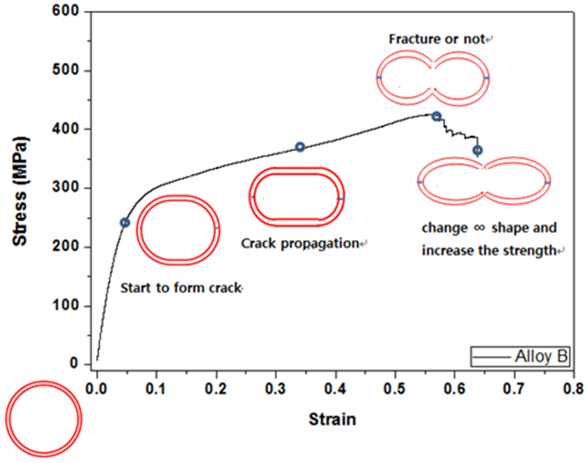
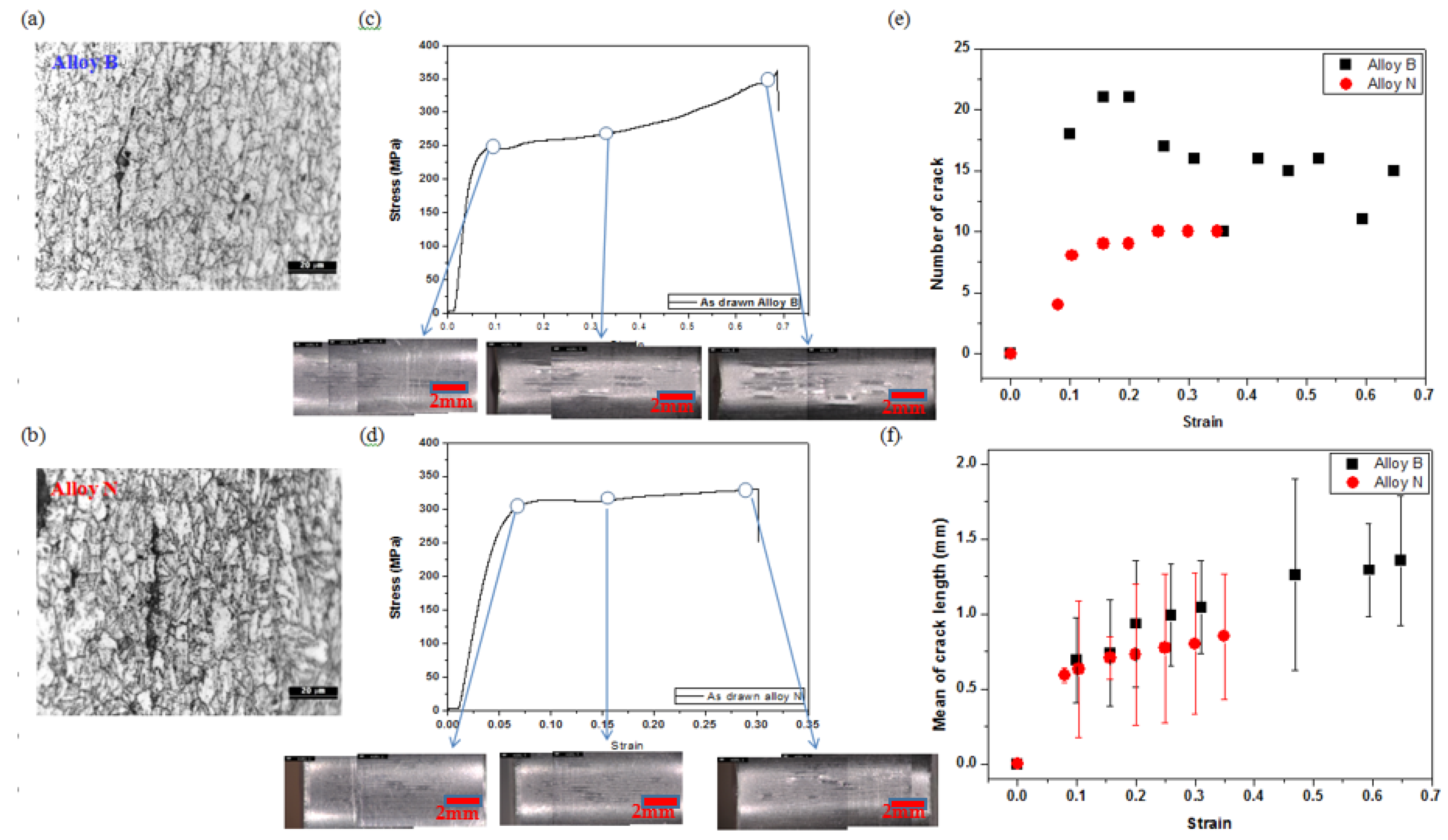
3.3. Crack Formation and Observation

Figure 8 shows cracks that were observed after carrying out compression testing at room temperature, based on heat treatment conditions. Between temperatures of 1038 to 1100 °C, multiple cracks were generated when the maximum compressive stress was reached, and when the maximum tensile stress was applied in the longitudinal direction, the existing cracks were connected and formed into a shape like stair steps. As the tensile stress increased in the axial direction in the center part in the specimen at 1180 °C, the sample seemed to be fractured by an existing single crack. Multiple cracks existed without connecting in the tempering condition. The tempering heat treatment changed the sample from a martensitic structure with brittleness to a tempered martensitic structure with increasing ductility and, following the transition, the cracks were different in appearance.

4. Discussion

This study investigated the mechanical properties of cladding tubes fabricated with two types of alloy, Alloy B and Alloy N, and evaluated the effects of normalizing and tempering heat treatments on the workability of the tubes, which is required for manufacturing cladding tube. In Figure 1 and Figure 2, the as-drawn specimen has an elongated grain boundary in the drawing direction due to deformation by drawing and pilgering process. On the other hand, the deformed microstructure was transformed into an austenitic structure by heating at the AC1 (the temperature at which the α⟶γ transformation commences on heating) transformation point or higher in the normalized condition [13]. The deformed structure disappears during austenitization, and lath martensite forms with a high dislocation density in the PAG (prior austenite grain) on cooling [14].
The PAGs are divided into packet boundaries parallel to a group of laths with the same habit plane, and each packet boundary is further subdivided into block boundaries with the same orientation as the lath group [15]. The lath and packet are parallel to the {111} plane of the austenite and have K-S orientation relationship [15,16]. In a packet, there are six variants with different direction parallel relationships on the same conjugate parallel close-packed plane (e.g., (111)γ//(011)α’) [15,16].
The tempering heat treatment does not cause phase transformation, so some deformed microstructure remains. A typical tempered martensitic structure is produced by the tempering condition after normalizing. There is recrystallization during the tempering heat treatment, and the strength decreases and the ductility increases due to dislocation recovery, but the previous austenite grain size is not affected [17]. The change of prior austenite grain boundary size is related to normalizing temperature. When the as-drawn specimens were normalized at 1038 °C, the austenite transformation resulted in recrystallization of the deformed microstructure and an increase in nucleation sites, resulting in smaller grain sizes. At a normalizing temperature above 1100 °C, the grain sizes increased because the growth rate of the grain was faster than the rate at which the nucleation sites occurred. As the normalizing temperature increases, compressive stress also increases.
Studies have also shown that strength and hardness of 9–12% Cr FM steels increase with increasing normalizing temperature [18,19]. The formation of fresh martensite increase and dissolution of precipitates such as (Cr, Fe)23(B, C)6 were found to be enhanced with an increase in normalizing temperature [19,20]. After the precipitate containing Cr, C and B atoms dissolves, it spreads to the solid solution and increases the concentration of the solute in solid solution, resulting in a more pronounced solid solution hardening effect and improved hardness and strength. On the other hand, it is well known that (Nb and V) (C and N) precipitates with high thermal stability exist without dissolution up to 1200 °C, and the growth rate is not fast [5,18].
When the as-drawn conditions were tempered at 760 °C for 40 min, stress was reduced because the dislocation density decreased, and pronounced sub-grain formation across the lath boundaries due to dislocation recovery [13]. Other factor is the decrease of the solid solution hardening effect due to the formation of precipitates.
Studies have used APT (atom probe tomography, CEA, Grenoble, France) to analyze the distribution of solute atoms in the formed atmospheres around dislocations and segregation of solute atoms at the grain boundary during heat treatment [21,22]. According to Li et al. [23], distribution of C and Cr in the PAGB and matrix was analyzed by using APT in the quenched specimen. The C was segregated in the M-M boundary (M is Martensite) but Cr was uniformly distributed in the matrix [23]. During the tempering heat treatment, the concentrations of Cr, Mo and V decrease in the matrix [8] and there are also many small regions with less concentrated enrichment, which is considered to be related to the Cottrell atmospheres of C containing a small amount of Cr atom at individual dislocation [22].
Precipitates can be found at grain boundaries during tempering. The nucleation of precipitations at grain boundaries is heterogeneous, which is thermodynamically advantageous due to the reduction in the energy barrier for nucleation [24]. Nucleation at grain boundaries is especially favored when the chemical driving force is low and, simultaneously, the ratio between the grain boundary energy and that of the “nucleus/bulk” interface is high [24]. Then, the self-diffusion coefficient at any grain boundary is generally higher than that in the volume; this allows the solute atoms to rapidly migrate towards any new phase nucleus within the grain boundary [24]. In addition, as the dislocation density decreases, the Cottrell atmospheres of Cr, C and B at the dislocation are separated from the dislocation and then diffuse into regions where the Cr, B and C atoms are uniformly distributed in the PAGB [22,25,26]. When the solute Cr and C atoms are saturated at the grain boundary, particle nuclei form [24].
Stiffness is the rigidity of an object against deformation in response to an applied force. This resistance is a property of the structure or a component of the structure, and hence it is dependent upon the various physical dimensions which describe that component. For example, for an element in tension or compression, the axial stiffness is
k   =   A E L
where A is the cross-section area, E is the (tensile or compression) elastic modulus (or Young’s modulus), and L is the length of the element.
In general, the failure mechanism in low carbon martensitic steels is known as void growth [27]. As the local strain increase in elastic regions, a microvoid is formed in the grain boundary.
Cracks are generated because the stress applied to the material changes elastic regions into plastic regions during ring compression test at room temperature. These are thought to be formed by the accumulation of many small cracks in a direction that is tangential to the inner surface. It appears that more than 10% tensile strain is sufficient to produce the occurrence of cracks [28]. This crack growths until it approaches the outer annulus, where a change in failure path occurs as the process approaches final failure [28]. Along the shear plane, the final failure and shear lip occur depending on ductility, the mount of shear lip varies, strain rate and temperature [28].
The grain boundary between boron and steel is known to occur due to equilibrium and non-equilibrium segregation [29]. Equilibrium grain boundary segregation occurs with the movement of solute atoms from the matrix to grain boundaries and free surfaces. The driving force for the equilibrium segregation is the reduction in the grain boundary free energy. NGS (non-equilibrium grain boundary segregation) occurs during cooling from high temperatures when mobile vacancy-solute complexes diffuse down vacancy gradients towards vacancy sinks [30]. The NGS mechanism depends on the formation of sufficient quantities of vacancy-solute complexes. It has been widely accepted that the NGS of boron in steel is the dominating process [31].
Since the vacancy concentration also increases as the normalizing temperature increases, the vacancy-solute complexes increase and the segregation of boron often occurs at the grain boundary. Segregation of boron may weaken the grain boundary bonding force. Therefore, the reduction in height is decreased by the segregation of boron, and it decreases especially sharply at 1180 °C. In the case of Alloy N, the reduction in height increased as the normalizing temperature increased. During the normalizing heat treatment, carbide is solubilized in the matrix and has a low fraction of precipitate, which decreases the interaction between carbon and dislocations. As a consequence, the reduction in height increases as the normalizing temperature increases.
When as-drawn Alloy B samples were tempered at 760 °C for 40 min, the decrease in height reduction was attributed to the segregation of boron. Some studies have analyzed the tempering heat treatment by APT (atom probe tomography) [8]. The APT results show that the concentrations of Cr, Mo, V and Mn in the matrix decrease, and then Nb, B and N are depleted from the matrix. It is noteworthy that the M23C6 precipitate at a PAGB contains a very high concentration of boron [8]. Segregation were analyzed from the view point of grain boundary characteristics by using EBSD (electron back-scattered diffraction) [32]. It is well known that the segregation is thermodynamically preferential to occur at high energy boundaries such as high angle random boundaries (Prior austenite grain boundary and packet boundary) [33]. From the results of APT and EBSD, it can be seen that segregation occurs along the high angle grain boundary.
Comparing the two alloys, a larger number of cracks initially formed in Alloy B, and the cracks had a larger average length than those in Alloy N. The cracks in Alloy B increased proportionally as the stress increased. Alloy B had a lower crack resistance than Alloy N. The reason for the low crack resistance of Alloy B is considered to be weakening of grain boundary due to segregation of excess boron.

5. Conclusions

This study investigated the mechanical properties of cladding tubes fabricated with two types of alloy, Alloy B and Alloy N, and evaluated the effects of normalizing and tempering heat treatments on the workability of the tubes, which is required for manufacturing cladding tube. The difference in stress of the as-drawn alloys was indicated by the difference in prior austenite grain size. The prior austenite grain size can be changed by the austenite transformation, and the grain size was found to increase with increasing normalizing temperature in the normalizing heat treatment process. The stiffness of Alloy N was determined to be higher than that of Alloy B, and Alloy N had a constant stiffness after heat treatment. On the other hand, Alloy B had a higher stiffness than that of as-drawn B when it was annealed at 760 °C for 40 min.
Normalized specimens of the two alloys were tempered at 760 °C for 40 min and exhibited high stiffness. Alloy N was determined to have high resistance to deformation in response to an applied force. Comparing the two alloys, Alloy B showed a larger number of initially formed cracks and a larger average crack length, than Alloy N. Cracking in Alloy B increased proportionally as the stress increased, and Alloy B had a lower crack resistance than Alloy N. The reason for the low crack resistance of Alloy B is considered to be the weakening of the grain boundary due to the segregation of excess boron.

Acknowledgments

This work was done by the ‘Sodium-cooled Fast Reactor Cladding Development Project’ supported by the National Nuclear R & D program through the sodium-cooled fast reactor development agency funded by the Ministry of Science & Information, Communication and Technology.

Author Contributions

Jun-Hwhan Kim designed the experiments; Jong-Ryoul Kim contributed to the discussion of the results; Hyeong-Min Heo performed the experiments and wrote the paper; Sung-Ho Kim supervised the project.

Conflicts of Interest

The authors declare no conflict of interest.

References

  1. Kim, J.H.; Heo, H.M.; Baek, J.H.; Kim, S.H. Evaluation of the mechanical properties of a HT9 fuel cladding tube for a sodium-cooled fast reactor. J. Korean Inst. Met. Mater. 2013, 51, 25–31. [Google Scholar] [CrossRef]
  2. Klueh, R.L. Elevated-temperature Ferritic and Martensitic Steels and Their Application to Future. Int. Mater. Rev. 2005, 50, 287–310. [Google Scholar] [CrossRef]
  3. Paul, V.T.; Saroja, S.; Vijayalakshmi, M. Microstructural stability of modified 9Cr-1Mo steel during long term exposures at elevated temperatures. J. Nucl. Mater. 2008, 378, 273–281. [Google Scholar] [CrossRef]
  4. Abe, F. Effect of Boron on Microstructure and Creep Strength of Advanced Ferritic Power Plant Steels. Procedia Eng. 2011, 10, 94–99. [Google Scholar] [CrossRef]
  5. Ryu, W.S.; Kim, S.H. Thermal treatment improving creep properties of nitrogen-added Mod. 9Cr-1Mo steels. Trans. Indian Inst. Met. 2010, 63, 111–115. [Google Scholar] [CrossRef]
  6. Lu, Y. Effect of Boron on Microstructure and Mechanical Properties of Low Carbon Microalloyed Steels. Master’s Thesis, McGil University, Montreal, QC, Canada, 2007. [Google Scholar]
  7. Kim, Y.H.; Kim, K.Y.; Lee, Y.D. Nitrogen-Alloyed, Metastable Austenitic Stainless Steel for Automotive Structural Applications. Mater. Manuf. Process. 2004, 19, 51–59. [Google Scholar] [CrossRef]
  8. Liu, F.; Fors, D.H.R.; Golpayegani, A.; Andrén, H.O.; Wahnström, G. Effect of boron on carbide coarsening at 873 K in 9 to 12 pct chromium steels. Metall. Mater. Trans. A Phys. Metall. Mater. Sci. 2012, 43, 4053–4062. [Google Scholar] [CrossRef]
  9. Cho, K.C.; Koo, Y.M.; Park, J.K. Effect of cooling rate on the hot ductility of boron bearing steel during continuous casting. J. Korean Inst. Met. Mater. 2008, 46, 329–337. [Google Scholar]
  10. Lim, J.H.; Kim, J.S.; Park, B.H.; Lee, J.H.; Choi, J.M. Effects of Heat Treatment on the Micro-structures and the Mechanical Properties of 0.002% Boron-added Low Carbon Steel. Korean J. Mater. Res. 2011, 21, 303–308. [Google Scholar] [CrossRef]
  11. Yamamoto, K.; Susuki, H.G.; Oono, Y.; Noda, N.; Inoue, T. Formation mechanism and prevention method of facial cracks of continuously cast steel slabs containing boron. Tetsu-to-Hagane 1987, 73, 115–122. [Google Scholar] [CrossRef]
  12. Abe, H.; Furugen, M. Evaluation Method of Workability in Cold Pilgering of Zirconium-based Alloy Tube. Mater. Trans. 2010, 51, 1200–1205. [Google Scholar] [CrossRef]
  13. Klueh, R.L.; Harries, D.R. High-Chromium Ferritic and Martensitic Steels for Nuclear Applications; ASTM International: West Conshohocken, PA, USA, 2001; ISBN 978-0-8031-2090-7. [Google Scholar]
  14. Saroja, S.; Vijayalakshmi, M.; Raghunathan, V.S. Influence of cooling rates on the transformation behaviour of 9Cr-1 Mo-O.07C steel. J. Mater. Sci. 1992, 27, 2389–2396. [Google Scholar] [CrossRef]
  15. Morito, S.; Huang, X.; Furuhara, T.; Maki, T.; Hansen, N. The morphology and crystallography of lath martensite in Fe-C alloy steels. Acta Mater. 2006, 54, 5323–5331. [Google Scholar] [CrossRef]
  16. Maki, T. Morphology and substructure of martensite in steels. Anal. Tech. 2012, 2, 34–58. [Google Scholar] [CrossRef]
  17. Barbadikar, D.R.; Deshmukh, G.S.; Maddi, L.; Laha, K.; Parameswaran, P.; Ballal, A.R.; Peshwe, D.R.; Paretkar, R.K.; Nandagopal, M.; Mathew, M.D. Effect of normalizing and tempering temperatures on microstructure and mechanical properties of P92 steel. Int. J. Press. Vessel. Pip. 2015, 132–133, 97–105. [Google Scholar] [CrossRef]
  18. Wang, S.S.; Peng, D.L.; Chang, L.; Hui, X.D. Enhanced mechanical properties induced by refined heat treatment for 9Cr-0.5Mo-1.8W martensitic heat resistant steel. Mater. Des. 2013, 50, 174–180. [Google Scholar] [CrossRef]
  19. Yan, P.; Liu, Z.; Bao, H.; Weng, Y.; Liu, W. Effect of tempering temperature on the toughness of 9Cr-3W-3Co martensitic heat resistant steel. Mater. Des. 2014, 54, 874–879. [Google Scholar] [CrossRef]
  20. Saini, N.; Pandey, C.; Mahapatra, M.M. Characterization and evaluation of mechanical properties of CSEF P92 steel for varying normalizing temperature. Mater. Sci. Eng. A 2017, 688, 250–261. [Google Scholar] [CrossRef]
  21. Miller, M.K. Atom probe tomography characterization of solute segregation to dislocations. Microsc. Res. Tech. 2006, 69, 359–365. [Google Scholar] [CrossRef] [PubMed]
  22. Liu, Q.; Zhao, S. Cu precipitation on dislocation and interface in quench-aged steel. MRS Commun. 2012, 2, 127–132. [Google Scholar] [CrossRef]
  23. Li, Y.J.; Ponge, D.; Choi, P.; Raabe, D. Atomic scale investigation of non-equilibrium segregation of boron in a quenched Mo-free martensitic steel. Ultramicroscopy 2015, 159, 240–247. [Google Scholar] [CrossRef] [PubMed]
  24. Priester, L. Grain Boundaries: From Theory to Engineering; Wang, Z.M., Ed.; Springer: Dordrecht, The Netherlands, 2013; ISBN 978-94-007-4968-9. [Google Scholar]
  25. Love, G.R. Dislocation Pipe Diffusion. Acta Metall. 1964, 12, 731–737. [Google Scholar] [CrossRef]
  26. Heo, H.M.; Jeong, E.H.; Kim, S.H.; Kim, J.R. Comparison between effect of B and N on the microstructure of modified 9Cr-2W steel during aging and creep. Mater. Sci. Eng. A 2016, 670, 106–111. [Google Scholar] [CrossRef]
  27. Du, C. Micro-Plasticity Characterization of Martensite, Ferrite, and Dual-Phase Steel. Ph.D. Thesis, Technische Universiteit Eindhoven, Eindhoven, The Netherlands, 2016. [Google Scholar]
  28. Yamada, R.; Suzuki, M.; Harayama, Y. Application of finite element method to ring compression test. Nucl. Eng. Des. 1977, 44, 75–85. [Google Scholar] [CrossRef]
  29. Liu, A.F. Mechanics and Mechanisms of Fracture: An Introduction; ASM International: West Conshohocken, PA, USA, 2005; ISBN 0871708027. [Google Scholar]
  30. Mun, D.J.; Shin, E.J.; Koo, Y.M. A study on the behavior of boron distribution in low carbon steel by particle tracking autoradiography. Nucl. Eng. Technol. 2011, 43, 1–6. [Google Scholar] [CrossRef]
  31. Williams, T.M.; Stoneham, A.M.; Harries, D.R. The segregation of boron to grain boundaries in solution-treated Type 316 austenitic stainless steel. Met. Sci. 1976, 10, 14–19. [Google Scholar] [CrossRef]
  32. Park, S.G.; Lee, K.H.; Kim, M.C.; Lee, B.S. Effects of boundary characteristics on resistance to temper embrittlement and segregation behavior of Ni–Cr–Mo low alloy steel. Mater. Sci. Eng. A 2013, 561, 277–284. [Google Scholar] [CrossRef]
  33. Militzer, M.; Wieting, J. Segregation mechanisms of temper embrittlement. Acta Metall. 1989, 37, 2585–2593. [Google Scholar] [CrossRef]
Figure 1. Optical micrographs of Alloy B for different heat treatment conditions: (a) as-drawn; (b) normalized at 1038 °C for 30 min; (c) normalized at 1180 °C for 6 min; (d) tempered at 760 °C for 40 min after as-drawn; (e) tempered at 760 for 40 min after normalized at 1038 °C for 30 min and (f) tempered at 760 for 40 min after normalized at 1180 °C for 6 min.
Metals 08 00193 g001
Figure 2. Optical micrographs of Alloy N for different heat treatment conditions: (a) as-drawn; (b) normalized at 1038 °C for 30 min; (c) normalized at 1180 °C for 6 min; (d) tempered at 760 °C for 40 min after as-drawn; (e) tempered at 760 for 40 min after normalized at 1038 °C for 30 min and (f) tempered at 760 for 40 min after normalized at 1180 °C for 6 min.
Metals 08 00193 g002
Figure 3. Variation in prior austenite grain size of Alloy B and Alloy N with different normalizing conditions.
Metals 08 00193 g003
Figure 4. A Schematic diagram showing the effect of strain on the shape of the specimen (1038 °C, 6 min).
Metals 08 00193 g004
Figure 5. Results of ring compression test with heat treatment condition for Alloy B and Alloy N. X axis represents the temperature and time of as-drawn, normalized condition and tempered condition: (a) maximum compressive stress of the normalized condition; (b) maximum compressive stress of the tempered condition after normalized condition; (c) stiffness of the normalized condition; (d) stiffness of the of the tempered condition after normalized condition; (e) reduction in height of the normalized condition and (f) reduction in height of the tempered condition after normalized condition.
Metals 08 00193 g005aMetals 08 00193 g005b
Figure 6. Results of hardness testing with heat treatment condition for Alloy B and Alloy N. X axis represents the temperature and time of as drawn, normalized condition and tempered condition: (a) normalized condition and (b) tempered condition.
Metals 08 00193 g006
Figure 7. Observation of cracks by optical microscope image (a,b); stress–strain curve and stereo scope image (c,d); (e) number of cracks depending on strain. (f) mean of crack length depending on strain.
Metals 08 00193 g007
Figure 8. Observation of cracking with heat treatment: (a) normalizing condition; and (b) tempering condition (760 °C, 40 min after normalizing).
Metals 08 00193 g008
Table 1. Chemical compositions of the modified 9Cr-2W steels (wt %).
AlloyCCrWNBFe
Alloy B0.078.891.9340.020.013Bal.
Alloy N0.0639.092.0190.07670.004Bal.
Table 2. Heat treatment conditions of the modified 9Cr-2W steels.
NormalizingTempering
1038 °C, 6 min760 °C, 40 min
1038 °C, 30 min
1100 °C, 6 min
1180 °C, 6 min
No heat treatment760 °C, 40 min

