Article

Characterization of the Micro-Arc Coatings Containing β-Tricalcium Phosphate Particles on Mg-0.8Ca Alloy

by
Mariya B. Sedelnikova
1,*,
Ekaterina G. Komarova
1,
Yurii P. Sharkeev
1,
Tatiana V. Tolkacheva
1,
Vladimir V. Sheikin
2,
Vladimir S. Egorkin
3,
Dmitry V. Mashtalyar
4,
Aigerim A. Kazakbaeva
5 and
Juergen Schmidt
6
1
Laboratory of Physics of Nanostructured Biocomposites, Institute of Strength Physics and Materials Science of SB RAS, Academicheskii Prospect 2/4, Tomsk 634055, Russia
2
Department of Pharmaceutical Technology, Siberian State Medical University, Moscovskii Tract 2, Tomsk 634050, Russia
3
Department of Shipbuilding and Ocean Engineering, Far Eastern Federal University, Sukhanova Street 8, Vladivostok 690950, Russia
4
Institute of Chemistry FEB RAS, 100-letiya Vladivostoka Prospect 159, Vladivostok 690022, Russia
5
Department of Strength and Design, National Research Tomsk State University, Lenina Prospect 36, Tomsk 634050, Russia
6
Department of Electrochemistry, Innovent Technology Development, Pruessingstrasse 27 B, D-07745 Jena, Germany
*
Author to whom correspondence should be addressed.
Metals 2018, 8(4), 238; https://doi.org/10.3390/met8040238
Submission received: 4 March 2018 / Revised: 2 April 2018 / Accepted: 3 April 2018 / Published: 4 April 2018
(This article belongs to the Special Issue Plasma Electrolytic Oxidation)

Abstract

:
The characterization of the microstructure, morphology, topography, composition, and physical and chemical properties of the coatings containing β-tricalcium phosphate (β-TCP) particles deposited by the micro-arc oxidation (MAO) method on biodegradable Mg-0.8Ca alloy has been performed. The electrolyte for the MAO process included the following components: Na2HPO4·12H2O, NaOH, NaF, and β-Ca3(PO4)2 (β-TCP). The coating morphology, microstructure, and compositions have been studied using scanning electron microscopy (SEM), transmission electron microscopy (TEM), energy-dispersive X-ray spectroscopy (EDX), and X-ray diffraction (XRD). With increasing of the MAO voltage from 350 to 500 V, the coating thickness and surface average roughness of the coatings increased linearly from 6 to 150 µm and from 2 to 8 µm, respectively. The coating deposited at 350 V had more homogeneous porous morphology with numerous pores similar by sizes (2–3 µm) than the coatings formed at 450–500 V. The β-TCP isometric particles were included in the coating surface. The XRD recognized the amorphous-crystalline structure in the coatings with incorporation of the following phases: β-TCP, α-TCP, MgO (periclase) and hydroxyapatite (HA). The corrosion experiments showed that the biodegradation rate of the Mg-0.8Ca alloy coated by calcium phosphates is almost 10 times less than that of uncoated alloy.

Graphical Abstract

1. Introduction

Metallic biomaterials are the most commonly used materials in the traumatology, orthopedics, dentistry, and cardiology. Due to their good mechanical properties, metals and alloys have great advantages in comparison with ceramics, polymers and polymer/ceramic composites [1]. However, common usage of metallic implants is limited by the necessity of revision surgery for implant recovery. In this case, biodegradable materials and alloys that dissolve in the human organism are perspective biomaterials of advanced generation [2,3]. The characteristic feature of biodegradable implants is their ability to support the bone tissue regeneration during the degradation of the biomaterial and simultaneous replacement of the implant through the surrounding tissue [4]. Biodegradable implants stabilize and support the healing process temporarily and are dissolved by chemical and biological procedures in the body after healing, which supersedes their removal [5].
Magnesium (Mg) and its alloys are classified as biodegradable materials and are promising for medical implant engineering due to their biocompatibility, non-toxicity, mechanical properties and biodegradation behavior [6,7,8,9]. The Mg elastic modulus (45 GPa) close to elastic modulus of human bone (15–30 GPa) allows to minimize the stress shielding [3,10,11]. Due to sufficient biomechanical properties and biodegradation ability, the Mg alloys are very perspective as materials for cardiovascular stents. In the works [12,13] authors reported that biodegradable Mg stents can achieve an immediate angiographic result similar to the result of other metal stents and can be safely degraded after 4 months.
Mg is a vital element necessary for biological processes including biomineralization and growth of the bone tissue [5,9,14,15]. The corrosion products of Mg and its alloys are physiologically beneficial. The Mg2+ ions are absorbed by the surrounding body tissue and excreted by urine and other body fluids [16,17]. The requirement of biocompatibility and biosafety is very important in the development of degradable biomaterials. Mg-Ca alloy has received considerable attention as an emerging biodegradable implant material due to the absence of non-toxic elements, high biocompatibility, sufficient mechanical strength and density. Also, Mg alloyed by Ca which is a base component of human bones and essential element for biochemical interaction with cells improves the bioactive properties of alloy and intensifies the calcium interaction into bones [18,19]. In the review [20] authors noticed beneficial biological properties of Mg-Ca alloys in the studies in vivo.
Unfortunately, the problem of Mg and its alloys is the uncontrolled rate of their degradation. Gu et al. in the review [14] noticed that 54 wt % amount of Mg–Mn–Zn alloy implant degraded in vivo after 18 weeks, and this period is too short to provide sufficient mechanical property for fracture fixation. Also, the accelerated biodegradation of Mg alloys can initiate the generation of a large volume of hydrogen gas in the body fluids. The hydrogen released thereby causes an alkalization (pH increase) of the surrounding tissue and possibly induces apoptosis and necrosis of tissue cells [20,21].
Surface modification can improve the corrosion resistance of Mg alloys and decrease their degradation rate [22,23]. Several techniques for biocoatings deposition have been investigated to improve the corrosion resistance of Mg and its alloys, such as micro-arc oxidation (MAO), electrochemical deposition, sol-gel, hydrothermal deposition, plasma spraying, RF-magnetron sputtering, etc;. The MAO, also called plasma electrolytic oxidation (PEO) or plasma-chemical oxidation (PCO), is the most technologically advanced method that allows to form on the Mg and its alloys the bioactive calcium phosphate (CaP) coatings with a wide range of physical and chemical properties, different crystallinity, thickness of hundreds micrometers, roughness and porosity [24,25,26,27,28,29,30,31]. The MAO method allows controlling and varying the coating properties, structure and composition by changing electrical parameters of the process (voltage, current density, etc.), the electrolyte composition, and type of the substrate material (Ti, Nb, Zr, Mg, etc.) [24,25,28,32,33,34]. Generally, the researchers have implemented the MAO processing of valve metals in electrolytic true solutions for production of biocoatings. However, our previous works [32,33,34] and works of another authors [35,36,37,38,39] showed that the usage of electrolytic suspension with incorporation of nanoparticles of CaP compounds, in particular, hydroxyapatite (HA), promotes to form the thick (~100 µm) coatings with developed surface and the unique complex of electrochemical and biological properties. Recently, Santos et al. [38] demonstrated the one-step fabrication of a novel graphene oxide/HA nanoparticles/phosphate coating for better biocompatibility and osteointegration of ultrahigh-purity Mg implant. Sreekanth and Rameshbabu [39] showed that modification of AZ31 Mg alloy using MgO/HA composite coating through the combination of PEO and electrophoretic deposition techniques resulted in a significant enhancement of the magnesium alloy corrosion resistance. Unfortunately, research insufficiently focuses on investigations of biocoatings deposited by MAO method in electrolytic suspension with addition of another CaP compounds, such as β-tricalcium phosphate (β-TCP) known as more dissoluble compound than HA and demonstrated an excellent biocompatibility. So, Kazek-Kęsik et al. [36,37] showed that modification of Ti–13Nb–13Zr and Ti–15Mo alloys by PEO method via addition of β-TCP, wollastonite or silica powders in electrolyte solutions improved alloy corrosion resistance in physiological fluid.
In this case, modification of biodegradable Mg-0.8Ca alloy using the MAO in electrolytes with β-TCP particles addition for improving its biocompatibility and corrosion resistance is a novel actual task of medical materials science. The developed CaP coatings can be applied for manufacturing of medical biodegradable implants and devices (fixators, screws, plates, scaffolds) from Mg alloys for orthopedic and cardiology applications.
Thus, the study is aimed to produce the coatings with β-TCP particles incorporation by MAO method on biodegradable Mg-0.8Ca alloy and characterize their microstructure, morphology, topography, composition, physical and electrochemical properties.

2. Materials and Methods

2.1. Sample Preparation

Magnesium alloy Mg–0.8 wt % Ca (Mg) used as substrate material was developed at Helmholtz Zentrum Geesthacht (Hamburg, Germany). The alloy was produced by permanent mold direct chill casting [40]. Pure magnesium was molten in a mild steel crucible that was coated with hexagonal BN at 720 °C under a cover gas mixture of argon and sulfur hexafluoride. Pure calcium was added, and the melt was stirred for 30 min at 150 rpm prior to casting the molten material into a BN-coated mild-steel mold (preheated to 620 °C). Then the melt was placed into a holding furnace and was kept at 720 °C for 1 h in the protective gas atmosphere of argon. The steel mold containing the magnesium melt was immersed into cooling water at the rate of 10 mm/s. When the bottom of the steel mold touched the water, it stopped for 1 s. Solidification was complete when the water level outside the mold was at the same height as the solidifying metal inside the mold and the ingots were machined to the given geometry.
Experimental samples 10 × 10 × 1 mm3 from Mg alloy were ground by silicon–carbide sandpaper No. 1200 grit, and cleaned ultrasonically in acetone and alcohol mixture for 10 min. The average roughness (Ra) of the samples was 0.3–0.5 μm. In order to realize the MAO method for deposition of coatings, the Micro–Arc 3.0 installation was used as in the previous works [32,33,34]. The installation consists of pulsed power source, galvanic bath with water cooling system, molybdenum electrodes, and personal computer with Micro–Arc 3.0 software for the MAO process controlling. The electrolyte solution included following components, g/L: Na2HPO4·12H2O, 10–30; NaOH, 3–5; NaF, 1.5–3; β-Ca3(PO4)2 (β-TCP), 10–30. NaF was added into the electrolyte for the formation of MgF2 passive film on the Mg alloy that protects the alloy from dissolution during the initial period of MAO process as described in [17].
The MAO process was carried out using the anodic potentiostatic regime with the following parameters: pulse frequency of 50 Hz, pulse duration of 100 μs. The pulsed voltage was varied in the range of 350–500 V and the process duration was varied from 5 to 10 min.

2.2. Experimental Methods

The morphology and microstructure of the CaP coatings on the Mg-0.8Ca alloy were examined by scanning with electron microscopy (SEM 515 Philips, Tomsk Regional Common Use Center at National Research Tomsk State University, Tomsk, Russia) and transmission electron microscopy (TEM, JEOL JEM–2100, “Nanotech” Common Use Center at Institute of Strength Physics and Materials Science SB RAS, Tomsk, Russia). The elemental composition of the coatings was studied using energy-dispersive X-ray spectroscopy (EDX), in combination with the SEM systems. The size of structural elements of the coatings was measured by the secant method according to ASTM E1382–9 and DD ENV 1071-5. The number of secants was 50 per each specimen.
The surface roughness was estimated with a Hommel–Etamic T1000 profilometer (Jenoptik, National Research Tomsk Polytechnic University, Tomsk, Russia) by the average roughness (Ra). The traverse length and rate of the measured profile were 6 mm and 0.5 mm/s, respectively.
The phase composition was determined by X-ray diffraction (XRD, DRON–7, “Nanotech” Common Use Center, Tomsk, Russia) in the angular range of 2θ = 10–90° with a scan step of 0.02° with Co. Kα radiation. Interpretation of XRD-patterns and phase identification were performed using the powder database of Joint Committee on Powder Diffraction Standarts (JCPDS).

2.3. Evaluation of the Corrosion Behavior of the CaP Coated and Uncoated Mg Alloy

For evaluation of the corrosion behavior of the CaP coatings and Mg alloy each specimen was immersed into the 250 mL 0.9% NaCl solution at the temperature of 37 °C for 24 h five times, and the evolved hydrogen volume was recorded as described in [6]. By the controlling of the volume of the evolved hydrogen it is possible to measure the rate of sample degradation as a function of the immersion time [4]. The photos of the system for collection of evolved hydrogen are shown in Figure 1. In the thermostatic system the glass funnel over the specimen collected the volume of evolved hydrogen gas. A glass tube over the funnel was filled with 0.9% NaCl solution. The volume of evolved hydrogen was measured every 24 h. The hydrogen liberation is related to the dissolution of magnesium according to the reactions (1) and (2):
Mg + 2H2O = Mg(OH)2 + H2,
Mg + H2O = MgO + H2
The magnesium mass was calculated by the formula:
m = p V ( H 2 ) M R T ,
where m is the Mg mass released into NaCl solution; T is the temperature of the thermostat (310 K;); p is the normal atmospheric pressure (101.3 kPa); R is the universal gas constant (8.31 J/mol·K); M is the Mg molar mass; V is the volume of evolved hydrogen.

2.4. Electrochemical Studies

Electrochemical properties of the surface layers were investigated using Versa STAT MC system (Princeton Applied Research, Oak Ridge, TN, USA). Measurements were carried out in a three-electrode cell K0235 with 0.9% NaCl aqueous solution used as an electrolyte. A platinum coated niobium mesh was used as a counter electrode. The K0265 Ag/AgCl electrode was used as a reference electrode. The exposed sample surface area was equal to 0.5 cm2. Prior to the electrochemical measurements, the samples were kept in the solution for 60 min at open circuit potential (OCP) in order to reach the steady state.
Linear polarization resistance experiment was conducted starting from −30 mV till 30 mV vs. OCP at a scan rate of 0.167 mV/s. Polarization resistance, Rp, was calculated from the linear potential-current density plot as the Rp = ΔEj, as recommended in [41]. Potentiodynamic polarization curves were recorded at the scan rate of 1 mV/s, which is typical for Mg alloys instead of 0.167 mV/s [42]. The Levenberg–Marquardt (LEV) method was used to fit the experimental polarization curve (potential, E, vs. current density, j) by the following equation:
j = j C ( 10 ( E E C ) / β a + 10 ( E E C ) / β c ) ,
which gives best fit values of corrosion potential, EC and corrosion current density, jC [43,44].
For the electrochemical impedance spectroscopy (EIS) measurements, a sinusoidal perturbation signal with amplitude rms of 10 mV was used. Impedance spectra were acquired in the frequency range from 0.1 MHz to 0.01 Hz with logarithmic sweep (10 points per decade) at OCP. The experiments were controlled and analyzed with an aid of Versa STUDIO Software v.2.20.4631 (Princeton Applied Research, Oak Ridge, TN, USA), ZView v.35d and CorrView v.35d software (Scribner Associates, Southern Pines, NC, USA). Each experiment was carried out on three different samples.

3. Results and Discussion

3.1. Regularities of Formation of the CaP Coatings on the Mg Alloy

Usually, researchers [21,22,28,29] carry out the MAO process using a potentiodynamic regime with the constant current density. In presented work, the CaP coating deposition was carried out using the anode potentiostatic regime under the fixed voltages [32,33,34]. In this case, the current density decreased during the MAO process due to the growth of dielectric CaP coatings as shown in Figure 2. In addition, it is seen that the initial current density increases from 0.13 to 0.5 A/cm2 with increasing of the voltage from 350 to 500 V. Character of the curves with the presence of the current density steps is connected with applied pulse voltage to the anode.
The thickness and surface roughness (Ra) of CaP coatings on Mg alloy increase linearly from 20 to 150 µm and from 2 to 8 µm, respectively, with increasing of the MAO voltage (Figure 3). Such regularities are associated with increasing of the micro-arc discharge intensity and of the coating deposition rate. Also, we are sure, that the incorporation of micro-dispersed β-TCP powder in the electrolyte promotes to a more intensive growth of the CaP coatings. The increase in MAO process duration from 5 to 10 min leads to the increase of the coating thickness and surface roughness, particularly, under the high pulsed voltage of 500 V.

3.2. Morphology of the CaP Coatings on the Mg Alloy

Figure 4 illustrates the SEM micrographs of the cross-sectional CaP coatings. The coatings with the thickness of 20–30 µm deposited at the voltage of 350 V have a dense structure and include separate round pores 2.0–3.0 µm in sizes (Figure 4a). The increase of the MAO voltage from 450 to 500 V leads to the formation of thick coatings (40–80 µm) included numerous pores 2–5 µm in sizes (Figure 4b,c).
SEM micrographs in Figure 5a–c show the surface of the CaP coatings deposited on Mg alloy under voltages of 350, 450 and 500 V. The discrete isometric-shaped particles of 1.5–3.0 µm in sizes randomly distributed on the coating surface are observed (Figure 5a–c). We suppose these particles correspond to the β-TCP because the sizes and shape of these particles are identical to that of β-TCP powder particles shown in Figure 5d. It should be noted, that such particles are not observed within the CaP coatings (Figure 4). Potentially, the β-TCP particles transported from electrolyte to the coating are decomposed and transformed to other CaP compounds under the action of initial powerful micro-arc discharges at high temperatures. Then, with increasing time, the intensity of discharge sparks reduces (Figure 2), and β-TCP particles deposit on the coating surface without destruction.
Furthermore, it is seen that the coating deposited at lower voltage of 350 V includes the numerous round-shaped micro-pores homogeneously distributed throughout the surface (Figure 5a). With increasing of the voltage from 450 to 500 V the pore structure became irregular. A large amount of the small pores of 1.5–4.0 µm in sizes are observed in the coating. At the same time, round or elliptical shaped large pores or cavities appear in these coatings. This is explained by merging of the smaller pores (Figure 5b,c).
From histograms (Figure 6), we can see that with increasing applied voltage from 350 to 450 V the pore average size decreases from 5.6 to 3.8 µm (Figure 6a,b). However, subsequent increase in the voltage from 450 to 500 V leads to the increase of the pore average size to 5.9 µm (Figure 6c). This behavior is as a result of changing coating surface morphology independent on MAO voltage and current density. In Figure 2, we can see the decrease of the current density for the initial 2 min of the MAO process due to the formation of the dielectric coating. After this, the current density decreases to minimal constant value until the end of the MAO process. At 350–400 V the current density has minimal value of 0.05 A/cm2 (Figure 2). In this case, small micro-arc discharges initiate formation of the numerous round-shaped micro-pores with average size of 5.6 µm homogeneously distributed throughout the coating surface (Figure 5a). Then, increase in the voltage to 450 V leads to the increase of the current density to 0.07 A/cm2 (Figure 2) and, as consequently, of the temperature in the channels of micro-arc discharges. The reprecipitation of CaP substance inside and near the pores is observed (Figure 5b) and the pores average size decrease to 3.8 µm. Finally, the increase in applied voltage from 450 to 500 V is attended with current density growth to 0.12 A/cm2 and initiates formation of the large pores with average size of 5.9 µm (Figure 5c). The formation of large pores occurs at the expense of the smaller ones due to the action of cascades of intensive micro-arc discharges inside a local region. These results match with results of Gu et al. [45] showed that with increasing of the applied voltage the large number of randomly shaped and sized pores were formed in the MAO coatings.

3.3. Structured–Phase and Elemental Compositions of the CaP Coatings on the Mg Alloy

EDX analysis identified the heterogenic concentration and distribution of the O, F, Mg, P and Ca elements throughout the coating surface and thickness (Figure 7). It is revealed that the maximal Ca and P concentrations and, as consequently, maximal Ca/P ratio are detected in the coating surface regions with accumulation of β-TCP particles for the coatings deposited at 350 V.
With increase in the voltage to 500 V, the Ca/P ratio in these regions decreases from the 1.7 to 1.0 (Figure 7a). In opposition, the Ca/P ratio in the coating surface areas without β-TCP particles increases from 0.7 to 0.9 (Figure 7b). It can be explained by the partial dissolution and transformation of β-TCP particles in the powerful high temperature micro-arc discharges under the high voltages.
Figure 7c–h shows the EDX mapping of the element distribution throughout the CaP coating thickness. The highest Mg and F concentrations are detected in the inner coating layer corresponding to the formed oxide film MgO and MgF2 (Figure 7b,f,h). In opposition, the Ca and P are localized mainly in middle and outer coating layers (Figure 7b,d,e) because of CaP compounds deposition from electrolyte.
The XRD (Figure 8) reveals the presence in the coatings of following phases: β-Ca3(PO4)2 (β-TCP); α-Ca3(PO4) (α-TCP); MgO—periclase; Ca10(PO4)6(OH)2 hydroxyapatite (HA); Mg. Reflexes corresponding to Mg substrate are observed in XRD patterns of thin coatings (20–40 µm) (Figure 3a) deposited at voltages of 350–450 V. The HA phase appears in the coatings formed at voltages of 450–500 V. We suppose, that in high temperature micro-arc discharges under the high applied voltages the β-TCP partially destruct and transform to HA. Song et al. [46] also showed that the dicalcium phosphate dehydrate and β-TCP contained in the coating on AZ91D Mg alloy were transformed into HA after immersion of the coating in NaOH solution. In addition to crystalline phases, the diffusion halo is observed in XRD patterns in the angles 2θ = 10°–45°. It indicates the presence of amorphous phase in the coatings. The phase of MgF2 is not identified in the coatings because its content in the surface layer is low.
Figure 9 shows the bright field (BF) TEM images and selected area diffraction (SAD) patterns for fragments of CaP coatings. Numerous pinpoint reflexes corresponding to different phases are revealed in the SAD patterns. The SAD pattern indication shows the presence in the CaP coating formed at 400 V of following phases: β-TCP with rhombohedral lattice (reflexes with high intensity), JCPDS No. 09-0169; α-TCP with monoclinic lattice (reflexes with mid intensity), JCPDS No. 09-0348; MgO (periclase) with cubic lattice (reflexes with low intensity), JCPDS No 45-0946 (Figure 9a). HA with hexagonal lattice (reflexes with mid and low intensity), JCPDS No. 09-0432, and β-TCP are found in the fragments of CaP coatings deposited at a high voltage of 500 V. These results are consistent with the XRD data (Figure 8).
We assume that with increasing of the MAO voltage and, consequently, of the temperature in micro-arc discharges, the β-TCP → α-TCP transformation occurs. The partial dissolution of α-TCP and the formation of HA can take place in the alkaline medium of the electrolyte. It is known, that at the temperature above 1125 °C β-TCP is transformed into a high-temperature α-TCP phase. At room temperature, β-TCP is more stable and less soluble phase in water than α-TCP. In addition, α-TCP is more reactive in aqueous systems and can be hydrolyzed to Ca-deficient hydroxyapatite (CDHA) [47]. Furthermore, HA can be obtained from aqueous solutions containing Ca2+ and PO43+ at relatively high 10–11 pH and elevated temperatures [47].

3.4. Corrosion Behavior Comparison of the CaP Coated and Uncoated Mg Alloys

The evaluation of corrosion behavior of uncoated and CaP coated Mg alloy as evolved hydrogen volume and releasing Mg mass functions of the immersion time in 0.9% NaCl solution is shown in Figure 10. Evolved hydrogen bubbles were observed on the surface of the uncoated and CaP coated plates after 1-day and 2-day immersion, respectively.
After 8-day immersion the volume of the evolved hydrogen for the uncoated and CaP coated samples were 26.0 mL and 3.2 mL, respectively. In this case, the masses of released Mg into the 0.9% NaCl solution for the uncoated and CaP coated samples were 23.8 mg and 2.9 mg, correspondently. Thus, the biodegradation rate of the CaP coated Mg alloy is almost 10 times less than that of the bare Mg alloy.

3.5. Electrochemical Properties of the CaP Coated and Uncoated Mg Alloy

The potentiodynamic polarization curves of the samples are shown in Figure 11. In the examined range of potentials, the curve for the bare magnesium alloy has the form, which characterizes this metal [48]. After the cathodic part of the curve 1 in Figure 11 a breakdown of the natural oxide/hydroxide film occurs with the corresponding sharp increase in the values of the current density with the development of the corrosive process by the heterogeneous mechanism. Polarization curves of samples with MAO-coatings are located substantially in the zone of lower currents if compared to the curve for bare alloy. In the active region, the current reduction is, depending on the conditions of production and the thickness of the coatings, from two to ten times in comparison with the bare alloy. The calculated values of electrochemical parameters are presented in Table 1. It is seen, that the coating corrosion potential decreases with increasing applied voltage. In case of a coated metal, when a coating is heterogeneous in chemical composition and possesses a complex morphology, electropositive potential does not always point at the high corrosion resistance. The corrosion potential in our case is determined by electrochemical and sorption/desorption processes at the «coated sample/electrolyte» interface, with the release of cations and anions in the solution with a corresponding change of the corrosion potential of the studied samples. In this case, the decrease of the coating corrosion potential can be associated with a phase transition from β-TCP to α-TCP in the coatings when the applied voltage increases. α-TCP is more soluble in aqueous systems and can interact with the NaCl solution, that can be the reason for the reducing corrosion potential of the coating.
Electrochemical measurements, which were carried out using electrochemical impedance spectroscopy, fully confirm the data obtained by potentiodynamic polarization. Figure 12 shows the results of impedance measurements in the form of Bode plot (the impedance modulus |Z| Figure 12a and the phase angle theta Figure 12b on the frequency dependencies). The bends on the phase angle versus frequency dependence for the uncoated sample are due to the presence of a thin film of natural oxide/hydroxide on the sample surface. The value of the impedance modulus in the low-frequency region is equal to |Z|f→0 Hz = 2.0 × 10² Ω cm2 and characterizes the material as very active and requiring protection.
Sample 3 possesses the highest protective properties among the studied samples. The impedance modulus at low frequency for this sample is more than an order of magnitude higher than that for bare magnesium alloy. The values of the phase angle for the time constant in the high-frequency region on the phase angle versus frequency dependence characterize the investigated samples as having rough and convoluted surface. The estimated levels of barrier properties of the studied samples are directly related to the thicknesses and the phase composition of the deposited layers. The thicker coatings formed under process voltage of 450 V provide higher protection. In addition, these coatings contain HA with a higher corrosion resistance than TCP.

4. Conclusions

The study of the microstructure, morphology, topography, composition, and physical and chemical properties of the CaP coatings containing β-TCP particles deposited by the MAO method under varied voltages of 350–500 V on biodegradable Mg alloy was performed. The following conclusions are drawn from the study results:
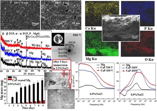
  • With increasing of the MAO voltage from 350 to 500 V the intensity of micro-arc discharges increases, so the thickness and surface roughness (Ra) of CaP coatings on Mg alloy increase linearly from 6 to 150 µm and from 2.0 to 8.0 µm, respectively.
  • The maximal Ca and P concentrations and, as consequently, maximal Ca/P ratio are detected in the surface regions with accumulation of isometric β-TCP particles for the coatings deposited at 350 V. With increase in the voltage to 500 V, the Ca/P ratio in these regions decreases from 1.7 to 1.0 and the Ca/P ratio in the coating surface area without β-TCP particles increases from 0.7 to 0.9. It is associated with partial dissolution and transformation of β-TCP particles in the powerful high temperature micro-arc discharges fields under the high voltages.
  • The coatings deposited at 350 V have homogeneous porous morphology and structure with micro-pores close in size (1.5–3.0 µm). The formation of large pores occurred at higher voltages of 450–500 V at the expense of the smaller ones.
  • The β-Ca3(PO4)2, α-Ca3(PO4)2 and MgO crystalline phases are formed in the coatings deposited at the MAO voltages of 350–400 V. β-TCP is partially transformed into a high-temperature α-TCP phase during the MAO process. The increase of the voltage to 450–500 V leads to the partial dissolution of α-TCP with formation of HA phase in the coatings.
  • The biodegradation rate of the CaP coated Mg alloy is almost 10 times less than uncoated alloy.
  • The potentiodynamic polarization data have shown the reduction of the corrosion current of CaP coated Mg alloy in comparison to the uncoated alloy. This reduction for the coatings deposited at 350 and 450 V was 2 and 10 times, correspondingly. This is due to the change of the phase composition and the growth of the coating thickness.
  • The levels of barrier properties of the studied samples estimated by the electrochemical measurements are directly related to the thicknesses and the phase composition of the deposited layers, the thicker coatings containing hydroxyapatite provide the higher protection.

Acknowledgments

The work was supported by a Program of Fundamental Researches of Siberian Branch of Russian Academies of Sciences (Project No.III.23.2.5). The authors are grateful to A.I. Tolmachev and P.V. Uvarkin from the Institute of Strength Physics and Materials Science SB RAS (Tomsk, Russia) for their assistance in preparation of the experimental materials and XRD analysis, respectively.

Author Contributions

Mariya B. Sedelnikova, Ekaterina G. Komarova and Yurii P. Sharkeev have performed the experimental study, analysis of the SEM, TEM, XRD and EDX data, and writing the paper; Tatiana V. Tolkacheva and Aigerim A. Kazakbaeva have contributed towards the reagents and materials tools; Vladimir V. Sheikin has performed the corrosion tests; Vladimir S. Egorkin and Dmitry V. Mashtalyar have performed the electrochemical study, Juergen Schmidt has developed the magnesium alloy.

Conflicts of Interest

The authors declare no conflict of interest.

References

  1. Tian, P.; Liu, X. Surface modification of biodegradable magnesium and its alloys for biomedical applications. Regener. Biomater. 2015, 2, 135–151. [Google Scholar] [CrossRef] [PubMed]
  2. Zhang, T.; Wu, X.; Huang, H.; Zhang, Y.; Li, M.; Lan, G.; Xia, H.; Yin, Q. The beneficial influence of microarc oxidation-coated magnesium alloy on the adhesion, proliferation and osteogenic differentiation of bone marrow stromal cells. Mater. Lett. 2014, 137, 362–365. [Google Scholar] [CrossRef]
  3. Sillekens, W.H. Magnesium-based biodegradable implants. Emerg. Mater. Res. 2013, 2, 216–218. [Google Scholar] [CrossRef]
  4. Witte, F.; Hort, N.; Vogt, C.; Cohen, S.; Kainer, K.U.; Willumeit, R.; Feyerabend, F. Degradable biomaterials based on magnesium corrosion. Curr. Opin. Solid State Mater. Sci. 2008, 12, 63–72. [Google Scholar] [CrossRef]
  5. Fischer, J.; Pröfrock, D.; Hort, N.; Willumeit, R.; Feyerabend, F. Reprint of: Improved cytotoxicity testing of magnesium materials. Mater. Sci. Eng 2013, 176, 1773–1777. [Google Scholar] [CrossRef]
  6. Zhang, C.Y.; Seng, R.C.; Liu, C.L.; Gao, J.C. Comparison of calcium phosphate coatings on Mg-Al and Mg-Ca alloys and their corrosion behavior in Hank’s solution. Surf. Coat. Technol. 2010, 201, 3636–3640. [Google Scholar] [CrossRef]
  7. Lin, X.; Wang, X.; Tan, L.; Wan, P.; Yu, X.; Li, Q.; Yang, K. Effect of preparation parameters on the properties of hydroxyapatite containing micro-arc oxidation coating on biodegradable ZK60 magnesium alloy. Ceram. Int. 2014, 40, 10043–10051. [Google Scholar] [CrossRef]
  8. Wu, H.; Zhang, R.; Li, X.; Ni, J.; Zhao, C.; Song, Y.; Wang, J.; Zhang, S.; Zheng, Y.; Zhang, X. Doping inorganic ions to regulate bioactivity of Ca-P coating on bioabsorbable high purity magnesium. Prog. Nat. Sci. Mater. Int. 2014, 24, 479–485. [Google Scholar] [CrossRef]
  9. Staiger, M.P.; Pietak, A.M.; Huadmai, J.; Dias, G. Magnesium and its alloys as orthopedic biomaterials: A review. Biomaterials 2006, 27, 1728–1734. [Google Scholar] [CrossRef] [PubMed]
  10. Shadanbaz, S.; Dias, G.J. Calcium phosphate coatings on magnesium alloys for biomedical applications: A review. Acta Biomater. 2012, 8, 20–30. [Google Scholar] [CrossRef] [PubMed]
  11. Pan, Y.K.; Chen, C.Z.; Wang, D.G.; Lin, Z.Q. Preparation and bioactivity of micro-arc oxidized calcium phosphate coatings. Mater. Chem. Phys. 2013, 141, 842–849. [Google Scholar] [CrossRef]
  12. Hermawan, H.; Dubé, D.; Mantovani, D. Developments in metallic biodegradable stents. Acta Biomater. 2010, 6, 1693–1697. [Google Scholar] [CrossRef] [PubMed]
  13. Erbel, R.; Mario, C.D.; Bartunek, J.; Bonnier, J.; Bruyne, B.; Eberli, F.R.; Erne, P.P.; Haude, P.M.; Heublein, B.; Horrigan, M.; et al. Temporary scaffolding of coronary arteries with bioabsorbable magnesium stents: A prospective, non-randomised multicentre trial. Lancet 2007, 369, 1869–1875. [Google Scholar] [CrossRef]
  14. Gu, X.N.; Zheng, Y.F. A review on magnesium alloys as biodegradable materials. Front. Mater. Sci. China 2010, 4, 111–115. [Google Scholar] [CrossRef]
  15. Abdal-hay, A.; Dewidar, M.; Lim, J.K. Biocorrosion behavior and cell viability of adhesive polymer coated magnesium based alloys for medical implants. Appl. Surf. Sci. 2012, 261, 536–546. [Google Scholar] [CrossRef]
  16. Zong, Y.; Yuan, G.; Zhang, X.; Mao, L.; Niu, J.; Ding, W. Comparison of biodegradable behaviors of AZ31 and Mg-Nd-Zn-Zr alloys in Hank’s physiological solution. Mater. Sci. Eng. B 2012, 177, 395–401. [Google Scholar] [CrossRef]
  17. Narayanan, T.S.N.S.; Park, I.S.; Lee, M.H. Strategies to improve the corrosion resistance of microarc oxidation (MAO) coated magnesium alloys for degradable implants: Prospects and challenges. Prog. Mater. Sci. 2014, 60, 1–71. [Google Scholar] [CrossRef]
  18. Zhang, C.Y.; Zeng, R.C.; Chen, R.S.; Liu, C.L.; Gao, J.C. Preparation of calcium phosphate coatings on Mg-1.0Ca alloy. Trans. Nonferr. Met. Soc. China 2010, 20, 655–659. [Google Scholar] [CrossRef]
  19. Salahshoor, M.; Guo, Y. Biodegradable orthopedic magnesium-calcium (MgCa) alloys, process, and corrosion performance. Materials 2012, 5, 135–155. [Google Scholar] [CrossRef] [PubMed]
  20. Velikokhatnyi, O.I.; Kumta, P.N. First-principles studies on alloying and simplified thermodynamic aqueous chemical stability of calcium-, zinc-, aluminum-, yttrium- and iron-doped magnesium alloys. Acta Biomater. 2010, 6, 1698–1704. [Google Scholar] [CrossRef] [PubMed]
  21. Yao, Z.; Li, L.; Jiang, Z. Adjustment of the ratio of Ca/P in the ceramic coating on Mg alloy by plasma electrolytic oxidation. Appl. Surf. Sci. 2009, 255, 6724–6728. [Google Scholar] [CrossRef]
  22. Chu, C.L.; Han, X.; Bai, J.; Xue, F.; Chu, P.K. Surface modification of biomedical magnesium alloy wires by micro-arc oxidation. Trans. Nonferr. Met. Soc. China 2014, 24, 1058–1064. [Google Scholar] [CrossRef]
  23. Johnston, S.; Shi, Z.; Dargusch, M.S.; Atrens, A. Influence of surface condition on the corrosion of ultra-high-purity Mg alloy wire. Corros. Sci. 2016, 108, 66–75. [Google Scholar] [CrossRef]
  24. Liu, G.Y.; Hu, J.; Ding, Z.K.; Wang, C. Formation mechanism of calcium phosphate coating on micro-arc oxidized magnesium. Mater. Chem. Phys. 2011, 130, 1118–1124. [Google Scholar] [CrossRef]
  25. Li, L.; Zhang, M.; Li, Y.; Zhao, J.; Qin, L.; Lai, Y. Corrosion and biocompatibility improvement of magnesium-based alloys as bone implant materials: A review. Regener. Biomater. 2017, 4, 129–137. [Google Scholar] [CrossRef]
  26. Liu, G.Y.; Tang, S.; Li, D.; Hu, J. Self-adjustment of calcium phosphate coating on micro-arc oxidized magnesium and its influence on the corrosion behaviour in simulated body fluids. Corros. Sci. 2014, 79, 206–214. [Google Scholar] [CrossRef]
  27. Liu, G.Y.; Hu, J.; Ding, Z.K.; Wang, C. Bioactive calcium phosphate coating formed on micro-arc oxidized magnesium by chemical deposition. Appl. Surf. Sci. 2011, 257, 2051–2057. [Google Scholar] [CrossRef]
  28. Zhang, L.; Zhang, J.; Chen, C.F.; Gu, Y. Advances in microarc oxidation coated AZ31 Mg alloys for biomedical applications. Corros. Sci. 2015, 91, 7–28. [Google Scholar] [CrossRef]
  29. Yu, H.; Dong, Q.; Dou, J.; Pan, Y.; Chen, C. Structure and in vitro bioactivity of ceramic coatings on magnesium alloys by microarc oxidation. Appl. Surf. Sci. 2016, 388, 114–119. [Google Scholar] [CrossRef]
  30. Zhang, F.; Cai, S.; Xu, G.; Shen, S.; Li, Y.; Zhang, M.; Wu, X. Corrosion behavior of mesoporous bioglass-ceramic coated magnesium alloy under applied forces. J. Mech. Behav. Biomed. Mater. 2016, 56, 146–155. [Google Scholar] [CrossRef] [PubMed]
  31. Rosemann, P.; Schmidt, J.; Heyn, A. Short and long term degradation behaviour of Mg–1Ca magnesium alloys and protective coatings based on plasma-chemical oxidation and biodegradable polymercoating in synthetic body fluid. Mater. Corros. 2013, 64, 714–722. [Google Scholar] [CrossRef]
  32. Legostaeva, E.V.; Kulyashova, K.S.; Komarova, E.G.; Epple, M.; Sharkeev, Y.P.; Khlusov, I.A. Physical, chemical and biological properties of micro-arc deposited calcium phosphate coatings on titanium and zirconium-niobium alloy. Mat.-Wiss. Werkstofftech. 2013, 44, 188–197. [Google Scholar] [CrossRef]
  33. Sedelnikova, M.B.; Sharkeev, Y.P.; Komarova, E.G.; Khlusov, I.A.; Chebodaeva, V.V. Structure and properties of the wollastonite–calcium phosphate coatings deposited on titanium and titanium–niobium alloy by the micro-arc oxidation method. Surf. Coat. Technol. 2016, 307, 1274–1283. [Google Scholar] [CrossRef]
  34. Sharkeev, Y.; Komarova, E.; Sedelnikova, M.; Sun, Z.M.; Zhu, Q.F.; Zhang, J.; Tolkacheva, T.; Uvarkin, P. Structure and properties of micro-arc calcium phosphate coatings on pure titanium and Ti-40Nb alloy. Trans. Nonferr. Met. Soc. China 2017, 27, 125–133. [Google Scholar] [CrossRef]
  35. Dzhurinskiy, D.; Gao, Y.; Yeung, W.K.; Strumban, E.; Leshchinsky, V.; Chu, P.J.; Matthews, A.; Yerokhin, A.; Maev, R.G. Characterization and corrosion evaluation of TiO2: N-HA coatings on titanium alloy formed by plasma electrolytic oxidation. Surf. Coat. Technol. 2015, 269, 258–265. [Google Scholar] [CrossRef]
  36. Kazek-Kęsik, A.; Krok-Borkowicz, M.; Pamuła, E.; Simka, W. Electrochemical and biological characterization of coatings formed on Ti–15Mo alloy by plasma electrolytic oxidation. Mater. Sci. Eng. C 2014, 43, 172–181. [Google Scholar] [CrossRef] [PubMed]
  37. Kazek-Kęsik, A.; Dercz, G.; Suchanek, K.; Kalemba–Rec, I.; Piotrovski, J.; Simka, W. Biofunctionalization of Ti–13Nb–13Zr alloy surface by plasma electrolytic oxidation. Part I. Surf. Coat. Technol. 2015, 276, 59–69. [Google Scholar] [CrossRef]
  38. Santos, C.; Piedade, C.; Uggowitzer, P.J.; Montemor, M.F.; Carmezim, M.J. Parallel nano-assembling of a multifunctional GO/HapNP coating on ultrahigh-purity magnesium for biodegradable implants. Appl. Surf. Sci. 2015, 345, 387–393. [Google Scholar] [CrossRef]
  39. Sreekanth, D.; Rameshbabu, N. Development and characterization of MgO/hydroxyapatite composite coating on AZ31 magnesium alloy by plasma electrolytic oxidation coupled with electrophoretic deposition. Mater. Lett. 2012, 68, 439–442. [Google Scholar] [CrossRef]
  40. Elsayed, F.R.; Hort, N.; Salgado-Ordorica, M.A.; Kainer, K.U. Magnesium permanent mold castings optimization. Mater. Sci. Forum 2011, 690, 65–68. [Google Scholar] [CrossRef]
  41. ASTM International. ASTM G59–97. Standard Test Method for Conducting Potentiodynamic Polarization Resistance Measurements; ASTM International: West Conshohocken, PA, USA, 2009. [Google Scholar]
  42. Shi, Z.; Liu, M.; Atrens, A. Measurement of the corrosion rate of magnesium alloys using Tafel extrapolation. Corros. Sci. 2010, 52, 579–588. [Google Scholar] [CrossRef]
  43. Shi, Z.; Atrens, A. An innovative specimen configuration for the study of Mg corrosion. Corros. Sci. 2011, 53, 226–246. [Google Scholar] [CrossRef]
  44. Cao, F.; Shi, Z.; Hofstetter, J.; Uggowitzed, P.J.; Song, G.; Liu, M.; Atrens, A. Corrosion of ultra-high-purity Mg in 3.5% NaCl solution saturated with Mg(OH)2. Corros. Sci. 2013, 75, 78–99. [Google Scholar] [CrossRef]
  45. Gu, Y.; Xiong, W.; Ning, C.; Zhang, J. Residual stresses in microarc oxidation ceramic coatings on biocompatible AZ31 magnesium alloys. J. Mater. Eng. Perform. 2012, 21, 1085–1090. [Google Scholar] [CrossRef]
  46. Song, Y.W.; Shan, D.Y.; Han, E.H. Electrodeposition of hydroxyapatite coating on AZ91D magnesium alloy for biomaterial application. Mater. Lett. 2008, 62, 3276–3279. [Google Scholar] [CrossRef]
  47. Dorozhkin, S.V. Calcium orthophosphates (CaPO4): Occurrence and properties. Prog. Biomater. 2016, 5, 9–70. [Google Scholar] [CrossRef] [PubMed]
  48. Gnedenkov, S.V.; Khrisanfova, O.A.; Zavidnaya, A.G.; Sinebryukhov, S.L.; Egorkin, V.S.; Nistratova, M.V.; Yerokhin, A.; Matthews, A. PEO coatings obtained on an Mg-Mn type alloy under unipolar and bipolar modes in silicate-containing electrolytes. Surf. Coat. Technol. 2010, 204, 2316–2322. [Google Scholar] [CrossRef]
Figure 1. Photos of the system for evaluation of hydrogen liberation.
Metals 08 00238 g001
Figure 2. Current density with time of the micro-arc oxidation (MAO) process for deposition of CaP coatings on Mg alloy under different voltages.
Metals 08 00238 g002
Figure 3. The thickness (a) and roughness Ra (b) of the CaP coatings against the MAO voltage.
Metals 08 00238 g003
Figure 4. Scanning electron microscopy (SEM) micrographs of the cross-sectional CaP coatings deposited under different MAO voltages, V: (a) −350; (b) −450; (c) −500.
Metals 08 00238 g004
Figure 5. SEM micrographs of the surface of the CaP coatings deposited under different voltages (ac) and of the β-tricalcium phosphate (β-TCP) particles (d).
Metals 08 00238 g005
Figure 6. The histograms of the pore distribution by sizes for CaP coatings deposited under different MAO voltages, V: (a) −350; (b) −450; (c) −500.
Metals 08 00238 g006
Figure 7. SEM micrographs of the top surface (a) and cross-sectional CaP coatings (b,c) deposited at 450 V for 5 min and energy-dispersive X-ray spectroscopy (EDX) mapping of the elemental distribution within the coatings (dh).
Metals 08 00238 g007
Figure 8. XRD patterns of the CaP coatings deposited on Mg-0.8Ca under different voltages for 5 min. β–β-Ca3(PO4)2, α–α-Ca3(PO4)2, HA–Ca10(PO4)6(OH)2, P–MgO (periclase), Mg—magnesium.
Metals 08 00238 g008
Figure 9. Transmission electron microscopy (TEM) bright field (BF) images and selected area diffraction (SAD) patterns of the fragments of the CaP coatings deposited for 5 min under different MAO voltages (V): (a) −400; (b) −500; α-TCP–α; β-TCP–β.
Metals 08 00238 g009
Figure 10. Volume of evolved hydrogen (a) and the mass of released magnesium into 0.9% NaCl solution (b) with time.
Metals 08 00238 g010
Figure 11. Potentiodynamic polarization curves obtained in 0.9% NaCl for: 1—bare Mg alloy; 2—CaP coated Mg (350 V, 10 min); 3—CaP coated Mg (450 V, 10 min).
Metals 08 00238 g011
Figure 12. Impedance modulus vs. frequency dependencies (a) and phase angle theta vs. frequency dependencies (b) obtained in 0.9% NaCl for: 1—bare Mg alloy; 2—CaP coated Mg (350 V, 10 min); 3—CaP coated Mg (450 V, 10 min).
Metals 08 00238 g012
Table 1. Electrochemical parameters of the samples.
SampleEC, V (Ag/AgCl)jC, A cm−2Rp, Ω cm2|Z|f→0 Hz, Ω cm2
1−1.357.0 × 10−64.3 × 1032.0 × 102
2−1.581.8 × 10−62.0 × 1041.5 × 104
3−1.657.2 × 10−74.6 × 1046.1 × 104

