Article

Research on the Bonding Interface of High Speed Steel/Ductile Cast Iron Composite Roll Manufactured by an Improved Electroslag Cladding Method

1
School of Metallurgy, Northeastern University, Shenyang 110819, China
2
School of Materials and Metallurgy, University of Science and Technology Liaoning, Anshan 114051, China
3
E.O. Paton Welding Institute of Ukraine, 03150 Kyiv, Ukraine
4
Elmet-Roll, 03150 Kyiv, Ukraine
*
Authors to whom correspondence should be addressed.
Metals 2018, 8(6), 390; https://doi.org/10.3390/met8060390
Submission received: 17 April 2018 / Revised: 25 May 2018 / Accepted: 25 May 2018 / Published: 28 May 2018
(This article belongs to the Special Issue Ironmaking and Steelmaking)

Abstract

:
In the present study, a new electroslag cladding method by using of the advanced current supplying mold technology was used for manufacturing the high speed steel (HSS)/ductile cast iron (DCI) composite roll. The graphite morphology, matrix microstructure, elements distribution, carbides morphology, and carbides composition have been investigated by means of optical microscope (OM), scanning electron microscope (SEM), and energy dispersive spectroscopy (EDS). With increasing distance from the HSS side, a transition of graphite morphology from naught to existence and from small and dispersed to large and nonuniform was obtained at the interface. It was closely related to the fact that graphite in DCI participated in the phase change and the roll core surface and its nearby positions was heated to a high temperature by the liquid slag during the whole electroslag cladding process. Due to the combined effects of melting and elements diffusion, a significant migration of the alloying elements have occurred through the line scan analysis. Based on this, different types of carbides with the morphology and composition were found at the bonding interface. In addition, no obvious slag inclusions, porosity, shrinkage and other defects at the bonding interface were found. Results of the tensile test also illustrated that the bonding interface had a good quality and it could fully meet the requirements of the roll.

1. Introduction

In the field of hot rolling plants, rolling conditions have gradually become complicated due to the increasing demands for not only high quality of sheet product shape and sheet surface condition but also high productivity and energy saving in rolling. High speed steel (HSS) rolls are generally characterized of much higher hardness and more excellent resistance to wear, oxidization and roughness by adding strong carbide forming elements like V, W, Mo, and Cr to form very hard carbides of MC, M2C, and M7C3 than the conventional work rolls such as indefinite chilled roll, Ni-grain cast iron roll and high chromium cast iron roll. In addition, the high speed steel also has a good capacity to retain a high level of hardness at high temperatures. It is widely used to manufacture hot rolling rolls to produce strips of good shape and small crown with extended roll service life [1,2,3].
Ductile cast irons are a family of alloys consisting of graphite spheroids dispersed in a matrix similar to that of steel, which combine the principle advantages of gray iron (low melting point, good fluidity and castability, excellent machinability, and good wear resistance) with the engineering advantages of steel (high strength, toughness, ductility, hot workability, and hardenability).
To date, centrifugal casting method has been widely used for manufacturing the composite roll especially in the production field of high speed steel (HSS)/ductile cast iron (DCI) composite roll [4,5,6]. However, it has some inevitable weakness points as described below. Firstly, as the high speed steel contains many carbide forming elements like V, W, Mo and Cr, the density (g/cm3) difference between V (5.8), W (19.1), Mo (10.2), and Fe (7.86) is very large, it is not suitable to be manufactured by the conventional centrifugal casting method because of the composition segregation and the nonuniformity of microstructure and mechanical properties in the roll outer shell [1]. Secondly, when the liquidus temperature of the roll core material is higher than that of the composite layer, the final poured liquid metal of the roll core is fused with the inner surface of the solidified composite layer. This molten layer has a lower liquidus temperature than that of the roll core and becomes the final site of the solidification, which can easily lead to casting defects and reduce the strength of the bonding interface [7]. Thirdly, the centrifugal casting method can’t use forged steel as the roll core material, which limits its application in the production field of high strength and toughness composite roll. In comparison with the centrifugal casting method, the improved electroslag cladding method [8] does not have the above problems, it not only can improve the purity of the molten steel but also can effectively improve the composition segregation during the solidification process of composite layer molten steel. However, it is worth mentioning that the improved electroslag cladding method has a larger production cost and more complex operation control. Based on the comprehensive consideration of the advantages and disadvantages of this two methods, the improved electroslag cladding method is a good choice for the production of high quality composite roll.
Performance of the composite roll is closely related to its bonding interface properties which can be said to be the key to the success of producing composite roll. However, the bonding interface is always the weakest region of a composite roll [9] as the composite layer easily cracks and flakes when the metallurgical bonding is incomplete, so, it is necessary to check carefully and improve the performance at the bonding interface effectively. This study attempts to reveal the bonding characteristic the bimetallic interface between HSS and DCI of the composite roll.

2. Experimental

In the present study, an improved electroslag cladding method with the electrode—current supplying mold conductive circuit [8] was used to manufacture the HSS/DCI composite roll. Schematic diagram of the new improved electroslag cladding method is shown in Figure 1. It mainly includes a T-type mold, consumable electrodes, slag bath, composite layer, roll core, current supplying mold and a pair of metal level sensors. The upper part of the T-type mold is a Φ420 mm current supplying mold, while solidification of the molten steel used as the composite layer occurs in the lower Φ350 mm water-cooled mold.
According to the numerical simulation results [8], by adoption of the current supplying mold in the improved electroslag cladding process, the highest temperature value occurs in the slag pool that between the consumable electrode and mold which is far away from the roll core surface, it reduces the heat transfer from slag pool to roll core effectively which results in an flexible control of the roll core surface temperature. It is worth mentioning that the melting temperature difference between the two materials is very important for the operation and technological parameter match during the bimetallic composite process.
For the experimental research, the ductile cast iron is used as the roll core with a diameter of Φ240 mm and the high speed steel is used as the composite layer material. Twenty consumable electrodes of AISI M2 HSS with the size of Φ30 × 1500 mm were welded evenly on a disc and then they were inserted in the space between roll core and the molds. The chemical composition of the DCI and M2 HSS are given in Table 1.
In the present study, a HSS/DCI composite roll with the diameter of 350 mm and composite height of 264 mm was produced by the above method and it was mainly used to investigate the bonding characteristics of the bimetallic interface between HSS and DCI during the electroslag cladding process. It was cut after a stress relief annealing heat treatment at 1023 K for 6 h. Figure 2 shows the sampling schematic of roll core, composite layer and bimetallic bonding interface as described below.
Metallographic samples of roll core before and after the electroslag cladding process were taken from the position marked by the letters “R1/R2” in Figure 2, respectively, to analyze its influence on the DCI microstructure. A sample of composite layer was taken from the position marked by the letter “C1” and it was used to observe the HSS microstructure. In order to research the graphite morphology and microstructure of the bimetallic bonding interface, a sample was taken from the position marked by the letter “B1” in Figure 2. It was polished and then etched with 4% nitric acid alcohol to observe the carbides morphology and measure the carbides composition as well as the matrix by using the UltraPlus scanning electron microscope (SEM, Carl Zeiss AG, Oberkochen, Germany) and energy dispersive spectroscopy (EDS, Carl Zeiss AG, Oberkochen, Germany). At last, a tensile test and hardness test were carried out to evaluate the mechanical properties of the bimetallic bonding interface. The tensile specimen was taken from the bimetallic interface and it was a plane plate specimen with the thickness of 4 mm and the total length of 108 mm. The tensile tests process were carried out by the AG-Xplus100kN electronic universal testing machine (Shimadzu, Tokyo, Japan) with the strain rate of 0.278 s−1 in the present study. During the hardness test process, an HRS-150D digital Rockwell hardness tester (Shanghai JvJing Precision Instrument manufacturing Co., Ltd., Shanghai, China) was used and the testing load was 1471 N. The measuring distance between two adjacent points in the radial direction was 5 mm, the hardness value of a point was obtained after averaging three measurements.

3. Results and Discussion

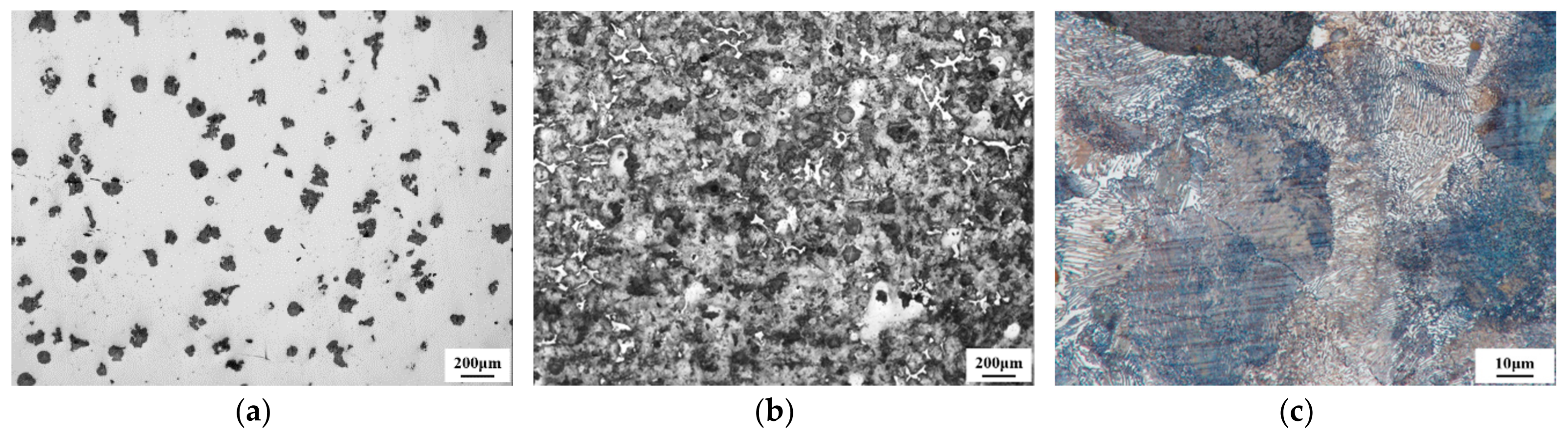
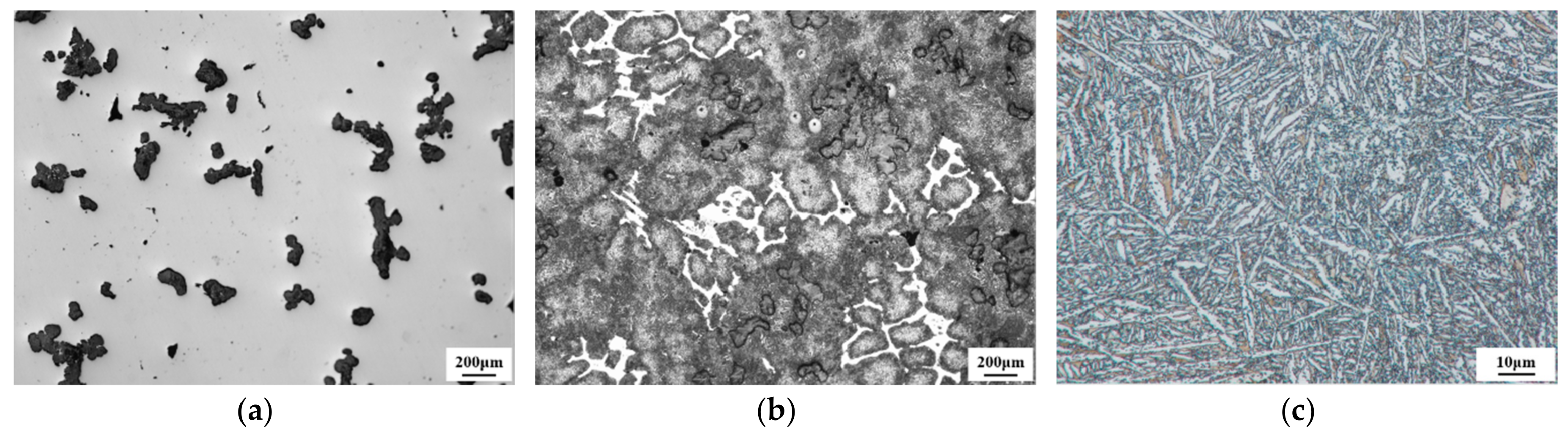
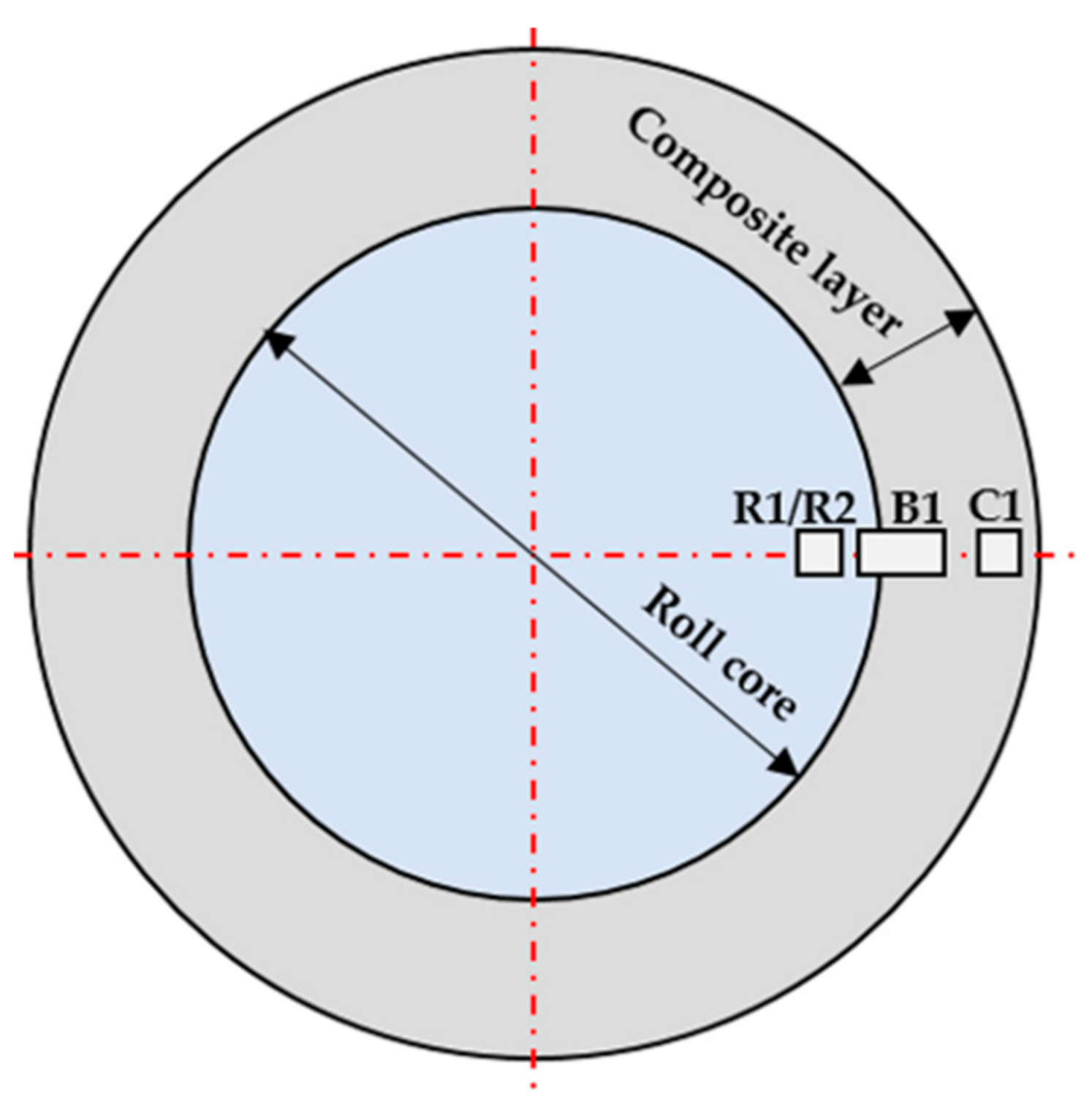
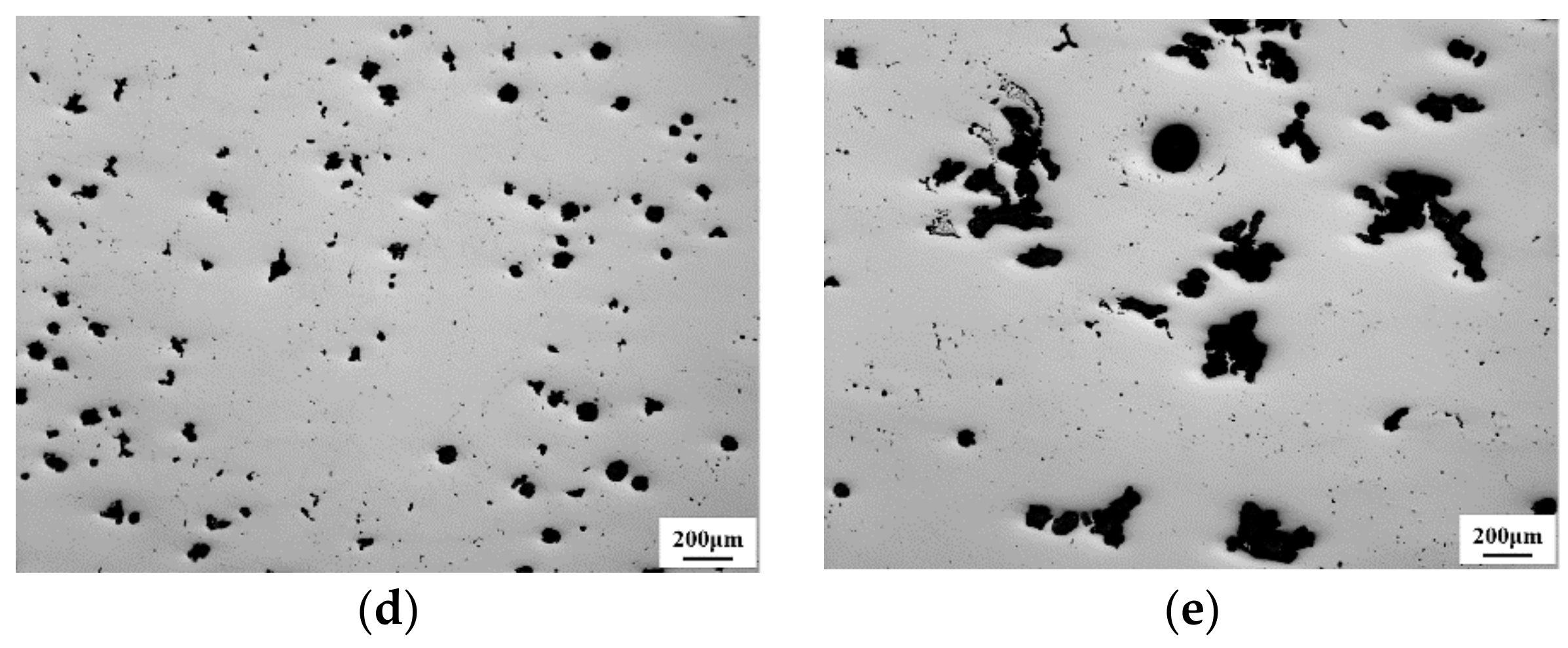
3.1. Graphite Morphology and Microstructure of Roll Core before and after the Cladding Process

The mechanical properties of ductile cast iron are seriously influenced by the morphology of the graphite nodule, including count, diameter, sphericity, and spatial distribution. For instance, the sphericity and spatial distribution of nodules affect strength and toughness. Fatigue strength is influenced by count and diameter [10,11].
Graphite spheroidization rate is a representation of the degree for the graphite morphology nearly spherical and the graphite rating is based on the percentage of graphite spheroidization rate. Figure 3 shows the graphite morphology and microstructure of DCI before the cladding process. Figure 3a illustrates that the graphite morphology is basically spheroidal and agglomerated (isolated distribution, irregular shape) without chunky graphite. The graphite rating is second grade through a comparison with the graphite rating maps. For the cast iron roll, requirement of the graphite rating is not less than third grade. So, it can well meet the requirements of the cast iron roll. As Ni element can stabilize austenite and promote the formation of pearlite, a small amount of Ni element can inhibit the ferrite formation. Therefore, before the cladding process, the matrix of the DCI is a pearlitic matrix as shown in Figure 3c. In addition, iron atoms in Fe3C can be replaced by other metal atoms to form solid solutions which are generally referred to as “alloy cementite” in the present study. During this process, the Cr element is finitely soluble in Fe3C, while the W and Mo elements are only slightly soluble in Fe3C, V is almost insoluble in Fe3C. As the DCI contains some carbide forming elements like Cr and Mo, some alloy cementite has been generated during its solidification process as shown in Figure 3b.
Figure 4 shows the graphite morphology and microstructure of DCI after the cladding process of bimetallic metals. Compared with that in Figure 3, the graphite spheroidization rate, number of graphite particles per unit area and area percentage of the graphite after the cladding process are changed from second grade, 21.56/mm2 and 8.37% to third grade, 8.79/mm2 and 11.41%, respectively. Through the comparison, a less sphericity, smaller count and larger diameter of the graphite are obtained after the cladding process. During the electroslag cladding process, the roll core of DCI was preheated continuously by the heat conduction from the high temperature liquid slag bath, and then it participated in the cladding process with the molten electrodes metal which used to form the composite layer. In the present study, the roll core surface and its nearby positions have been heated to a very high temperature during the whole cladding process. As the austenitizing temperature of DCI is only 1080 K through the calculation of thermo-calc software, a high temperature austenitizing process have been performed in the heat affected zone (the position near the roll core surface) of roll core during the electroslag cladding process. When the heated temperature of DCI exceeds the austenitizing temperature by a certain value, the graphite can be disintegrated with different degrees and it will be described in detail below. The disintegration methods include peripheral exfoliation type, center melting type, and cracking type. Different disintegration methods will lead to different graphite morphology [12]. The disintegrated graphite is shown in Figure 4a.
Due to the preheating process and the subsequent bimetallic cladding and cooling process of the roll core, the content of alloy cementite has an obvious increase and it always precipitates in network between eutectic cells as shown in Figure 4b. The matrix microstructure of the DCI after the cladding process mainly consists of needle-like bainite and partial granular bainite as shown in Figure 4c. During the high temperature austenitizing process, the graphite is also involved in the phase change process as a phase in DCI. The presence of graphite is equivalent to a “carbon storage pool” and when the DCI is heated to a certain temperature, the graphite begins to disintegrate and dissolve to some extent which leads to an increase of carbon content in the austenite. Because of the rapid cooling during the electroslag cladding process, the microstructure transformation of austenitized DCI will be based on the Fe-Fe3C metastable equilibrium phase diagram. As this time, graphite is no longer precipitated from the supersaturated austenite but secondary cementite. This secondary cementite precipitated from the austenite is usually distributed in network along the austenite grain boundary. The presence of network cementite will greatly reduce the mechanical properties of the DCI, especially the plasticity and toughness.

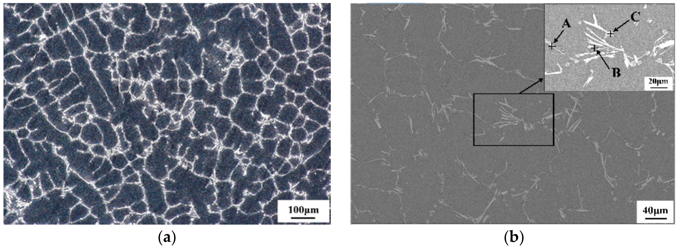
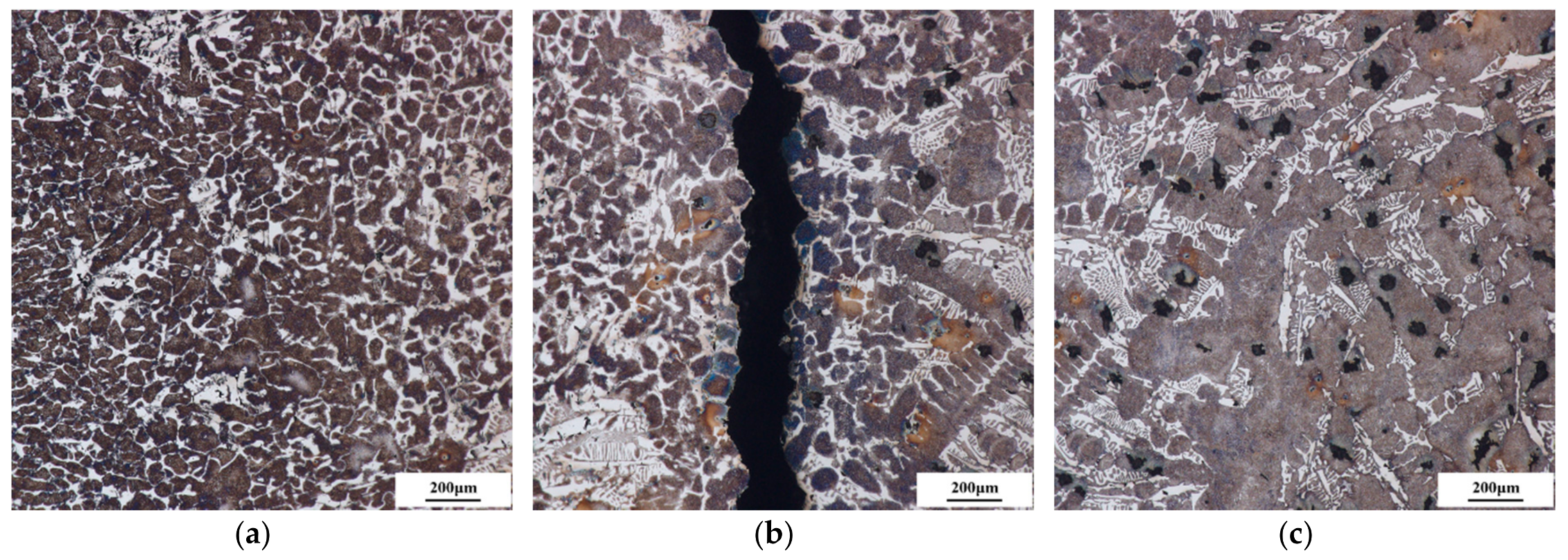
3.2. Microstructure of the Composite Layer

Microstructure of the composite layer (HSS) etched with 4% nitric acid alcohol are shown in Figure 5 and the chemical composition of the carbides as indicated by arrows in Figure 5b are shown in Table 2. It shows that the eutectic carbides are mostly located in the intercellular regions, forming continuous networks of densely populated carbides. Through the carbides composition, two types of carbides such as spherical or blocky MC carbides (point C) and plate-like M2C carbides (point A and B) are found in these micrographs. As the low content of V element in the steel, MC carbides are concentrated on cell boundaries rather than inside cells. MC carbides are rich in V and W whereas plate-like M2C carbides are rich in W and Mo but poor in Fe as shown in Table 2. It is known that M2C carbides are created by the eutectic reaction, L → γ + M2C [13]. In austenite-carbide eutectics, carbide with higher fusion entropy is generally considered to be a faceted phase, which grows anisotropically during solidification. The morphology and microstructure of plate-like M2C exhibit representative characteristics of a faceted phase [14]. From the Figure 5, it can be seen that the M2 HSS ingots consist of numerous M2C carbides with a small amount of MC carbides which is consistent with the report by Zhou et al. [14] through the X-ray diffraction analysis.

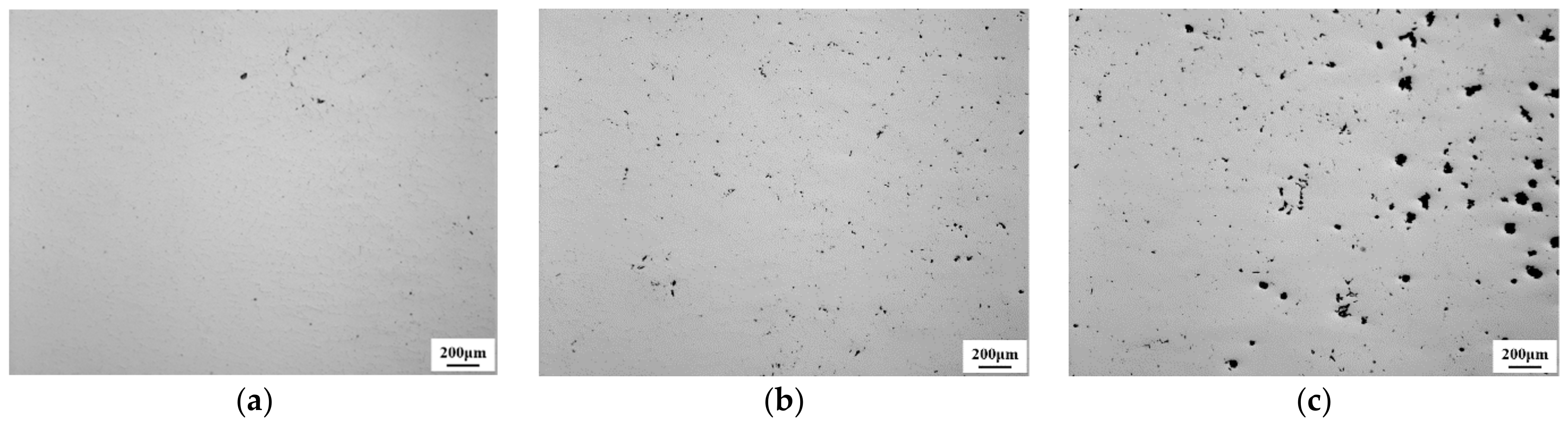
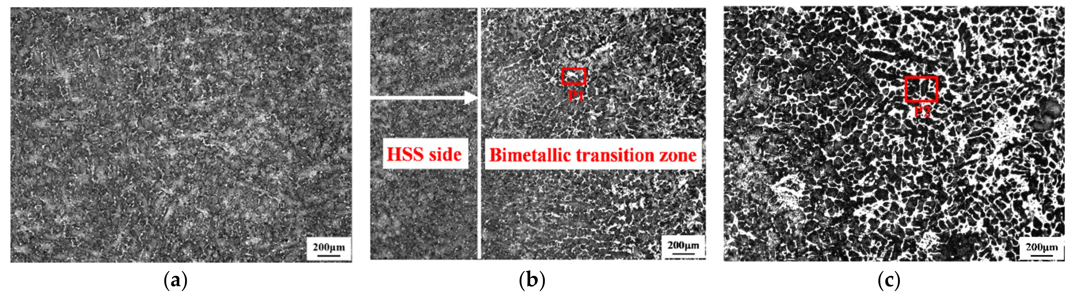
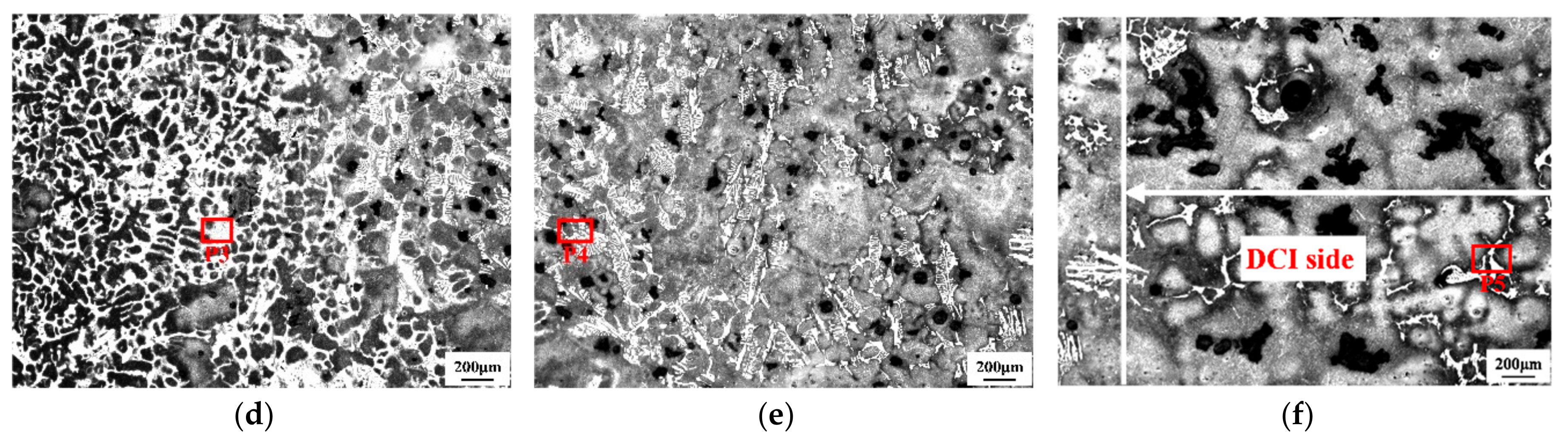
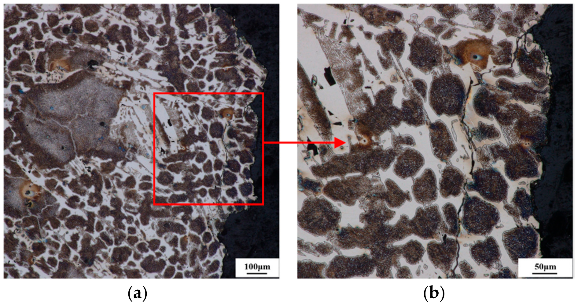
3.3. Graphite Morphology Analysis in the Bimetallic Bonding Interface

Figure 6 gives a clear display of the graphite morphology changes in the bimetallic bonding interface of the HSS/DCI composite roll through the optical microscope.
Though the Figure 6, it can be seen that there are no defects such as slag inclusion and porosity in the bonding interface and a good metallurgical bonding status is achieved. There also exists an obvious transition layer between HSS and DCI and in where the graphite morphology shows obvious changes. At the DCI side, a nonuniform distribution with a poor sphericity, big size, and flowering morphology of the graphite is obtained as shown in Figure 6e. Near the DCI side, the flowering graphite gradually disappeared and turned into spherical graphite with a relatively good sphericity and uniform distribution as shown in Figure 6d. During the transition from DCI to HSS side, the graphite morphology changes again and transforms into fine and dispersed graphite particles as shown in Figure 6b,c. Near the HSS side, the graphite particles gradually disappears.
During the electroslag cladding process of the bimetallic metals, the roll core (DCI) undergoes a continuous heating process. As a phase of the DCI, the graphite must have some changes during this heating process. For this objective, the morphological changes of spheroidal graphite under the continuous heating were observed by HM-350 high temperature metallographic microscope [11]. It illustrates that the transformation of pearlite into austenite after 1023 K has been very obvious. From about 1173 K, the austenitization of pearlite has been completed. As the temperature continues to rise to 1358 K, the matrix around the graphite particles melts firstly due to the interfacial reaction between austenite and graphite which results in a low melting point liquid phase. Presence of the liquid phase accelerates the dissolution of graphite particles in turn. As the inhomogeneous structure of the graphite, the melting of carbon atoms shows a nonuniform development. With the disintegration of the original spheroidal and agglomerated graphite, the deformity graphite as flowering graphite are gradually formed. As it has been described above, different disintegration methods will lead to different graphite morphology. As the heating temperature of DCI continues to increase, the disintegrated graphite (flowering graphite) dissolves into the matrix much further, with a different amount of dissolution, it gradually forms the morphological changes of graphite as shown in Figure 6a–e.

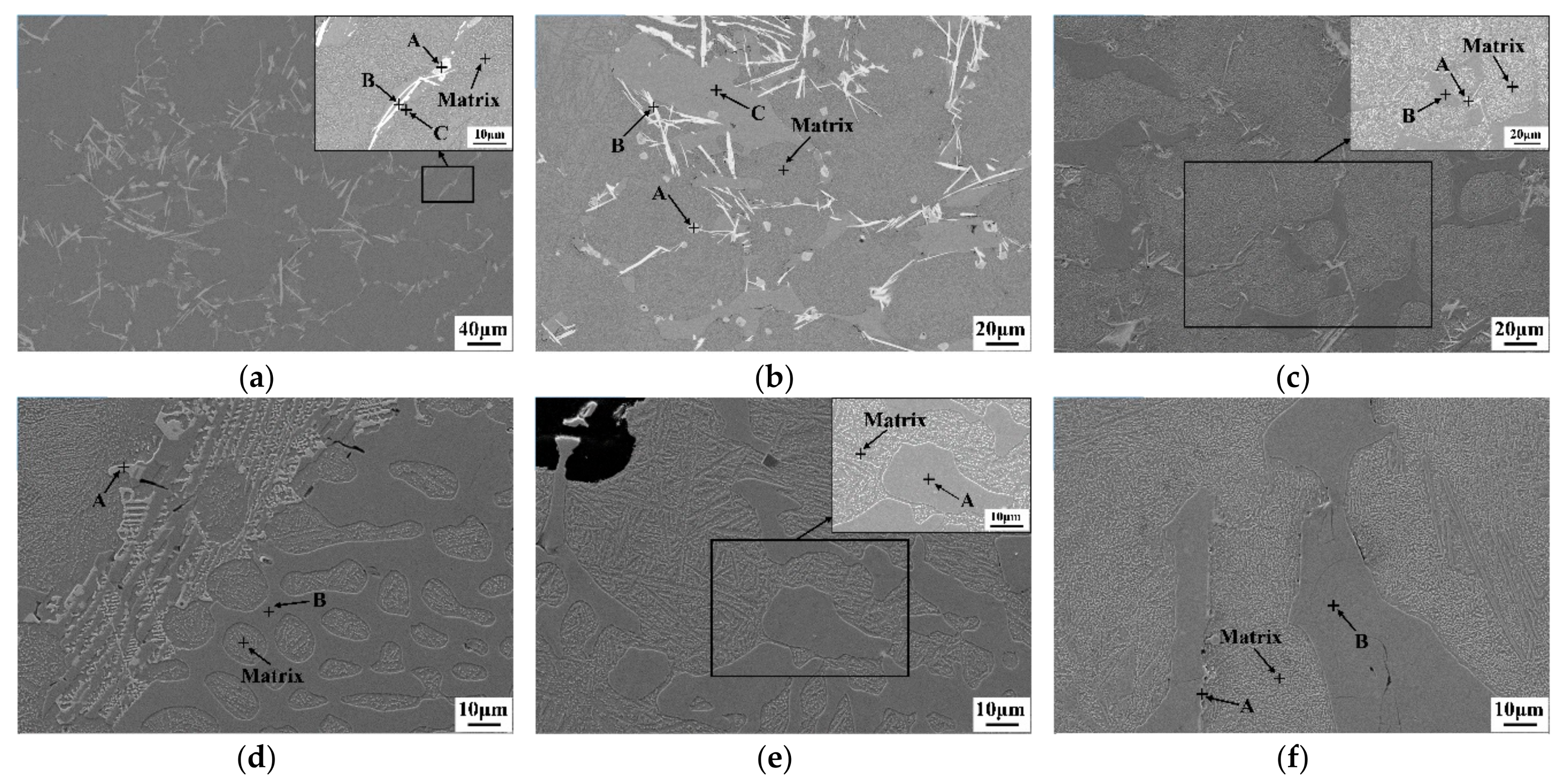
3.4. Microstructure Analysis in the Bimetallic Bonding Interface

As a partial melting phenomenon of the roll core surface has occurred during the electroslag cladding process, the combined effects of the melting and element diffusion occurs in the bimetallic bonding interface. With the combined effects, different microstructures are formed as shown in Figure 7. However, the measurement area moves 3 mm towards the HSS side when compared with that in the Figure 6.
From Figure 7, three areas of the HSS side (Figure 7a), bimetallic transition zone (Figure 7b–e) and DCI side (Figure 7f) are defined according to the different microstructures morphology in the bimetallic bonding interface. Under this definition, width of the bimetallic transition zone is about 11.44 mm and in where four categories of carbides morphology are formed due to the combined effects of the melting and elements diffusion of C, W, Mo, Cr, and V between the HSS side and DCI side. At the HSS side, the fine and dispersed carbides are formed with a uniform distribution. In the bimetallic transition zone, with an increasing distance from the HSS side, the small network carbides gradually become coarse and its content also increases dramatically. In the spheroidal and agglomerated graphite position (Figure 7e), significant transformed ledeburite are formed and the eutectic cementite are very coarse with a nonuniform distribution. Finally, at the DCI side, the small amount and dispersed network carbides are formed which are located in the matrix of the DCI.
In order to give a better understanding of the carbides morphology and composition in the bimetallic bonding interface, the SEM-EDS analyses have been made for the carbides of different positions and the results are shown in Figure 8 and Table 3, respectively. Figure 8a shows the carbides morphology at some area of the HSS side as it is difficult to mark the actual analysis position and Figure 8b–f shows that of the positions marked by the red frames and letters “P1” to “P5” in Figure 7b–f respectively.
At the HSS side (Figure 8a), since the area marked by the letter A mainly contains V and W elements and its small spherical or blocky morphology, it is identified to be the MC carbide. The white-colored area marked by the letter B indicates a plate-like M2C carbide containing mostly W and Mo. The gray-colored area C mainly consists of Fe and Cr as well as few amount of W, Mo, and V, it is identified to be coarse network (or blocky) alloy cementite in where the iron atoms can be replaced by other metal atoms like Cr, W, Mo, and V. It is worth noting that the M2C carbide and MC carbide mainly occurs on the blocky alloy cementite. Compared with Figure 8a, the biggest difference is that the volume fraction of alloy cementite increases obviously as shown in Figure 8b. In Figure 8c, a large amount of coarse blocky alloy cementite are formed, which are distributed in the network shape structure to a certain extent. In this position, no MC carbides are found. Figure 8d shows that the fishbone-like M6C carbide is also found on the blocky alloy cementite and there is a significantly increase of the carbides content and size when compared to that in the Figure 8a–c. Near the DCI side as shown in Figure 8e, it only contains the coarse eutectic cementite in which a certain amount of Cr as well as few W, Mo, and V alloying elements are also found as shown in Table 3. At the DCI side, a very small amount of phase precipitation was found at the edge of the cementite as shown in Figure 8f.
Composition of the carbides and matrix in different positions of bimetallic bonding interface corresponding to Figure 8 are shown in Table 3.
As shown in Table 3, from the HSS side to DCI side, the contents of W, Mo, Cr, and V elements in the alloy cementite (M3C) show a gradual decrease trend which has a close contact with the diffusion and migration of the alloying elements between roll core and composite layer. From the position P1 to P3 in the bimetallic transition zone, the contents of W, Mo, Cr, V alloying elements in the matrix do not change obviously, but, near the DCI side (position P4), the contents of W and V elements decrease to zero which indicate that the diffusion of W and V elements in this zone is very slight. A certain contents of Cr and Mo elements detected in the matrix in this zone are mainly due to the original composition of DCI which contains the Cr and Mo elements as shown in Table 1. In the DCI side (position P5), the distribution characteristics of alloying elements in the carbides and matrix are similar to that in the position P4. From the Table 3, it also can be seen that MC carbides are V-rich carbides containing mostly V with small amounts of W, Mo, Cr, and Fe while M2C carbides are mainly containing Mo and W.

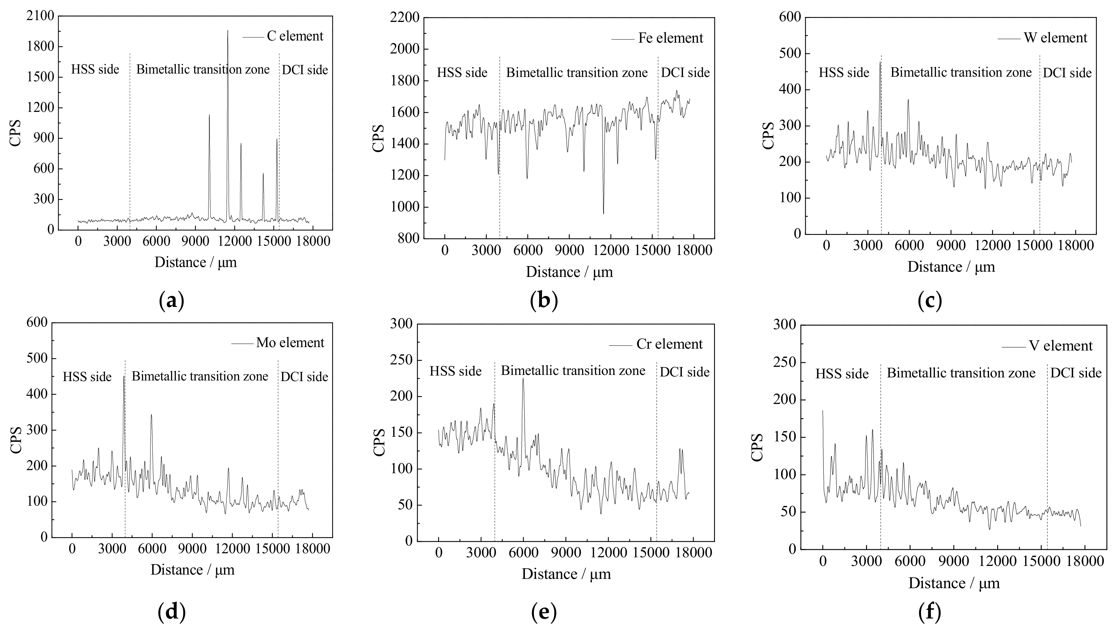
3.5. Elements Distribution in the Bimetallic Bonding Interface

Sample of the bimetallic bonding interface taken from the B1 position in Figure 2 was used to measure the elements distribution of C, Fe, W, Mo, Cr, and V in the bimetallic bonding interface through a line scan analysis. In order to make it be corresponding to the microstructure in Figure 7, width of the tested line for line scan analysis was same as that from Figure 7a–f (a region with continuous change) and the analysis results were shown in Figure 9. The vertical lines for the position of the bimetallic transition zone are consistent with that in Figure 7b,f.
Through the Figure 9, from the HSS side to DCI side, a gradual decrease trend of W, Mo, Cr, and V alloying elements content and a certain width of bimetallic transition zone are obtained. For a detailed description, from 0 to 3000 μm, the contents of the above elements are basically maintained at a constant level, while from 3000 to 12,000 μm, the content of each alloying element changes very obviously due to the diffusion and migration of the alloying elements between high speed steel and ductile cast iron. After 12,000 μm, the content of each alloying element tends to be flat, this is due to the fact that the atomic number of W, Mo, Cr, and V alloying elements are relatively large and their diffusion coefficients are small, meanwhile, the time spent on the bimetallic cladding process is only 42 min (for the total composite height of 264 mm), therefore, the diffusion distance of each alloying element is limited. For C and Fe elements, severe fluctuations in their contents are caused by the sweep of high carbon graphite during the line scan analysis process. At this moment, the peak in the C element spectrum corresponds to the trough in the Fe element spectrum. In addition, it will also lead to a severe decrease of the Fe element content and increase of alloying elements contents when the scanning line passes through the alloy carbides formed by W, Mo, Cr, and V elements. The elements distribution results as shown in Figure 9 is helpful for us to have a good understanding of the formation of different carbides and its containing alloying elements as shown in Table 3 in different positions in the bimetallic bonding interface.

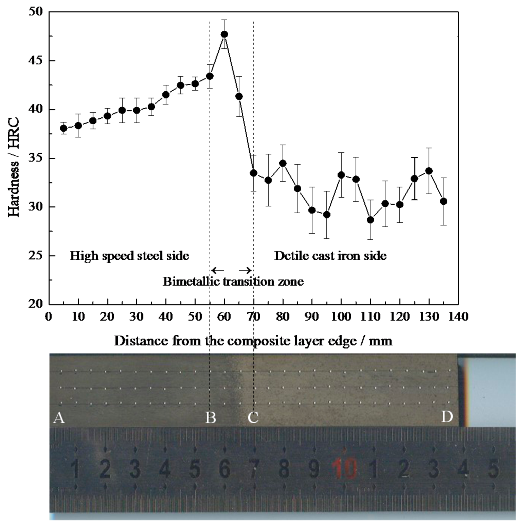
3.6. Hardness Analysis

As we all know, the inhomogeneous microstructure will inevitably affect the mechanical properties, in order to give a further analysis of the mechanical properties changes of the bimetallic transition zone, samples included the bonding interface were taken from the HSS/DCI composite roll in the radial direction and the properties of macro Rockwell hardness and tensile strength were measured.
In the course of our investigation, a rectangular sample with the size of 140 × 20 × 8 mm3 was used for the hardness test and it started at the edge of the composite layer. The measuring distance between two adjacent points in the radial direction was 5 mm, the hardness value of a point was obtained after averaging three measurements as shown in Figure 10.
From Figure 10, it can be seen that, the hardness value increases from 38.1 HRC to 43.4 HRC at the HSS side, this is due to the fact that as the distance from the bimetallic transition zone decreases, the C element diffusion from the DCI side becomes more conspicuously (as the carbon atom is a interstitial atom and the atomic radius is very small, the diffusion speed is fast). With the increase of C content, it is easy to form high hardness MC type carbide with the other alloying elements such as V, W, Mo, and Cr in high speed steel. So, the hardness value shows a trend of gradual increase when it moves from point A to point B.
When coming to the bimetallic transition zone (from point B to point C), a conspicuous change of the hardness value has taken place and it shows a trend of first increasing and then decreasing (43.4 HRC → 47.7 HRC → 41.3 HRC → 33.5 HRC), the maximum hardness value can reach 47.7 HRC and it appears at the bimetallic transition zone near the HSS side. From the previous analysis, a large number of continuous coarse network carbides are formed in the bimetallic transition zone near the HSS side. In addition, these formed carbides are mostly alloy cementite and compound carbides rich for W and Mo elements. While, near the DCI side, only some cementite (eutectic cementite) are formed containing few Mo and Cr elements and a dispersed distribution is obtained. As we all know, the cementite (M3C carbide) has the lowest hardness among the so many types of carbides [15,16], so, the hardness value increases first and then decreases in the bimetallic transition zone.
At the DCI side (from point C to point D), since a large amount of carbon is present in the form of graphite, the formation of cementite is reduced and the hardness of ductile cast iron is reduced too, so the hardness value is maintained around 31.6 HRC.

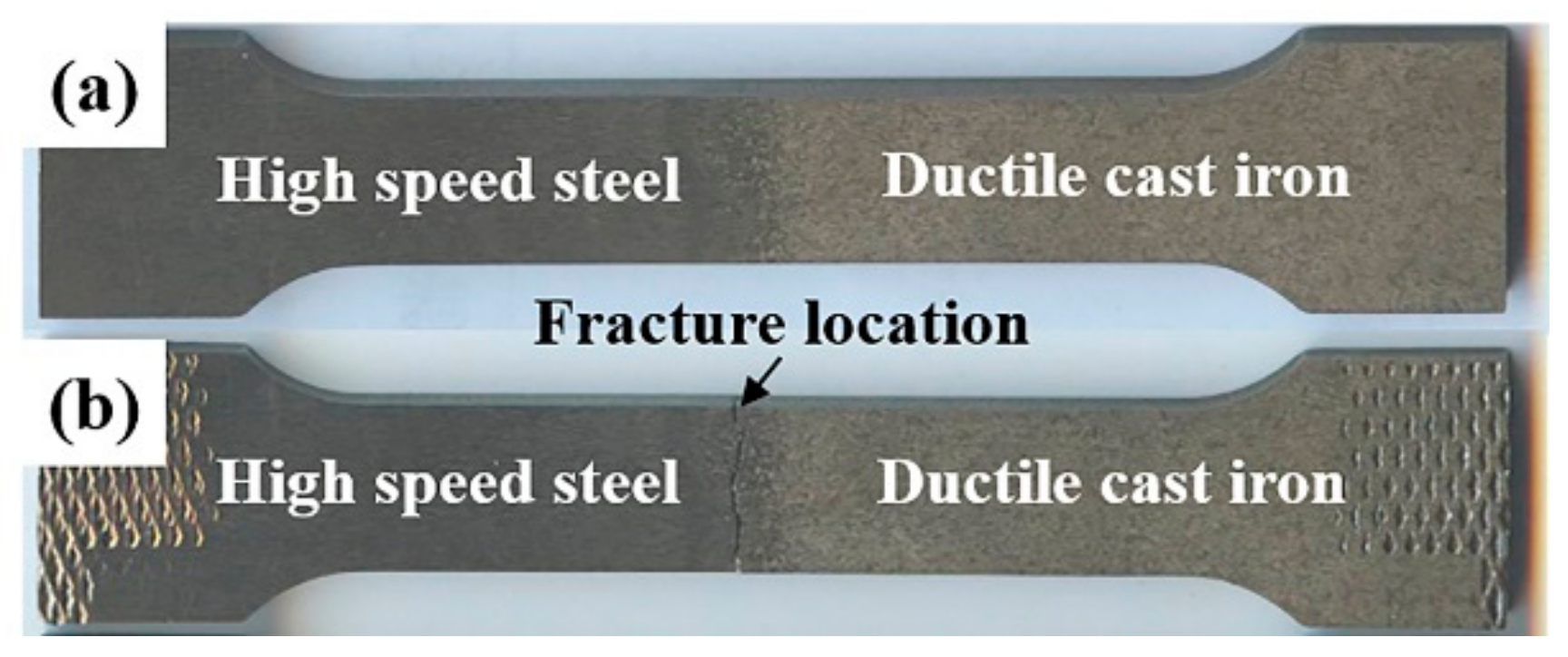
3.7. Tensile Strength Analysis

According to the tensile tests, the tensile strength of the HSS/DCI composite sample is 452 MPa. As there is no corresponding standard for HSS/DCI composite roll, we can’t give a proper evaluation of the tensile strength. As the requirement of tensile strength for cast iron roll is not less than 350 MPa, it is well illustrated that the tensile strength of the HSS/DCI bimetallic composite specimens in the present study is very good.
Figure 11 shows the tensile sample state before and after the tensile test. It shows that the tensile fracture location of the composite sample occurs in the bimetallic transition zone, which indicates that this is a weak zone of the bimetallic composite roll. In addition, it also can be seen that no significant necking occurs before the tensile fracture of the composite sample, which indicates that it has a large brittleness and small plasticity. As a poor plasticity, no significant plastic deformation occurs during the tensile test process.
In order to have a further understanding for the cause of the tensile fracture, microstructure of the fracture location was analyzed by using the DSX510 OLYMPUS metallographic microscope (OLYMPUS Corp., Tokyo, Japan). The results are shown in Figure 12.
Figure 12 shows that the coarse network carbides region in the bimetallic transition zone is more fragile than the fine network carbide and eutectic cementite region, where the tensile fracture occurs. Though the above analysis from the Figure 10, the coarse network carbides region has the maximum hardness value which can help us understand the tensile fracture occurring at this region.
Figure 13 is the tensile fracture at high magnification, under the tensile load, crack initiated and propagated along the coarse network carbides, and finally the fracture occurred as shown in Figure 13.
As the carbides are harder than the matrix, it is more difficult to deform under the tensile load, so, a stress concentration will occur between carbides and matrix which eventually leads to the fracture. Investigations on the hardness analysis of bimetallic bonding interface reveal that it is influenced by microstructural factors as kind, size, volume fraction, distribution of carbides located in the intercellular regions. As most carbides are located along cell boundaries and are much harder than the matrix, microcracks initiate primarily along cell boundaries.

4. Conclusions

The following becomes clear after the investigation on the microstructure and mechanical properties of the bimetallic bonding interface of HSS/DCI composite roll.
(1)
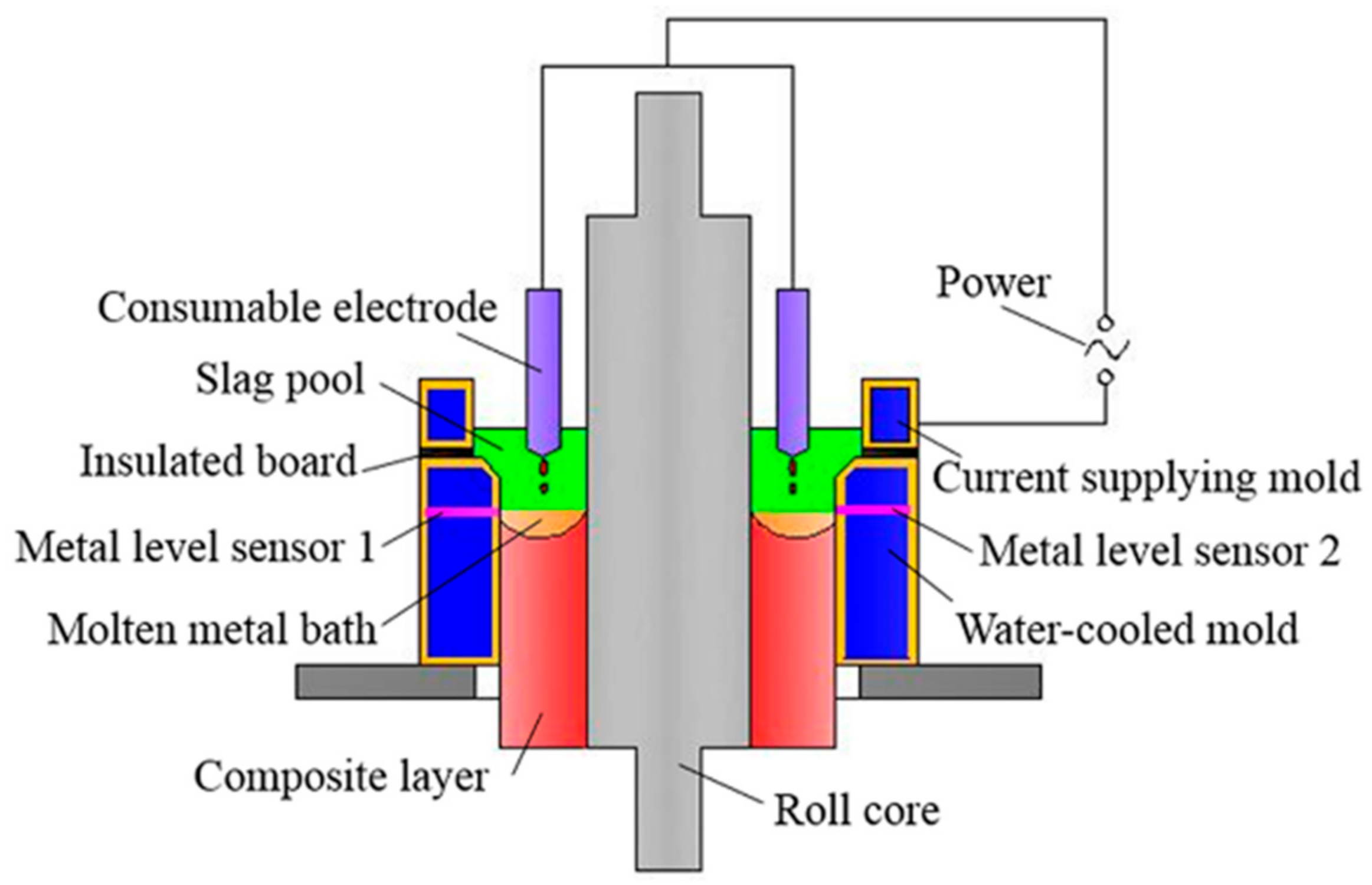
During the electroslag cladding process, the roll core of ductile cast iron was preheated continuously by the heat conduction from the high temperature liquid slag bath as well as the liquid metal of composite layer, therefore, a high temperature austenitizing process have been performed in the heat affected zone (the position near the roll core surface associated with obvious changes of graphite morphology, carbides, and matrix).
(2)
Due to the combined effects of the melting and elements diffusion between high speed steel and ductile cast iron, a large amount of carbides with different morphology, size, and composition generated in the bimetallic transition zone which leads to a trend of first increasing and then decreasing of the hardness value.
(3)
The tensile strength of the HSS/DCI bimetallic composite sample is 452 MPa and it can well meet the requirement of tensile strength for the cast iron roll. However, no significant plastic deformation occurs during the tensile test process due to the large amount of carbides and the tensile fracture occurs in the coarse network carbides region in the bimetallic transition zone.
According to the present study, basic characteristics and microstructure of the bimetallic bonding interface of HSS/DCI composite roll manufactured by the improved electroslag cladding method have been analyzed and a good understanding has been obtained.

Author Contributions

Y.C., Z.J., and Y.D. conceived and designed the experiments; Y.C., Y.D., and X.D. performed the experiments; L.M. and G.S. contributed the metal level sensor and technical consultation about the current supplying mold technology; Y.C. analyzed the data. Y.C. wrote the paper with the support of Z.J. and Y.D.

Funding

This work was supported by National Natural Science Foundation of China (N51274266 and N51674140), Joint Research Fund of National Natural Science Foundation of China and Baosteel Group Corporation (No. U1360103), Fundamental Research Funds for the Central Universities of China (N150202003 and N172507002).

Conflicts of Interest

The authors declare no conflict of interest.

References

  1. Sano, Y.; Hattori, T.; Haga, M. Characteristics of high-carbon high speed steel rolls for hot strip mill. ISIJ Int. 1992, 32, 1194–1201. [Google Scholar] [CrossRef]
  2. Hashimoto, M.; Oda, T.; Hokimoto, K.; Kawakami, T.; Kurahashi, R. Development and application of high-speed tool steel rolls in hot strip rolling. Nippon Steel Tech. Rep. 1995, 66, 82–90. [Google Scholar]
  3. Okabayashi, A.; Morikawa, H.; Tsujimoto, Y. Development and characteristics of high speed steel roll by centrifugal casting. SEAISI Q. 1997, 26, 30–40. [Google Scholar]
  4. Fu, H.G.; Zhao, A.M.; Xing, J.D.; Fu, D.M. Centrifugal casting of high speed steel/nodular cast iron compound roll collar. J. Iron Steel Res. Int. 2002, 9, 32–35. [Google Scholar]
  5. Wang, Z.C.; Fu, H.M.; Li, J.P.; Feng, C.H. Production process of centrifugally cast high speed steel-nodular iron composite roller. Mod. Cast Iron 2009, 29, 44–48. [Google Scholar]
  6. Wu, R.H.; Wu, C.J.; Zhang, X.P.; Gan, Z.P.; Zhao, W.Z.; Chuan, X.Z.; Ma, Y. Effect of heat treatment on property of core of high speed steel-ductile cast iron compound roll. Foundry Technol. 2007, 28, 190–194. [Google Scholar]
  7. Shi, J.W.; Yang, D.X.; Ni, F.; Long, R. Development of high speed steel compound roll. Res. Stud. Foundry Equip. 2005, 27, 28–31. [Google Scholar]
  8. Cao, Y.L.; Jiang, Z.H.; Dong, Y.W.; Deng, X.; Medovar, L.; Stovpchenko, G. Research on the bimetallic composite roll produced by an improved electroslag cladding method: Mathematical simulation of the power supply circuits. ISIJ Int. 2018, 58, 1052–1060. [Google Scholar] [CrossRef]
  9. Lee, D.J.; Ahn, D.H.; Yoon, E.Y.; Hong, S.I.; Lee, S.; Kim, H.S. Estimating interface bonding strength in clad metals using digital image correlation. Scr. Mater. 2013, 68, 893–896. [Google Scholar] [CrossRef]
  10. Cocco, V.D.; Iacoviello, F.; Rossi, A.; Cavallini, M.; Natali, S. Graphite nodules and fatigue crack propagation micromechanisms in a ferritic ductile cast iron. Fatigue Fract. Eng. Mater. Struct. 2013, 36, 893–902. [Google Scholar] [CrossRef]
  11. Shiraki, N.; Usui, Y.; Kanno, T. Effects of number of graphite nodules on fatigue limit and fracture origins in heavy section spheroidal graphite cast iron. Mater. Trans. 2016, 57, 379–384. [Google Scholar] [CrossRef]
  12. Qian, H.C.; Qi, M.D.; Zhao, K.J.; Chen, Y.L.; Shi, C.H.; Lin, X.R.; Lou, J.C. Degradation process of spheroidal graphite in vacuum heated ductile cast iron—Study on spheroidal decline mechanism. J. Chongqing Univ. 1979, 2, 1–15. [Google Scholar]
  13. Fischmeister, H.F.; Riedl, R.; Karagöz, S. Solidification of high-speed tool steel. Metall. Trans. A 1989, 20, 2133–2148. [Google Scholar] [CrossRef]
  14. Zhou, X.F.; Liu, D.; Zhu, W.L.; Fang, F.; Tu, Y.Y.; Jiang, J.Q. Morphology, microstructure and decomposition behaviour of M2C carbides in high speed steel. J. Iron Steel Res. Int. 2017, 24, 43–49. [Google Scholar] [CrossRef]
  15. Gong, K.L.; Dong, Y.J.; Gao, C.L. Research and manufacture of compound high speed steel rolls. Iron Steel 1998, 33, 1–7. [Google Scholar]
  16. Han, J.W. Research on the Microstructural Characteristics and Properties of Cladding Layer and Composite Interface of W6Mo5Cr4V2 High Speed Steel/35CrMo Low Alloy Steel Composite Roll. Master’s Thesis, Jiangsu University, Zhenjiang, China, 2016. [Google Scholar]
Figure 1. Schematic diagram of the new improved electroslag cladding method.
Metals 08 00390 g001
Figure 2. Sampling schematic of roll core, composite layer, and bimetallic bonding interface.
Metals 08 00390 g002
Figure 3. Graphite morphology (a) and microstructure of ductile cast iron (DCI) before the cladding process at low (b) and high (c) magnification.
Metals 08 00390 g003
Figure 4. Graphite morphology (a) and microstructure of DCI after the cladding process at low (b) and high (c) magnification.
Metals 08 00390 g004
Figure 5. Microstructure of the composite layer at low (a) and high (b) magnification.
Metals 08 00390 g005
Figure 6. Graphite morphology in the bonding interface. (ae) → high speed steel (HSS) side to DCI side.
Metals 08 00390 g006aMetals 08 00390 g006b
Figure 7. Microstructure in the bonding interface. (af) → HSS side to DCI side.
Metals 08 00390 g007aMetals 08 00390 g007b
Figure 8. Carbides morphology in different positions of bimetallic transition zone. (af) → HSS side to DCI side.
Metals 08 00390 g008
Figure 9. Elements distribution in the bimetallic bonding interface: (a) C element; (b) Fe element; (c) W element; (d) Mo element; (e) Cr element; and (f) V element.
Metals 08 00390 g009
Figure 10. Hardness test of the bimetallic bonding interface in the radial direction.
Metals 08 00390 g010
Figure 11. The tensile sample state before (a) and after (b) the tensile test.
Metals 08 00390 g011
Figure 12. Microstructure of the tensile fracture of the composite specimen. (a) Towards the HSS side; (b) Fracture position; (c) Towards the DCI side.
Metals 08 00390 g012
Figure 13. The crack initiated and propagated along the coarse network carbides at low (a) and high (b) magnification.
Metals 08 00390 g013
Table 1. Chemical composition of the two materials (wt. %).
Composition in wt.%CSiMnPSCrMoVWNiMgFe
DCI3.302.100.630.0300.0140.640.67--3.200.04Bal.
M2 HSS0.890.370.320.0250.0044.034.761.856.190.19-Bal.
Table 2. Chemical composition of the carbides (wt. %).
PointWMoCrVFe
A42.5136.707.006.327.47
B43.8434.007.018.416.74
C31.3514.762.2748.013.61
Table 3. Chemical composition of the different carbides (wt. %).
PositionPointWMoCrVFe
HSS SideA35.38 20.26 4.11 36.39 3.86
B38.49 34.25 7.23 11.93 8.10
C4.61 5.53 11.26 1.85 76.75
Matrix2.94 1.89 2.77 0.63 91.77
P1A35.0218.093.8240.402.67
B43.28 35.25 4.55 9.86 7.06
C4.92 5.08 10.51 2.33 77.16
Matrix3.01 1.74 3.05 0.52 91.68
P2A41.84 37.851.90 5.55 12.86
B3.25 2.62 6.27 2.55 85.31
Matrix1.92 1.38 1.61 0.25 94.84
P3A22.00 38.52 0.58 0.55 38.35
B2.38 2.99 3.00 1.05 90.58
Matrix3.30 3.99 0.51 0.00 92.20
P4A0.52 1.05 2.69 0.74 95.00
Matrix0.00 0.38 0.66 0.00 98.96
DCI Side(P5)A0.01 75.23 1.97 0.22 22.57
B0.00 2.76 5.96 0.00 91.28
Matrix0.00 1.55 2.35 0.10 96.00

