Article

Surface Quality Improvement of AA6060 Aluminum Extruded Components through Liquid Nitrogen Mold Cooling

1
Dipartimento di Meccanica, Politecnico di Milano, via La Masa 34, 20156 Milano, Italy
2
A.t.i.e. Uno Informatica S.r.l., via Macon 30, 23900 Lecco, Italy
*
Author to whom correspondence should be addressed.
Metals 2018, 8(6), 409; https://doi.org/10.3390/met8060409
Submission received: 5 May 2018 / Revised: 22 May 2018 / Accepted: 29 May 2018 / Published: 1 June 2018
(This article belongs to the Special Issue Casting and Forming of Advanced Aluminum Alloys)

Abstract

:
6xxx aluminum alloys are suitable for the realization of both structural applications and architectural decorative elements, thanks to the combination of high corrosion resistance and good surface finish. In areas where the aesthetic aspects are fundamental, further improvements in surface quality are significant. The cooling of the extrusion mold via internal liquid nitrogen fluxes is emerging as an important innovation in aluminum extrusion. Nowadays, this innovation is providing a large-scale solution to obtain high quality surface finishes in extruded aluminum semi-finished products. These results are also coupled to a significant increase in productivity. The aim of the work is to compare the surface quality of both cooled liquid nitrogen molds and classically extruded products. In this work, adhesion phenomena, occurring during the extrusion between the mold and the flowing material, have been detected as the main causes of the presence of surface defects. The analysis also highlighted a strong increase in the surface quality whenever the extrusion mold was cooled with liquid nitrogen fluxes. This improvement has further been confirmed by an analysis performed on the finished products, after painting and chromium plating. This work on the AA6060 alloy has moreover proceeded to roughness measurements and metallographic analyses, to investigate the eventual occurrence of other possible benefits stemming from this new extrusion mold cooling technology.

Graphical Abstract

1. Introduction

Extrusion is one of the most widely used forming processes for aluminum and its alloys [1,2]. In this process, the internal liquid nitrogen cooling of the extrusion mold represents a significant innovation of recent years [3,4]. Indeed, during the extrusion process, different thermal exchanges occur, for example, heat generation due to material deformation, heat generation due to the friction between the billet and the liner and between the material and the dye, heat generation due to the internal friction between the flowing material and the dead-metal zone, and heat conduction through the components of the system (billet, ram, chamber, dye, etc.). Furthermore, due to the high output speed of this forming technology, the output speed of the is semi-product also high. Thus, the contact time between the mold and the extruded material is very short and the temperature increments are concentrated within a thin surface layer. This will extensively increase the generation of surface defects [5,6,7,8,9,10].
The new liquid nitrogen cooling technology, used directly in the matrix, allows the exploitation not only of the nitrogen inertizing effect, but also of its use as coolant, providing a much broader range of benefits. The liquid nitrogen enters into the channels inside the matrix at a temperature of −196 °C and, during evaporation, it cools the mold. After the change in state, the gas creates an inert atmosphere, which inhibits the formation of oxides. The most significant advantage of this process, which justifies the higher installation and operating costs, is the increase in productivity due to the decrease in heat generation during extrusion. Indeed, the modern liquid nitrogen extrusion mold cooling systems optimize the consumption of nitrogen and guarantee sufficiently precise control over the whole process [3,4,11,12,13]. A schematic sketch of this technology is reported in Figure 1.
Furthermore, both the corrosion resistance and the aesthetic aspect of the final products may be relevant in some application fields of aluminum alloy extruded semi-products. Thus, surface quality may prove to be crucial [14,15,16,17].
Since the temperature increments of the extrusion process are concentrated in a thin surface layer, they drastically affect the surface finishing [2,4,18,19]. It is thus clear that the use of liquid nitrogen cooling of the mold and good temperature control of the overall process will beneficially affect these properties as well.
In the present work, the AA6060 alloy (0.30–0.60 wt % Si, 0.35–0.60 wt % Mg and 0.1–0.3 wt % Fe) is tested. This aluminum alloy is extremely ductile and therefore, is one of the most commonly used aluminum alloys. Further, its mechanical properties can be adjusted by subsequent heat treatment through precipitation hardening. It is used in many technical applications, such as automotive, aerospace and structural frame structures [20,21,22].
This work aims to assess the occurrence of a relationship between the surface quality and the use of internal liquid nitrogen cooling of the extrusion mold. Indeed, for structural frame applications, such as in this case, the extruded surface can be threated via the following aesthetic surface processes that might highlight surface defects. In the present work, in detail, the extruded semi-products undergo a 20 μm painting process and a 1 μm thick chromium plating process (Figure 2).
Thus, all the defects (such as pick-up, dye-lines and blisters), which are not completely hidden within these two overlaying layers, are highlighted in the final products by these aesthetic processes. The surface finishing can accordingly prove a major instance in this application field and even small progresses could emerge as significant.

2. Experimental Procedure

During this work, two main sets of data were collected—one during the production trials of forty semi-finished extruded products, and the other one through laboratory analysis, performed to assess their quality.
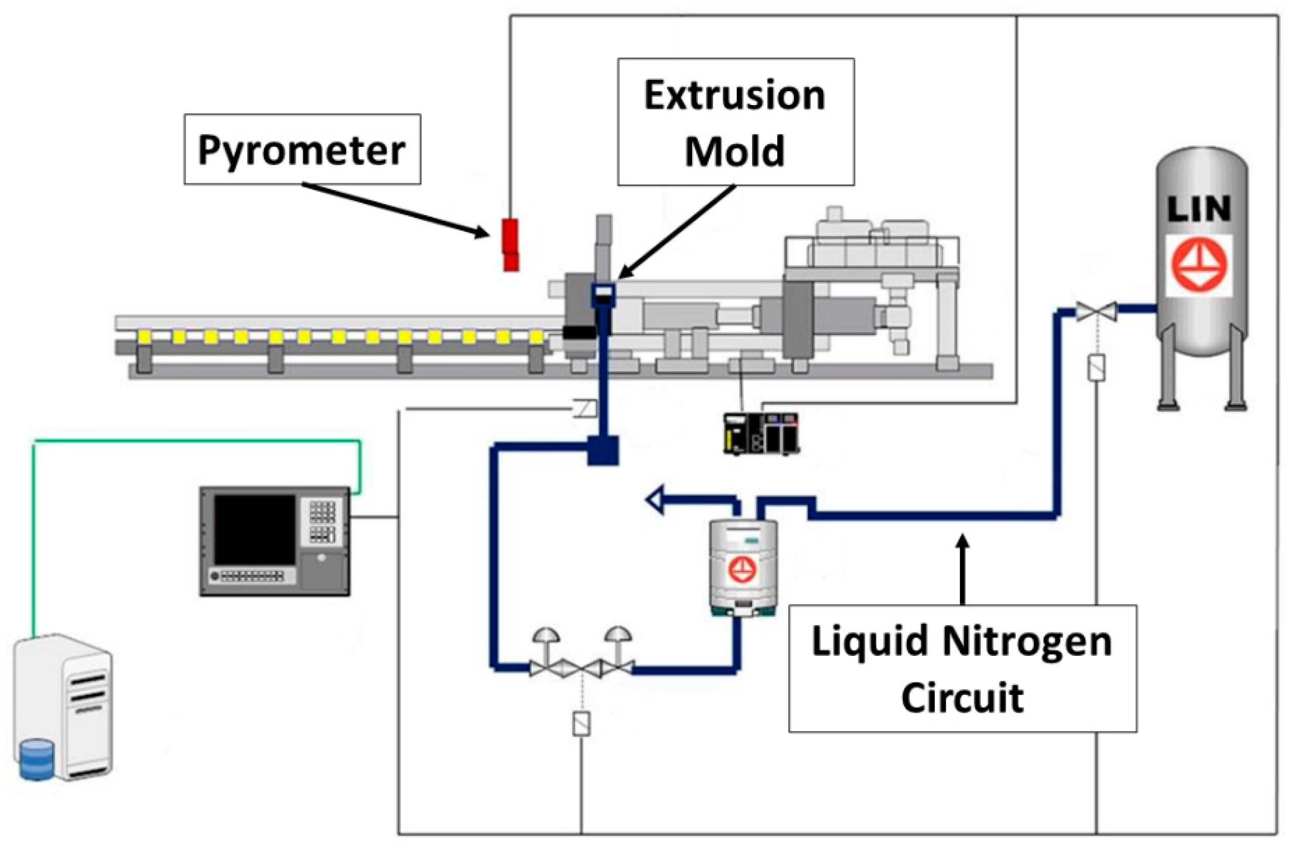
The process parameters were monitored by process-control software, which manages data about material flow speed, temperature and the liquid nitrogen valve opening. In detail, data about dye temperature was collected through four thermocouples (TC) installed within the mold (Figure 3) and two laser pyrometers.
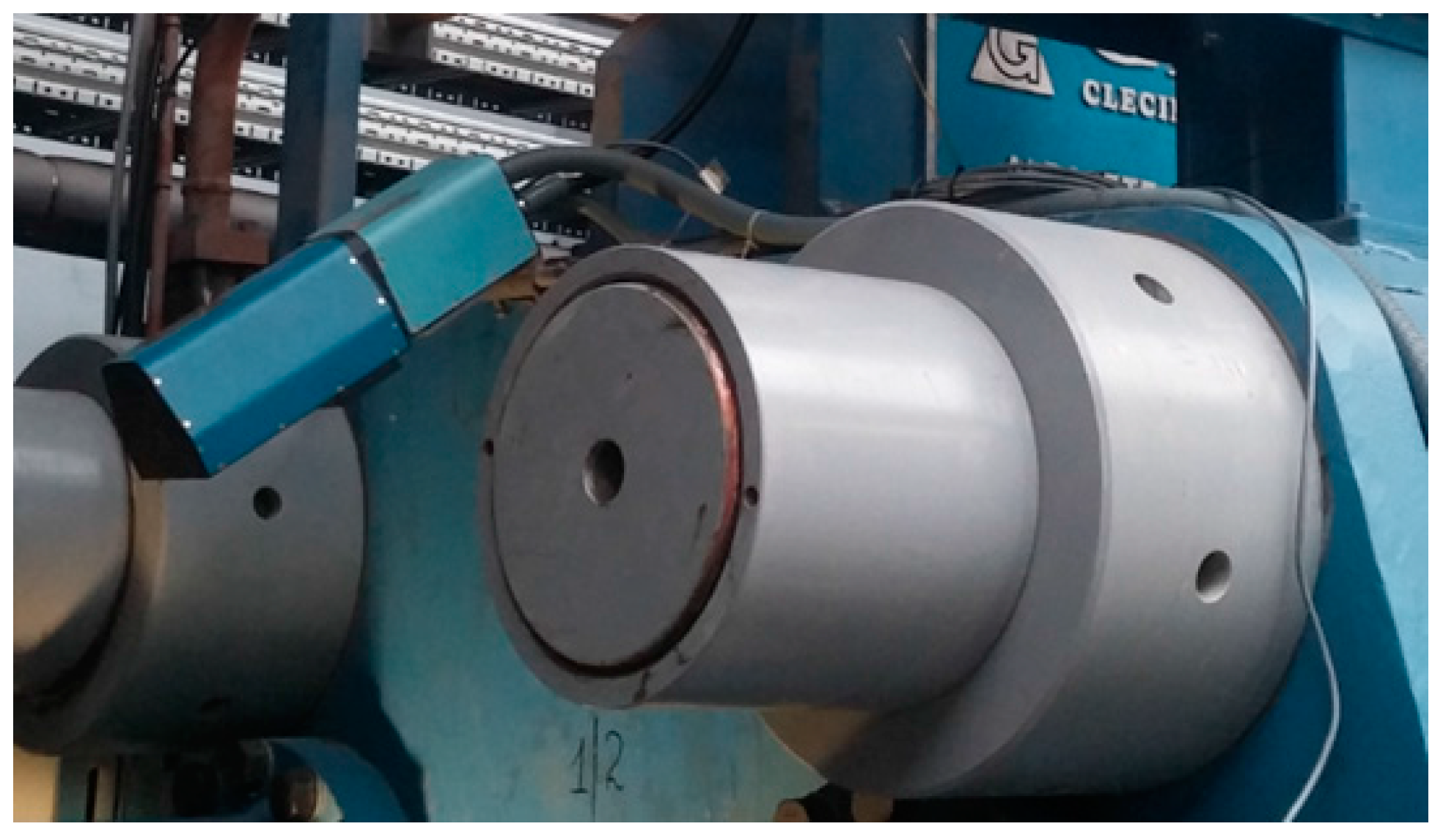
The thermocouples used in this work were Chromel/Alumel (K) thermocouples with mineral oxide insulation and Inconel 600 as the sheath material. The sheath had a 3.2 mm diameter and 2000 mm length. The laser pyrometer temperature method measured the emitted thermal radiation, which directly corresponded to the temperature and surface emissivity of the target. In detail, the pyrometer sensors detected the amount of infrared radiation emitted by the measured object. The pyrometers were installed in front of the exit of the extrusion dye (Figure 4).
On the other hand, the surface defects of the extruded semi-products were characterized in the junction zone of the billets, since this is an accumulation area for the defects [1,2]. The samples were drawn from the extruded semi-products and polished following the common standards. The chemical compositions of the samples were acquired through a scanning electron microscope (SEM) (Carl Zeiss AG, Oberkochen, Germany) Zeiss EVO 50®, using a back-scattered electron (SEM-BSE) (INCA Oxford Instrument, Oxford, UK) detector and energy dispersive X-ray microanalysis (SEM-EDS) (INCA Oxford Instrument, Oxford, UK). In addition, the same instrument was exploited to collect morphological images through a secondary electron detector (SEM-SE) (INCA Oxford Instrument, Oxford, UK).
The samples were etched electrochemically using a Barker’s reagent. The electrolytic solution was prepared by mixing 40 parts of water (H2O) for each volume-part of tetrafluoboric acid (HBF4). The electrochemical anodization was performed by applying a current density of 0.2 A/cm2 (20 V dc) for 40–80 s.
The metallographic analysis was executed using a cross polarized incident light. Afterwards, the index used to evaluate the average grain dimensions was calculated via the Heyn intercept method, following the ASTM E112-13 standard.
Roughness measurements were performed on the surface of the body of the extruded semi-product, hence, not in the junction area. Profile roughness measurements were taken perpendicularly to the extrusion direction, using a stylus Mahr PGK MFK-250® (Mahr GmbH, Göttingen, Germany) tester with a tip radius of 2 μm and a vertical measure range of +/−250 μm. The data were collected following the standard, UNI EN ISO 4288-2000. The translational speed of the measurement was 0.5 mm/s along an exploration length of 5.6 mm. The base length was 0.8 mm and the total evaluated length was 4.0 mm. The collected data were filtered using a Gaussian filter with a wavelength cutter of 0.8 mm.
Surface texture measurements were performed using an Alicona InfiniteFocus® (Alicona Imaging GmbH, Graz, Austria) microscope, which exploits focus-variation technology. The data were acquired in a similar position to those collected for the profile roughness measurements. The surface texture measurements parameters are listed as follows: the total evaluated area measured 4.0 × 4.0 mm and the base length was 0.8 mm. The collected data were filtered again using a Gaussian filter with a wavelength cutter of 0.8 mm.

3. Results

The data collected during the extrusion trials are summarized in Table 1. This sets out the data regarding the most meaningful specimens that were analyzed in this study. It should be underlined that the samples numbered from 1 to 15 were processed through a conventional extrusion, and then, the liquid nitrogen valve was opened and the specimens numbered up to 25 were subjected to transient conditions. Thus, only the semi-products numbered from 26 to 40 were extruded with the liquid nitrogen mold cooling system working at full capacity.
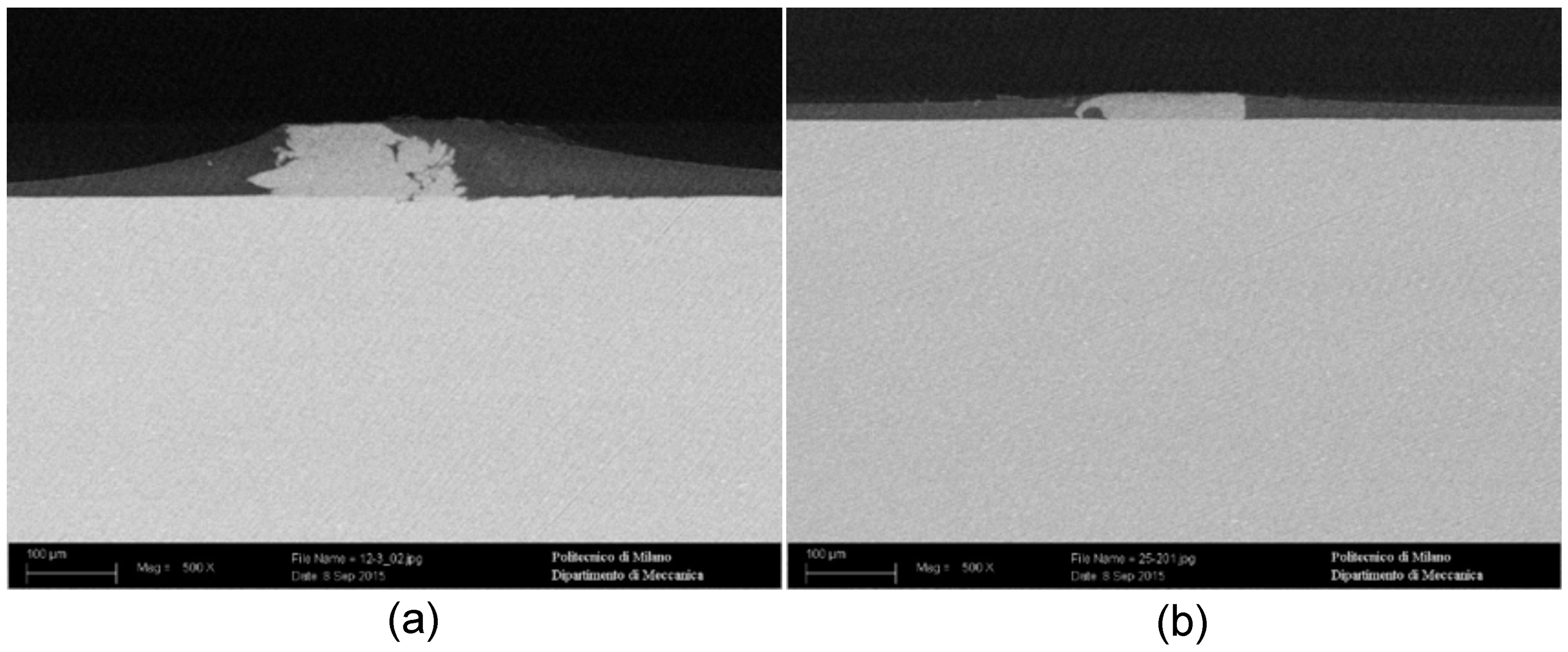
The data regarding the characterization of defects are reported below. Two different species of defects were detected on the surface in the junction area of the extruded semi-products. Their SEM-BSE images are shown in Figure 5, and the acquired chemical compositions are quoted in Table 2.
Therefore, the analyzed defects can be classified as pick-up and dye pick-up. Pick-ups (Figure 5a—point C) are intermittent score lines of varying lengths, which end in a fleck of aluminum debris. They can be easily identified by their chemical composition, which is the same as that of the extruded aluminum alloy [23]. The exogenous deposited layers were composed by a different material and they can be recognized as dye pick-up (Figure 5b—point A, Figure 5a—point A), which are particles worn-out of the extrusion dye and deposited on the semi-product surface [23,24,25,26,27].
Thereafter, the products, subjected to the whole production cycle, including painting and chromium plating, were also analyzed. The typical section, recorded via SEM-BSE, of the surface defects after these processes, is shown in Figure 6. It is worth highlighting that the paint layer does not follow the defect profile; it would thus cover and hide the defects featured by heights up to 15 μm.
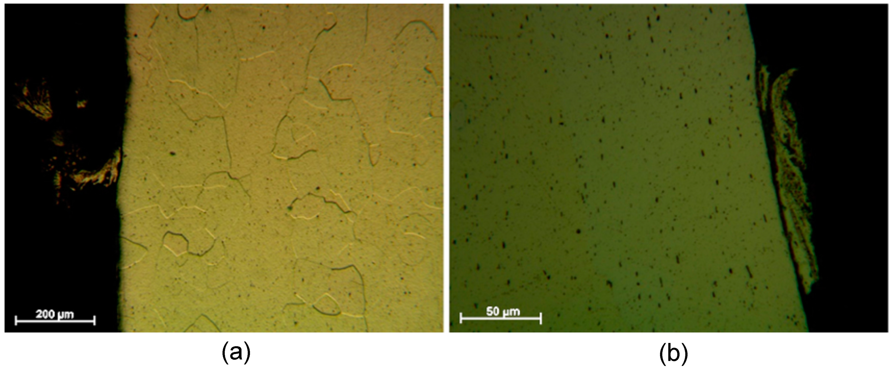
Through optical microscopy, a metallographic analysis was performed on the tested samples. Figure 7 sets out two micrographs obtained after threating the samples via Barker electrochemical etching. However, this analysis did not highlight any detail about the microstructure, which could be relevant or have influence on the generation of defects. Indeed, at the grain boundaries no secondary phase or trace of segregation phenomena is present [28].
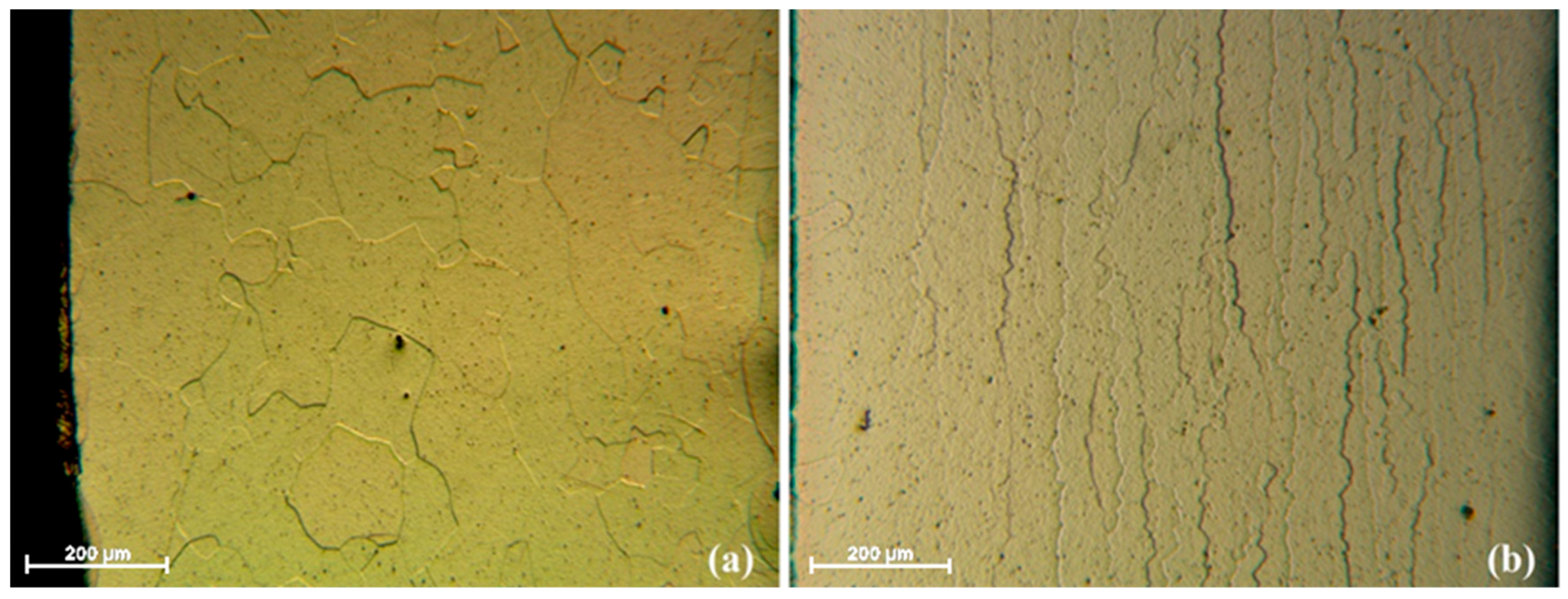
Moreover, the microstructures appeared homogeneous across the junction area sections (Figure 8a). Thus, no relationship between the microstructure and the surface defects was identified. Moreover, no differences in the morphologies of the crystal grains were detected; all the junction areas of the tested specimens featured coarse equiaxial microstructures, without been affected by any variations in the working parameters.
However, few millimeters away from the junction areas, the microstructures of the specimens were very different (Figure 8b). The grains displayed a lamellar structure, oriented along the extrusion direction, usually featuring the extruded semi-products. This occurred because the process arrest leaves the junction area for a much longer time in contact with the mold after being deformed. Thus, a recrystallization phenomenon was promoted, as testified by the loss of the extrusion deformation pattern of the grains [29].
Moreover, the grain size number G, an index measuring the average grain dimensions, was calculated through the Heyn intercept method and the results are reported in Table 3.
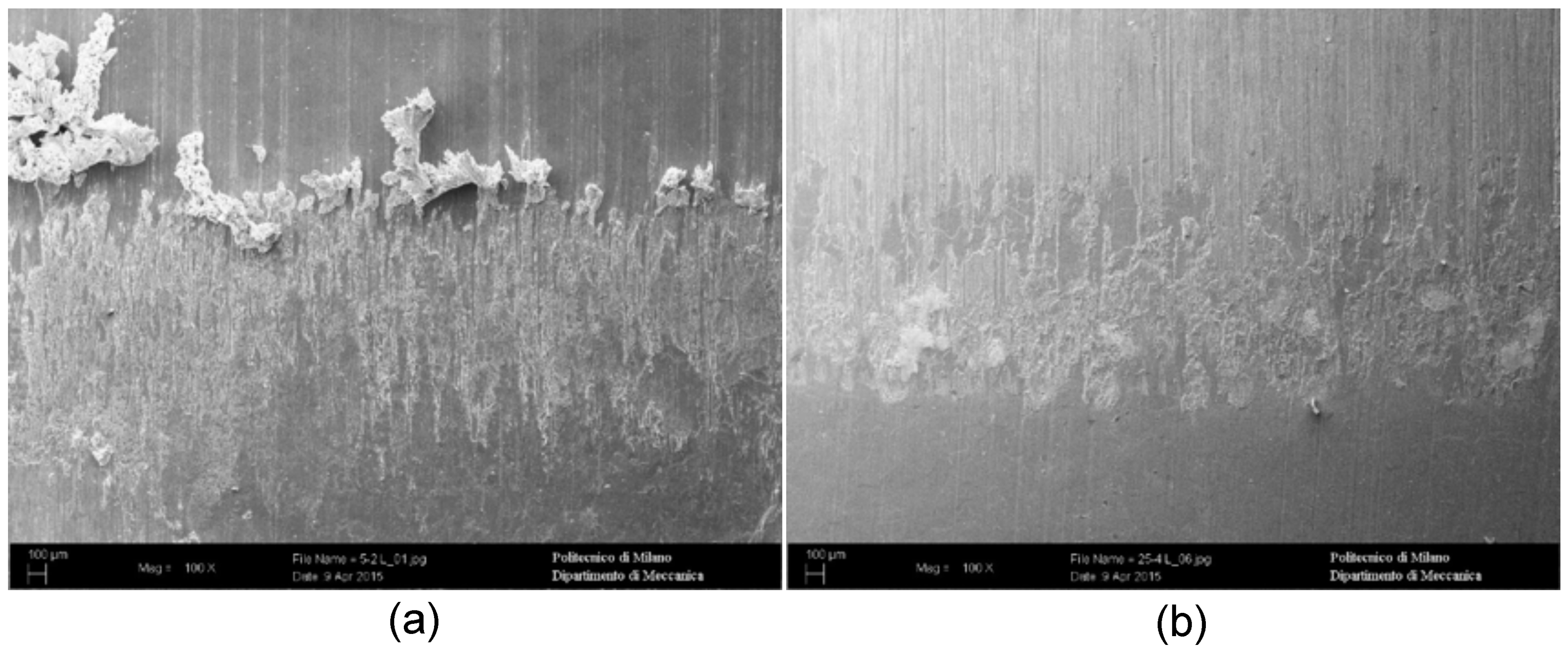
Furthermore, a SEM-SE morphological analysis wasperformed, to qualitatively assess the differences between the different mold cooling methodologies. The most interesting results concerned billets extruded with the same working parameters. In Figure 9, the junction areas of billets 5-2 (air cooled dye) and 25-4 (liquid nitrogen cooled die) are displayed in detail. Compared to the 25-4 sample, the 5-2 specimen showed much larger defects and a large quantity of the material adhered onto the surface.
The results of the roughness tests, performed on the surface of the body of the extruded semi-product—hence not in the junction areas—are shown in Table 4. The mean roughness grew with the mold cooling liquid nitrogen valve aperture during the extrusion trials. On the other hand, the measured maximum roughness displayed a decreasing trend under the same operative conditions.
The surface texture data, collected via microscopy focus-variation technology, are set out below—both the parameters describing the roughness (Table 5) and the height histogram of the surfaces and its statistics (Figure 10 and Table 6). The results are similar to those for the profile roughness. The mean values of the surface roughness slightly increased with use of the liquid nitrogen cooling system. On the other hand, the parameters describing the maxima and the minima of the surface, underwent a decreasing trend with the use of the liquid nitrogen cooling system.
In detail, the skewness values indicated that the height distribution of the liquid nitrogen-cooled sample was more “valley-tailed” than the traditionally extruded surface. For both distributions, the kurtosis parameter highlighted a leptokurtic behavior with a positive excess kurtosis. The higher value of the sample traditionally extruded testifies the presence of larger tails in its height distribution, due to the occurrence of larger surface defects in the sample produced through this technology, as observed via other characterization techniques as well.

4. Discussion

The experimental data from the current study testify that the liquid nitrogen cooling effect is not instantaneous and a transition time is required before a steady working regime temperature can be reached and maintained. This is related to the mold’s thermal inertia. Furthermore, when using this technology, the working temperature becomes lower relative to conventional air cooling of the extrusion mold. However, the differences between temperatures measured at the different dye holes broaden. This phenomenon may be related to the inhomogeneity of the heat removal, linked to the non-optimal sizing of the cooling channel. Therefore, this aspect should be taken into account during the design of the mold, to achieve easy and uniform temperature control [30].
The experimental data regarding the defects analysis in the junction area of the semi-finished extruded billets, found the presence of two varieties of defects. The first featured aluminum flecks of debris adherent to the surface. The chemical composition confirmed that the origin of this debris was the extruded material, since it is identical. The adhesion between the dye and the extruded material generated these defects, as testified by their peculiar morphologies. These defects can thus be recognized as pick-ups [23].
Further to this, a second category of defects was detected and it identified as dye pick-up. This observation was proven by the chemical composition analysis of the deposited material. Indeed, this composition is similar the composition of the AISI H13 tool steel, which is reported in Table 7. Since the extrusion dye is made in this material, its provenance is clearly proved [23,24,25,26,27].
Moreover, any metallurgical origin of the analyzed defects can be excluded. Indeed, both the SEM/BSE analysis and optical microscopy did not detect the presence of any other phases or intermetallic precipitates, any abnormal microstructural features or any abnormal chemical element concentrations. It follows that the origin of the detected defects is linked to wear issues and, in detail, it can be recognized as relating totally to the processing parameters and the tools [23,24,25,26,27].
It should be highlighted that no correlation between the variation of extrusion parameters during the production trials and the species defects were identified. The generation of these kinds of defects would not be totally prevented using liquid nitrogen cooling of the extrusion dye. On the other hand, the occurrence of new defect classes can be excluded by using this technology.
In addition, the liquid nitrogen cooling of the extrusion dyes resulted in a beneficial effect on the amount and on the size of the extrusion defects with patent improvements. Indeed, although the analyzed extrusion defects were few and topologically isolated, the use of this technology further lowered their occurrence and dimensions [11,12].
However, considering their application, in which the aesthetic aspect plays a predominant role, even isolated and very small defects would cause the rejection of the extruded semi-product (Figure 11). Taking into account the further steps involved in the realization of the finished product, we can set the defect acceptance threshold at a height of 15 μm. Indeed, since the paint layer does not follow the defect profile, it could cover and hide these small defects.
Considering this finishing process, the most significant roughness data were those describing the maxima of the roughness measurements of the surfaces and the distribution of the height histogram. These data (Table 4, Table 5 and Table 6 and 
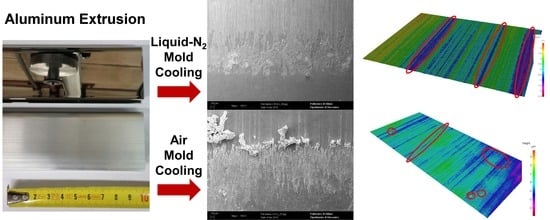
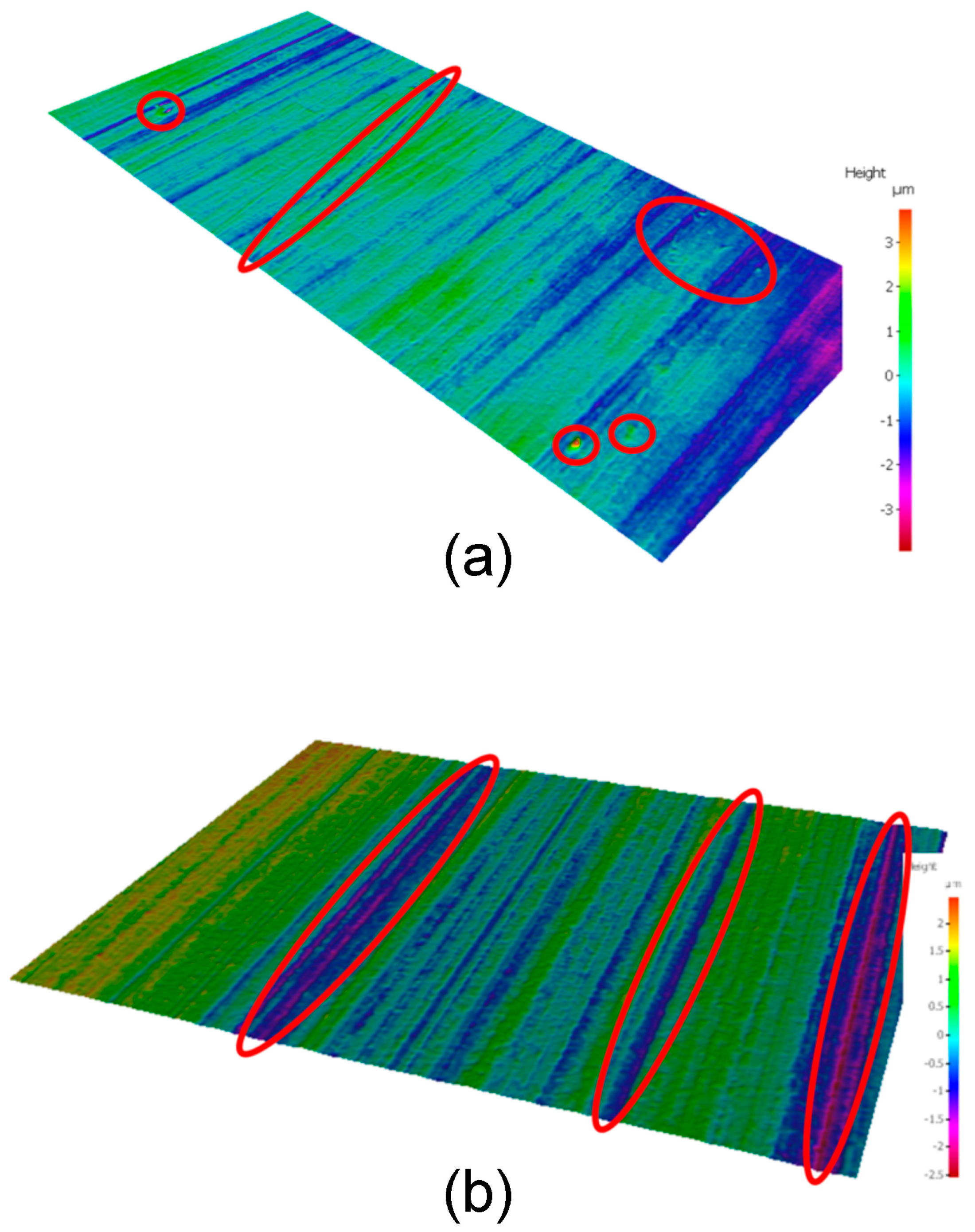
Figure 10) demonstrate the beneficial effect of the liquid nitrogen cooling of the extrusion dye, and an improvement in this key aspect can be appreciated. In addition, the surface roughness maps of the reconstructed surfaces likewise highlight this aspect (Figure 12). The surface of the liquid nitrogen cooled specimen was very smooth and featured valleys along the extrusion direction. On the other hand, on the surface of the conventionally extruded semi-product, peak-like defects were detected emerging from the surface, harming the subsequent finishing processes.
Liquid nitrogen dye cooling technology improves the extrusion process through a complex mechanism, which can be described as follows: the debris, which generates the previously analyzed defects, is in both cases related to the adhesion phenomena occurring during extrusion between the dye and the flowing aluminum. However, this debris is much less present when the liquid nitrogen cools down the mold, even if the measured temperature is the same as for the air cooling. Hence, the improvement in the surface finishing, obtained through the liquid nitrogen cooling technology, is not only related to the lowering of the working temperature.
A different kind of contribution, which could increase the surface finishing, is given by the mechanical action that the nitrogen exerts on the flowing extruded material. Indeed, while absorbing the heat cooling the dye, nitrogen undergoes a phase transformation from the liquid to the gaseous state. This phase transition is known to be accompanied by a very large increase in volume. However, since the cooling circuit is pressured, the phase transformation generates a detaching pressure on the flowing material, which keeps it separated from the mold.
Moreover, liquid nitrogen cooling has another beneficial effect for surface finishing. In detail, it acts as an inert atmosphere enveloping the flowing material, avoiding its oxidation. This plays a central role in wear phenomena, in which aluminum is involved, since its oxide is very easily generated and is extremely hard. On the other hand, in comparison, aluminum is extremely soft and easily damageable with respect to its oxide [4].
Therefore, these beneficial effects on surface finishing, related to the use of liquid nitrogen mold cooling, result from a combination of the cooling effect, the inertizing effect and a mechanical detaching pressure generated by the liquid-to-gaseous transition.

5. Conclusions

Production trials of aluminum alloy extruded semi-products were performed both with conventional air cooling of the extrusion mold and with newly installed liquid nitrogen cooling of the mold. The semi-products analysis led to the identification of two main categories of defects found in the joint areas: pick-up and dye pick-up.
The metallographic analysis pointed out the absence of any hot shortness, grain boundary segregation or coarse intermetallic compound formation phenomena occurring within aluminum semi-finished products as concurrent causes for pick-up generation. The liquid nitrogen dye-cooling did not have any influence on the extruded aluminum grain size. However, the use of liquid nitrogen cooling reduced the adhesion phenomena between the flowing aluminum and the mold, hindering the generation of the detected defects. Moreover, liquid nitrogen dye cooling provided inertizing, detaching and cooling effects. Consequently, the best results, in terms of absence of defects, were achieved at the lowest working temperatures through the use of liquid nitrogen cooling. Furthermore, low working speeds also hindered the generation of defects.
Finally, liquid nitrogen mold cooling, compared to classic air cooling, granted smoother surfaces featured by a high density of valleys along the extrusion direction and the almost complete absence of peak-like defects emerging from the surface which would lead to flaws in the subsequent finishing processes.

Author Contributions

A.F.C., S.B., C.D.C., A.G., L.M. took part to the experimental campaign relative to the metallographic investigation and the defects detection and analysis. C.M. is the research group leader and supervised the work, G.M. and M.B. performed the extrusion an collect the process data using the software produced by A.t.i.e. uno.

Funding

This research received no external funding.

Acknowledgments

This research did not receive any specific grant from funding agencies in the public, commercial, or not-for-profit sectors.

Conflicts of Interest

The authors declare no conflicts of interest.

References

  1. Sheppard, T. Extrusion of Aluminum Alloys; Kluwer Academic Publishers: Norwell, MA, USA, 1999. [Google Scholar]
  2. Saha, P.K. Aluminum Extrusion Technology; ASM International: Materials Park, OH, USA, 2000. [Google Scholar]
  3. Donati, L.; Segatori, A.; Reggiani, B.; Tomesani, L.; Bevilacqua Fazzini, P.A. Effect of liquid nitrogen die cooling on extrusion process conditions. Key Eng. Mater. 2012, 491, 215–222. [Google Scholar] [CrossRef]
  4. Ko, D.-H.; Kang, B.-H.; Ko, D.-C.; Kim, B.-M. Improvement of mechanical properties of Al6061 extrudate by die cooling with N2 gas during hot extrusion. J. Mater. Process. Technol. 2013, 27, 153–161. [Google Scholar] [CrossRef]
  5. Bjork, T.; Bergstrom, J.; Hogmark, S. Tribological simulation of aluminum hot extrusion. Wear 1999, 224, 216–225. [Google Scholar] [CrossRef]
  6. Bastani, A.F.; Aukrust, T.; Brandal, S. Optimisation of flow balance and isothermal extrusion of aluminum using finite-element simulations. J. Mater. Process. Technol. 2011, 211, 650–667. [Google Scholar] [CrossRef]
  7. Ma, X.; De Rooij, M.B.; Schipper, D.J. Modelling of contact and friction in aluminum extrusion. Tribol. Int. 2010, 43, 1138–1144. [Google Scholar] [CrossRef]
  8. Ma, X.; De Rooij, M.B.; Schipper, D.J. Friction conditions in the bearing area of an aluminum extrusion process. Wear 2012, 279, 1–8. [Google Scholar] [CrossRef]
  9. Saha, P.K. Thermodynamics and tribology in aluminum extrusion. Wear 1998, 218, 179–190. [Google Scholar] [CrossRef]
  10. Schikorra, M.; Donati, L.; Tomesani, L.; Kleiner, M. The role of friction in the extrusion of AA6060 aluminum alloy, process analysis and monitoring. J. Mater. Process. Technol. 2007, 191, 288–292. [Google Scholar] [CrossRef]
  11. Celani, P. Liquid nitrogen technology. In Proceedings of the 8th Aluminum Two Thousand International Congress, Milano, Italy, 14–18 May 2013. [Google Scholar]
  12. Ward, T.J.; Kelly, R.M.; Jones, G.A.; Heffron, J.F. The effects of nitrogen—Liquid and gaseous—On aluminum extrusion productivity. JOM 1984, 36, 29–33. [Google Scholar] [CrossRef]
  13. Twigg, R.; Oesterreich, R. Extrud-AlTM—An alternative approach to nitrogen die cooling. In Proceedings of the 8th International Extrusion Technology Seminar, Orlando, FL, USA, 18–21 May 2004. [Google Scholar]
  14. Cotell, C.M.; Sprague, J.A.; Smidt, F.A., Jr. ASM Handbook Vol. 5: Surface Engineering. Surface Engineering of Aluminum and Aluminum Alloys; ASM International: Materials Park, OH, USA, 1994; pp. 784–804. [Google Scholar]
  15. Gali, O.A.; Shafiei, M.; Hunter, J.A.; Riahi, A.R. The influence of work roll roughness on the surface/near-surface microstructure evolution of hot rolled aluminum—Magnesium alloys. J. Mater. Process. Technol. 2016, 237, 331–341. [Google Scholar] [CrossRef]
  16. Rao, K.S.; Rao, K.P. Pitting Corrosion of Heat-treatable Aluminum Alloys and Welds: A Review. Trans. Indian Inst. Met. 2004, 57, 593–610. [Google Scholar]
  17. Rodríguez-Diaz, R.A.; Uruchurtu-Chavarín, J.; Valdez-Villegas, S.; Valdez, S.; Juárez-Islas, J.A. Corrosion Behavior of AlMgSi Alloy in Aqueous Saline Solution. Int. J. Electrochem. Sci. 2015, 10, 1792–1808. [Google Scholar]
  18. De Rooij, M.B.; Ma, X.; Den Bakker, A.J.; Werkhoven, R.J. Surface quality prediction in aluminium extrusion. Key Eng. Mater. 2012, 491, 27–34. [Google Scholar] [CrossRef]
  19. Li, L.; Zhou, J.; Duszczyk, J. Prediction of temperature evolution during the extrusion of 7075 aluminium alloy at various ram speeds by means of 3D FEM simulation. J. Mater. Process. Technol. 2004, 145, 360–370. [Google Scholar] [CrossRef]
  20. Miller, W.S.; Zhuang, L.; Bottema, J.; Wittebrood, A.J.; De Smet, P.; Haszler, A.; Vieregge, A. Recent development in aluminium alloys for the automotive industry. Mater. Sci. Eng. A 2000, 280, 37–49. [Google Scholar] [CrossRef] [Green Version]
  21. Berndt, N.; Frint, P.; Wagner, M.F.-X. Influence of Extrusion Temperature on the Aging Behavior and Mechanical Properties of an AA6060 Aluminum Alloy. Metals 2018, 8, 51. [Google Scholar] [CrossRef]
  22. Tekkaya, A.E.; Schikorra, M.; Becker, D.; Biermann, D.; Hammer, N.; Pantke, K. Hot profile extrusion of AA-6060 aluminum chips. J. Mater. Process. Technol. 2009, 209, 3343–3350. [Google Scholar] [CrossRef]
  23. Garbacz, P.; Giesko, T.; Mazurkiewicz, A. Inspection method of aluminum extrusion process. Arch. Civ. Mech. Eng. 2015, 15, 631–638. [Google Scholar] [CrossRef]
  24. Björk, T.; Westergård, R.; Hogmark, S. Wear of surface treated dies for aluminum extrusion—A case study. Wear 2001, 249, 316–323. [Google Scholar] [CrossRef]
  25. Birol, Y. Analysis of wear of a gas nitrided H13 tool steel die in aluminum extrusion. Eng. Fail. Anal. 2012, 26, 203–210. [Google Scholar] [CrossRef]
  26. Qamar, S.Z.; Arif, A.F.M.; Sheikh, A.K. Analysis of Product Defects in a Typical Aluminum Extrusion Facility. Mater. Manuf. Process. 2004, 19, 391–405. [Google Scholar] [CrossRef]
  27. Arif, A.F.M.; Sheikh, A.K.; Qamar, S.Z.; Raza, M.K.; Al-Fuhaid, K.M. Product defects in aluminum extrusion and their impact on operational cost. In Proceedings of the 6th Saudi Engineering Conference, KFUPM, Dhahran, Saudi Arabia, 14–17 December 2002; pp. 137–154. [Google Scholar]
  28. Wang, L.; Cai, J.; Zhou, J.; Duszczyk, J. Characteristics of the Friction between Aluminium and Steel at Elevated Temperatures During Ball-on-Disc Tests. Tribol. Lett. 2009, 36, 183–190. [Google Scholar] [CrossRef]
  29. Kayser, T.; Klusemann, B.; Lambers, H.; Maier, H.J.; Svendsen, B. Characterization of grain microstructure development in the aluminum alloy EN AW-6060 during extrusion. Mater. Sci. Eng. A 2010, 527, 6568–6573. [Google Scholar] [CrossRef]
  30. Tercelj, M.; Kugler, G.; Turk, R.; Cvahte, P.; Fajfar, P. Measurement of temperature on the bearing surface of an industrial die and assessment of the heat transfer coefficient in hot extrusion of aluminum: A case study. Int. J. Veh. Des. 2005, 39, 93–109. [Google Scholar] [CrossRef]
Figure 1. Schematic drawing of the liquid nitrogen extrusion mold cooling.
Metals 08 00409 g001
Figure 2. Flowchart of the production process of extruded AA6060 structural frames.
Metals 08 00409 g002
Figure 3. Schematic drawing of the thermocouples’ positions within the dye.
Metals 08 00409 g003
Figure 4. Pyrometers’ positions.
Metals 08 00409 g004
Figure 5. SEM-BSE images of extrusion defects detected in the junction area of the billets: sample 5 (a), sample 13 (b). A, B, C are the point in which the chemical analysis was performed (Table 2).
Metals 08 00409 g005
Figure 6. SEM-BSE images of sections of the final products defects: sample 12 (a), sample 25 (b).
Metals 08 00409 g006
Figure 7. Micrographic analysis of the pick-ups presents within the defect area the specimen 5 (a) and specimen 33 (b).
Metals 08 00409 g007
Figure 8. Micrographic analysis of sample 9 in the junction area (a) and in a different area representative of the rest of the semi-product (b).
Metals 08 00409 g008
Figure 9. SEM-SE morphological analysis of the junction areas of the billets comparing one produced through an air cooled die 5-2 (a) and one produced via the liquid nitrogen cooled die 25-4 (b).
Metals 08 00409 g009
Figure 10. Height histogram of the samples’ surfaces: traditionally extruded (specimen 5) and the liquid nitrogen cooled (specimen 37).
Metals 08 00409 g010
Figure 11. Semi-finished (a) and finished (b) products: the production cycle, after extrusion, is completed by brushing, acid degreasing, painting and chromium plating.
Metals 08 00409 g011
Figure 12. Surface roughness maps. The surface of the conventionally extruded semi-product (a) is featured by peak-like defects emerging from the surface. The surface of the liquid nitrogen cooled specimen (b) features the presence of valleys along the extrusion direction.
Metals 08 00409 g012
Table 1. Data featuring the extrusion trials of the specimens. Samples 5, 9, 13 were extruded conventionally. Samples 21 and 25 were processed during the transition step. Specimens 33 and 37 were extruded when the liquid nitrogen mold cooling worked at full capacity. The thermocouples (TC) were positioned within the mold as reported in Figure 3.
SampleBillet Average Speed (m/min)Billet Average Temperature (°C)TC1 (°C)TC2 (°C)TC3 (°C)TC4 (°C)Liquid Nitrogen Valve Aperture (%)
515.945265185074975270
917.065345275145035340
1319.625455285165055380
2122.1852850448248252260.46
2516.7452847945645050520.05
3315.6451147444744749711.72
3715.5150646343944148527.08
Table 2. SEM-EDS chemical analysis of the areas highlighted in Figure 5, the element concentrations are expressed as wt %.
Area% Mg% Al% Si% S% V% Cr% Mo% Fe
5-1 L_05_A-3.892.501.472.119.67-80.36
5-1 L_05_B0.5898.870.55-----
13-3 L_02_A-2.382.67-1.7311.263.1278.76
13-3 L_02_B0.5797.640.49-----
13-3 L_02_C0.7598.680.57-----
Table 3. Grain size number (G) index.
SampleExtrusion Mean Temperature (°C)G (NL/mm)
552614
953413.5
1354514.5
2152814
2552814
3351114
3750614
Table 4. Roughness tests results (Ra: Roughness Average; Rz: Average Maximum Height of the Profile; Rmax: Maximum Roughness Depth).
SampleRa (μm)Rz (μm)Rmax (μm)
130.403.024.31
250.4445.12
330.533.543.89
Table 5. Surface roughness parameters.
ParameterDescription(u)Sample
537
SaAverage height of selected areanm361471
SqRoot-mean-square height of selected areanm467587
SpMaximum peak height of selected areaμm1.991.41
SvMaximum valley depth of selected areaμm3.982.48
SzMaximum height of selected areaμm5.973.89
S10zTen-point height of selected areaμm4.663.80
SskSkewness of selected area −0.45−0.78
SkuKurtosis of selected area 3.693.13
SdqRoot mean square gradient 0.080.09
SdrDeveloped interfacial area ratio%0.340.44
FLTtFlatness using least squares reference planeμm5.973.89
Table 6. Statistics of the height histograms of specimens’ surfaces.
Height Histogram Statistics(u)Sample
537
Number of Elements 8,816,4148,253,132
Classes 120195
Class Widthμm0.050.02
Mean Valueμm0.0186−0.0225
Standard Deviationμm0.46670.5870
Minimum Valueμm−3.9756−2.4777
Maximum Valueμm2.02441.4233
Table 7. Extrusion dye material (AISI H13 tool steel) chemical composition, as designed by standards, the element concentrations are expressed as wt %.
Steel% C% Si% Mn% Ni% V% Cr% Mo% Fe
AISI H130.401.00.40.31.05.01.5Bal.

