Mechanical Properties and Corrosion Behavior of WZ73 Mg Alloy/SiCp Composite Fabricated by Stir Casting Method

Department of Mechanical Engineering, National Taiwan University of Science and Technology, Taipei 106, Taiwan
*
Author to whom correspondence should be addressed.
Metals 2018, 8(6), 424; https://doi.org/10.3390/met8060424
Submission received: 5 May 2018
/
Revised: 28 May 2018
/
Accepted: 1 June 2018
/
Published: 5 June 2018
Abstract
:Low strength, which limits the industrial applications of Mg alloys, can be improved by forming Mg-based metal matrix composites (MMC) reinforced with ceramic particles. In this study, a Mg-based MMC was synthesized by introducing SiC particles into a WZ73 Mg alloy using the stir casting method. The effects of the SiC particles on the mechanical properties and corrosion behavior of WZ73 alloys were studied. The results showed that an addition of 1.5 vol % of SiC enhanced the strength of a WZ73 alloy but reduced the corrosion resistance. A further increase of SiC to 2.5 vol % had no effects on strength and corrosion behavior, which was attributed to the agglomeration of SiC particles. A microstructural analysis indicated that the addition of SiC did not alter the morphology and distribution of the secondary phase in the WZ73 alloy. Thus, the improved strength was attributed to the reinforcement of SiC and the refinement of the Mg grain, while the degraded corrosion resistance was the result of the grain refinement of Mg and the presence of the Mg/SiC interface in the vicinity of the secondary phase, which breaks the continuity of the Mg matrix and results in a higher corrosion rate.
1. Introduction
In recent years, the demands for light-weight structural materials with high specific strength to weight ratio and recyclability have increased dramatically in the automotive and aerospace industries [1,2,3,4]. Magnesium and its alloys are potential candidates to meet the abovementioned requirements. However, inferior properties such as low strength, and corrosion resistance have limited their industrial applications [5,6].
Properties of Mg alloys can be controlled by the addition of different kinds of alloying elements. The conventional Mg alloys including AZ and ZK series Mg alloys are produced by adding alloying elements such as Al, Zn, and Zr. The other approach to adjusting the mechanical properties of Mg alloys is by adding reinforcement to form Mg-based metal matrix composite (MMC) materials. The performance of a MMC is strongly affected by both the matrix and reinforcement. Recently, the addition of rare earth (RE) elements has been extended to conventional Mg alloys having Zn as the principle alloying element. With the addition of RE, especially yttrium (Y), the mechanical properties of Mg alloys are improved. Among the Mg-Zn-RE system, WZ series alloys (Mg-Y-Zn) have attracted much attention because of their unique long period stacking ordered (LPSO) structure, which improves both strength and corrosion resistance [7,8,9,10]. Kawamura et al. synthesized the WZ73 (Mg97Y2Zn1 in at %) alloy by the rapidly solidified powder metallurgy (RS/PM) method [11]. An ultra-high tensile strength of 610 MPa and a modest failure strain of 8% was obtained for this Mg-Y-Zn alloy containing a LPSO structure. Later research has shown that the WZ73 alloy with LPSO structure can also be produced by the conventional casting method [12]. Therefore, the WZ73 alloy is a promising material for matrix.
As for reinforcement materials, research objectives for MMCs were mainly focused on continuous fiber reinforcement in the early stages MMCs development. However, because of the complex manufacturing process and the relatively high cost of fibrous MMCs, more and more studies have been focused on using discontinuous particles as a reinforcement [13]. With a high melting point, high hardness, and thermal stability ceramic particles such as SiC, Al2O3 have been widely utilized as reinforcements. The properties of Mg-based MMCs reinforced with SiC particles (SiCp) or Al2O3 particles (Al2O3p) have been extensively studied. However, regarding the selection of matrix materials, almost all of the matrix materials in the investigated MMCs were limited to conventional AZ or ZK series Mg alloys. Only a few researches have reported on MMCs with Mg-Zn-Ca, Mg-Nd-Zn, and Mg-Zn-Y-Al alloys as matrix materials [14,15,16]. Therefore, it is necessary to study the performance of novel MMCs that combine both of the advantages of a novel Mg alloy matrix and reinforced ceramic particles.
The effects of the reinforcement on the secondary phase in the matrix material should also be considered when designing Mg-based MMCs. Tan et al. reported the mechanical properties of a Mg-Y-Zn-Al/Al2O3 composite prepared by the disintegrated melt deposition (DMD) method [16]. The mixtures of Mg97.76Y1.06Zn0.76Al0.42 (at %) and 0.5, 1.0 and 1.5 vol % of nano-Al2O3 particles were melted at 750 °C and then disintegrated by jets of argon gas and deposited into a steel mold. It was found that the LPSO phase (Mg12YZn) no longer existed in the as-cast alloys after adding nano-Al2O3 particles, indicating nano-Al2O3 particles inhibited the formation of the LPSO phase during solidification. With the absence of the LPSO phase, the strength of the composite decreased while the failure strain increased. Thus, it is necessary to explore whether the addition of SiC particles into the WZ73 will eliminate the LPSO phase in the WZ73-SiC MMC since the LPSO phase is the key factor for the enhanced mechanical properties in WZ73 alloy.
Nowadays, MMCs with ceramic particles as reinforcement materials have been produced by stir casting, squeeze casting, spray deposition, disintegrated melt deposition, and powder metallurgy [17]. The selection of a processing method depends on factors including production cost, required porosity level, less chemical reactivity during processing, mass production capacity. Among these processing methods, stir casting is flexible, commercially applicable, and has a low production cost [18]. Thus, stir casting was used to fabricate WZ73-SiC MMC in the current study.
In addition to mechanical properties, the corrosion resistance of Mg alloys and Mg-based MMCs needs to be improved. Zhao et al. reported the corrosion behavior of Mg-Y-Zn alloys containing a LPSO structure [19]. The LPSO phase with a morphology of a continuous network in the grain boundary region could act as a corrosion barrier to protect the matrix. With a proper control of volume fraction and distribution of the LPSO phase, the Mg-Y-Zn alloy exhibited a lower corrosion rate than conventional engineering Mg alloys. For the corrosion behavior of Mg-based MMCs reinforced with SiCp, most of the studies have focused on the pure Mg-based, and AZ and ZK series-based MMCs [20,21,22,23]. The results suggested that galvanic corrosion between the Mg matrix and SiC reinforcement in Mg-based MMC was negligible. SiC resulted in the grain refinement of Mg and the nucleation of the secondary phase, enhancing microgalvanic corrosion. Moreover, with the addition of SiC, less protective surface films were formed, which accelerated the corrosion rate. However, compared to studies of the corrosion behavior of conventional AZ and ZK-based MMCs, very few studies have been performed on novel Mg-based MMCs.
Literature reviews revealed that no prior attempts have been made to introduce SiC particles into a LPSO-containing WZ73 alloy. Accordingly, the aim of the present study is to fabricate the WZ73-SiC MMC using a stir casting method and to provide an early insight on the WZ73-SiC system by first investigating the effects of the SiC addition on the elimination of the LPSO phase, mechanical properties, and corrosion behavior of WZ73 alloy. The effects of SiC will be investigated in terms of grain size of the Mg matrix, as well as morphology, volume fraction, and distribution of the LPSO phase.
2. Materials and Methods
The WZ73 Mg alloy (90.7Mg-6.8Y-2.5Zn in wt %; Mg97Zn1Y2 in at %) was prepared by melting commercial pure Mg (99.98 wt %), Zn (99.9 wt %) and Y (99.9 wt %) ingots in an electric resistant furnace under the protection of a mixture gas (99% CO2 and 1% SF6) at 750 °C. After mechanical stirring at 400 rpm for 15 min, the molten alloy was poured into a steel mold preheated at 200 °C and air cooled. Mg-based MMCs were fabricated by stir melting the WZ73 alloy with 1.5 and 2.5 vol % of SiC particles (SiCp), having an average particle size of 10 μm using the same parameters, except for a longer stirring time of 25 min. After casting, an ingot having a diameter of 70 mm and a height of 170 mm was obtained. For the WZ73 alloy, the top and bottom portion with a height of 20 mm, containing a large amount of oxide inclusions, were discarded. Only the middle portion was used for further analysis. However, the same technique could not effectively eliminate oxide impurities in the MMC. Oxide impurity is still observed in the middle portion of the MMC ingot. The reason will be discussed in detail in Section 3.1.
The microstructural characterization of the samples was conducted with an optical microscope (OM) and a field-emission scanning electron microscope (FE-SEM) equipped with Energy Dispersive Spectroscopy (EDS). The volume fraction of phases in the samples were measured using Image J software. Five random locations of each alloy were analyzed. The constituent phases in the samples were examined by X-ray diffraction (XRD) using Cu Kα radiation with the scan range of 20 to 80°. The data were collected with a step size of 0.02° and time of 0.5 s. The LPSO phase was identified using the XRD pattern of as-cast Mg97Zn1Y2 alloy reported by Yamasaki et al. [24]. A room-temperature tensile test was performed using a universal material testing machine. For each condition, three rectangular samples with the gauge size of 20 mm × 5 mm × 3 mm were tested. The fracture morphology was observed using FE-SEM. Vickers microhardness tests were performed using a load of 100 g at a 15 s dwell time. At least ten readings were made from which the mean value was calculated.
The corrosion performance was analyzed by the immersion test. Immersion tests were conducted in 1 wt % NaCl solution at room temperature for 24 h. Approximately 60 mL solution per cm2 specimen surface was used during the test. Surfaces of rectangular samples with a dimension of 10 mm × 10 mm × 6 mm were ground with SiC sandpaper up to 2500 grit, then ultrasonically cleaned in alcohol and dried. After immersion periods of 1, 12, and 24 h, the samples were removed from the solution, cleaned and dried. The corrosion surfaces of the samples were observed using a digital camera and a SEM. The composition of the corrosion products was analyzed by EDS and XRD. Thereafter, the corrosion products on the samples were removed and the masses of samples were recorded. The corrosion rates were calculated by the mass loss according to the following formula [25]:
where CR is the corrosion rate, Δm is the mass loss in g, A is the surface area of the sample in cm2, t is the immersion time in h, and ρ is the density of the sample in g/cm3.
CR (mm/year) = (8.76 × 10 4 × Δm)/(A × t × ρ)
3. Results and Discussion
3.1. Microstructural Characterization
Optical and SEM micrographs of the as-cast WZ73 alloy, WZ73-1.5 vol % SiC and WZ73-2.5 vol % SiC composites are shown in Figure 1. EDS analysis was performed on selected areas shown in Figure 2. The results given in Table 1 indicate that zone 1 (matrix) is α-Mg solid solution with a relatively low content of Zn and Y, and zone 2 (secondary phase) is a phase with a relatively high content of Zn and Y, which can be assigned to Mg12Z1Y1 (at %) phase with a LPSO structure as reported in Refs [9,10,26,27] (Table 1). In MMCs, Zone 3 can be identified as SiC, while zone 4 located at the interface of the matrix and second phase, is a region having a slightly higher amount of Zn and Y than those in the matrix (Figure 2a,b). An agglomeration of SiC particles together with oxide impurity (zone 5 with an enriched Y content, which is most likely Y2O3 identified by the XRD analysis shown in Figure 3) in MMCs is observed. The corresponding XRD patterns confirm the presence of the α-Mg and the LPSO phase in the WZ73 and MMCs, as well as the presence of SiC in MMCs. The LPSO phase in the samples has a 18R-type structure reported by Yamasaki et al. (Figure 3) [24].
Oxide inclusion is one of the major defects found in MMCs prepared by stir casting. The formation of Y2O3 in MMCs is due to the oxidation of Y caused by the prolonged stirring time in the casting process. During the melting of the WZ73 alloy, a protective surface film on the molten alloy surface is formed with the help of a mixture gas containing SF6 and CO2. However, the stirring will break the thin surface film and cause the oxidation of alloying elements, especially for Y. The stirring time of 15 min is optimized to control the formation of oxides for preparing the WZ73 alloy using the current melting furnace. With a stirring time beyond this limit, Y2O3 is clearly identified by XRD and SEM analysis. However, a prolonged stirring time is needed to have a better distribution of SiC in the WZ73 alloy. With the increased time, the tendency of oxidation of Y is increased and thus Y2O3, which is not detected in the WZ73 alloy, is clearly observed in the MMCs. In the further study of MMCs containing Y, casting methods with a lower tendency of forming oxide impurities should be considered.
The WZ73 alloy consists of a primary dendritic matrix and a secondary phase distributed in the interdendritic regions. In MMCs, the morphology of α-Mg region changes from a dendrite to more rounded shape after adding SiC. The SiC particles are located in the vicinity of the LPSO phase.
The morphology of the LPSO phase in the WZ73 alloy can be described as a semi-continuous network with a small amount of isolated islands. With the addition of SiC, the morphology of the LPSO phase does not change in the MMCs. The average grain size of α-Mg in each alloy is given in Table 2. Grain size decreases from 143 μm in WZ73 alloy to 118 μm in WZ73-1.5 vol % SiC, and 114 μm in WZ73-2.5 vol % SiC, indicating a grain refinement after the addition of SiC. The grain refinement is due to the heterogeneous nucleation introduced by the SiC particle. After the addition of SiC, the solid/liquid interface energy is reduced, and nuclei can be formed more easily. Additionally, it seems that increasing the amount of SiC from 1.5 vol % to 2.5 vol % in WZ73 has no effect on grain refinement. This might be the result of an agglomeration of SiC particles.
3.2. Mechanical Properties
The yield strength (YS), ultimate tensile strength (UTS), elongation, and volume fraction of the phases of the tested samples are given in Table 2. YS and UTS of the WZ73 alloy are 126 and 172 MPa, respectively, while the YS and UTS of the WZ73-1.5 vol % SiC are 160 and 223 MPa, respectively. With the addition of SiC, the YS and UTS of the WZ73 alloy increase. The YS and UTS of the WZ73-2.5 vol % SiC are 154 and 238 MPa, respectively. A further increase of SiC content to 2.5 vol % does not affect the YS and UTS of MMC. The elongation of the MMCs (6%) is lower than that of the WZ73 alloy (9%), indicating that the addition of SiC has a negative impact on the elongation of the WZ73 alloy, which is well known for particulate reinforced MMCs.
Possible effects of SiC on mechanical properties can be discussed based on its effect on the grain size of α-Mg and volume fraction, morphology, distribution and type of LPSO phase. It has been reported that the introduction of ceramic reinforcements into Mg alloys refined the grain size of Mg [13]. The shape of the LPSO phase, whether it is a semi-continuous network or a zigzag morphology, had influence on the properties of WZ series alloys. The LPSO phase fully grown into the Mg grain region was more effective on strengthening than the one located at the grain boundary [26]. In the WZ series alloys, room-temperature yield strength increased with the increase of the volume fraction of the LPSO phase [28]. Whether the addition of SiC will affect the Mg grain size and the properties of the LPSO phase must be explored, since these two factors are related to the mechanical properties of MMCs.
Grain size decreases after the addition of SiC. According to the Hall–Patch equation, the strength increases as the grain size decreases. The grain refinement in the MMCs is expected to increase the strength when compared with that of the WZ73 alloy. The hardness values of the LPSO phase (115 HV) and SiC are higher than that of α-Mg (77 HV). As a result, the role of the LPSO phase and SiC in tested alloys can be treated as the reinforcement while α-Mg can be seen as the matrix in the alloy. The volume fraction of the LPSO phase decreases from 22.8% in the WZ73 alloy to 19.7% in the WZ73-1.5 vol % SiC, and 15.9% in the WZ73-2.5 vol % SiC. The YS and UTS are expected to decrease with the decrease in the volume fraction of the LPSO phase in MMCs. However, the YS and UTS values of the MMCs are higher even though the volume fraction of the LPSO phase is lower in the MMCs. Therefore, contributions from the grain size strengthening and dispersion strengthening of SiC to YS and UTS have prevailed over weakening effects arising from the decrease of the LPSO phase, and potentially form the particle clustering of SiC.
The effect of a morphology change of the LPSO phase on the mechanical properties of the WZ series Mg alloys was studied by Chen et al. [26]. It was reported that the fully-extended LPSO phase, which had a lamellar structure through the entire matrix region, was beneficial for the improvement of YS and UTS. However, for the WZ73 alloy and MMCs in the current study, the extension of the LPSO phase is limited to the vicinity of the LPSO phase region. Thus, the influence of the morphology change on the strength is less effective in the present work. Mg-Y-Zn-Al/Al2O3 composites were prepared by a disintegrated melt deposition of mixtures of Mg97.76Y1.06Zn0.76Al0.42 (at %) and 0.5, 1.0 and 1.5 vol % of nano-Al2O3 particles [16]. It was found that the LPSO phase (Mg12YZn) no longer existed in the as-cast alloys after adding nano-Al2O3 particles, indicating nano-Al2O3 particles inhibited the formation of the LPSO phase during solidification. With the absence of the LPSO phase, the strength of the composite decreased while the failure strain increased. Unlike the elimination of the LPSO phase in the Mg-Y-Zn-Al/Al2O3 composite, the LPSO phase still exists in the as-cast WZ73 (Mg97Y2Zn in at %) alloys after the addition of 1.5 and 2.5 vol % SiC. With the presence of the LPSO phase and the strengthening effect of SiC, the strength is enhanced but the elongation is reduced in the WZ73 alloy reinforced with SiC.
The 18R-LPSO phase in the as-cast WZ Mg alloy might change into other structures or decompose with the addition of other elements or reinforcements or after heat treatment. It has been reported that the 18R-LPSO phase distributing along the grain boundary grows toward the α-Mg region and transforms to 14H-LPSO phase having a lamellar structure after solution treatment [28,29]. The Vickers hardness values of the α-Mg and LPSO phase are given in Table 3. It can be seen that hardness values of α-Mg of the WZ73 alloy and MMCs are similar. As a result, the addition of SiC does not affect the Vickers hardness of α-Mg, confirming that the distribution of the LPSO phase is restricted to the region near the grain boundary. Hardness values of the LPSO phase in the WZ73 is similar to those in MMCs, suggesting no transformation of the LPSO phase has occurred after adding SiC.
Fracture morphologies of the WZ73 and MMCs show a brittle fracture with cleavage planes and tearing ridges (Figure 4), suggesting that the addition of SiC does not alter the fracture mechanism. Similar fracture features are also reported for as-cast Mg-Zn-Y alloys [30]. It is well known that the presence of large-size particles (especially particle size, d ≥ 10 μm) is more likely to reduce the ductility [31]. Moreover, particle clustering favors crack formation and thus reduces the ductility in MMCs (Figure 5) [32].
3.3. Corrosion Behavior
The corrosion behavior of the WZ73 and MMCs was studied by the immersion test. The evolution of macro corrosion morphologies of the WZ73 and MMCs at different immersion times are shown in Figure 6. It is clear that the corrosion is more sever in the MMCs, which is confirmed by the calculation of the corrosion rates (Table 4). The corrosion rate of the WZ73 (16 mm/year) at 24 h is 60% of that of the MMCs (25–27 mm/year). Overall, the corrosion rate of the MMC is higher than that of the WZ73 alloys, suggesting that the corrosion resistance of the alloys is deteriorated after the addition of the SiC particles.
Figure 7 shows the SEM surface morphology of the WZ73 and MMCs after immersion in 1 wt % NaCl solution for 1, 12, and 24 h. After immersing for 1h, the corroded areas are small and isolated, indicating the corrosion layer has just formed. The EDS results indicate corrosion products containing Mg, O, and Cl (Figures S1–S3 in Supplementary Material). The XRD analysis confirms that the corrosion products are Mg(OH)2 and MgCl2 (Figure 8). With a longer immersion time, compositions of the corrosion products remain unchanged, but the corrosion layers are cracked. From the EDS results and XRD analysis of corrosion products of MMCs, it can be seen that no new corrosion products are formed after the addition of SiC.
It has been reported that the corrosion reactions of Mg alloys immersed in a neutral aqueous solution proceed by the following reactions [33,34,35]:
Mg → Mg2+ + 2e−
2H2O + 2e− → H2+ + 2OH−
Mg2+ +2OH− → Mg(OH)2
In addition, the following reactions probably happen on the surface of a Mg alloy when it is immersed in a solution containing Cl− [33,35]:
Mg2+ + 2Cl− → MgCl2
According to the above equations, the corrosion of the WZ73 alloy immersed in 1 wt % NaCl solution could be addressed as the following: at the initial stage of an immersion test, Mg(OH)2 layers were formed on the surface of the sample. After a prolonged immersion time, the Cl− would diffuse to the surface area. The Cl− would react with Mg(OH)2 and form easily soluble MgCl2, resulting in the deterioration of the Mg(OH)2 layer, which acts as a surface protective layer.
The corrosion surfaces of WZ73 and MMCs, after removing the corrosion layers, are shown in Figure 9. As shown in Figure 9a, the α-Mg matrix is under more serous corrosion and the LPSO phase has a higher corrosion resistance than that of the α-Mg matrix. The same trend is also observed for MMCs (Figure 9b,c). The difference between the composition of the LPSO phase and the α-Mg matrix results in a potential difference; micro-galvanic corrosion is observed in both the WZ73 and MMCs. In the galvanic corrosion, the LPSO phase acts as a micro-cathode and the α-Mg matrix acts as a micro-anode. The initial corrosion starts at the interface of the LPSO phase and α-Mg matrix. Similar corrosion behavior was also reported for the Mg-Zn-Gd-Zr alloys and Mg-Y-Er-Zn alloys containing the LPSO phase [27,36].
SEM micrographs of the cross sections and the results of the EDS analysis performed on selected areas of the MMC after 24 h of immersion in 1 wt % NaCl solution are shown in Figure 10. Two kinds of corrosion processes can be observed. In Figure 10a, areas 1 and 2 can be assigned to the LPSO phase with a composition of Mg12YZn (at %), while area 3 can be identified as α-Mg. Micro-galvanic corrosion between the α-Mg and LPSO phase, which is also found in WZ73 alloy, is observed in MMC. In Figure 10b, areas 1, 2 and 3 can be identified as LPSO, α-Mg, and SiC, respectively. The corrosion occurs in α-Mg in the vicinity of LPSO with the presence of SiC particle. This corrosion process is one of the reasons that corrosion in more severe in MMCs and will be discused shortly.
The mass losses of the WZ73 and MMCs immersed for 1, 12, and 24 h in a 1 wt % NaCl solution are shown in Figure 11. Mass losses of the WZ73 and MMCs increase with increasing immersion time. The mass loss of WZ73-1.5 vol % SiC is higher than that of WZ73. However, further increasing SiC content from 1.5 vol % to 2.5 vol % does not result in a sharp increase of mass loss. This might be caused by the clustering of the SiC particles in the MMCs. The mass loss of the MMC shows a sharp increase, while that of the WZ73 shows a slower increase.
The effects of SiC on the corrosion resistance of the WZ73 alloy can be discussed by its direct and indirect effects on microgalvanic corrosion. As pointed out by Tiwari et al. [20] and Pardo et al. [21], SiC is an insulator and no microgalvanic reaction between SiC and the α-Mg matrix is expected. Thus, SiC does not have a direct influence on microgalvanic corrosion. However, as shown by the corrosion rate and corrosion morphologies, the MMCs exhibit worse corrosion resistance, implying that the indirect effects of SiC on microgalvanic corrosion exist.
The indirect impact of SiC on the corrosion behavior of the MMCs can be elucidated by analyzing the SiC-induced microstructural changes. In the MMCs, the grain size of α-Mg is refined with the addition of SiC, which consequently reduces the corrosion resistance. In addition to SiC, the LPSO phase also plays an important role in the corrosion behavior of the Mg alloys. The volume fraction, distribution, morphology, and type of LPSO phase would affect the corrosion resistance of the tested alloys. The LPSO phase with a morphology of continuous network in the grain boundary region can act as a corrosion barrier to protect the matrix. On the other contrary, when the LPSO phase is composed of isolated islands and a lamellar region, the hindering effect is lost. The decrease of the LPSO phase would improve the corrosion resistance since the microgalvanic corrosion is weakened.
In the present study, the LPSO phase distributed discontinuously in the grain boundary has been observed in both the WZ73 and MMCs. Thus, the addition of SiC has no effects on the morphology and distribution of the LPSO phase. Only the volume fraction is reduced after SiC is added, indicating that less micro-cathodes would form and stabilize the corrosion rate. It is expected that MMC would have a better corrosion resistance. However, a better corrosion resistance is observed for WZ73, having a higher amount of LPSO phase. When considering both of the positive effects of the volume fraction of the LPSO phase and the negative effect of the grain refinement of α-Mg and on the corrosion resistance of MMC, the latter one prevails.
The increased corrosion rate observed in MMCs is also due to the presence of the Mg matrix/SiC interface in the vicinity of the LPSO phase (Figure 10b). When micro-galvanic corrosion occurs at the α-Mg/LPSO interface, eventually the SiC particles would drop out of the matrix and create more tunnels for further corrosion (access of water, ions, and oxygen) through the α-Mg matrix, which accelerates the corrosion rate. Thus, the corrosion resistance is deteriorated. It is also possible that the SiC generates stresses and the subsequent cracking and spalling of the surface layers accelerates the corrosion rate [21]. In conclusion, even though the SiC has no direct effect on microgalvanic corrosion, its indirect effects on the refining of α-Mg grain, and breaking the continuity of the matrix result in the deterioration of corrosion resistance in MMCs.
The ultimate goal of developing Mg-based MMCs is to take advantage of the enhanced mechanical properties introduced by reinforcement but also to have inherent corrosion resistance. Unfortunately, no significant breakthroughs have been achieved for Mg-based MMCs. The lack of inherent corrosion resistance indicates that Mg-based MMCs need surface treatments for protection against corrosion. Various types of surface treatments including electroplating, plasma spraying, anodizing, micro-arc oxidation (also known as plasma electrolytic oxidation), organic coating, and hybrid coating have been performed on Mg alloys to enhance their corrosion resistance [37,38,39]. For example, micro-arc oxidation (MAO) has been applied on AZ91/SiCp MMCs [22,40]. It was demonstrated that the corrosion rate decreased in the MAO-coated MMC, indicating the MAO-coating improved the corrosion resistance. For future work, it will be interesting to investigate whether surface treatments, which have the potential to improve the corrosion resistance of Mg alloys, can effectively protect Mg-based MMCs from corrosion.
4. Conclusions
The WZ73-SiCp (1.5 vol % and 2.5 vol % SiC) Mg-based matrix composites were prepared by the stir casting method. The effects of SiC on the microstructure, mechanical properties and corrosion behavior of WZ73 were investigated. The following conclusions can be made from the present research:
- The microstructure of the as-cast MMCs consist of α-Mg matrix and LPSO phase distributed discontinuously along the grain boundary. SiC particles are located in the vicinity of the LPSO phase.
- The LPSO phase is observed in the as-cast MMCs. The addition of SiC particles does not inhibit the formation of the LPSO phase in the MMCs during solidification.
- Grain refinement of Mg is observed in the MMCs, which is beneficial to mechanical properties. The addition of SiC has no influence on the morphology and distribution of the LPSO phase. The grain size strengthening and dispersion strengthening brought by SiC enhance the strength of MMC but reduce elongation. Increasing amounts of SiC do not significantly improve the mechanical properties, which is a result of the clustering of SiC particles.
- SiC has a deleterious effect on the corrosion resistance of WZ73 alloy. The results of the immersion test of SiC in 1 wt % NaCl solution indicate the MMCs has a higher corrosion rate. In the WZ73-SiC MMCs, SiC shows an indirect effect on the microgalvanic corrosion. The increased corrosion rate observed in MMCs is due to the presence of the Mg matrix/SiC interface in the vicinity of the LPSO phase, which breaks the continuity of the matrix, and accelerates the corrosion rate.
Supplementary Materials
The following are available online at https://www.mdpi.com/2075-4701/8/6/424/s1, Figure S1: Surface morphology of WZ73 alloys after immersing in 1% NaCl solution for (a) 1; (b) 12 and (c) 24 h, Figure S2: Surface morphology of WZ73-1.5 vol % SiC alloys after immersing in 1% NaCl solution for (a) 1; (b) 12 and (c) 24 h, Figure S3: Surface morphology of WZ73-2.5 vol % SiC alloys after immersing in 1% NaCl solution for (a) 1; (b) 12 and (c) 24 h.
Author Contributions
Conceptualization, C.C.; Validation, C.C. and H.-C.L.; Formal Analysis, C.C. and H.-C.L.; Investigation, H.-C.L.; Writing-Original Draft Preparation, C.C.; Writing-Review & Editing, C.C.; Funding Acquisition, C.C.
Funding
This research was funded by the Ministry of Science and Technology, Taiwan under grant number MOST 106-2221-E-011-040.
Acknowledgments
The authors would like to thank Sheng-Chuan Liao (PIC, NTUST) for the technical support on SEM-EDS analysis.
Conflicts of Interest
The authors declare no conflict of interest.
References
- Mordike, B.L.; Ebert, T. Magnesium: Properties-applications-potential. Mater. Sci. Eng. A 2001, 302, 37–45. [Google Scholar] [CrossRef]
- Schumann, S. The paths and strategies for increased magnesium applications in vehicles. Mater. Sci. Forum 2005, 488–489, 1–8. [Google Scholar] [CrossRef]
- Cabibbo, M.; Spigarelli, S. A TEM quantitative evolution of strengthening in an Mg-RE alloy reinforced with SiC. Mater. Charact. 2011, 62, 959–969. [Google Scholar] [CrossRef]
- Pan, F.S.; Yang, M.B.; Chen, X.H. A review on casting magnesium alloys: Modification of commercial alloys and development of new alloys. J. Mater. Sci. Technol. 2016, 32, 1211–1221. [Google Scholar] [CrossRef]
- Liu, H.; Ju, J.; Bai, J.; Sun, J.; Song, D.; Yan, J.; Jiang, J.; Ma, A. Preparation, microstructure evolutions, and mechanical property of an ultra-fine grained Mg-10Gd-4Y-1.5Zn-0.5Zr alloy. Metals 2017, 7, 398. [Google Scholar] [CrossRef]
- Li, C.Q.; Xu, D.K.; Zeng, Z.R.; Wang, B.J.; Sheng, L.Y.; Chen, X.B.; Han, E.H. Effect of volume fraction of LPSO phases on corrosion and mechanical properties of Mg-Zn-Y alloys. Mater. Des. 2017, 121, 430–441. [Google Scholar] [CrossRef]
- Noda, M.; Mayama, T.; Kawamura, Y. Evolution of mechanical properties and microstructure in extruded Mg96Zn2Y2 alloys by annealing. Mater. Trans. 2009, 11, 2526–2531. [Google Scholar] [CrossRef]
- Shi, F.; Wang, C.Q.; Zhang, Z.M. Microstructures, corrosion and mechanical properties of as-cast Mg-Zn-Y-(Gd) alloys. Trans. Nonferrous Met. Soc. China 2015, 25, 2172–2180. [Google Scholar] [CrossRef]
- Zhao, X.; Shi, L.L.; Xu, J. Biodegradable Mg-Zn-Y alloys with long-period stacking ordered structure: Optimization for mechanical properties. J. Mech. Behav. Biomed. Mater. 2013, 18, 181–190. [Google Scholar] [CrossRef] [PubMed]
- Zhang, J.; Xu, J.; Cheng, W.; Chen, C.; Kang, J. Corrosion behavior of Mg-Zn-Y alloy with long-period stacking ordered structures. J. Mater. Sci. Technol. 2012, 28, 1157–1162. [Google Scholar] [CrossRef]
- Kawamura, Y.; Hayashi, K.; Inoue, A.; Masumoto, T. Rapidly solidified powder metallurgy Mg97Zn1Y2 alloys with excellent tensile yield strength above 600 MPa. Mater. Trans. 2001, 42, 1172–1176. [Google Scholar] [CrossRef]
- Itoi, T.; Seimiya, T.; Kawamura, Y.; Hirohashi, M. Long period stacking structures observed in Mg97Zn1Y2 alloy. Scr. Mater. 2004, 51, 107–111. [Google Scholar] [CrossRef]
- Zhao, W.; Huang, S.J.; Wu, Y.J.; Kang, C.W. Particle size and particle percentage effect of AZ61/SiCp magnesium matrix micro- and nano-composites on their mechanical properties due to extrusion and subsequent annealing. Metals 2017, 7, 293. [Google Scholar] [CrossRef]
- Rahmany-Gorji, R.; Alizadeh, A.; Jafari, H. Microstructure and mechanical properties of stir cast ZX51/Al2O3p magnesium matrix composites. Mater. Sci. Eng. A 2016, 674, 413–418. [Google Scholar] [CrossRef]
- Chen, Q.; Chen, G.; Han, L.; Hu, N.; Han, F.; Zhao, Z.; Xia, X.; Wan, Y. Microstructure evolution of SiCp/ZM6 (Mg-Nd-Zn) magnesium matrix composite in the semi-solid state. J. Alloys Compd. 2016, 656, 67–76. [Google Scholar] [CrossRef]
- Tan, X.; Chee, W.K.H.; Chan, J.K.W.; Kwok, R.W.O.; Gupta, M. Stretching the engineering strain of high strength LPSO quaternary Mg-Y-Zn-Al alloy via integration of nano-Al2O3. J. Mater. Sci. 2016, 51, 4160–4168. [Google Scholar] [CrossRef]
- Matin, A.; Saniee, F.F.; Abedi, H.R. Microstructure and mechanical properties of Mg/SiC and AZ80/SiC nano-composites fabricated through stir casting method. Mater. Sci. Eng. A 2015, 625, 81–88. [Google Scholar] [CrossRef]
- Hashim, J.; Loony, L.; Hashmi, M. Metal matrix composites: Production by the stir casting method. J. Mater. Process. Technol. 1999, 92, 1–7. [Google Scholar] [CrossRef]
- Zhao, X.; Shi, L.L.; Xu, J. Mg-Zn-Y Alloys with long-period stacking ordered structure: In vitro assessments of biodegradation behavior. Mater. Sci. Eng. C 2013, 33, 3627–3637. [Google Scholar] [CrossRef] [PubMed]
- Tiwari, S.; Balasubramaniam, R.; Gupta, M. Corrosion behavior of SiC reinforced magnesium composites. Corros. Sci. 2007, 49, 711–725. [Google Scholar] [CrossRef]
- Pardo, A.; Merino, S.; Merino, M.C.; Barroso, I.; Mohedano, M.; Arrabal, R.; Viejo, F. Corrosion behavior of silicon-carbide-particle reinforced AZ92 magnesium alloy. Corros. Sci. 2009, 51, 841–849. [Google Scholar] [CrossRef]
- Mingo, B.; Arrabal, R.; Mohedano, M.; Pardo, A.; Matykina, E. Corrosion and wear of PEO coated AZ91/SiC composites. Surf. Coat. Technol. 2017, 309, 1023–1032. [Google Scholar] [CrossRef]
- Zucchi, F.; Trabanelli, G.; Grassi, V.; Frignani, A. Corrosion behavior in sodium sulfate and sodium chloride solutions of SiCp reinforced magnesium alloy metal matrix composites. Corrosion 2004, 60, 326–328. [Google Scholar] [CrossRef]
- Yamasaki, M.; Hashimoto, K.; Hagihara, K.; Kawamura, Y. Effect of multimodal microstructure evolution on mechanical properties of Mg-Zn-Y extruded alloy. Acta Mater. 2011, 59, 3646–3658. [Google Scholar] [CrossRef]
- Singh, I.B.; Singh, M.; Das, S. A comparative corrosion behavior of Mg, AZ31 and AZ91 alloys in 3.5% NaCl solution. J. Magnes. Alloys 2015, 3, 142–148. [Google Scholar] [CrossRef]
- Chen, B.; Lin, D.; Zeng, X.; Liu, C. Effects of yttrium and zinc addition on the microstructure and mechanical properties of Mg-Zn-Y alloys. J. Mater. Sci. 2010, 45, 2510–2517. [Google Scholar] [CrossRef]
- Su, Z.G.; Li, R.G.; An, J.; Lu, Y. Effect of rolling temperature on the microstructures and mechanical properties of Mg97Zn1Y2 magnesium alloy. J. Mater. Eng. Perform. 2010, 19, 70–76. [Google Scholar] [CrossRef]
- Oñorbe, E.; Garcés, G.; Pérez, P.; Adeva, P. Effect of the LPSO volume fraction on the microstructure and mechanical properties of Mg-Y2-x-Znx alloys. J. Mater. Sci. 2012, 47, 1085–1093. [Google Scholar] [CrossRef] [Green Version]
- Zhang, J.; Chen, C.; Que, Z.; Cheng, W.; Xu, J.; Kang, J. 18R and 14H long-period stacking ordered structures in the Mg93.96Zn2Y4Sr0.04 alloy and the modification effect of Sr on X-phase. Mater. Sci. Eng. A 2012, 552, 81–88. [Google Scholar] [CrossRef]
- Wang, B.S.; Xiong, S.M.; Liu, Y.B. Tensile fracture of as-cast and hot rolled Mg-Zn-Y alloy with long-period stacking phase. Trans. Nonferrous Met. Soc. China 2010, 20, s488–s492. [Google Scholar] [CrossRef]
- Park, S.H.; Jung, J.G.; Yoon, J. Influence of Sn addition on the microstructure and mechanical properties of extruded Mg-8Al-2Zn alloy. Mater. Sci. Eng. A 2015, 625, 128–135. [Google Scholar] [CrossRef]
- Zhang, L.; Deng, K.K. Microstructures and mechanical properties of SiCp/Mg-xAl-2Ca composites collectively influenced by SiCp and Al content. Mater. Sci. Eng. A 2018, 725, 510–521. [Google Scholar] [CrossRef]
- Ramya, M.; Sarwat, S.G.; Udhayabanu, V.; Subramanian, S.; Raj, B.; Ravi, K.R. Role of partially amorphous structure and alloying elements on the corrosion behavior of Mg-Zn-Ca bulk metallic glass for biomedical applications. Mater. Des. 2015, 86, 829–835. [Google Scholar] [CrossRef]
- Peng, Q.; Guo, J.; Fu, H.; Cai, X.; Wang, Y.; Liu, B.; Xu, Z. Degradation behavior of Mg-based biomaterials containing different long-period stacking ordered phases. Sci. Rep. 2014, 4, 3620. [Google Scholar] [CrossRef] [PubMed]
- Leng, Z.; Zhang, J.H.; Yin, T.T.; Zhang, L.; Guo, X.Y.; Peng, Q.M.; Zhang, M.L.; Wu, R.Z. Influence of biocorrosion on microstructure and mechanical properties of deformed Mg–Y–Er–Zn biomaterial containing 18R-LPSO phase. J. Mech. Behav. Biomed. Mater. 2013, 28, 332–339. [Google Scholar] [CrossRef] [PubMed]
- Zhang, X.; Wang, Q.; Chen, F.; Wu, Y.; Wang, Z.; Wang, Q. Relation between LPSO structure and biocorrosion behavior of biodegradable GZ51K alloy. Mater. Lett. 2015, 138, 212–215. [Google Scholar] [CrossRef]
- Cao, F.; Song, G.-L.; Atrens, A. Corrosion and passivation of magnesium alloys. Corros. Sci. 2016, 111, 835–845. [Google Scholar] [CrossRef]
- Zhong, C.; Liu, F.; Wu, Y.; Le, J.; He, M.; Zhu, J.; Hu, W. Protective diffusion coatings on magnesium alloys: A review of recent developments. J. Alloys Compd. 2012, 520, 11–21. [Google Scholar] [CrossRef]
- Sun, Y.-H.; Wang, R.-C.; Peng, C.-Q.; Feng, Y.; Yang, M. Corrosion behavior and surface treatment of superlight Mg-Li alloys. Trans. Nonferrous Met. Soc. China 2017, 27, 1455–1475. [Google Scholar] [CrossRef]
- Wang, Y.Q.; Wang, X.J.; Gong, W.X.; Wu, K.; Wang, F.H. Effect of SiC particles on microarc oxidation process of magnesium matrix composites. Appl. Surf. Sci. 2013, 283, 906–913. [Google Scholar] [CrossRef]
Figure 1.
Optical micrographs of WZ73 and metal matrix composites (MMCs): (a) WZ73; (c) WZ73-1.5 vol % SiC and (e) WZ73-2.5 vol % SiC; SEM micrographs of WZ73 and MMCs: (b) WZ73; (d) WZ73-1.5 vol % SiC and (f) WZ73-2.5 vol % SiC.
Figure 1.
Optical micrographs of WZ73 and metal matrix composites (MMCs): (a) WZ73; (c) WZ73-1.5 vol % SiC and (e) WZ73-2.5 vol % SiC; SEM micrographs of WZ73 and MMCs: (b) WZ73; (d) WZ73-1.5 vol % SiC and (f) WZ73-2.5 vol % SiC.
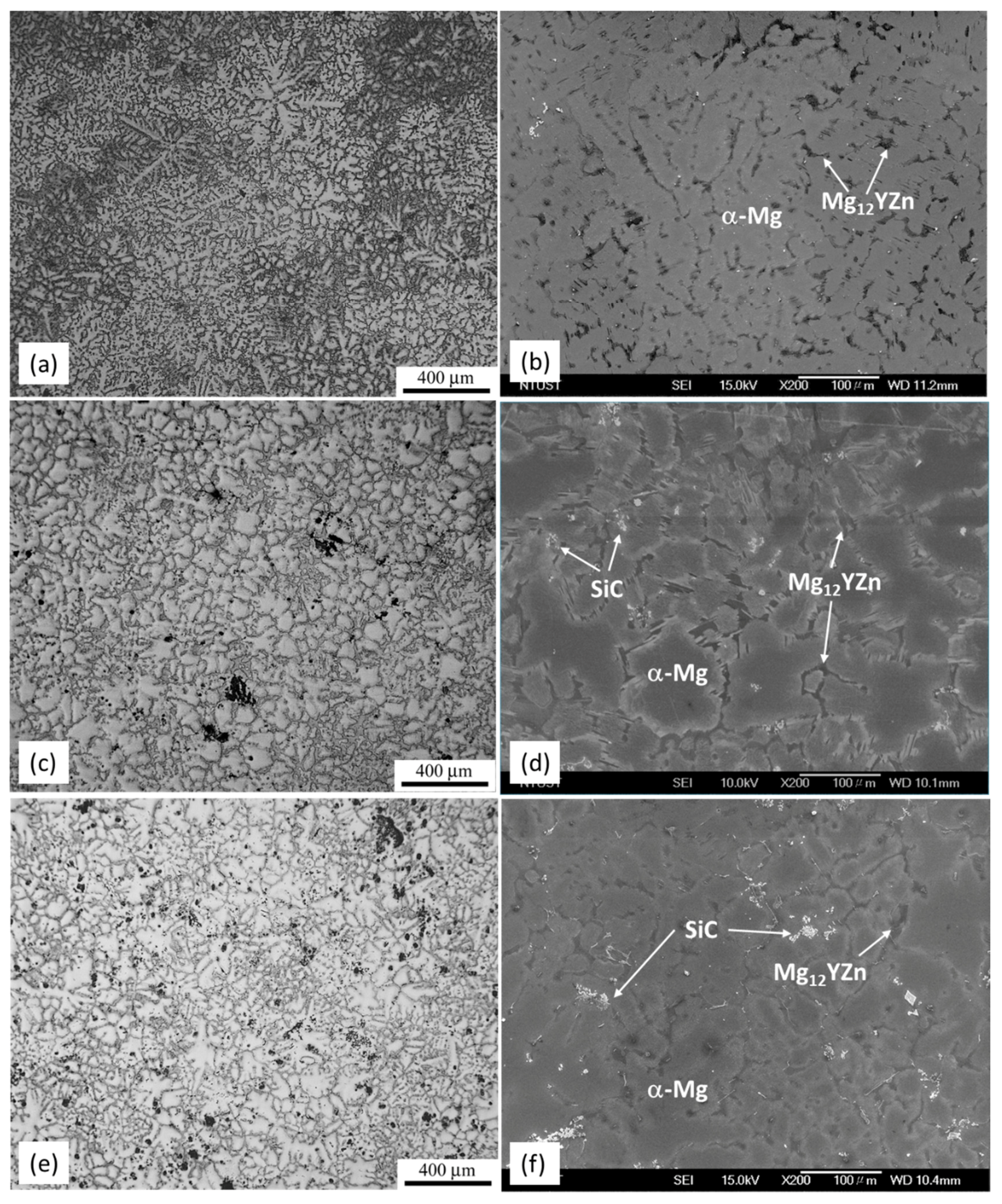
Figure 2.
Scanning Electron Microscope (SEM) micrographs showing the selected areas for Energy Dispersive Spectroscopy (EDS) analysis: (a) WZ73-1.5 vol % SiC; (b) WZ73-2.5 vol % SiC; (c) a SEM micrograph of the WZ73 alloy is also shown for comparison.
Figure 2.
Scanning Electron Microscope (SEM) micrographs showing the selected areas for Energy Dispersive Spectroscopy (EDS) analysis: (a) WZ73-1.5 vol % SiC; (b) WZ73-2.5 vol % SiC; (c) a SEM micrograph of the WZ73 alloy is also shown for comparison.
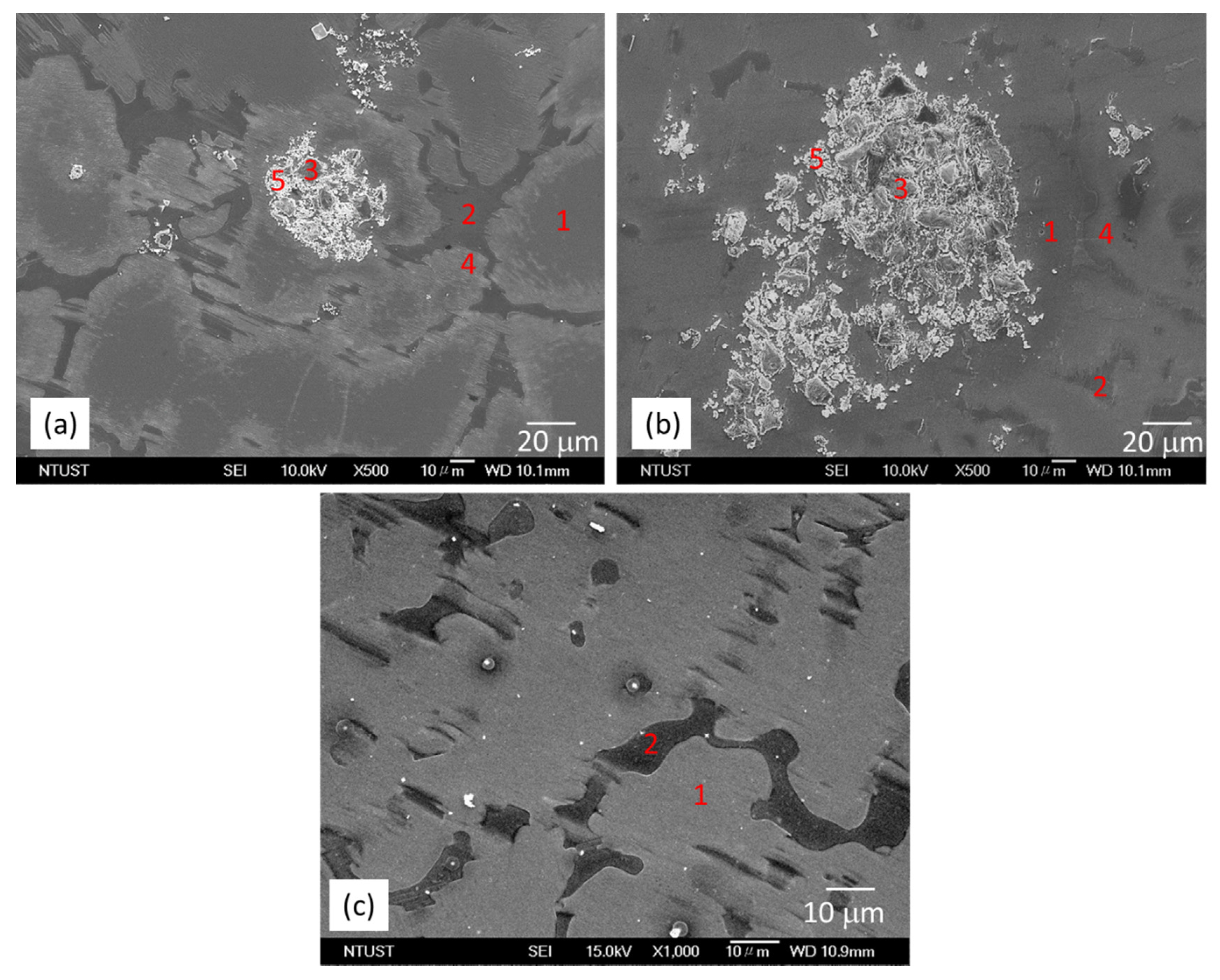
Figure 3.
X-ray Diffraction (XRD) patterns of WZ73 and MMCs: (a) WZ73; (b) WZ73-1.5 vol % SiC; (c) WZ73-2.5 vol % SiC and (d) Zoom in of the peaks of SiC and Mg12YZn in a 2 theta range of 35° to 39°.
Figure 3.
X-ray Diffraction (XRD) patterns of WZ73 and MMCs: (a) WZ73; (b) WZ73-1.5 vol % SiC; (c) WZ73-2.5 vol % SiC and (d) Zoom in of the peaks of SiC and Mg12YZn in a 2 theta range of 35° to 39°.

Figure 4.
Fracture morphologies of WZ73 and MMCs after tensile test: (a) WZ73; (b) WZ73-1.5 vol % SiC; and (c) WZ73-2.5 vol % SiC.
Figure 4.
Fracture morphologies of WZ73 and MMCs after tensile test: (a) WZ73; (b) WZ73-1.5 vol % SiC; and (c) WZ73-2.5 vol % SiC.
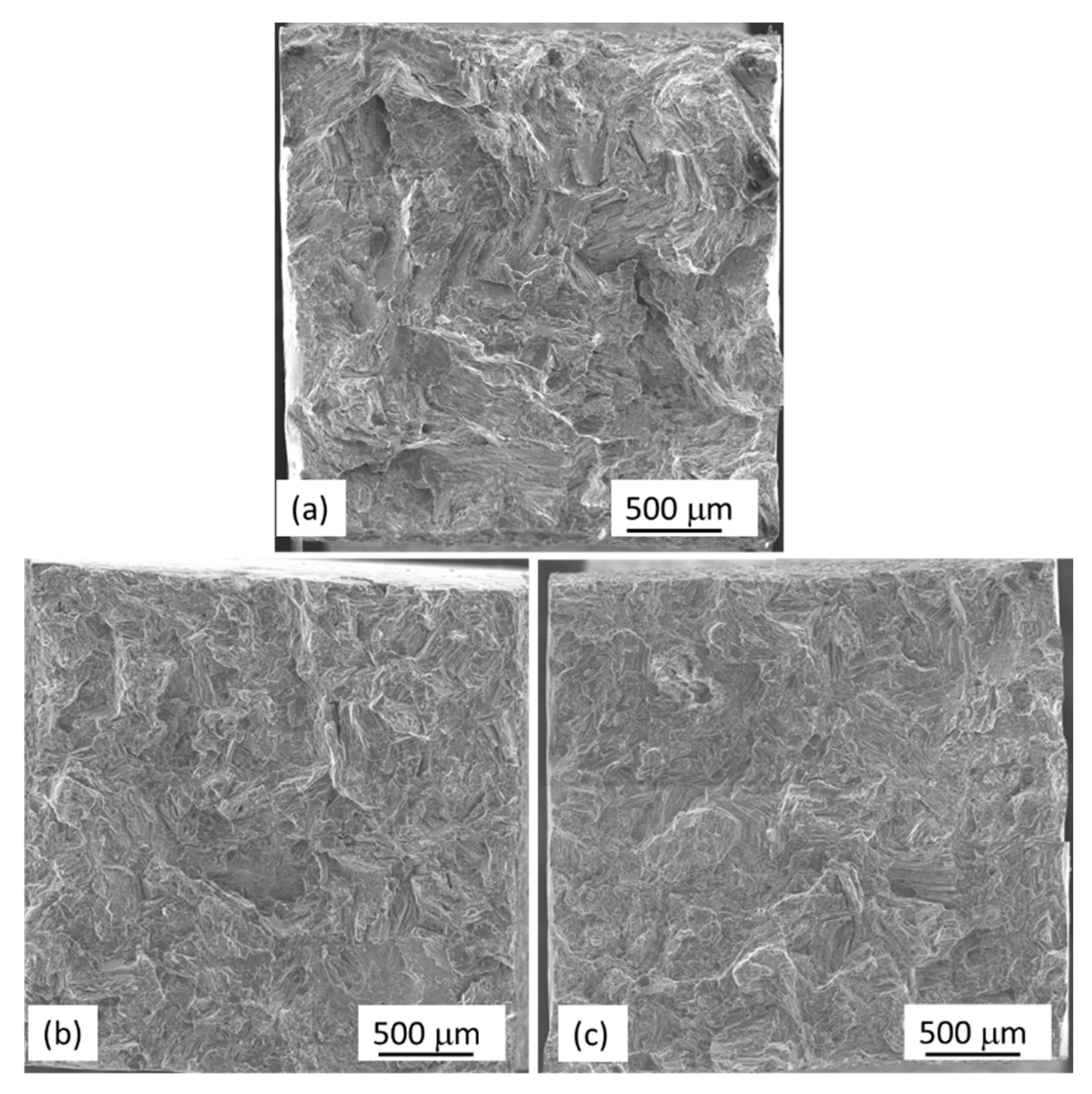
Figure 5.
Fracture morphologies under higher magnification showing clustering of SiC particles: (a) WZ73-1.5 vol % SiC and (b) WZ73-2.5 vol % SiC; (c) Optical microscope (OM) showing clustering of particles is favorite for crack formation.
Figure 5.
Fracture morphologies under higher magnification showing clustering of SiC particles: (a) WZ73-1.5 vol % SiC and (b) WZ73-2.5 vol % SiC; (c) Optical microscope (OM) showing clustering of particles is favorite for crack formation.
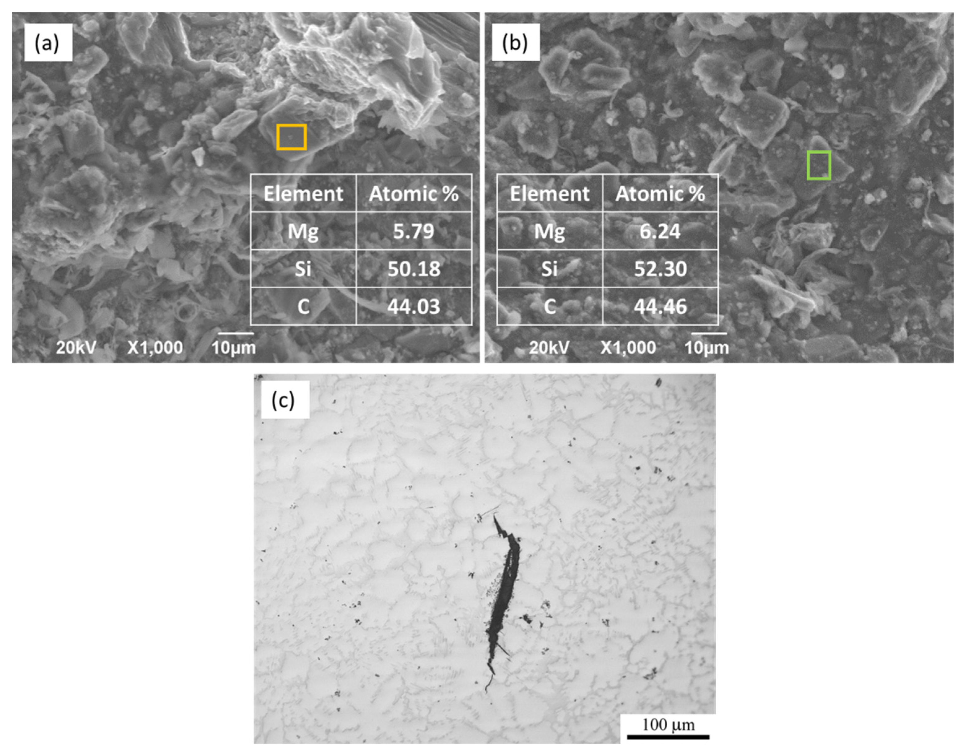
Figure 6.
Marco corrosion morphologies of the WZ73 alloy, WZ73-1.5 vol % SiC, and WZ73-2.5 vol % SiC composites immersed in 1 wt % NaCl solution for 1, 12 and 24 h.
Figure 6.
Marco corrosion morphologies of the WZ73 alloy, WZ73-1.5 vol % SiC, and WZ73-2.5 vol % SiC composites immersed in 1 wt % NaCl solution for 1, 12 and 24 h.
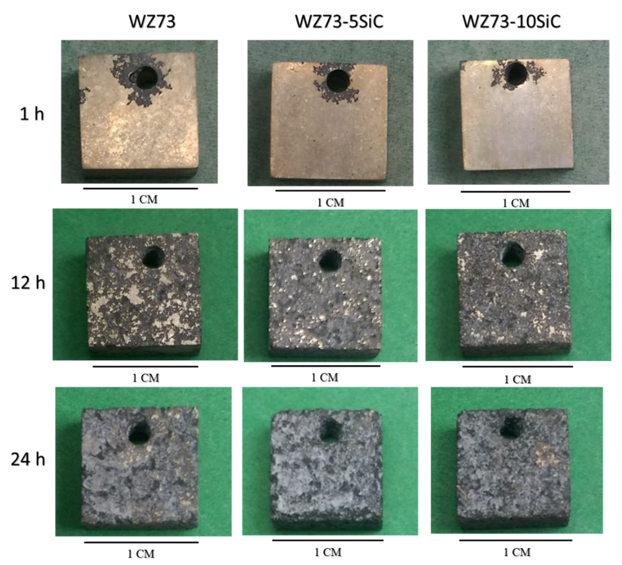
Figure 7.
Surface morphology of WZ73 after immersing in 1 wt % NaCl solution for (a) 1; (b) 12 and (c) 24 h; WZ73-1.5 vol % SiC after (d) 1; (e) 12 and (f) 24 h; WZ73-2.5 vol % SiC after (g) 1; (h) 12 and (i) 24 h.
Figure 7.
Surface morphology of WZ73 after immersing in 1 wt % NaCl solution for (a) 1; (b) 12 and (c) 24 h; WZ73-1.5 vol % SiC after (d) 1; (e) 12 and (f) 24 h; WZ73-2.5 vol % SiC after (g) 1; (h) 12 and (i) 24 h.

Figure 8.
XRD patterns of the surface corrosion layers in WZ73 and MMCs after immersing in 1 wt % NaCl solution for (a) 12 h and (b) 24 h.
Figure 8.
XRD patterns of the surface corrosion layers in WZ73 and MMCs after immersing in 1 wt % NaCl solution for (a) 12 h and (b) 24 h.
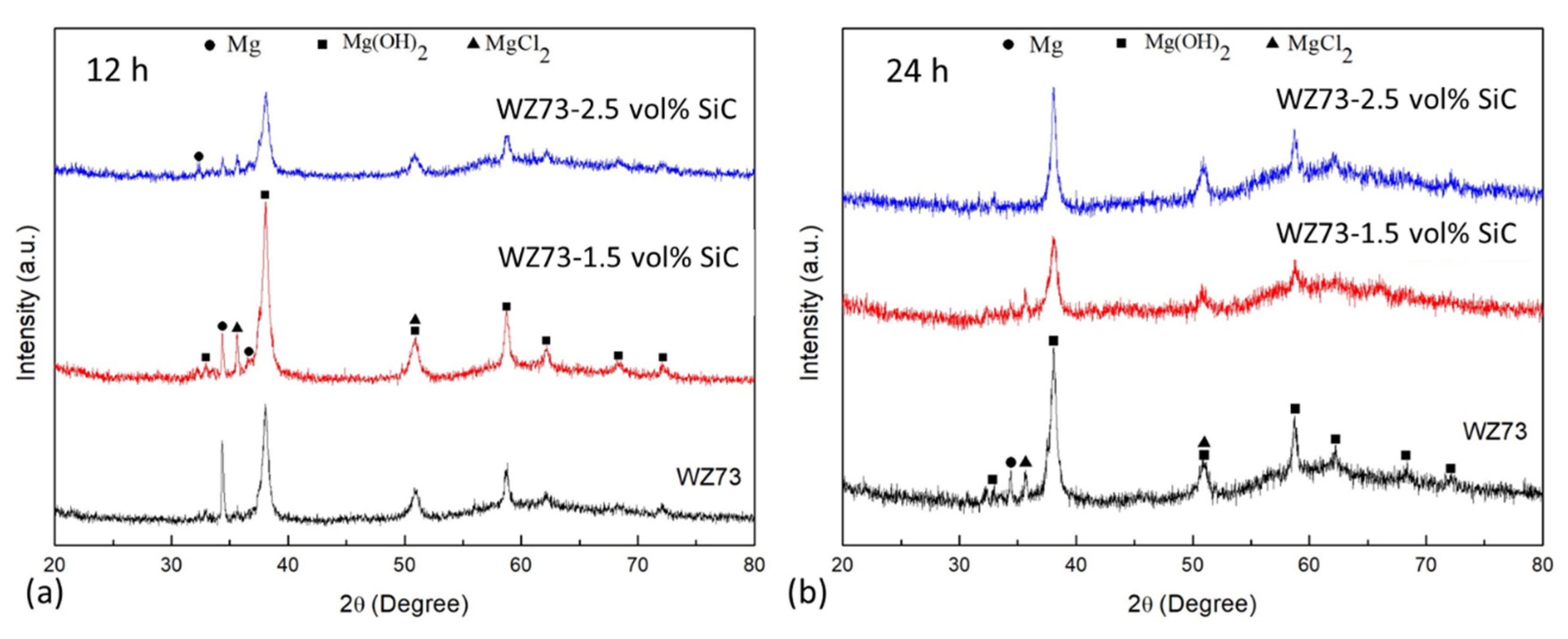
Figure 9.
Surface morphology of WZ73 and MMCs after removing corrosion products: (a) WZ73; (b) WZ73-1.5 vol % SiC and (c) WZ73-2.5 vol % SiC.
Figure 9.
Surface morphology of WZ73 and MMCs after removing corrosion products: (a) WZ73; (b) WZ73-1.5 vol % SiC and (c) WZ73-2.5 vol % SiC.
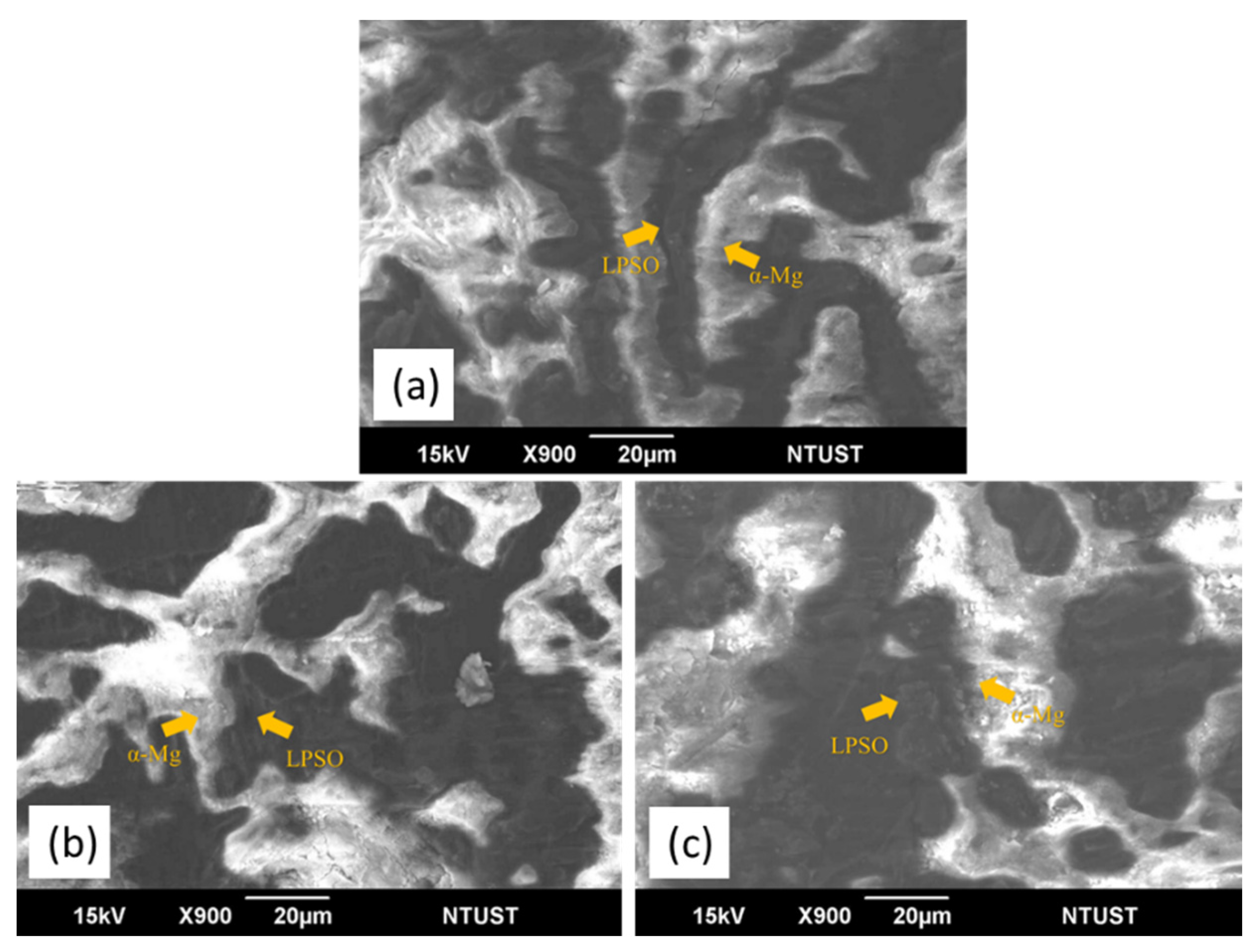
Figure 10.
Cross section of MMC after immersion test showing corrosion in the selected regions: (a) α-Mg matrix/LPSO region; (b) α-Mg matrix/SiC region.
Figure 10.
Cross section of MMC after immersion test showing corrosion in the selected regions: (a) α-Mg matrix/LPSO region; (b) α-Mg matrix/SiC region.
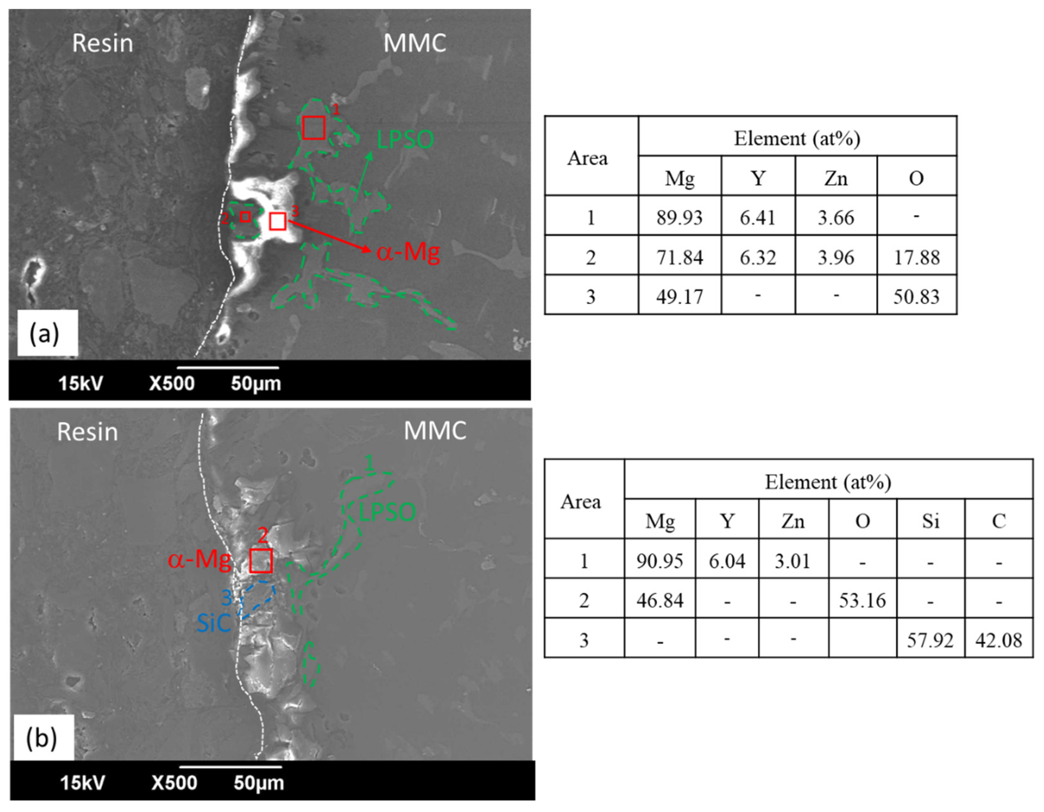
Figure 11.
Mass losses of WZ73, WZ73-1.5 vol % SiC, and WZ73-2.5 vol % SiC alloys as a function of immersion time in a 1 wt % NaCl solution.
Figure 11.
Mass losses of WZ73, WZ73-1.5 vol % SiC, and WZ73-2.5 vol % SiC alloys as a function of immersion time in a 1 wt % NaCl solution.


Table 1.
Chemical composition of selected areas in the WZ73 alloy and MMCs (at %).
| Sample | Zone | Element | |||||
|---|---|---|---|---|---|---|---|
| Mg | Y | Zn | Si | C | O | ||
| WZ73 | 1 | 98.2 | 1.2 | 0.7 | - | - | - |
| 2 | 89.1 | 6.4 | 4.6 | - | - | - | |
| WZ73-1.5 vol % SiC | 1 | 98.8 | 0.9 | 0.3 | - | - | - |
| 2 | 90.0 | 5.8 | 4.2 | - | - | - | |
| 3 | 1.4 | - | - | 47.8 | 50.8 | - | |
| 4 | 98.0 | 1.4 | 0.6 | - | - | - | |
| 5 | 48.5 | 22.4 | - | 18.7 | - | 10.4 | |
| WZ73-2.5 vol % SiC | 1 | 99.3 | 0.3 | 0.4 | - | - | - |
| 2 | 90.1 | 5.3 | 4.5 | ||||
| 3 | 1.1 | - | - | 42.4 | 56.5 | - | |
| 4 | 98.2 | 0.9 | 0.9 | - | - | - | |
| 5 | 36.3 | 25.9 | - | 23.8 | - | 14.0 | |
Table 2.
Volume fraction of phases, grain size, and tensile properties of the WZ73 alloy and MMCs.
| Sample | α-Mg (%) | LPSO (%) | Grain Size of α-Mg(µm) | YS (MPa) | UTS (MPa) | Elongation (%) |
|---|---|---|---|---|---|---|
| WZ73 | 77.2 | 22.8 | 143 | 126 ± 13 | 172 ± 9 | 9 ± 1 |
| WZ73-1.5 vol % SiC | 80.3 | 19.7 | 118 | 160± 1 | 223 ± 8 | 6 ± 2 |
| WZ73-2.5 vol % SiC | 84.1 | 15.9 | 114 | 154 ± 9 | 238 ± 9 | 7± 1 |
Table 3.
Vickers hardness (HV) of the selected areas in the tested alloys.
| Sample | α-Mg | α-Mg (Near Particles) | LPSO |
|---|---|---|---|
| WZ73 | 77 ± 3 | - | 115 ± 6 |
| WZ73-1.5 vol % SiC | 81 ± 9 | 86 ± 13 | 121 ± 5 |
| WZ73-2.5 vol % SiC | 79 ± 5 | 89 ± 8 | 119 ± 5 |
Table 4.
Corrosion rate of WZ73 and MMCs obtained from mass loss after immersing in a 1 wt % NaCl solution for 24 h.
Table 4.
Corrosion rate of WZ73 and MMCs obtained from mass loss after immersing in a 1 wt % NaCl solution for 24 h.
| Sample | Mass Loss (mg/cm2) | Corrosion Rate (mm/year) |
|---|---|---|
| WZ73 | 6.3 | 16 |
| WZ73-1.5 vol % SiC | 13.8 | 27 |
| WZ73-2.5 vol % SiC | 12.8 | 25 |
© 2018 by the authors. Licensee MDPI, Basel, Switzerland. This article is an open access article distributed under the terms and conditions of the Creative Commons Attribution (CC BY) license (http://creativecommons.org/licenses/by/4.0/).
Share and Cite
MDPI and ACS Style
Chiu, C.; Liu, H.-C. Mechanical Properties and Corrosion Behavior of WZ73 Mg Alloy/SiCp Composite Fabricated by Stir Casting Method. Metals 2018, 8, 424. https://doi.org/10.3390/met8060424
AMA Style
Chiu C, Liu H-C. Mechanical Properties and Corrosion Behavior of WZ73 Mg Alloy/SiCp Composite Fabricated by Stir Casting Method. Metals. 2018; 8(6):424. https://doi.org/10.3390/met8060424
Chicago/Turabian StyleChiu, Chun, and Hsu-Chieh Liu. 2018. "Mechanical Properties and Corrosion Behavior of WZ73 Mg Alloy/SiCp Composite Fabricated by Stir Casting Method" Metals 8, no. 6: 424. https://doi.org/10.3390/met8060424
Note that from the first issue of 2016, this journal uses article numbers instead of page numbers. See further details here.