Review

Strongly Orthotropic Open Cell Porous Metal Structures for Heat Transfer Applications

Department of Cellular Metallic Materials, Fraunhofer Institute for Manufacturing Technology and Advanced Materials, Winterbergstr. 28, D-01277 Dresden, Germany
*
Author to whom correspondence should be addressed.
Metals 2018, 8(7), 554; https://doi.org/10.3390/met8070554
Submission received: 20 May 2018 / Revised: 5 July 2018 / Accepted: 9 July 2018 / Published: 19 July 2018
(This article belongs to the Special Issue Porous Metals and Metallic Foams)

Abstract

:
For modern thermal applications, open cell porous metals provide interesting opportunities to increase performance. Several types of cellular metals show an anisotropic morphology. Thus, using different orientations of the structure can boost or destroy the performance in thermal applications. Examples of such cellular anisotropic structures are lotus-type structures, expanded sheet metal, and metal fiber structures. Lotus-type structures are made by casting and show unidirectional pores, whereas expanded sheet metal structures and metal fiber structures are made from loose semi-finished products that are joined by sintering and form a fully open porous structure. Depending on the type of structure and the manufacturing process, the value of the direction-dependent heat conductivity may differ by a factor of 2 to 25. The influence of the measurement direction is less pronounced for the pressure drop; here, the difference varies between a factor of 1.5 to 2.8, depending on the type of material and the flow velocity. Literature data as well as own measurement methods and results of these properties are presented and the reasons for this strongly anisotropic behavior are discussed. Examples of advantageous applications, for example a latent heat storage device and a heat exchanger, where the preferential orientations are exploited in order to gain the full capacity of the structure’s performance, are introduced.

1. Introduction

In the last two decades, porous metals were tested for mechanical and thermal applications. Especially open porous metals, like metal foam, lotus-type structures, and metal fiber structures attracted much interest for thermal applications [1,2,3,4,5]. Therefore, they were experimentally tested e.g., as heat exchanger material replacing conventional fins. Not for all applications, the anisotropy was taken into account appropriately. Especially, metal fiber structures in heat exchangers [6,7] could have been used in an optimized orientation. In general, the directional properties of anisotropic open porous metal structures provide advantageous heat conduction or pressure drop in a distinct direction, whereas they can be much worse in another direction. To challenge highly optimized conventional solutions for nowadays-thermal applications, like high power electronics, battery cooling, and sorption heat pumps, it is necessary to understand and respect the directional properties of heat conductivity and pressure drop.
The anisotropy of the heat conductivity of open porous materials, like sintered metal fiber structures [8] and lotus-type structures [9], was investigated by finite element simulations that are based on computer tomography data and compared with experimental data. The anisotropy shown is of an orthotropic kind. Orthotropy is a special case of anisotropy: along three mutually orthogonal axes or planes there is a symmetry when the structure is rotated by 180° around one of these axes.
In addition to short sintered metal fiber structures and lotus-type structures, the present paper also discusses the anisotropy of metal fiber structures built up from long directional fibers, and expanded sheet metal structures. To the best knowledge of the authors, the latter two have not been described in literature elsewhere.
It has to be noted that open porous metal sponges exhibit anisotropic properties as well [10,11]; however, the degree of anisotropy is quite small and simply an unwanted byproduct of the manufacturing process. Additionally, the inner structure does not reveal the anisotropy at first glance and deliberate modification during the fabrication process is difficult.
In this paper, we focus on structures with strong orthotropy. We start with lotus-type structures with well-defined pores and an exclusively one-directional open porosity, followed by sintered expanded sheet metal structures with geometrically defined openings in each layer and a fully open porosity, and lastly sintered metal fiber structures with a random pore morphology and a fully open porosity are presented. The first section introduces their respective manufacturing techniques as they determine the inner structure, and, thus the degree of orthotropy. Crucial properties for thermal applications, like pressure drop and heat conductivity, are discussed in the following section. The preferred measurement method is discussed first followed by the directional properties of each type of structure. At last, potential applications and applications that have reached a demonstration level will be reviewed and assessed.

2. Manufacturing Techniques

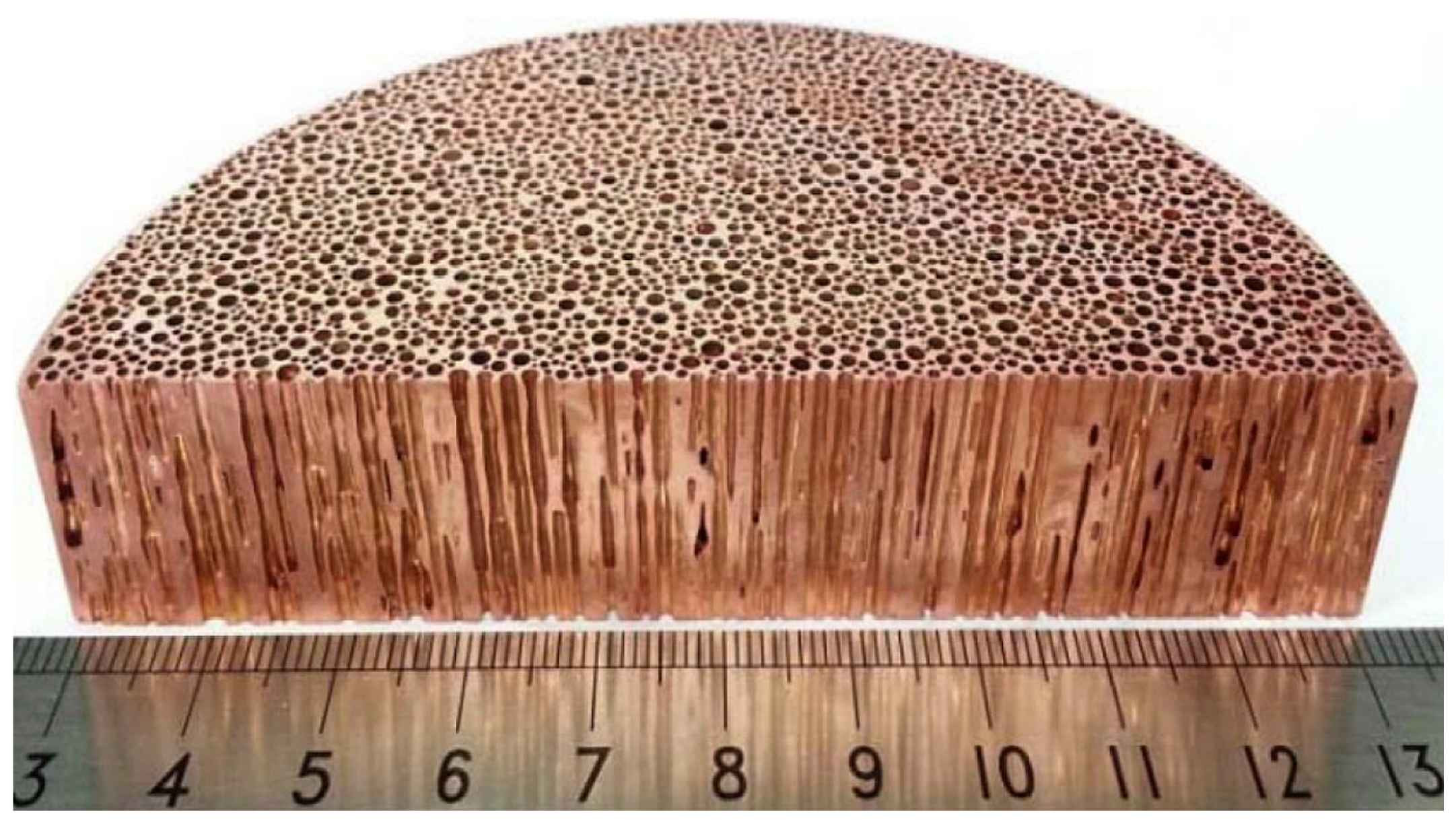
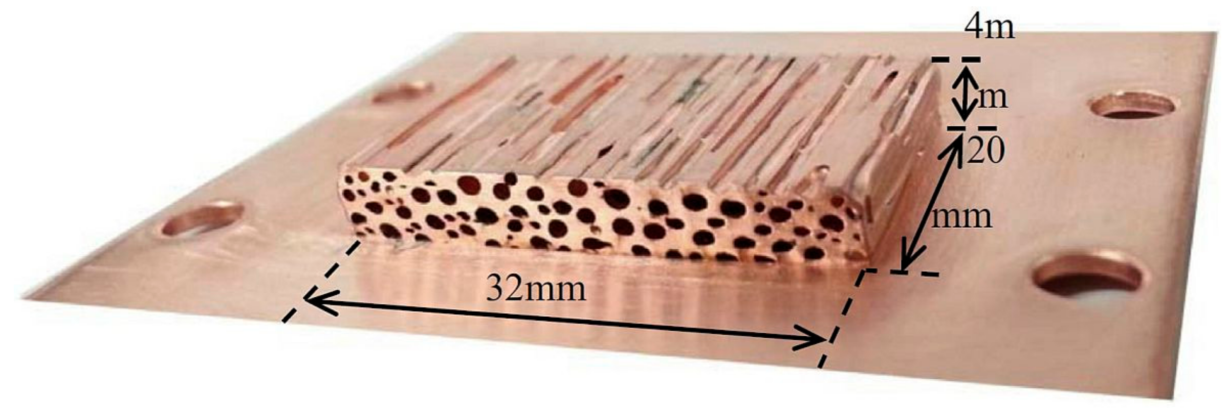
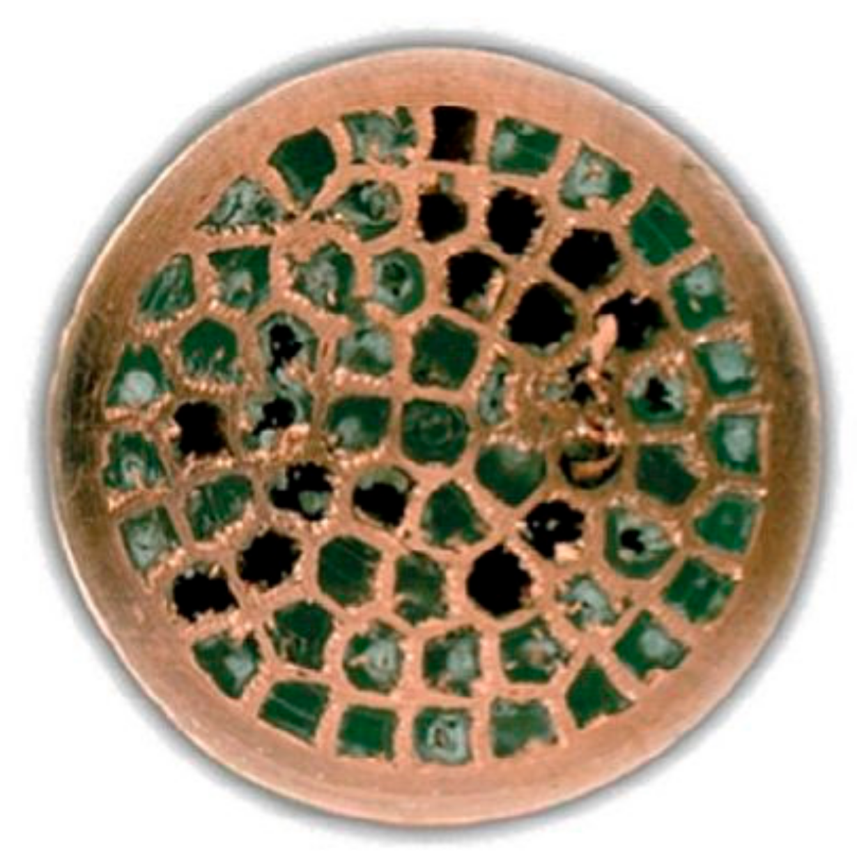
2.1. Manufacturing of Lotus-Type Structures

Lotus-type structures shows a strong structural orthotropy, which is caused by elongated unidirectional pores, like in a lotus root. Due to their aligned pores, they are a special case of open porous structures, with the openings only along one spatial direction. A section of a porous lotus-type copper ingot is shown in Figure 1. The lotus-type structure was first investigated as a metal sponge structure by Shapovalov et al. [12], earlier investigations only thought about the pores as a casting defect. Nakajima and its collaborators refined the production method and intensified their characterization [13,14,15,16]. Today, there are many different manufacturing methods for lotus-type structures, which can be split in major fabrication techniques. A brief description is given below and a detailed description can be found in [15,17].
The “high-pressurized gas method” (PGM) makes use of unidirectional solidification and the solubility gap between a melt and its solid. A highly pressurized chamber with hydrogen or nitrogen gas leads to a high amount of dissolved gas in the molten metal. When the melt solidifies, due to local cooling the solubility of the gas is lowered abruptly, leading to the formation of gas bubbles. The elongation and alignment of the gas bubbles is enforced by unidirectional solidification. Local heating and cooling can assist in the unidirectional solidification, and therefore the elongation of the finally formed pores.
A more industrial approach is the formation of gas in the molten metal by the decomposition of a metal compound, like calcium nitride or titanium hydride. The “thermal decomposition method” (TDM) leads to pores similar to the aforementioned method of PGM.
Lotus-type materials can be made from iron, nickel, aluminum, copper, magnesium, cobalt, tungsten, manganese, chromium, beryllium, and their alloys [15,18], but not all fabrication techniques can be applied for each material. Depending on the gas, the gas pressure or the amount of metal compound, a maximum porosity of approximately 55% can be reached [15,17]. The pore diameter is a consequence of the solidification velocity. Mean pore diameters of 50 µm at 23% porosity up to several millimeters mean pore diameter at higher porosities were reached [19].
A recent approach starting with semi-finished products for lotus-type or so called UniPore structures was shown by Fiedler et al. [1] and Hokamoto et al. [20]. Based on explosive compaction of a copper or an aluminum pipe filled with smaller pipes of the same material, an open porous structure with elongated unidirectional pores can be obtained. The high pressure achieved by the detonation leads to compaction of the outer pipe and welding between the outer and inner pipes’ surfaces.
Another approach to bond pipes is to dip them into a melt or a semi-solid base metal [21]. In contrast to UniPore structures, the resulting pores are still perfectly cylindrical.
Lotus-type structures (including UniPore) show a more or less random distribution of pores perpendicular to the direction of the pore elongation (Figure 1). Consequently, all material properties radial to this direction should be isotropic. Only a rotation by 180° around a perpendicular axis to the direction of the pore elongation will result in the same properties. This so-called transverse isotropy can be considered as a special case of orthotropy because of the typical 180° symmetries of the three axes in orthotropic systems.

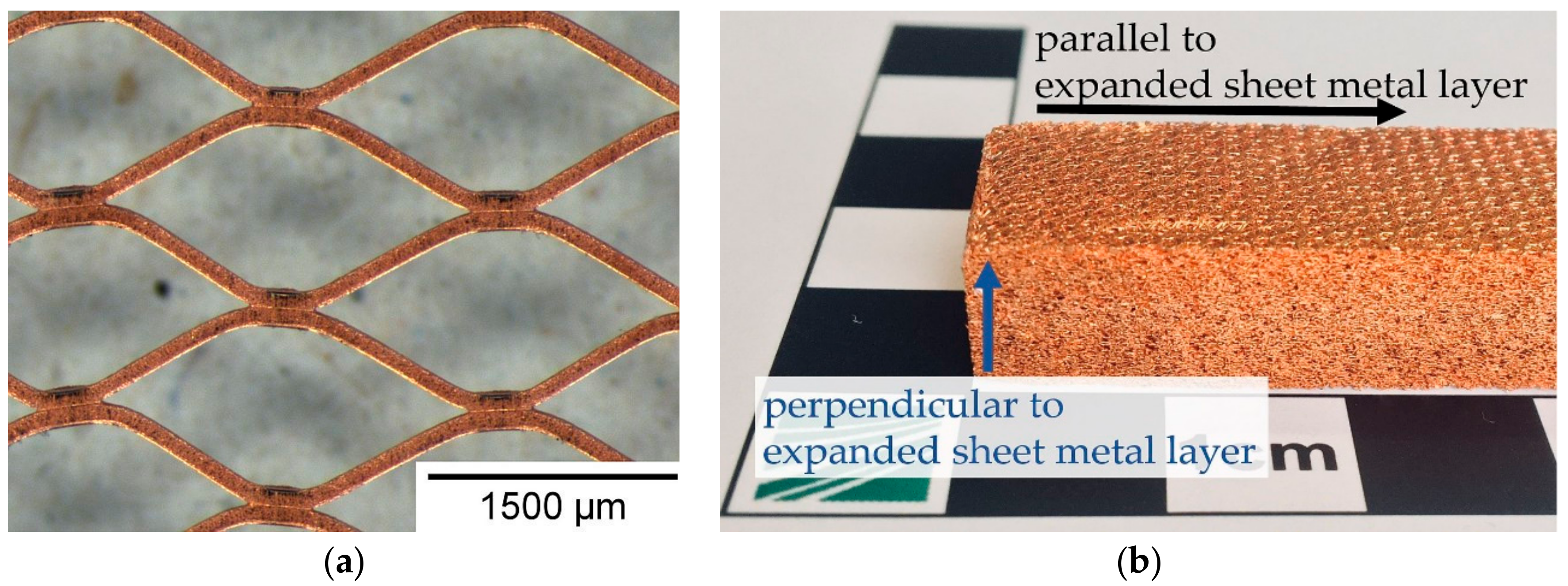
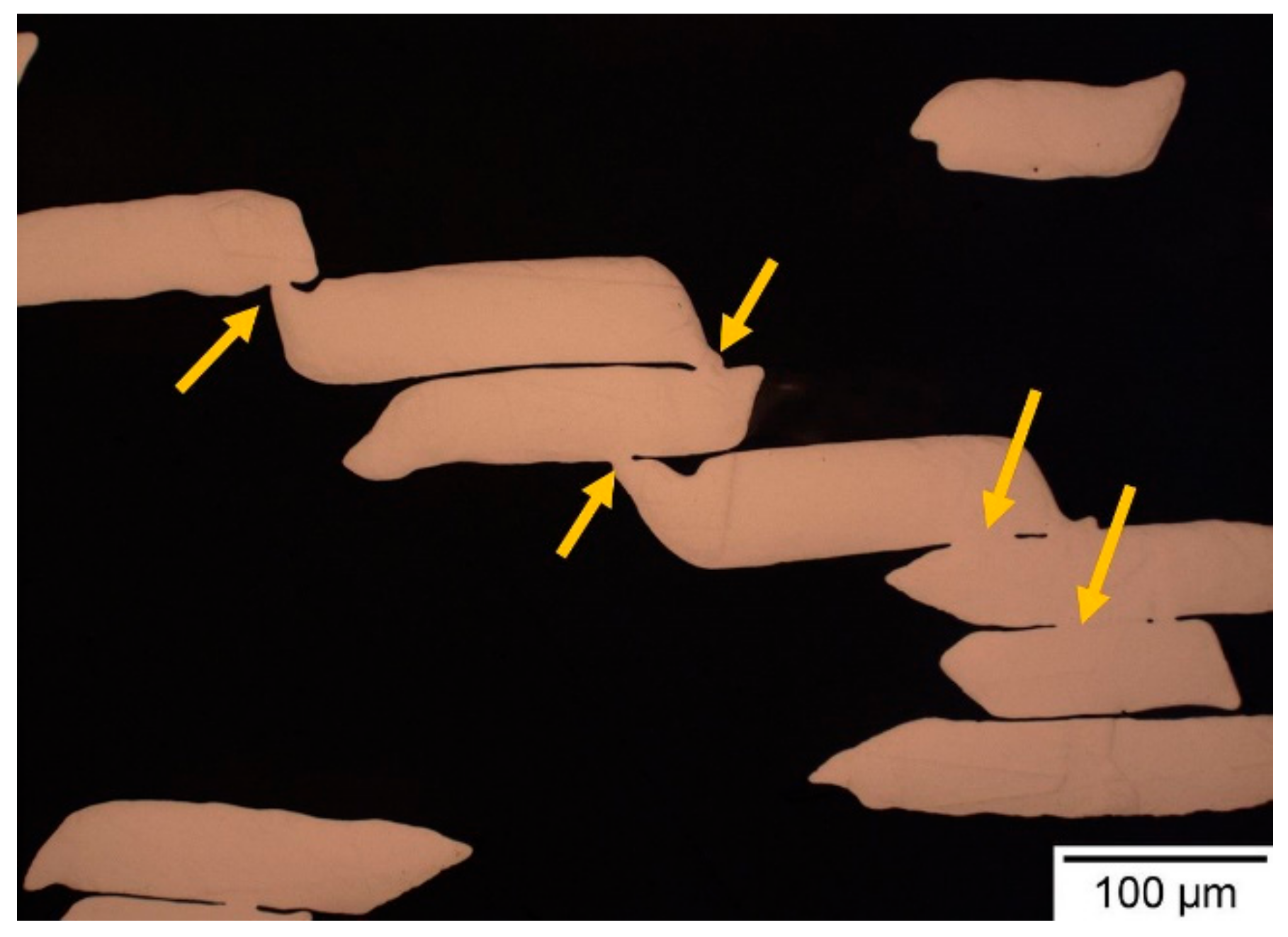
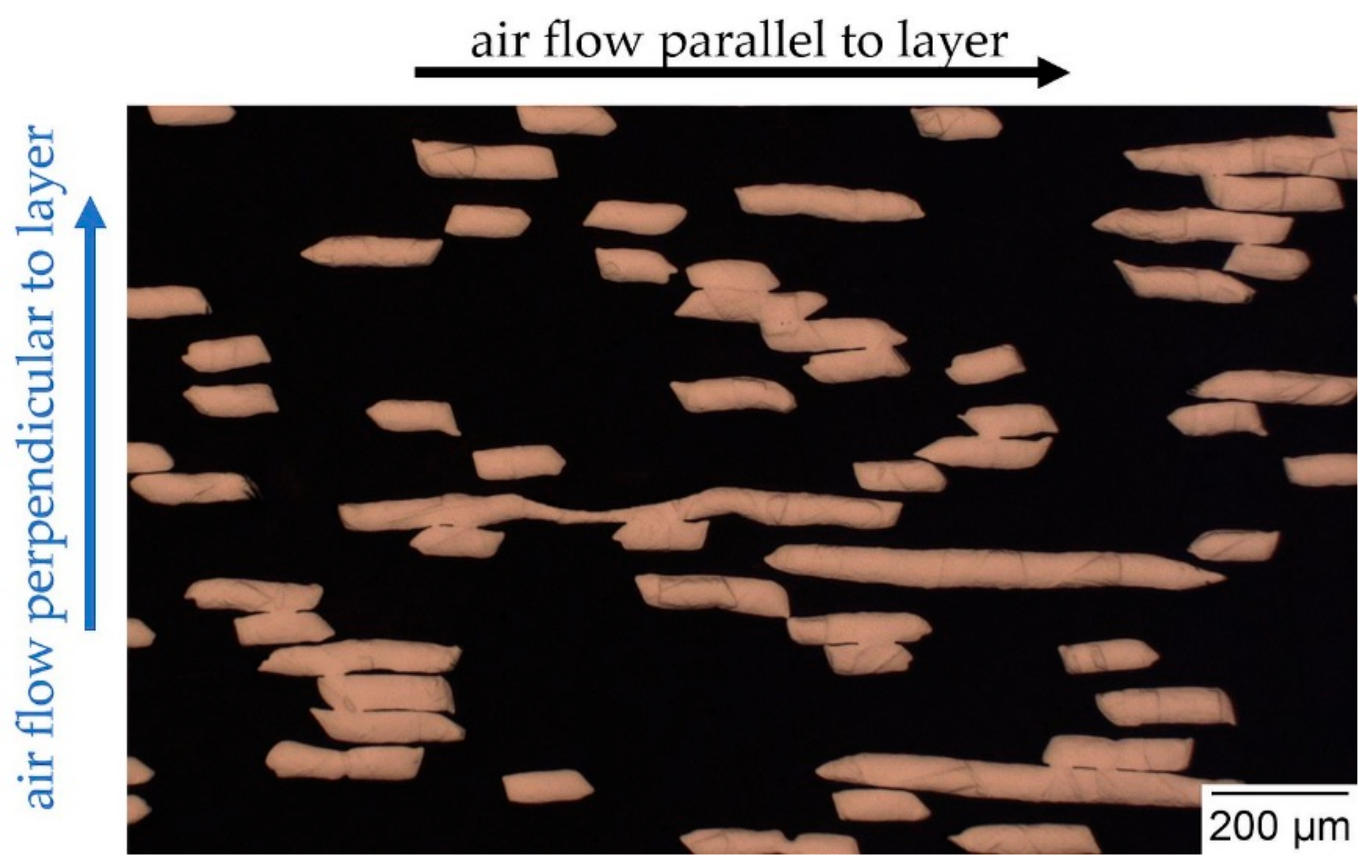
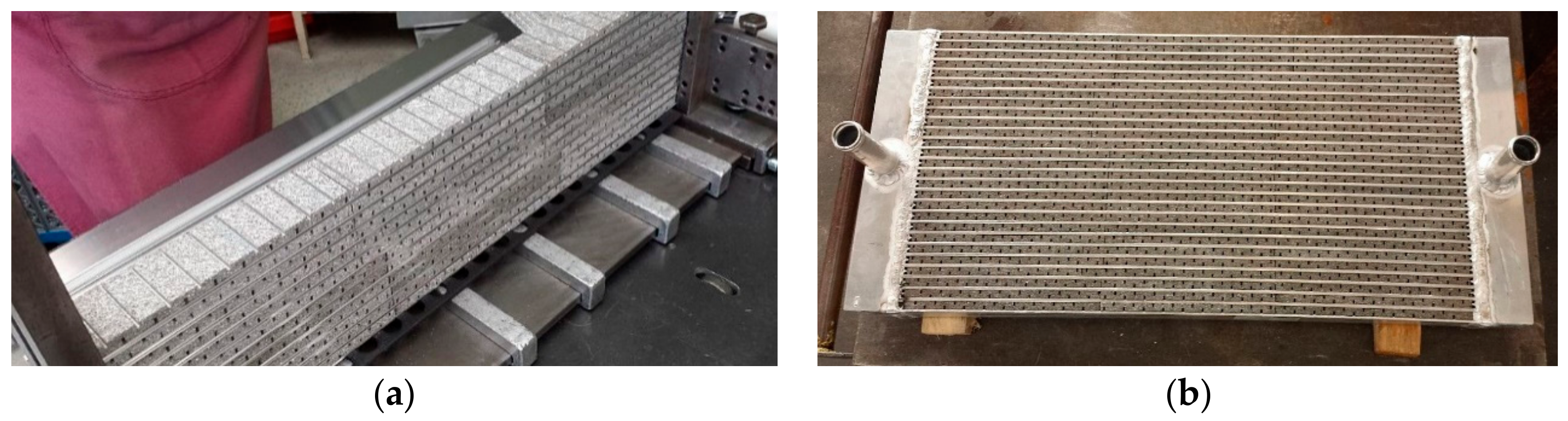
2.2. Manufacturing of Sintered Expanded Sheet Metal Structures

Expanded sheet metal structures, like in Figure 2, consist of several tens to hundreds of single expanded metal sheet layers that are bonded to each other by sintering. Recently, structures made from pure copper with 200 to 250 layers were investigated for thermal applications. Expanded metal sheet is manufactured by a process of slitting and stretching of a metal foil. Fabrication of thin copper foils is accomplished by electrodeposition on a rotating drum to reach a foil thickness of 50 µm. In a single operation, a precision die slits and stretches the material. A set of rollers adjusts the final thickness. Different tools generate different shapes, forms, and numbers of openings. For an expanded sheet metal structure, an expanded metal sheet, as shown in Figure 2, was used having an open area of 75% to 80% and narrow struts with a cross section of 50 µm by 100 µm. A single mesh has diamond shaped openings with 1.2 mm short width and 2.5 mm long width of the diamond. Several hundred single layers of expanded metal sheets were stacked. During the stacking process, each layer was rotated by 90° around the normal vector of the expanded metal sheet in order to avoid a complete overlap of single sheets. A heat treatment under hydrogen atmosphere at 900 °C for 3 h leads to sinter bonds between the single layers. An additional weight on top of the stacked layers can be applied to adjust the total height of the structure, and, thus its final porosity.
As can be seen in Figure 3, small sinter necks form between individual expanded sheet metal layers. These can be many times smaller than the individual web widths of the expanded metal sheet, but it can also form over almost the entire surface of the strut. More detailed investigations on the formation of the sinter neck size, e.g., with µCT, are still pending and require a high resolution, since the expanded sheet metal layers are sometimes only a few micrometers apart but are still not in contact with each other.
The total porosity of sintered expanded sheet metal structures ranged from 76% to 87%. By using smaller meshes, thicker struts, and smaller open areas, lower porosities can be achieved. Expanded metal sheets with open areas larger than 80% are available and could lead to structures with 90% total porosity.
A single sheet of expanded metal is orthotropic. The arrangement of the expanded sheet metal layers (rotation of each layer by 90°) creates a new symmetry along the normal vector of the expanded metal sheet. Every 90° rotation of the structure around the normal vector leads to the same properties again. Consequently, the structure shows a rotational symmetry of 180° for the spatial axes along the expanded sheet metal layer. Thus, an expanded sheet metal structure shows a special form of orthotropy.

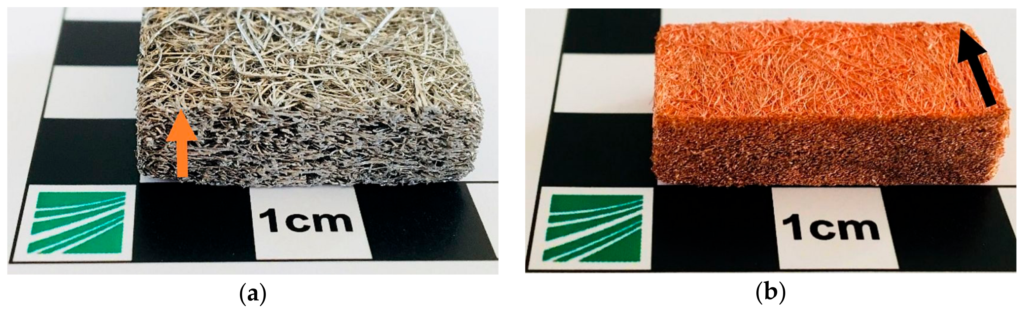
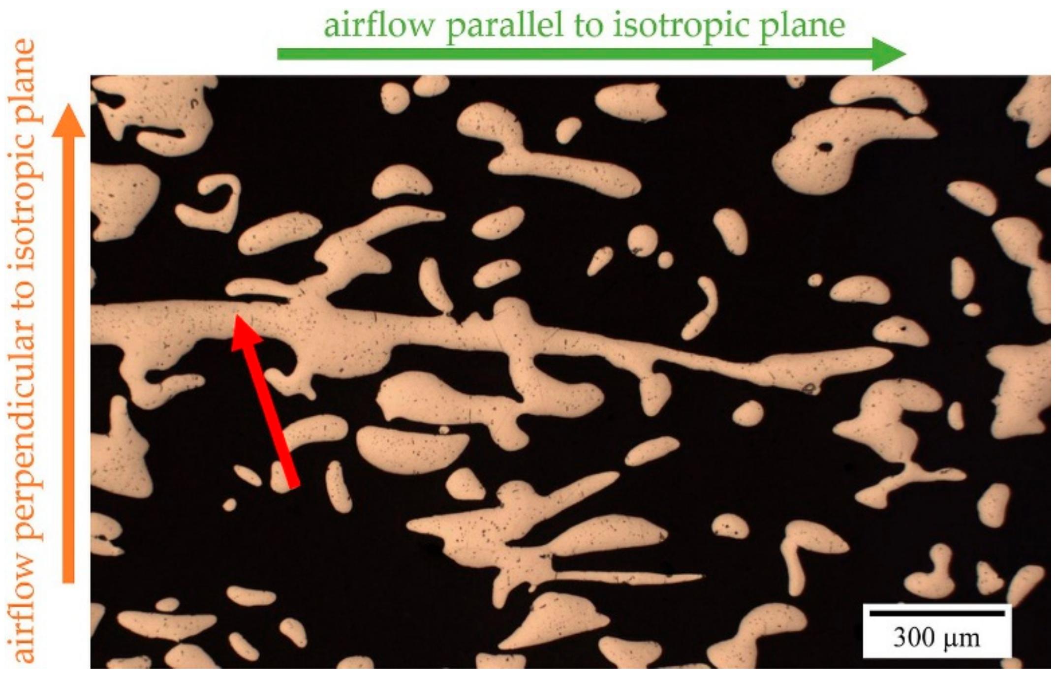
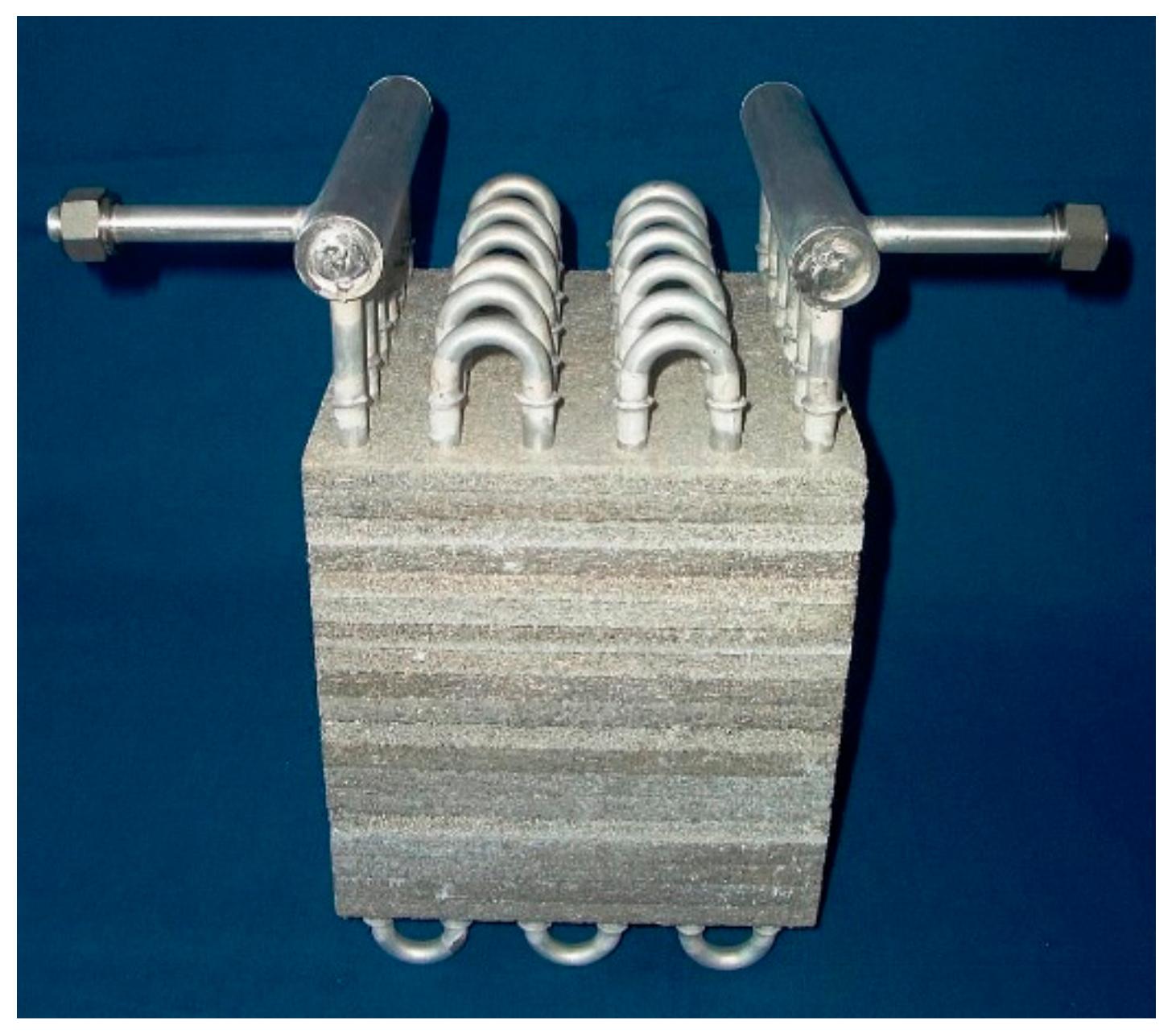
2.3. Manufacturing of Sintered Metal Fiber Structures

Open porous metal fiber structures are made from single metal fibers. Two examples of such structures are shown in Figure 4. With the help of a heat treatment, the fibers are bonded to each other e.g., due to sintering or liquid-phase sintering. The metal fibers can consist of a variety of metals and alloys, including common metals, like aluminum, copper, and stainless steel for thermal applications.
Aluminum short-fiber structures have been made by liquid-phase sintering, using short metal fibers made of AlZnCu [22], AlCu5, or most recently AlSi1 [6]. Crucible melt extraction (CME) has been applied for the production of such fibers. A rotating copper wheel with circumferential edges and a notched surface is placed over a melt pool. Wetting of the melt on the copper wheel edges leads to extraction of small amounts of melt, which immediately solidifies on the wheel and detaches from it due to shrinkage during solidification. The rotation of the copper wheel is fast enough for the production of kilograms of fibers per hour. The as-formed fibers typically show a sickle or kidney shaped cross-section with mean equivalent circle diameters in the range of 50 µm to 250 µm and a length of 5 mm to 15 mm.
The fibers are homogeneously deposited on a substrate (graphite in case of aluminum) by the rotating sieve drum technology [22]. During sintering, the fiber deposit is compressed in a controlled manner by the weight of another substrate placed on top of the deposit, resulting in a preset height, and therefore a defined total porosity of the structure.
Copper fiber structures can be made of short fibers, too, but much better is the application of long or endless curly fibers. Shaving from wire offers the opportunity of producing semi-endless fibers. In commercial processes, the wire is drawn through a special multi-blade cutting tool, which yields a high productivity. The fibers are bundled in a strand and collected on reels. Strands of finite length can be cut from the reel and stacked, with the fibers being mostly aligned in one direction. This way, structures are obtained that exhibit a very strong directional dependency of the thermal and flow properties. Due to a certain degree of curliness of the fibers, several contacts between fibers exist to still form a rigid structure in the sintering process and keep the structure fully permeable in all directions.
Fibers from the shaving process usually show a mean circle equivalent diameter of 60 µm to 120 µm. Both kinds of metal fiber structures can be made with porosities that are in the range of 60% to 90%. Thus, depending on the actual mean circle equivalent diameter, a specific surface area of 1600 m2/m3 to 26,000 m2/m3 can be obtained, depending on fiber diameter, fiber cross section, and total porosity of the structure. For example, the metal fiber structures shown in Figure 4 provide a specific surface area of 4600 m2/m3 and 7300 m2/m3, respectively, having the same porosity but different fiber diameters and cross sectional shapes.
Other types of porous metal fiber structures were made from bundle-drawn fibers [23] or via experimental manufacturing techniques, like the “cutting method” [24]. However, the chosen aluminum short-fiber structure and the copper long-fiber structure are representative of all of these types of metal fiber structures, therefore we will limit our discussion to the aforementioned fiber structures.
Figure 4 also shows the differences of the inner structure of both types of metal fiber structures. The top surface shows complete fibers whereas the front faces (cut by wire cutting) show small tiny dots (cut fiber cross sections) and in case of the short-fiber structure (Figure 4a) some longitudinally cut fibers. Technically speaking, these structures are a special case of orthotropy, like lotus-type structures. The typical isotropic plane of the transverse isotropy is marked in Figure 4 by an arrow representing its normal vector. Isotropic planes are generated by the way the fibers are deposited during manufacturing. When falling out of the sieve drum, the short metal fibers tend to lie parallel to the surface of the sintering substrate with arbitrary in-plane orientation, this way creating an isotropic plane. In contrast, long-fiber structures that are built from aligned fiber strands have a predominant orientation in the direction of the fiber alignment and an isotropic plane perpendicular to it.

3. Heat Conductivity

The heat conductivity of the fiber and expanded sheet metal structures was determined by own measurements, whereas the values for lotus-type structures were taken from literature. There exist several methods to measure the heat conductivity. For anisotropic open porous materials, a steady-state method should be applied [15]. Several different measurement setups exist that differ in detail, but they can suffer from different systematical errors. The measurement setup for the heat conductivity of expanded sheet metal and metal fiber structures is explained below. The errors that can occur in this setup are discussed and how to avoid it. Measurements that do not take these errors into account can lead to inaccurate measurement values for the thermal conductivity of porous structures.

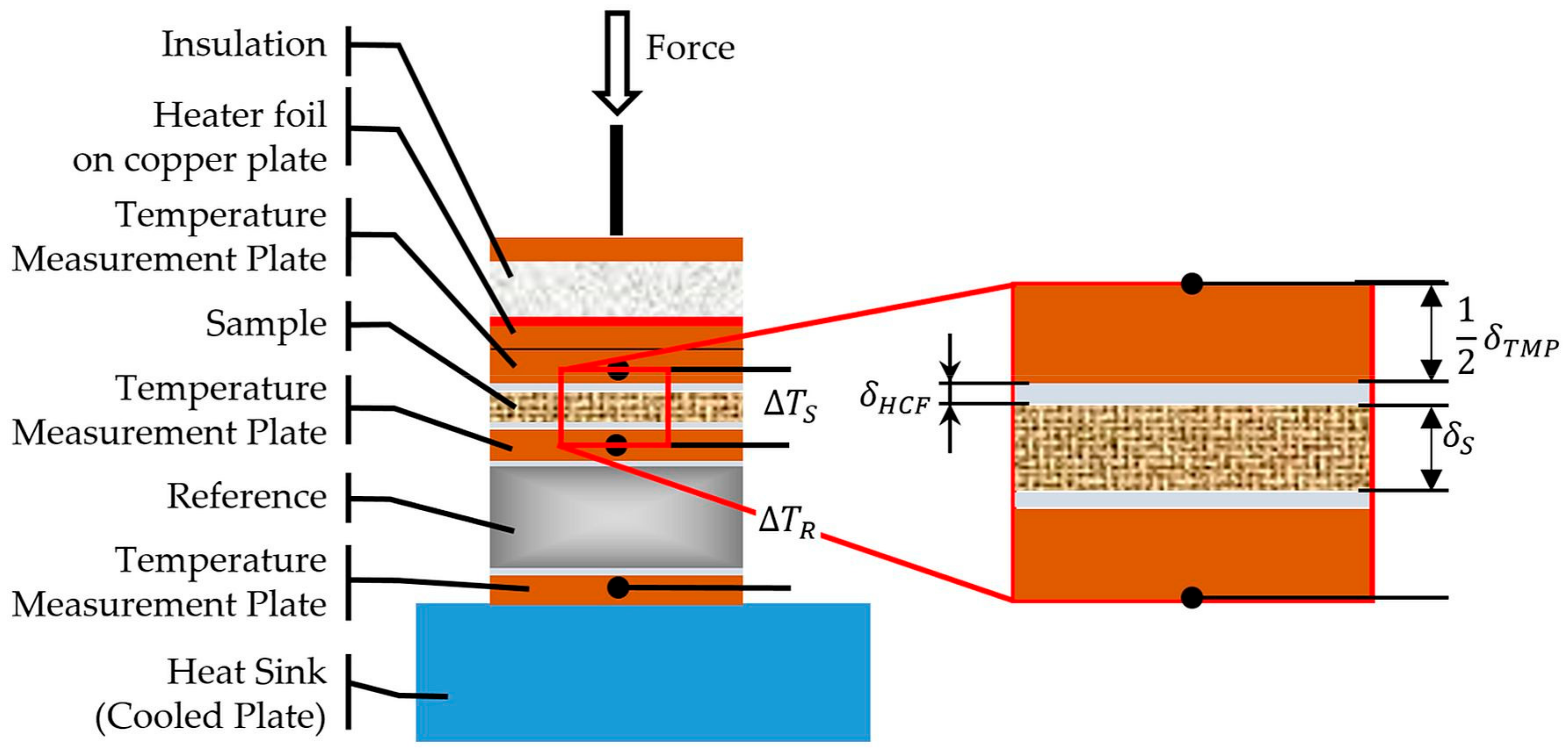
3.1. Measurement Setup

The stationary plate method used here determines the thermal conductivity of open porous material in accordance with DIN EN 12664 [25]. Similar constructions are described for other sample thicknesses and higher thermal conductivities in the related standards [26,27]. The method makes use of Fourier’s Law:
q ˙ ^ = Q ˙ A = λ   d ϑ d x ,
where Q ˙ represents the heat flux, A the cross-sectional surface area, d ϑ / d x describes the temperature difference related to the thickness of the sample, and λ is the heat conductivity of the material. The apparatus does not determine the heat flux density from a direct measurement, as described in [25,26,27]. Instead, a reference sample with a known heat conductivity and thickness is used. By measuring the temperature difference of both surfaces of the reference sample, the heat flux can be calculated with the help of Equation (1).
The applied layer composition for the measurement stack is shown schematically in Figure 5. The surface area of the stack measures 30 mm × 30 mm. The stack consists of several temperature measurement plates (TMP) that are made of copper, the reference sample (grey), and the test specimen. Heat conductive foils (HCF) are used as interface material between TMP, reference, and specimen to minimize contact resistances. The red line above the top measurement plate represents a heater foil as the heat source, and the blue area at the bottom is a cooling plate connected to a chiller acting as a heat sink. The whole stack is thermally insulated and at the top of the stack, a defined pressure can be applied for taking the compressibility of the samples into account, ensuring good contact between the different layers.
Within the TMP, three temperatures are measured using type K thermocouples. The heat flux through the measurement stack under steady-state conditions is constant in every layer (neglecting heat transfer to the surroundings). Therefore, the temperature differences over the reference sample Δ T R and the test specimen Δ T S are related to the corresponding thermal resistances R t h , R and R t h , S , respectively. Equation (1) transforms into
Q ˙ = Δ T S R t h , S = Δ T R R t h , R = const .
The temperature drop across a single layer corresponds to its thickness δ, surface area A, and thermal conductivity λ.
All of the layers between heater and cooling plate are considered as a series of thermal resistances with a constant surface A. The measured temperature difference across the sample includes also the thermal resistance of the heat conductive foils (HCF) as well as the half thickness of a temperature measurement plate (TMP). Therefore, Equation (2) can be written, as follows:
Q ˙ A = Δ T S δ S λ S + 2 ( δ H C F λ C H F + δ T M P 2 λ T M P ) = Δ T R δ R λ R + 2 ( δ H C F λ C H F + δ T M P 2 λ T M P )  
The index S represents the test specimen and the index R indicates the reference sample.
Equation (3) does not consider the contact resistances between the different layers because they cannot be determined in the context of this measurement stack, and therefore are unknown. If the contact resistances between sample and temperature measurement planes and between reference and temperature measurement planes are equal, they can be neglected in the evaluation. Particular attention must be paid to this when carrying out the measurement. The heat conducting foils between the different layers are used to compensate for possible unevenness and to achieve good thermal contact and thus minimize contact resistance. However, it is much more important that reproducible contact resistances are provided by these heat conducting foils and that the surfaces of the sample and the reference have a similar quality. This is especially difficult for the surface of porous materials that are consisting of tiny struts. This surface is rough when compared to a usual reference plate made from massive steel or glass. Schlott et al. [28] used the measurement setup at Fraunhofer IFAM Dresden. By using differently prepared aluminum short-fiber structure samples (as-cut from wire cutting and cut and polished samples), they showed that the measured heat conductivity can differ by 10% due to the different surface preparation. The contact influence can increase if the porous structure is connected to solid face sheets. The connection can be made by sintering, welding, or brazing, and it has an influence of up to 50% on the measured heat conductivity. Consequently, a comparison between different structures and even between similar structures with different types of face sheets needs to consider this potential error. For example, structures of the same porosity and comparable strut size may be compared to one another, or structures with connected face sheets of the same making can be compared to one another. However, a cross comparison of these different types of samples is not advisable. Therefore, for the evaluation of a structure for a certain application, it is best to join or bond the structure to sheets of the same material with the same joining technique as will be used in the real application.
As mentioned before, heat transfer to the surroundings is considered adiabatic. In the test setup, this is approximated with the aid of insulation. Studies show that the type of insulation plays a negligible role. Thus, polystyrene balls can be used as well as cut sheets of polystyrene or other materials. Additionally, the temperatures of the heat source and sink are selected such that the mean temperature of the stack measured between test specimen and reference corresponds to the ambient temperature.
Depending on the height of the stack, layers have a slightly higher or lower temperature than the surroundings, and therefore heat flow from the stack into the insulation (stack temperature higher than ambient temperature) or from the insulation into the stack (stack temperature lower than ambient temperature) occurs. Both of the heat flows are very difficult to determine, but it can also be neglected in the evaluation if they are of equal magnitude. This equality can be achieved if the temperature differences across the test specimen and the reference are equal. This also means that the temperature difference in relation to the environment is the same. If the thickness of the sample and the reference are also the same, the outgoing and the incoming heat flow are balanced and both can be neglected in the evaluation. These conditions lead to the necessity of the thermal resistance of the reference sample being very close to the expected thermal resistance of the test specimen. This means that a sufficiently large number of reference materials must be available in different thicknesses in order to determine the thermal conductivity with the aid of the stationary plate apparatus.
In addition, the maximum and minimum temperatures in the stack should not deviate too much from the mean, and thus from room temperature. At the same time, however, the temperature differences across sample and reference must not be too small and have to be adapted to the accuracy of the temperature sensors used in order to achieve reasonably accurate results. For type K thermocouples, a temperature difference of 10 K across the sample and reference was found to be a reasonable value.
These problems also exist when using a heat flow measuring plate, as described in [25]. Especially when measuring poorly conductive materials, a large temperature difference is generated across the sample depending on the imposed heat flow, which leads to heat flows from or to the environment. These heat losses are quantified by measuring the heat flux both at the heat source and the heat sink [29].

3.2. Heat Conductivity of Lotus-Type Structures

Due to the transverse isotropy of the structure, the heat conductivity is isotropic perpendicular to the pores [9] and it assumes its maximum parallel to the elongation of the pores. Ogushi et al. [30] carried out heat conductivity measurements on lotus-type copper. Different porosities and pore sizes were tested. The heat conductivity was measured by a steady-state method comparable, but not identical, to the aforementioned experimental setup. Experimental results are reproduced in Figure 6. It was found that in the direction parallel to the pores, the heat conductivity λ I I of the lotus-type structure depends linearly on the porosity Φ :
λ I I = ( 1 Φ ) λ s
with λs = 335 W/(m K) being the heat conductivity of the base material.
For the heat conductivity perpendicular to the elongation of the pores λ , Ogushi et al., state the following relation:
λ = λ s 1 Φ 1 + Φ ,
derived from Behrens’ [31] analytical investigation of the effective thermal conductivity of composite materials. The comparison of experimental data and analytical model showed good agreement.
The analytical behavior seems to be reasonable since, in the parallel direction, the elongated pores are no obstacles for the heat flow and only reduce the effective heat conducting cross section. In perpendicular direction, pores act as obstacles for the heat flow, forcing the heat flow to meander around the pores. Thus, the heat conductivity deviates from linearity.
According to the analytical models, the factor between the heat conductivities in the two directions is ( 1 + Φ ) . At the currently highest technically possible porosity of approx. 55%, the factor between the different directions of the heat conductivity is 1.55. The theoretical maximum value of 2 is approached for very high porosities. Especially, in demanding thermal applications, this should be considered. Unfortunately, whenever a fluid flows along the pores of lotus-type structures, the heat exchange perpendicular to the direction of flow occurs in the direction of the lowest heat conductivity, which by nature is disadvantageous for such an application.

3.3. Heat Conductivity of Expanded Sheet Metal Structures

The thermal conductivity of two different expanded sheet metal structures with varying porosity was determined along two orientations (Figure 2b). The first direction was perpendicular to the plane of the expanded sheet metal layers. Samples 30 mm × 30 mm were cut via electric discharge wire cutting from different structures with a height of 9.8 mm and 12 mm. The second direction was parallel to the plane of the expanded sheet metal layers. This requires heat transport that is parallel to the long and the short width of the diamond, due to the 90° rotation of each layer. The measurements were carried out on samples cut via electric discharge wire cutting from the same structures as for the perpendicular direction. Each sample was made from several smaller samples to build a sample with the base area of 30 mm × 30 mm and a height of 10 mm (porosity 78%) and 15 mm (87% porosity), respectively. The measurement setup used was already described in Section 3.1. The porosity of the samples was calculated with the known density of the metal ρ 0 and the density of the sample ρ , as calculated from its volume and mass (Equation (6)):
Φ = [ 1 ρ ρ 0 ] · 100 % ,
Figure 7 shows the thermal conductivity of the structures in dependence of the porosity. At a porosity of 87%, the heat conductivity along the expanded metal sheet is 18.5 W/(m K) and 28.0 W/(m K) at the lower porosity of 78%. This is to be expected since it is well known that porous structures tend to have decreasing heat conductivity with increasing porosity as for instance stated by the scaling laws that are derived in [32]. Along the expanded sheet metal layers, the thermal conductivity is up to 25 times higher than across the expanded sheet metal layers.
The heat conductivity along different orientations of the structures is highly different due to their internal structure. Along the expanded metal sheets, the heat is always flowing along the expanded metal struts. Perpendicular to the plane of the sheets, the heat is flowing transversely to the individual layers through the sinter necks, which are much smaller than the cross section of the struts (see Figure 3). Thus, the smaller cross section for heat transport in the form of sinter contacts act as bottle-necks for the heat transport. In addition, the distance the heat has to travel is considerably longer, as many detours have to be taken.
Figure 7 shows a line representing the linear regression of the heat conductivity, assuming a value of 390 W/(m K) for the heat conductivity of solid electro deposited copper. Despite the high degree of orientation and ideal heat conduction along the expanded metals, there is no linear dependence of the thermal conductivity on porosity (Figure 7). The deviation from linear behavior is caused by the not ideally straight heat transport along the struts of the expanded metal sheets. Thus, the detours need to be considered, and additionally other causes for the deviation, such as the contact conditions of the sample in the measuring stand. The importance of the latter was already discussed in the measurement section of this paper.

3.4. Heat Conductivity of Metal Fiber Structures

Metal fiber structures for heat conductivity measurements are prepared as expanded sheet metal structure via wire cutting from short or long-fiber structures with different porosities. The anisotropy of heat conductivity in metal fiber structures made from AlCu5 short fibers was measured first at Fraunhofer IFAM Dresden and then calculated based on reconstructed computer tomography data by Veyhl et al. [8]. They showed that in the isotropic plane of the structure the highest heat conductivity occurs, whereas the heat conductivity drops when rotating the direction of heat flow to the perpendicular direction. Heat conductivity differs by a factor of three to four. In case of AlSi1 short-fiber structures, where higher porosities of up to 87% have been reached, the factor increased to eight (Figure 8). Within the investigated range of porosities, the absolute difference in heat conductivity remains roughly constant at 8 to 9 W/(m K), independent of the porosity of the structure. However, for obvious physical reasons the absolute difference between the two directions should vanish towards very low and very high porosities. For reasons of comparison, the heat conductivity of a commercial 20 ppi (the unit ppi denotes pores per inch, corresponding to a pore diameter of roughly 2.0 mm to 3.5 mm) aluminum sponge that is made by casting (m.pore GmbH, Lindenberg, Germany) and measured in the same setup has been included in Figure 8.
Figure 8 shows also heat conductivity values for copper long-fiber structures made from endless fibers for a structure of 89% porosity. Along the fibers, the heat conductivity is 15.6 W/(m K). When compared to the perpendicular isotropic plane, this is a 25 times higher heat conductivity. The copper long-fiber structure has in the good heat conducting orientation a 1.6 times higher heat conductivity than a AlSi1 short-fiber structure of nearly the same porosity (87%). However, the heat conductivity is less than half of that of the AlSi1 structure in the low heat conductivity orientation.
An explanation for the higher heat conductivity parallel to the isotropic plane of an AlSi1 short-fiber structure could be the shorter distance for heat transport in the isotropic plane of the fibers. It is very likely that much more detours across the sinter bonds have to be taken perpendicular to the isotropic plane, than in the direction along the fibers. In case of copper long-fiber structures, it is the other way round; the heat conduction is best perpendicular to the isotropic plane, which in this case corresponds to the direction along the fibers. Thus, the symmetry of the metal fiber structures is different, but heat conductivity is better along the fibers in both cases.
For long copper fibers, commercially pure copper with an estimated heat conductivity of 335 W/(m K) was used. In comparison, AlSi1 has a heat conductivity of 195 W/(m K) (measured with Netzsch LFA447 Nanoflash on ingot material prior to fiber production). Regarding the used base material, copper has approximately 1.7 times higher heat conductivity as compared to AlSi1. This is fairly the same ratio as between AlSi1 short-fiber structures and copper long-fiber structures in the good heat conducting orientation. For the samples investigated here, the alignment of the copper long fibers in one direction obviously does not result in an additional increase of the heat conductivity of the structure. However, in the low heat conducting orientation, the orientation of the fibers may be a reason for the two times lower heat conductivity of the copper long-fiber structure. However, it seems more likely that the differences in fiber-to-fiber bonding cause this difference. Liquid phase sintering of AlSi1 fibers leads to much larger fiber-to-fiber bonds with sinter necks of roughly the half diameter of the fiber (Figure 9a) when compared to solid-state sintering of the copper fibers with sinter necks of 10 µm to 20 µm (Figure 9b). Thus, for copper long-fiber structures a bottleneck effect exists for the heat flow in the isotropic plane (perpendicular to the fibers), which is caused by the point-like sinter bonds.
In comparison to casted isotropic open porous metal sponge of the same porosity, transversely isotropic metal fiber structures show higher heat conductivity in the preferred direction. In the literature, higher values for the heat conductivity of aluminum foams can be found [33], but also lower heat conductivities were published [34]. However, due to the above stated requirements for measuring heat conductivity correctly, it stands to reason that a direct comparison of different measurement setups even using the same measurement principle should be avoided in the first place. Thus, the heat conductivity of a metal sponge with 20 ppi and 87% porosity was measured with the same setup, as was used for the fiber structures. According to our measurements, the heat conductivity of a cast aluminum sponge of 2.6 W/(m K) is better than the heat conductivity of fiber structures in the low heat conducting direction, but four times less than in the highly heat conducting direction of the metal fiber structures. With decreasing porosity, the relative difference should become smaller; however, making sponges with much lower porosities requires a thickening treatment for the struts and is, thus, technically limited.

4. Pressure Drop

4.1. Measurement Setup

There are multiple test facilities for the measurement of the pressure drop of cylindrical and prismatic samples at Fraunhofer IFAM Dresden. All of the flow channels share the same basic open flow channel setup, as shown in Figure 10. Most measurements are conducted with pressurized air but other gases may be used as well. To maintain a constant mass flow within the measurement area of the channel independent of the supply’s pressure, a mass flow controller is used. The temperature of the gas is measured in order to calculate the flow velocity at the sample entrance. The pressure difference across the sample is measured by a differential pressure sensor and is referred to the free stream velocity, which is obtained by measuring the gas flow’s temperature at the inlet of the sample area.
The measurements are carried out at ambient temperature; however, the gas supply can be combined with a heat source or sink in order to adjust the gas temperature. As the air outlet is directly connected to the environment, the system’s outlet pressure is nearly identical with the ambient pressure. Upstream of the sample, the pressure mostly corresponds to the pressure difference.
Figure 11 shows a cylindrical flow channel with its corresponding placement of pressure measurement locations. In this picture, the mass flow controller and pressure sensors have been omitted for the sake of a clearer view of the measurement setup. Each pressure measurement spot consists of four holes that are evenly distributed across the circumference of the stainless steel tube. These holes are connected to each other and to the pressure sensor by smaller tubes. Therefore, a uniform static pressure is measured.
One general remark should be made with regard to the presentation of the results of pressure drop measurements. It is common practice that the measured absolute pressure drop values are divided by the sample thickness in order to calculate a pressure drop per unit length (linear pressure drop). Strictly speaking, this can only be done if the sample thickness is large when compared to the entry length after which the velocity profile in the structure becomes stationary. We assume that this is generally the case when the sample thickness is large as compared to the mean pore size. However, for a certain application, it is advisable to measure samples of the same thickness in order to be on the safe side.

4.2. Pressure Drop of Lotus-Type Structures

Here, a through-flow is possible only in the direction of the pores; therefore, it is impossible to optimize the heat transfer in applications requiring a fluid flow by changing the orientation of the lotus-type structure. The flow of a fluid in the direction of the pores was experimentally tested and compared to analytical model predictions by Chiba et al. [13]. They tested the pressure drop of lotus-type structures, which were cut perpendicular to the elongation of the pores into plates of different thickness. Three of such plates were put in a row (Figure 12) and the pressure drop was measured. Chiba et al., found a 19.3 times higher pressure drop for a lotus structure when compared to a fin oriented in flow direction and with the same length as the row of lotus-type structure plates. It has to be noted that the porosity of the porous structure is much lower than the free area of an array of 1 mm thick fins with a distance of 3 mm to the next fin. Thus, a higher pressure drop had to be expected due to the lower open area of a lotus-type structure plate.
However, Chiba et al., found good agreement of the measured pressure drop (±10%) and the calculated values of the analytical model. Their analytical model considers pores as tubes with constant diameter. Due to a pore size distribution from less than 0.1 mm pore diameter to 1 mm, they needed to consider that the total flow rate through the lotus-type structure is the sum of several individual flow rates, depending on the pore diameter. For a detailed derivation the reader is referred to [13].

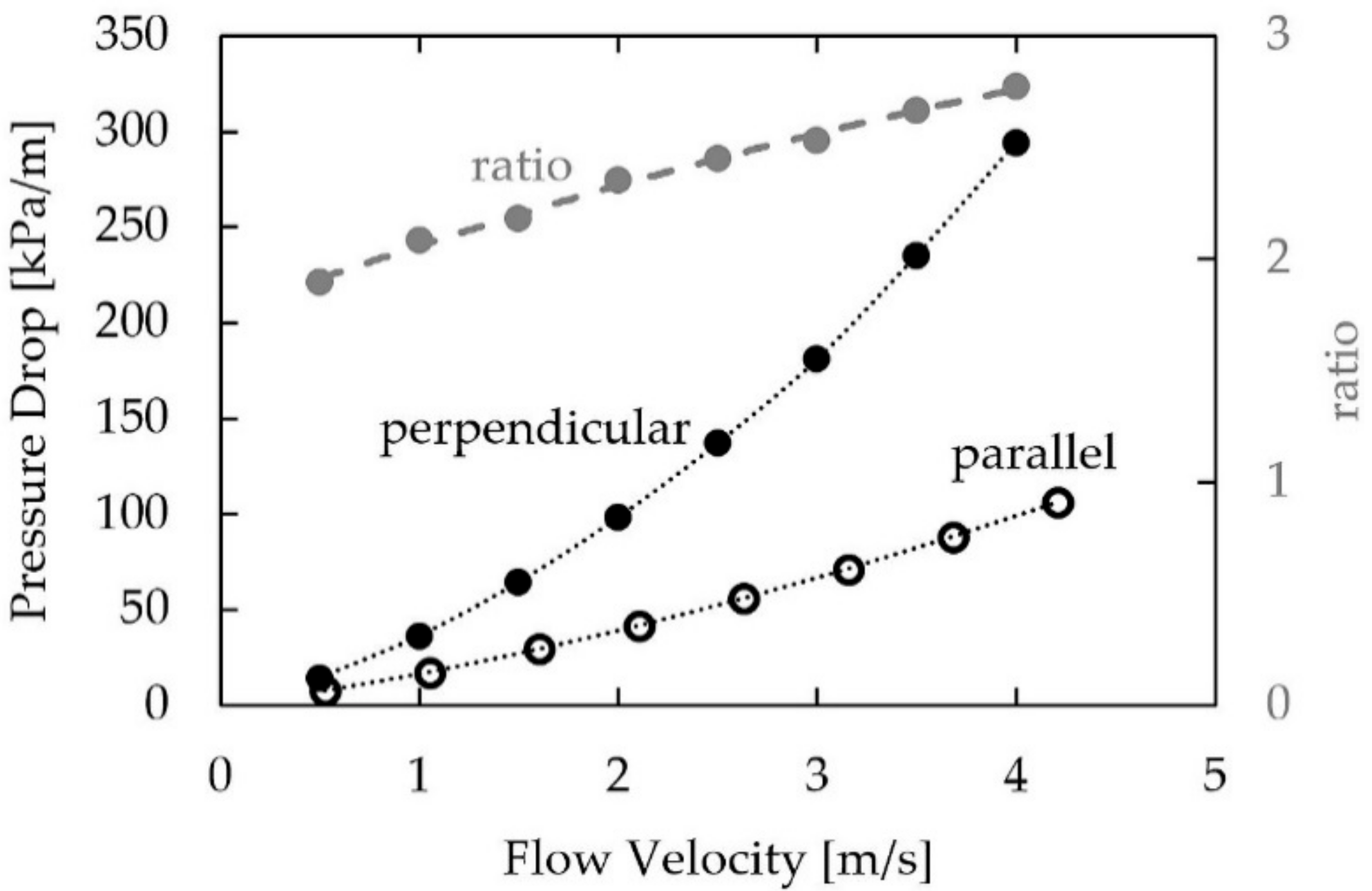
4.3. Pressure Drop of Expanded Sheet Metal Structures

Pressure drop was measured on a sample with dimension 100 mm × 10 mm × 10 mm. Thus, the sample can be rotated by 90° without changing the flow path length of 10 mm through the structure. This way, the influence of the sample orientation (flow direction perpendicular or parallel to the expanded sheet metal layer) could be measured in the same setup. The measurements were carried out with air at an ambient pressure and temperature.
The internal structure of expanded sheet metal structures (Figure 13) consists of thin layers and wide mesh openings, which are likely to produce a different pressure drop in the two major orientations (perpendicular and parallel to the layer) of the structure. Figure 14 shows the pressure drop per unit length of a structure with 77% porosity parallel and perpendicular to the expanded sheet metal layer. In accordance with the above comment on linear pressure drop, these values are tentative, as we did not systematically check whether the sample thickness was sufficient to produce a stationary velocity profile. However, since the size of the openings is in the order of tenth of millimeters and the sample thickness measures 10 mm, there is a high probability that the entrance length is much smaller than the sample thickness.
Obviously, the pressure drop is higher when the air flows along the perpendicular direction. At lower incident flow velocities, the difference in pressure loss is smaller, but the ratio increases nearly linearly, as shown in Figure 14. Originally, it was expected that the large mesh openings of the individual expanded sheet metal layers should lead to a good permeability of the structure. However, in perpendicular direction to the mesh plane, the fluid must flow around many individual obstacles (as illustrated by the cross section in Figure 13) with an unfavorable orientation posed by 200 layers of expanded sheet metal. Thus, it turns out that the pressure drop is in fact larger along this direction.
The difference between the two directions is quite pronounced and rises with increasing flow velocity. At 1 m/s the pressure drop perpendicular to the structure is higher by a factor of 2.1 than in the parallel direction, and this factor rises to 2.8 at an incident flow velocity of 4 m/s. The most likely explanation for this behavior can be seen in an increasingly turbulent flow around the square-edged struts at higher flow velocities.

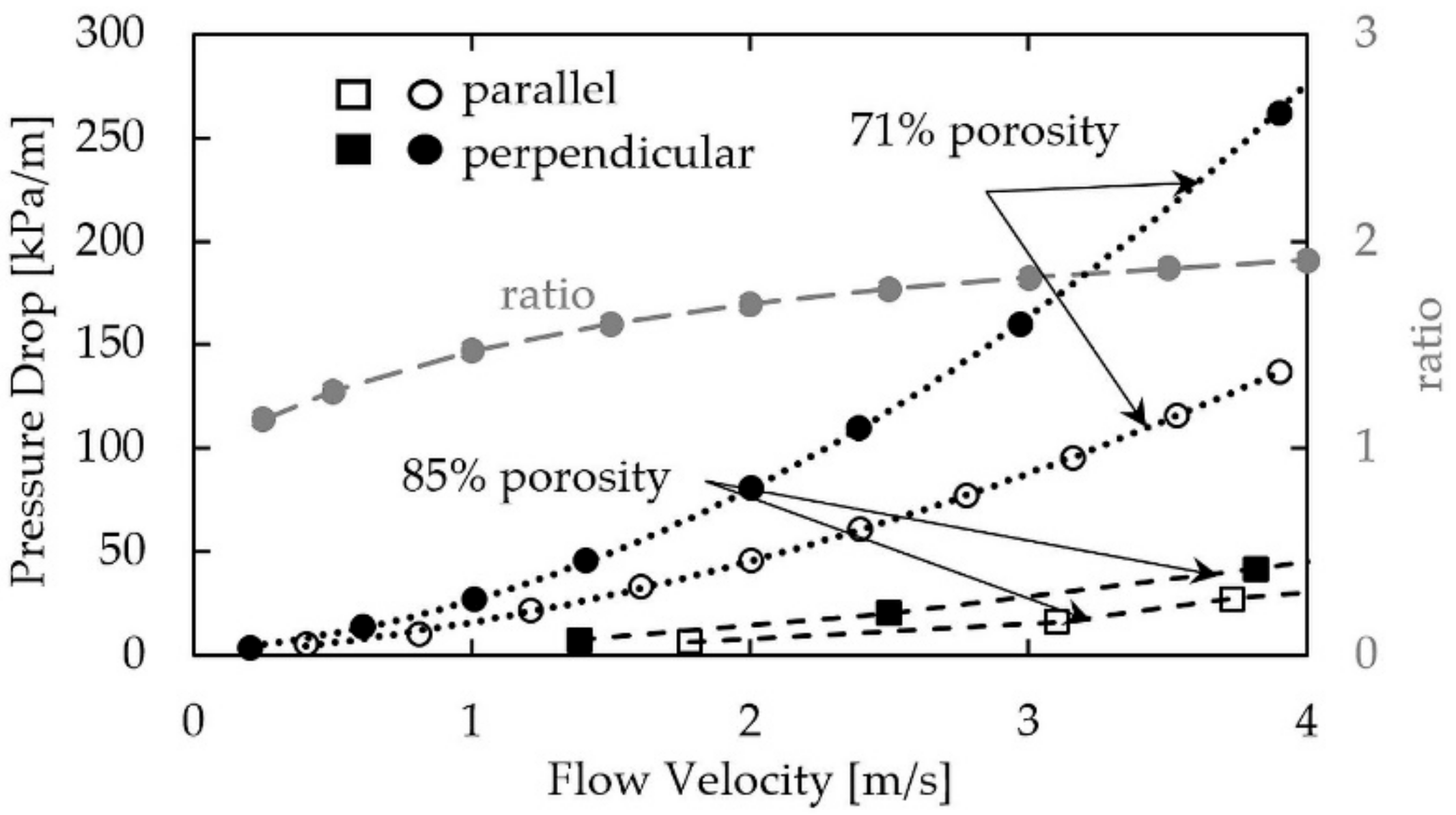
4.4. Pressure Drop of Fiber Structures

Before the first fiber structures for thermal applications were developed, the pressure drop of sintered fiber structures was already investigated in conjunction with filtration applications. Andersen et al., have shown a clear directional dependence of pressure drop on flow orientation in FeCrAl short-fiber structures [3], and they also identified an analytical model with a good fit when the fluid flow is perpendicular to the isotropic plane [35]. Huang et al. [36] calculated the pressure drop based on a length-weighted orientation model. However, the simulation results were not validated appropriately by experimental results.
For the current measurements of AlSi1 short-fiber structures with different porosities, again samples with dimension 100 mm × 30 mm × 10 mm were used. The measurements were carried out with air at ambient pressure and temperature. Figure 15 shows the pressure drop of two different short-fiber structures with porosity 71% and 85% for two orientations. In accordance with the above comment on linear pressure drop, these values are tentative, as we did not check systematically whether the sample thickness was sufficient to produce a stationary velocity profile. However, since the size of the pores is in the order of tenth of millimeters and the sample thickness measures 10 mm, there is a high probability that the entrance length is much smaller than the sample thickness. Again, the direction of airflow was parallel and perpendicular to the isotropic plane. It is obvious that a lower pressure drop was measured parallel to the isotropic plane. Depending on the orientation, at an inflow velocity of 4 m/s, the pressure drop in the same short-fiber structure but with a different orientation differs by a factor of 1.5 (85% porosity) and 1.9 (71% porosity), respectively.
The reason for this difference is the same, as in the case of the expanded sheet metal structures. The fibers are statistically oriented in the isotropic plane or only slightly inclined towards this plane. Therefore, depending on the direction of flow, they are flowed around either preferentially laterally or transversely (Figure 16). The fibers are in a more unfavorable orientation with a high drag coefficient when the airflow is perpendicular to the isotropic plane. Each transverse fiber acts as a strong obstacle to the flow leading to a high-pressure drop. Parallel to the isotropic plane, the fibers are on the average more often oriented in parallel to the flow direction, and it therefore generates less drag. Additionally, the number of forced flow detours is lower along this direction. Overall, this leads to a lower pressure drop parallel to the isotropic plane.
Since the fibers are more rounded than the struts of the sheet metal structure, they should create less turbulence. In fact, the trend of a drifting pressure drop is not very pronounced. In the case of the less porous structure, at 0.6 m/s the pressure drop perpendicular to the structure is by a factor of 1.7 higher than in the parallel direction and this factor rises to 1.9 at an incident flow velocity of 4 m/s. Hence, the spread is much lower than observed in the sheet metal structure.
However, expanded sheet metal structures create a lower pressure drop than fiber structures. When comparing the low pressure drop orientation at 1 m/s flow velocity, an expanded sheet metal structure of 77% porosity shows a pressure drop of 17.5 kPa, whereas a fiber structure of higher porosity of 85% creates a pressure drop of 20 kPa. This difference is even more pronounced at higher flow velocities. At 4 m/s the expanded sheet metal structure shows a pressure drop of 100 kPa and the fiber structure has a pressure drop of 140 kPa.

5. Applications

In the case of orthotropic structures, their special direction-dependent properties must always be taken into account when thinking about new applications. Some applications under research or in the demonstration stage are given below with emphasis on the orientation of the structure.

5.1. Application of Lotus-Type Structures

Lotus-type structures can be possible solutions for cooling i.e., as heat sinks [1,2]. As shown in Figure 17, for this application a copper plate is joined parallel to the pores on a lotus-type structure. A fluid flows through the elongated pores. Due to the enlarged inner surface of the structures, a good heat exchange between the porous structure and the fluid exists. Since the heat flow is usually through the joined copper plate, it is perpendicular to the pore. Thus, the poorer structural orientation for heat conduction is used. Since the loss in heat conducting performance is at its maximum 35%, the heat transfer from the fluid to the structure is probably the primary limiting factor for the performance.
The recently developed UniPore structures have already been tested as heat capacitors [1]. Buffering and storing of large amounts of heat is possible by the application of wax that is used as phase change material (PCM), which is filled into the pores of the structure (Figure 18). The phase transition of the PCM from solid to liquid requires large amounts of energy, which is used here to store the heat at constant temperature. The UniPore structure acts as container and it enhances the heat transfer into the PCM, which itself has itself a very poor heat conductivity. The heat flow was oriented parallel to the pores so that the optimal thermal conductivity of the structure was used. Heating was carried out with a power of 50 W and 100 W and the temperature of the heat source was determined. Results show that that the temperature of the heat source rises much more slowly when applying the heat capacitor. For example, at an energy input of 50 W, after 100 s of heating time the temperature increased only by 20 K when using the structures as a heat buffer, whereas without it, the temperature increased by 50 K.

5.2. Application of Metal Fiber Structures

Sintered short-fiber structures have already shown their advantageous properties in various applications. Whether used as a regenerator in Stirling engines [37], as a heat distributor for fast latent heat accumulators/capacitors [38], thermal conditioning devices for solar panels [4], or as a fin replacement in heat exchangers for sorption heat pumps or sorption cooling [6], there has always been an improvement in performance.
Sorption heating and cooling makes use of the chemical adsorption i.e., of water in zeolites and the condensation and evaporation of the working fluid (i.e., water). However, zeolite has low heat conductivity, leading to poor power densities in commercial sorption driven heating and cooling devices. A way out is fiber structures that are coated with zeolite. Due to the large surface area of the fiber structure, large amounts of zeolite can be coated onto the fibers and the high heat conductivity of the fiber structure enhances the heat transfer into the zeolite. Additionally, uncoated fiber structures can enhance evaporation and condensation, which are processes in a sorption heat pump or cooling, too.
In order to test fiber structures for sorption driven heating and cooling, heat exchangers with aluminum short-fiber structures instead of the typical fin structure were manufactured (Figure 19). The sorption module for experiments had four heat exchangers, each with a total volume of 10 L and a surface area of 60 m2. Of these, two heat exchangers were coated with zeolite and acted as adsorber/desorber, and two were used in the uncoated state as water evaporators/condensers. The sorption module applying aluminum short-fiber structures showed a three- to four-fold increase in power density when compared to fin type modules.
However, for ease of manufacturing, the short-fiber structures were not used in the ideal orientation. The heat had to flow perpendicular to the good heat conducting isotropic plane to and from the flat tubes carrying the water flow. Consequently, further improvements of the sorption module performance should be possible by the using a correct alignment of the short-fiber structure. Recently, such a heat exchanger has been manufactured where the heat flow is parallel to the isotropic plane. Testing of this heat exchanger is underway.
Heat exchangers that are made from copper could be used as carriers for metal-organic frameworks. For this purpose, copper long-fiber structures or expanded sheet metal structures could replace the copper fins of ordinary fin-type heat exchangers.
A fast latent heat storage device was developed at Fraunhofer IFAM Dresden [38,39]. AlCu5 short fiber structures were used as a heat transfer structure to enhance the heat transport into the PCM in order to accelerate the melting of the PCM and thus to shorten the charging/discharging time of latent heat storage devices. This device could be used to buffer intermittent waste heat from industrial processes, which could be transferred to the buffer via a heat carrying fluid. Tubes bearing the fluid are connected to the short-fiber structure (Figure 20). In this case, it was possible to utilize the good heat conducting properties of the isotropic plane, as it is oriented perpendicular to the tube. Consequently, the heat transport into the PCM, which is contained in the pores of the short-fiber structure, was greatly enhanced. This leads to a dramatic shortening of the charging time i.e., of an eight-liter volume of PCM from over one hour down to 11 min. The maximum storage capacity was 0.4 kWh, however, the cycling tests were carried out between 10% and 90% charging level. For these boundary conditions, the thermal peak power reached 12 kW and was on the average 2 kW. In the case under investigation, the reduction of the charging time by a factor of six brings about only a small loss of storage capacity of 20% due to the built-in short-fiber structure. Depending on the fluid temperature, the applied PCM, the porosity of the structure, and several other parameters, like the tube spacing and fluid flow rate, the charging and discharging times can be tailored according to the requirements of the specific application.
The same favorable approach can be transferred to related applications. Recently, Klemm et al. [4] showed a modular heat capacitor for the passive cooling of photovoltaic (PV) panels. The device allows for thermal management that absorbs heat from the solar panel by day (20 K lower maximum temperature) and releases the heat to the module during night (preventing condensation of water on the PV panel). Especially, in hot areas like the Middle East, this can enhance the performance and service life time of PV power plants due to a higher efficiency of the solar panel, and due to prevention of soiling.
A similar passive cooling approach was tested for the thermal management of batteries used in electric cars. Since an active cooling system of the battery in an electric car consumes valuable electric energy and therefore decreases the attainable range, thus a passive solution is desirable. Figure 21 shows a concept drawing of passive cooling with AlSi1 short-fiber structures and PCM. A representative test setup was evaluated under laboratory conditions. The AlSi1 short-fiber structure was joined to a fluid-cooled metal plate. The isotropic plane of the short-fiber structure was perpendicular to the plate. The structure had a porosity of 80% and it was filled with a PCM with a slightly lower melting point than the optimum working temperature of the battery cells. In this application, heat transfer is required in two directions: during driving, heat has to be transferred from the battery cell to the PCM and during fast charging from the battery to the cooling plate that is actively cooled (Figure 21). Therefore, an orientation of the short-fiber structure was chosen such that the well-conducting direction pointed towards the cooling plate. However, the heat conductivity perpendicular to the isotropic plane was still high enough to significantly enhance the heat transfer from the battery cell into the PCM. Consequently, the heat that was generated by the battery cells was transferred into the whole PCM volume by the fiber structure and was stored at the melting temperature of approximately 35 °C.
The New European Driving Cycle was used to determine the generation of heat for city and highway driving conditions of large prismatic or pouch cells that are similar to the cells used in a BMW i3. Additionally, fast charging was modelled as a high-power condition. Battery dummy cells with properties similar to original battery cells were used for a realistic evaluation of the thermal results. Several thermocouples measured the temperature distribution in these cells. Due to the passive cooling and the constant temperature at the melting point of the PCM, the temperature distribution was close to homogenous throughout the whole cell and it differed only by 1 K, even under high-power conditions. The temperature of the battery within the simulation of driving could be kept below 35 °C at all times (Figure 22). After driving, the charging of the battery made use of the active cooling by the cooling plate. Since the fibers were oriented towards the cooling plate in the highly heat-conducting direction, heat transfer reached an optimum, cooling and re-solidifying the PCM for the next driving cycle. When fast charging is applied, the lateral cooling of the battery cell leads to a temperature of only 40 °C, starting from room temperature. Since the vehicle is connected to the electric grid during fast charging, the power for the active cooling system does not have to be taken from the vehicle battery.
Besides the thermal management of the battery during driving and charging, the PCM constitutes a passive thermal protection for the battery. If a short-circuit or malfunction of the battery occurs, then the PCM stores the released heat from the battery and prevents a temperature increase (“thermal runaway”). An active system would have to be activated to cool the battery, whereas the PCM cooling is available at all times.

6. Conclusions and Outlook

Apart from the well-investigated open porous metallic sponges, there exists anisotropic structures with pronounced directional dependencies of the heat and fluid flow properties. Correctly applied, these features can be used to achieve considerable improvements in thermal applications. The relevant properties that are discussed in this paper are the heat conductivity and the pressure drop. Both are crucial for thermal applications, however, the anisotropy also holds for mechanical or electrical properties, too.
Depending on the type of structure and the manufacturing process, the value of the direction-dependent heat conductivity may differ by a factor of 2 to 25. The influence of the measurement direction is less pronounced for the pressure drop; here, the difference varies between a factor of 1.5 to 2.8. The reason for the large variation of the heat conductivity is on the one hand the morphology, on the other hand, the type of bonding between the fibers or expanded metal sheet structures. Solid-phase sintering provides only small sinter necks that constitute a bottleneck for the heat flow, whereas liquid-phase sintering provides much large sinter bonds, which are beneficial for the heat transport. Therefore, the lowest heat conductivities are always observed for structures that were solid-phase sintered.
The nature of the sinter bonds is less decisive for the pressure drop as they do not create a significant amount of drag when compared to the rest of the structure. Therefore, the directional differences in pressure drop are mainly dominated by the orientation of the fibers or expanded sheet metals towards the fluid flow direction.
The presented structures constitute a special case of orthotropy. Lotus-type structures as well as fiber structures show a transverse isotropy with a single isotropic plane. Expanded sheet metal structures feature an orthotropy that is characterized by a rotational symmetry of 90° for one spatial axis only, instead of 180° for all the orthogonal spatial axes. These directional anisotropies lead to different properties depending on the orientation of the structure and with regard to the formal description of the properties. Due to this special orthotropic symmetry, for all structures, only two orientations of the material are of interest.
Special attention has to be paid to the validity of the applied measurement techniques. For the measurement of the heat conductivity, a steady-state plate method is preferred. Here, the contact conditions and the applied reference materials are of utmost importance. Without knowing the respective measurement conditions in detail, it is hardly possible to compare the results taken from literature. In any case, it is advisable to use the same contact conditions as those that are encountered in the real application.
The investigated structures feature quite different properties. Lotus-type structures show unidirectional pores, resulting in only one direction that permits the through-flow of fluids. Consequently, their properties can be altered only by changing the pore diameter and the total porosity. Here, the heat conductivity depends mainly on the total porosity, therefore only the pressure drop can be tuned by changing the pore size. However, lotus-type structures represent the only open-porous structure with a linear dependence of the heat conductivity on porosity and show the smallest difference of the heat conductivity in the two main directions. This leads to the best heat conductivity, but unfortunately, the porosity is limited to approximately 60% in conventional manufacturing. Additive manufacturing would certainly be capable of producing structures with much higher porosities. The elongated pores lead to a low pressure drop, predominantly due to laminar flow conditions. Due to the regular structure, analytical models can be adapted to lotus-type structures and lead to good agreement between experiment and calculations.
The high heat conductivity, low pressure drop and their predictability make lotus-type structures suitable for fast heat capacitors and heat sinks with a flowing cooling agent. On the other hand, the unidirectional low open porosity restricts the range of potential applications.
Among the reviewed structures, fiber structures are the most versatile option regarding thermal applications. Their properties can be influenced in a wide range i.e., by using short or long fibers, different fiber diameters and cross-sectional shapes, different degrees of fiber alignment, and applying either solid-state or liquid-phase sintering for the bonding of individual fibers. These manufacturing options allow for the tailoring of several parameters, like total porosity, specific surface area, degree of directional dependence of heat conductivity, and pressure drop. Thus, it is difficult to derive an analytical model or a general law for the properties of fiber structures that fits all possibilities. Despite their poor predictability, they have shown experimentally improved power density in several applications, ranging from heat exchangers and thermal storage devices all the way to adsorbers and evaporators. Although dramatic improvements could be demonstrated in practical tests, in some cases, it remains an open question whether the optimum configuration has been already achieved. For further optimization, it is necessary to conduct extensive parameter studies of structures, holding constant certain parameters that are important for the application, i.e., a certain pore size or a constant heat conductivity and porosity. Although fiber structures are often compared to sponges, they are especially different in terms of the attainable porosity (60% to 90%) and pore size. Depending on the fiber diameter and the total porosity, the pore size is usually considerably smaller than that of sponges and ranges from some µm to some hundred µm. Additionally, the heat conductivity is better in the highly heat-conducting orientation.
Expanded sheet metal structures provide a smaller freedom of design than fiber structures, but a higher one than lotus-type structures. In particular, the possibility to change the heat conductivity perpendicular to the expanded sheet metal layers is quite restricted. It can only be increased by providing larger sinter necks, i.e., by using liquid phase sintering, which is not possible for every metal. Another option would be to use brazing instead of sintering. In the direction of the expanded sheet metal layer, changing the mesh size, mesh shape and strut or layer thickness is technically possible and would change the properties along the layer. Thus, the difference in properties becomes tunable to a certain extent. Due to the regularity of a single layer, it should be possible to derive an analytical model for the prediction of the different properties for thermal applications. Further research should therefore focus on such a model and its validation in order to facilitate the design of new or improved thermal devices. Especially, heat exchangers and latent heat storage devices may benefit from small pore sizes, high heat conductivity, and, when compared to fiber structures, a lower pressure drop.

Author Contributions

M.F.: Wrote a major part of the paper and lead the project HARVEST where especially the results on expanded sheet metal structures were achieved. O.A.: Wrote parts of the paper and made major revisions. Additionally, lead projects where some of the results come from. A.S.: Wrote the part about the measurement setups. T.S.: Conducted some experiments, especially on battery cooling, and revised the paper in some parts.

Funding

The results presented here were achieved in the course of several projects. In particular, the authors would like to thank the Fraunhofer-Zukunftsstiftung for funding of the project HARVEST, the Fraunhofer-Gesellschaft zur Förderung der angewandten Forschung e.V. for funding of the project OSTEF, the Bundesministerium für Bildung und Forschung for funding of the project FaserPCM (Funding No. 01LY1019A), and the Bundesministerium für Wirtschaft und Energie for funding of the project ADOSO (Funding No. 03ET1127B).

Conflicts of Interest

The authors declare no conflict of interest. The funding sponsors had no role in the design of the study; in the collection, analyses, or interpretation of data; in the writing of the manuscript, and in the decision to publish the results.

References

  1. Fiedler, T.; Borovinšek, M.; Hokamoto, K.; Vesenjak, M. High-performance thermal capacitors made by explosion forming. Int. J. Heat Mass Transf. 2015, 83, 366–371. [Google Scholar] [CrossRef]
  2. Liu, Y.; Chen, H.F.; Zhang, H.W.; Li, Y.X. Heat transfer performance of lotus-type porous copper heat sink with liquid GaInSn coolant. Int. J. Heat Mass Transf. 2015, 80, 605–613. [Google Scholar] [CrossRef]
  3. Andersen, O.; Kostmann, C.; Stephani, G.; Korb, G. Application-related properties of sintered metallic fiber structures. In Cellular Metals, Proceedings of MetFoam, 2003; Banhart, J., Fleck, N.A., Mortensen, A., Eds.; MIT Publ.: Berlin, Germany, 2003; pp. 481–486. [Google Scholar]
  4. Klemm, T.; Hassabou, A.; Abdallah, A.; Andersen, O. Thermal energy storage with phase change materials to increase the efficiency of solar photovoltaic modules. Energy Procedia 2017, 135, 193–202. [Google Scholar] [CrossRef]
  5. Zhao, C.Y. Review on thermal transport in high porosity cellular metal foams with open cells. Int. J. Heat Mass Transf. 2012, 55, 3618–3632. [Google Scholar] [CrossRef]
  6. Wittstadt, U.; Füldner, G.; Andersen, O.; Herrmann, R.; Schmidt, F. A new adsorbent composite material based on metal fiber technology and its application in adsorption heat exchangers. Energies 2015, 8, 8431–8446. [Google Scholar] [CrossRef]
  7. Velte, A.; Herrmann, R.; Andersen, O.; Wittstadt, U.; Füldner, G.; Schnabel, L. Experimental characterization of aluminum Fibre/SAPO-34 composites for adsorption heat pump applications. In Proceedings of the Heat Powered Cycles Conference, Nottingham, UK, 27–29 June 2016; Eames, I.W., Tierney, M.J., Eds.; [Google Scholar]
  8. Veyhl, C.; Fiedler, T.; Andersen, O.; Meinert, J.; Bernthaler, T.; Belova, I.V.; Murch, G.E. On the thermal conductivity of sintered metallic fibre structures. Int. J. Heat Mass Transf. 2012, 55, 2440–2448. [Google Scholar] [CrossRef]
  9. Fiedler, T.; Veyhl, C.; Belova, I.V.; Tane, M.; Nakajima, H.; Bernthaler, T.; Merkel, M.; Öchsner, A.; Murch, G.E. On the Anisotropy of Lotus-Type Porous Copper. Adv. Eng. Mater. 2012, 14, 144–152. [Google Scholar] [CrossRef]
  10. Veyhl, C. Numerical and Experimental Analysis of Advanced Cellular Materials. Ph.D. Thesis, University of Newcastle Australia, Newcastle, Australia, October 2012. [Google Scholar]
  11. Belova, I.V.; Veyhl, C.; Fiedler, T.; Murch, G.E. Analysis of anisotropic behaviour of thermal conductivity in cellular metals. Scr. Mater. 2011, 65, 436–439. [Google Scholar] [CrossRef]
  12. Shapovalov, V. Porous Metals. MRS Bull. 1994, 19, 24–28. [Google Scholar] [CrossRef]
  13. Chiba, H.; Ogushi, T.; Nakajima, H. Heat transfer capacity of lotus-type porous copper heat sink for air cooling. J. Therm. Sci. Technol. 2010, 5, 222–237. [Google Scholar] [CrossRef]
  14. Nakajima, H.; Ikeda, T.; Hyun, S.K. Fabrication of Lotus-type Porous Metals and their Physical Properties. Adv. Eng. Mater. 2004, 6, 377–384. [Google Scholar] [CrossRef]
  15. Nakajima, H. Fabrication, properties, and applications of porous metals with directional pores. Proc. Jpn. Acad. Ser. B 2010, 86, 884–899. [Google Scholar] [CrossRef] [Green Version]
  16. Muramatsu, K.; Ide, T.; Nakajima, H.; Eaton, J.K. Heat Transfer and Pressure Drop of Lotus-Type Porous Metals. J. Heat Transf. 2013, 135, 72601. [Google Scholar] [CrossRef]
  17. Dukhan, N. Metal Foams: Fundamentals and Applications; Destech Publications: Lancaster, PA, USA, 2013; ISBN 9781605950143. [Google Scholar]
  18. Kim, T.B.; Tane, M.; Suzuki, S.; Nakajima, H. Pore Morphology of Porous Al-Ti Alloy Fabricated by Continuous Casting in Hydrogen Atmosphere. Mater. Trans. 2010, 51, 1871–1877. [Google Scholar] [CrossRef] [Green Version]
  19. Hyun, S.K.; Nakajima, H. Effect of solidification velocity on pore morphology of lotus-type porous copper fabricated by unidirectional solidification. Mater. Lett. 2003, 57, 3149–3154. [Google Scholar] [CrossRef]
  20. Hokamoto, K.; Shimomiya, K.; Nishi, M.; Krstulović-Opara, L.; Vesenjak, M.; Ren, Z. Fabrication of unidirectional porous-structured aluminum through explosive compaction using cylindrical geometry. J. Mater. Process. Technol. 2018, 251, 262–266. [Google Scholar] [CrossRef]
  21. Hayashida, T.; Suzuki, S.; Ichikawa, J.; Toyoyama, R. Fabrication of Porous Aluminum Alloys with Aligned Unidirectional Pores by Dipping Pipes into Liquid and Semi-solid base Metals. Proc. Mat. Sci. 2014, 4, 85–89. [Google Scholar] [CrossRef]
  22. Andersen, O.; Meinert, J.; Studnitzky, T.; Stephani, G.; Kieback, B. Highly heat conductive open-porous aluminium fibre based parts for advanced heat transfer applications. Materiawiss. Werkstofftech. 2012, 43, 328–333. [Google Scholar] [CrossRef]
  23. Neelakantan, S.; Bosbach, W.; Woodhouse, J.; Markaki, A.E. Characterization and deformation response of orthotropic fibre networks with auxetic out-of-plane behaviour. Acta Mater. 2014, 66, 326–339. [Google Scholar] [CrossRef]
  24. Tang, Y.; Zhou, W.; Xiang, J.; Liu, W.; Pan, M. An Innovative Fabrication Process of Porous Metal Fiber Sintered Felts with Three-Dimensional Reticulated Structure. Mater. Manuf. Process. 2010, 25, 565–571. [Google Scholar] [CrossRef] [Green Version]
  25. DIN. Thermal Performance of Building Materials and Products—Determination of Thermal Resistance by Means of Guarded Hot Plate and Heat Flow Meter Methods—Dry and Moist Products of Medium and Low Thermal Resistance; DIN EN 12664:2001-05; German version EN 12664:2001; DIN: Berlin, Germany, 2001. [Google Scholar]
  26. DIN. Thermal Performance of Building Materials and Products—Determination of Thermal Resistance by Means of Guarded hot Plate and Heat Flow Meter Methods—Products of High and Medium Thermal Resistance; DIN EN 12667:2001-05; German version EN 12667:2001; DIN: Berlin, Germany, 2001. [Google Scholar]
  27. DIN. Thermal Performance of Building Materials and Products—Determination of Thermal Resistance by Means of Guarded Hot Plate and Heat Flow Meter Methods—Thick Products of High and Medium Thermal Resistance; DIN EN 12939:2001-02; German version EN 12939:2000; DIN: Berlin, Germany, 2001. [Google Scholar]
  28. Schlott, A.; Zimmermann, S.; Andersen, O.; Meinert, J.; Kieback, B. Impact of sample preparation on the accuracy of heat conductivity measurements of metal fiber structures. In Proceedings of the CelMat 2014, Dresden, Germany, 22–24 October 2014. [Google Scholar]
  29. Yang, X.H.; Bai, J.X.; Yan, H.B.; Kuang, J.J.; Lu, T.J.; Kim, T. An Analytical Unit Cell Model for the Effective Thermal Conductivity of High Porosity Open-Cell Metal Foams. Transp. Porous Media 2014, 102, 403–426. [Google Scholar] [CrossRef]
  30. Ogushi, T.; Chiba, H.; Nakajima, H.; Ikeda, T. Measurement and analysis of effective thermal conductivities of lotus-type porous copper. J. Appl. Phys. 2004, 95, 5843–5847. [Google Scholar] [CrossRef]
  31. Behrens, E. Thermal conductivities of composite materials. J. Compos. Mater. 1968, 2, 2–17. [Google Scholar] [CrossRef]
  32. Ashby, M.F. Metal Foams: A Design Guide; Butterworth-Heinemann: Boston, UK, 2000; ISBN 9780080511467. [Google Scholar]
  33. Ranut, P. On the effective thermal conductivity of aluminum metal foams: Review and improvement of the available empirical and analytical models. Appl. Therm. Eng. 2016, 101, 496–524. [Google Scholar] [CrossRef]
  34. Veyhl, C.; Belova, I.V.; Murch, G.E.; Öchsner, A.; Fiedler, T. Thermal analysis of aluminium foam based on micro-computed tomography. Materiawiss. Werkstofftech. 2011, 42, 350–355. [Google Scholar] [CrossRef] [Green Version]
  35. Andersen, O.; Meinert, J. Heat Transfer and Fluid Flow in Sintered Metallic Fiber Structures. Mater. Sci. Forum 2010, 638, 1884–1889. [Google Scholar] [CrossRef]
  36. Huang, X.; Zhao, Y.; Wang, H.; Qin, H.; Wen, D.; Zhou, W. Investigation of transport property of fibrous media: 3D virtual modeling and permeability calculation. Eng. Comput. 2017, 33, 997–1005. [Google Scholar] [CrossRef]
  37. Kostmann, C.; Andersen, O.; Gimsa, A.; Domann, L. Sintered Metal Fiber Structures for Fast Heat Storage and Regeneration. In Proceedings of the CELLMET2008: International Symposium on Cellular Metals for Structural and Functional Applications, Dresden, Germany, 8–10 October 2008; Stephani, G., Kieback, B., Eds.; pp. 24–29. [Google Scholar]
  38. Andersen, O.; Meinert, J.; Göhler, H.; Kieback, B. Application of powder metallurgy in the development of fast PCM heat accumulators for domestic and industrial heat storage. In Proceedings of the International Porous and Powder Materials Symposium and Exhibition PPM 2015, İzmir, Turkey, 15–18 September 2015; Sevgi, K.Ö., Polat, M., Tanoğlu, M., Eds.; pp. 7–11. [Google Scholar]
  39. Andersen, O.; Enders, T.; Fieback, K.; Lindenberg, G.; Meinert, J.; Schubert, V. Latent heat storage element comprises housing that is closed in a fluid tight manner and includes tubular conduit for temperature medium, metallic open-pore structure in space within housing and tubular conduit, and phase change medium. Patent No. DE102012005359 A1, 13 March 2012. [Google Scholar]
Figure 1. Section of a lotus-type porous copper ingot. Reproduced from [2], with permission from Elsevier, 2015.
Metals 08 00554 g001
Figure 2. (a) Stereo microscopy image of expanded metal layer with open area of up to 80% and diamond shaped mesh for (b) sintered expanded sheet metal structure.
Metals 08 00554 g002
Figure 3. Microscopy image of an expanded sheet metal structure cross section. Arrows indicate sinter necks between single layers.
Metals 08 00554 g003
Figure 4. Photography of (a) AlSi1 short-fiber structure made from short metal fibers and (b) photography of copper long-fiber structure made from endless copper fibers. Arrows indicate the normal vector of the isotropic plane.
Metals 08 00554 g004
Figure 5. Schematic drawing of the steady-state plate method and detail of sample connection.
Metals 08 00554 g005
Figure 6. Heat conductivity of lotus-type structures in parallel and perpendicular direction of the pores [17].
Metals 08 00554 g006
Figure 7. Heat conductivity along two different directions of an expanded sheet metal structure. The grey dotted line indicates a theoretical linear dependency of the heat conductivity on the porosity.
Metals 08 00554 g007
Figure 8. Heat conductivity of metal fiber structures in the two major directions (parallel and perpendicular to isotropic plane) and heat conductivity of an aluminum foam.
Metals 08 00554 g008
Figure 9. Cross section of (a) an AlSi1 short-fiber structure and (b) copper long-fiber structure. Arrows indicate selected fiber-to-fiber bonds.
Metals 08 00554 g009
Figure 10. Schematic diagram of the test facility.
Metals 08 00554 g010
Figure 11. Construction of the cylindrical flow channel.
Metals 08 00554 g011
Figure 12. Schematic drawing of lotus-type structure samples for pressure drop measurement. Reproduced from [13], with permission from The Japan Society of Mechanical Engineers and The Heat Transfer Society of Japan, 2010.
Metals 08 00554 g012
Figure 13. Micrograph of an expanded sheet metal structure cross section with 77% porosity. Arrows indicate flow directions (arrow colors correspond to arrows in Figure 2b).
Metals 08 00554 g013
Figure 14. Pressure drop of an expanded sheet metal structure parallel and perpendicular to the layers and the ratio of the pressure drop in different directions.
Metals 08 00554 g014
Figure 15. Pressure drop of two different aluminum short-fiber structures with fluid flow parallel and perpendicular to the isotropic plane.
Metals 08 00554 g015
Figure 16. Cross section of an AlSi1 short-fiber structure with a single fiber cut lengthwise (red arrow) and arrows indicating the direction of airflow (the orange arrow corresponds to the orange arrow in Figure 4a).
Metals 08 00554 g016
Figure 17. Lotus-type copper heat sink. Fluid flows through the pores and heat flows from the bottom into the structure. Reproduced from [2], with permission from Elsevier, 2015.
Metals 08 00554 g017
Figure 18. UniPore structure with 46.7% porosity filled with phase change material (PCM). Reproduced from [1], with permission from Elsevier, 2015.
Metals 08 00554 g018
Figure 19. (a) Assembly of a heat exchanger with AlSi1 short-fiber structures by stacking flat tubes and AlSi1 short-fiber structures. (b) Finished heat exchanger with AlSi1 short-fiber structure, total fiber structure volume 6.7 L, core dimensions 600 mm × 316 mm × 45 mm.
Metals 08 00554 g019
Figure 20. Photography of latent heat storage (without housing) before filling with PCM. Total fiber structure volume 8 L, dimensions of the fiber structure 200 mm × 200 mm × 200 mm.
Metals 08 00554 g020
Figure 21. Schematic drawing of a battery with single battery cells stacked with PCM filled fiber structures. An orange arrow marks the heat flow direction during active cooling during fast charging.
Metals 08 00554 g021
Figure 22. Temperature of individual battery cells during fast charging (active cooling) and two different driving situations (passive cooling).
Metals 08 00554 g022

