Laser Cladding In-Situ Ti(C,N) Particles Reinforced Ni-Based Composite Coatings Modified with CeO2 Nanoparticles


1
College of Mechanical and Electrical Engineering, Central South University, Changsha 410083, China
2
State Key Laboratory of High Performance Complex Manufacturing, Changsha 410083, China
*
Author to whom correspondence should be addressed.
†
The two authors contribute equally to this work.
Metals 2018, 8(8), 601; https://doi.org/10.3390/met8080601
Submission received: 7 July 2018
/
Revised: 27 July 2018
/
Accepted: 31 July 2018
/
Published: 2 August 2018
(This article belongs to the Special Issue Surface Treatment Technology of Metals and Alloys)
Abstract
:To improve the wear resistance of titanium alloy parts used in the engineering applications, in-situ formed Ti(C,N) particles reinforcing Ni-based composite coatings are fabricated on Ti6Al4V alloys by the laser cladding technique using Ni60, C, TiN, and small amounts of CeO2 nanoparticles mixed powders as the pre-placed materials. Firstly, the formation mechanism of Ti(C,N) particles as a reinforced phase in the coating is investigated. Then, the influences of CeO2 nanoparticles on microstructures and wear resistance of the coatings are analyzed. It is indicated that the large Ti(C,N) particles form around TiN particles, and the small Ti(C,N) particles form through independent nucleation. CeO2 nanoparticles play important roles in increasing the nucleation rate and improving the precipitation of Ti(C,N), hence the microstructures and wear resistance of the coatings are apparently improved after adding CeO2 nanoparticles. It is observed that the 1 wt % content of CeO2 additive in the pre-placed powders is the best choice for the wear resistance of the coatings.
1. Introduction
Nowadays, titanium alloys are widely applied in the aerospace and automotive fields owing to the high specific strength and excellent corrosion-resistant properties [1,2,3]. However, poor wear resistance has prevented them from being used as engineering tribological components [4,5]. It is well known that failures, such as wear and corrosion, usually start from the surface of the components, which tend to destroy the whole components. Therefore, in order to maintain excellent quality in titanium alloys and improve the tribological properties of their surface, a laser cladding process was widely applied to fabricate coatings on the titanium substrates [6,7,8]. Compared with the coatings fabricated by traditional surface modification techniques, such as nitriding, micro-arc oxidation, and thermal spraying, the coatings fabricated by the laser cladding process have the advantages of fine microstructure, small heat-affected zone, and strong metallurgical bonding with the substrates [9].
In order to fabricate high wear-resistant coatings, it is very important that suitable coating materials are chosen. Due to the characteristics of low melting point and good wettability, Ni-based self-fluxing alloy powders are frequently selected as the laser cladding materials [10,11]. Previous investigations indicated that it was beneficial to fabricate coatings with better wear resistance through adding hard ceramic particles into Ni-based self-fluxing alloy powders. For example, Dong et al. [12] fabricated in situ formed NbC/Ni-based composite coatings using (Nb + C)/Ni-based alloy powder mixture by the laser cladding and found that the wear resistance of the Ni-based alloy coatings was increased after adding the Nb + C particles, due to the reinforcement of the hard NbC phase. Li et al. [13] successfully obtained a Ni-based composite coating reinforced by in situ formed TiB2 and TiC particles by laser cladding. The average micro-hardness of the coating was 700 HV0.2, higher than that of the substrate due to the dispersion strengthening of the reinforcements. García et al. [14] investigated the effect of WC content on the microstructure and tribological properties of NiCrBSi/WC laser coatings and the results showed that the micro-hardness and wear resistance of the Ni-based alloy coatings containing the WC particles were significantly improved. Sun et al. [15] prepared NiCrBSi composite coatings reinforced by TiC particles on titanium alloy by laser cladding, and the wear resistance of the coatings were 8.8 times higher than that of the substrate.
In the laser cladding process, titanium carbonitride [Ti(C,N)], the solid solution of TiC and TiN, was also used as a reinforced phase in the fabrication of metal matrix composite (MMC) coating due to the superior mechanical properties, such as low friction, high hardness (HV 2500–3000), high melting point (3050 °C), electrical conductivity, and enhanced wear resistance [16]. Li et al. [17] fabricated TiC/TiN+TiCN reinforced Al3Ti/Ti3Al composite coatings by laser cladding process using Al3Ti+TiC+TiN pre-placed powders on titanium alloys, and the wear resistance of coatings was 4.5~5 times higher than that of the substrate. Yang et al. [18] obtained TiCN/Ti coatings by laser cladding of TiCN+Ti alloy powders on titanium alloys, and the wear properties of coatings were 4.2 times higher than that of the substrate. Furthermore, some researchers reported that the in-situ synthesis from the reaction between TiN and C was one of the most economical and effective methods for the preparation of Ti(C,N), which improved largely the wear resistance of the composite coatings [19,20]. However, studies concerning in-situ Ti(C,N) particles reinforced Ni-based composite coatings by using Ni60, C, and TiN mixed powders as the laser cladding materials have been rarely reported so far. In addition, cerium oxide (CeO2) nanoparticles were proven to effectively improve the microstructures and properties of cladding coatings due to their peculiar electronic structures and high chemical activity [21]. Wang et al. [22] investigated the effect of CeO2 on the microstructure and wear resistance of laser-clad Ni-based alloy coatings. The results revealed that the additive of CeO2 remarkably refined the microstructure and improved wear resistance of the cladding coatings. Zhang et al. [23] studied the effect of the content of nano-CeO2 added in Ni-based coatings on the coating quality. These researchers found that the wear resistance of coatings were greatly improved by CeO2 addition, and compared to the addition of 1.0% and 3.0%, 1.5% n-CeO2/NBA are the best. Although the influences of nano rare earth oxides on microstructures and properties of the materials are widely investigated, the studies concerning the effect of nano-CeO2 on the microstructures and properties of in-situ formed Ti(C,N)/Ni-based composite coatings by laser cladding are few [24,25].
Therefore, the work presented in this paper focuses on fabricating Ni-based composite coatings enhanced by in-situ synthesized Ti(C,N) by a laser cladding process using Ni60+C+TiN pre-placed powders on Ti6Al4V alloys. Moreover, the formation mechanism of Ti(C,N) and the influences of CeO2 nanoparticle addition on the microstructure and the wear resistance of the Ti(C,N)/Ni-based composite coatings are investigated.
2. Experimental Details
2.1. Materials Used
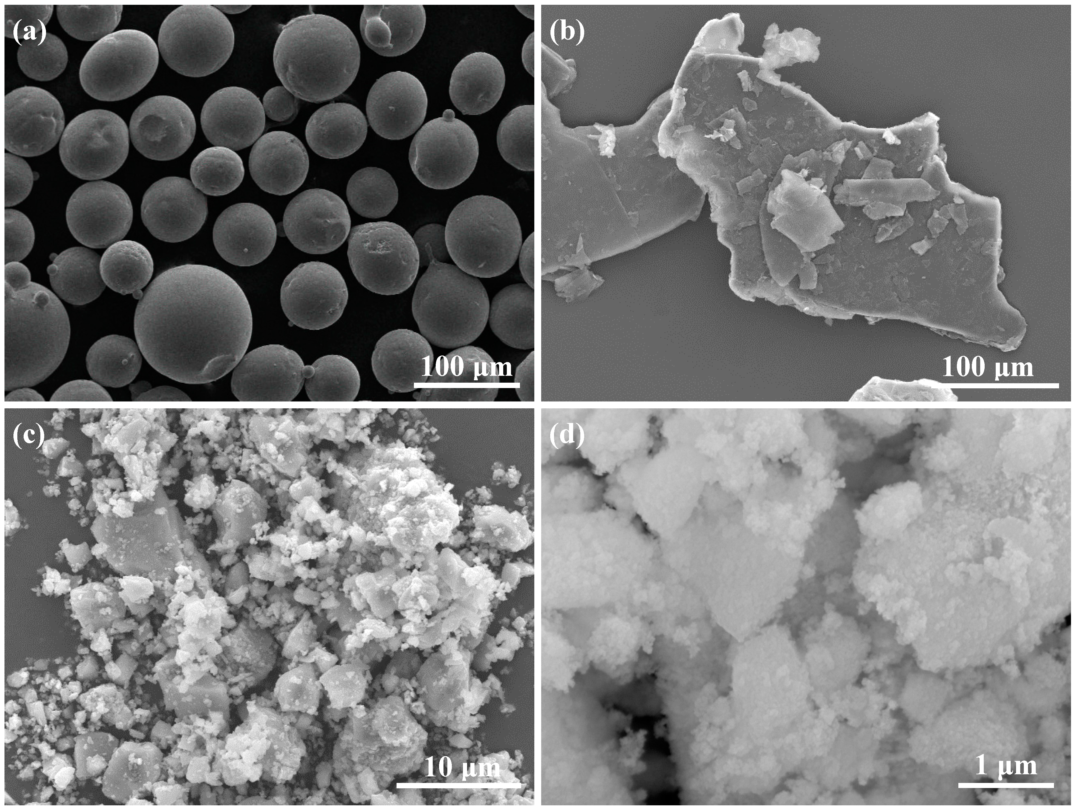
In this paper, Ti6Al4V alloy plates with dimensions of 30 mm × 30 mm × 6 mm are used as the substrates. All the substrates are polished by SiC grit paper (240#) and degreased with alcohol and acetone prior to the laser cladding experiments. The pre-placed powders for laser cladding are composited of NiCrBSi alloy powder (Ni60, particle size 40–100 µm, ≥99.5% purity), graphite (C, particle size 10–20 µm, ≥99.9% purity), titanium nitride (TiN, particle size 1–10 µm, ≥99.9% purity), and cerium oxide nanoparticle (CeO2, particle size 40 nm, ≥99.9%purity). Among them, the Ni60 and graphite powders were purchased from Nangong Xindun alloys spraying Co., Ltd (Nangong, China), and TiN and CeO2 powders were provided by Shanghai Naiou Nano technology Co., Ltd. (Shanghai, China). SEM images of the powders used in the present study for laser cladding are shown in the Figure 1. The chemical composition (in wt %) of the Ni60 alloy powders is listed in Table 1. It was reported that too little CeO2 additive could not effectively improve the wear resistance of cladding coatings; while too much CeO2 additive formed many inclusions, which markedly reduced the tribological properties of the coatings [22]. Therefore, the content of CeO2 nanoparticle additive in the pre-placed powders should be suitable. As shown in Table 2, to investigate the effect of amount of CeO2 nanoparticles additive on the behaviors of the coatings, different ratios of CeO2 powders in wt % are mixed in the basic pre-placed powders. According to the CeO2 additive contents of 0 wt %, 1 wt %, 2 wt %, and 3 wt % in the pre-placed mixed powders, the sample No. of the titanium plates modified by laser cladding process are marked as Sample 0, Sample 1, Sample 2, and Sample 3, respectively. Firstly, the powder mixtures are evenly stirred in a planetary ball mill for 3 hours. The mixed powders are blent with a polyvinyl alcohol binder and stirred until a slurry-like consistency is obtained, then the Ni60/C/TiN + binder slurry is placed in a rectangular slot with a size of 30.2 mm × 30.2 mm × 6.6 mm. The excess quantity is removed using a stainless steel scraper and a pre-placed layer with a height of 0.6 mm is formed on the substrates, and then dried in an oven at the temperature of 100 °C for 2 h. To ensure the repeatability of the experiments, at least 3 pieces of each sample group are prepared.
2.2. Laser Cladding Setup and Process
The laser-cladding experiments are carried out on the laser cladding system designed and assembled by ourselves, as shown in the Figure 2. The laser-cladding system mainly contains four parts: the laser system, the motion-control system, the computer numerical control system and the auxiliary devices. The laser system consists of the RFL-C500 fiber laser (Wuhan Raycus Fiber Laser Technologies Co., Ltd., Wuhan, China) with a maximum power of 500 W and the BT-230 laser head (RayTools AG, Burgdorf, Switzerland) which integrates a lens with a diameter of 75 mm and a focal length of 250 mm. The fiber with core radium of 25 μm and the laser head are joined by a QBH standard connector. The motion table and laser cladding parameters are controlled by the computer numerical control system. When the laser cladding experiments are carried out, the pre-placed powders and a thin surface layer of the substrate are melted rapidly by the laser beam, forming a molten pool. Meanwhile, as the motion table moves, the melted material in the molten pool solidifies rapidly, and then a continuous cladding coating is formed on the surface of the substrate. The selected laser cladding parameters are as follows: laser power 500 W, spot diameter 3 mm, scanning speed 2 mm/s, and overlap rate 40%. To protect the molten pool from oxidation, argon gas with a flowing rate of 10 L/min is used during the laser cladding process.
2.3. Characterization Test Methods of the Coatings
The cross-section metallographic samples of the cladding coatings are prepared, and then etched in HNO3 + HF + H2O solution (HNO3:HF:H2O = 20:30:50, vol %) for 1 min. The microstructure morphologies of the samples are observed by a TESCAN MIRA3 LMU scanning electron microscope (SEM, TESCAN Co., Brno, CZE) attached to an energy-dispersive spectrometer (EDS, Oxford Inc., Oxford, UK). The phase compositions of the coatings are investigated by using D/500 X-ray diffractometer (XRD, Bruker, Berne, Switzerland).
The micro-hardness distributions of the coatings are tested by a micro-sclerometer (HVS-1000Z, Vegour, Shanghai, China) with a 0.2 kgf (1.96 N) load and 15 s hold time on the measurement points. Each micro-hardness value in the plotted figures is an average micro-hardness value which is determined on the basis of the measured data from 10 indentations.
A pin-on-disc friction and wear tester (HT-1000, Zhongkekaihua Science and Technology Co., Ltd., Lanzhou, China) is used to test the wear properties of the coatings. Before the friction and wear test, the test samples were appropriately ground with 120, 240, 600, and 800# SiC grit paper, respectively. The grinding ball is made up of Si3N4 ceramic, and its diameter is 5 mm and hardness is 1700 HV. The applied load, rotational speed, and the friction diameter are 20 N, 400 r/min, and 10 mm, respectively. At least 3 duplicates of the test are carried out for each test condition. The wear volume loss is measured every 30 min by 3D non-contact surface mapping profiler (VHX-500, KEYENCE, Osaka, Japan). To investigate the wear mechanism, the worn morphologies of the samples and wear debris were also observed by Phenom ProX scanning electron microscope (SEM, Phenom-World BV, Eindhoven, The Netherlands).
3. Results and Discussion
3.1. Phase Constituents of the Coatings
The XRD patterns of the cladding coatings in samples 0–3 are presented in Figure 3. In all the coatings, there exist diffraction peaks of γ-Ni solid solution, Ni3Ti, Ni4B3, Ti(C,N), TiC, TiN, Cr2B, and Cr7C3. During the laser cladding process, the pre-placed powders and the surface layer of the Ti6Al4V substrate are melted together, thus a large amount of Ti released from the substrate enters into the molten pool due to the dilution effect. In this case, complex chemical reactions occur in the molten pool and form various phases mentioned above, including TiC and Ti(C,N). In the molten pool, TiC is generated by the in-situ reaction between Ti and C, and then the in-situ formed TiC can further react with TiN added originally [17], forming Ti(C,N). The possible chemical reactions are described as follows:
According to Table 2, there are 1 wt %, 2 wt %, and 3 wt % CeO2 nanoparticles added respectively in the pre-placed powders for sample 1, sample 2, and sample 3. It is found from Figure 3 that no diffraction peaks related to CeO2, cerium, or a new generated phase are presented in the coating of sample 1, and the diffraction peaks related to CeO2 appear in the coatings of sample 2 and sample 3. However, the absence of CeO2 diffraction peaks does not mean that there is no CeO2 in the coating of sample 1. The reason is probably that the content of CeO2 additive is too low to be detected by XRD. Meanwhile, it is observed from Figure 3 that the diffraction intensity of CeO2 in the coating of sample 3 is obviously enhanced compared with that in the coating of sample 2, namely, the diffraction intensity of CeO2 in coatings increases with the increase of the content of CeO2 additive in the pre-placed powders.
3.2. Microstructure Analysis of the Coatings
3.2.1. Microstructure of the Coatings Fabricated by Pre-Placed Powders without CeO2 Additive
The typical cross-section morphology of the coating of sample 0 and the EDS line scanning results across the interface are presented in Figure 4. According to Figure 4a, it is observed that the coating can be divided into three regions: cladding zone, transition zone, and substrate. A distinct bonding line appears between the transition zone and the substrate, which indicates that the defect-free coating is metallurgically bonded with the substrate. As shown in Figure 4b, there exist crystals in planar and cellular morphologies near the bonding line because of the ultra-high thermal gradient in the molten pool [10]. It is seen from the Figure 4 that acicular martensites (α-Ti) [15] also appear in the substrate near the bonding line, which is regarded as a heat-affected zone. In addition, it can be found from the EDS line analysis results that interdiffusion of elements occurs between the coating and the substrate. During the laser cladding process, the pre-placed powders and the thin surface layer of the titanium alloy substrate are simultaneously melted under the irradiation of the laser beam, forming a molten pool. Then, under the action of mass transfer by convection, Ni, C, and N elements diffuse from the top to the bottom in the molten pool, while Ti and Al elements from the substrate diffuse in the opposite direction.
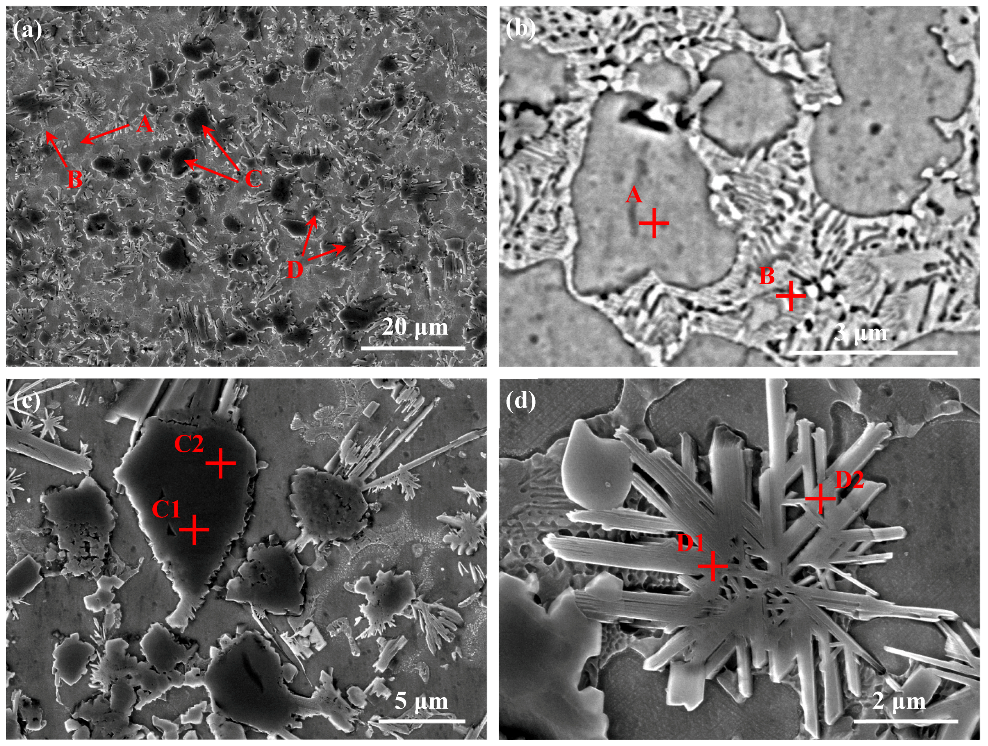
The microstructure morphologies of the middle region in the coating of sample 0 are illustrated in Figure 5. It can be observed from Figure 5a–d that large amounts of bulk-like phases (point C) and flower-like phases (point D) are uniformly distributed in the matrix that mainly consists of cellular grains (point A) and lamellar eutectics (point B) between the cellular grains. The EDS analysis results of the phases are listed in Table 3. The chemical compositions of these areas measured by EDS reveal that the cellular grains (point A) are composed of Ni, Cr, Fe, and C. Combined with the XRD result illustrated in Figure 3, it can be confirmed that the cellular grains are γ-Ni solid solution. Similarly, the lamellar eutectics (point B) contain not only Ni, Cr, and C but also a small amount of B, and can be confirmed as γ-Ni + Ni4B3 eutectics [26]. The bulk-like phases (point C) mainly include Ti, C, and N, and can be identified as Ti(C,N), which incorporates the advantages and characteristics of both TiC and TiN [17,18]. The flower-like phases (point D) mainly consist of Cr, C, and B, which can be confirmed that the chemical compounds of the flower-like phases are Cr7C3 and Cr2B.
The scanning results of elements distribution of the coating of sample 0 are presented in Figure 6. This figure further indicates that the coating matrix mainly consists of γ-Ni solid solution, and the bulk-like phases (A and B) with different size are dispersed in the Ni matrix. For the small bulk-like phase (A), Ti, C, and N are evenly distributed in the whole particle, which is confirmed as Ti(C,N). For the large bulk-like phase (B), the core mainly consists of Ti and N, and is confirmed as residual TiN; moreover, Ti, C, and N are detected synchronously in the shell, which is identified as Ti(C,N). It is interesting that Ti(C,N) tends to grow on the surface of the TiN, and form the typical core-shell structure.
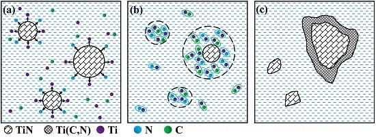
To explain the formation mechanism of the Ti(C,N) phase, a simplified diagram is presented in Figure 7. Under the irradiation of the laser beam, the Ni60 alloy powders with the lowest melting point (1027 °C) melt first, forming the initial molten pool, and with the temperature of the molten pool rising, TiN is decomposed into Ti and N atoms [20] (Figure 7a). Because the temperature of the molten pool is uneven, it is likely that some TiN completely melt, while others partly dissolve [27]. The dissolved atoms are evenly distributed in the laser molten pool due to the stirring action of the convection, and then TiC is formed in-situ with the regeneration of TiN (Figure 7b). According to the heterogeneous nucleation theory [17], the crystal nuclei tend to attach themselves on the already existing phases to reduce the growth energy. In this case, TiC and TiN will precipitate on the undissolved TiN and form the large Ti(C,N) particle [28], which is typical of the core-shell structure. Meanwhile, partial TiN and TiC probably nucleate independently and grow up due to the non-even constituent and heat distribution in the molten pool, as a result, the small Ti(C,N) particle is formed [20] (Figure 7c).
3.2.2. Influence of CeO2 Nanoparticles on the Microstructure of Coatings
The SEM micrographs of the microstructures of the cladding coatings having different CeO2 contents are illustrated in Figure 8a–d, respectively. It can be observed from Figure 8 that there are large amounts of characteristic particles as the reinforcement phases, which distribute randomly and uniformly in the matrix of the coatings. To clearly reveal the chemical compositions of these different reinforcement phases, EDS is used to identify the chemical compositions of the characteristic particles A–I shown in Figure 8. The EDS analysis results are listed in Table 4.
It can be seen from Figure 8a that there are large amounts of dark bulk-like precipitates (A) and grey flower-like phases (B) uniformly distributed in the coating of sample 0. It is known from the EDS results listed in Table 4 that the bulk-like precipitates (point A) are composed of Ti, C and N, and can be confirmed as Ti(C,N). Similarly, the flower-like phases (point B) mainly contain Cr, C and B elements, which can be identified as Cr7C3 and Cr2B.
As shown in Figure 8b, the coating of sample 1 is mainly dominated by three phases: bulk-like phase (C), granular phase (D) and whisker-like phase (E). According to the EDS results listed in Table 4, it can be confirmed that the bulk-like phases and granular phases are Ti(C,N), and the whisker-like phases are Cr7C3 and Cr2B. Obviously, the Ti(C,N) phase in the coating of sample 1 is finer and more compact than that in the coating of sample 0. Previous investigates indicated CeO2 nanoparticles could reduce the critical nucleation radius and increase the number of crystal nucleus, as a result, the agglomeration and the growth of Ti(C,N) phase were distinctly suppressed [21,22,23]. In addition, CeO2 nanoparticles could also cause the lattice distortion of some grains in the coating due to the lager atomic radius, and distributed on the grain boundary to equalize the energy of distortion, which could also restrain the growth of Ti(C,N) phase [21,22].
The SEM images (Figure 8c,d) show that the microstructures of the coatings of sample 2 and sample 3 are similar to that of the coating of sample 1, and the Ti(C,N) and Cr7C3/Cr2B are confirmed on the basis of their chemical compositions in Table 4. It is found that the more CeO2 additive is added, the coarser the Ti(C,N) phase is. Similar conclusions were reported by Wang et al. [22] and Sharma et al. [29], namely, the microstructures and properties of the Ni-based coatings decreased when the additive of CeO2 was higher than 1 wt %. The worse grain refinement of 2 wt % CeO2 and 3 wt % CeO2 may be attributed to the agglomeration of CeO2 nanoparticles. Because of the surface effect, nanoparticles are easy to reunite [22,30]. In this case, CeO2 nanoparticles are not well-distributed in the molten pool, which reduces the grain refining effect.
The back-scattered electron micrograph and the corresponding EDS results of certain phases in the coating of sample 2 are shown in Figure 9, which is typical for the coatings modified with CeO2 nanoparticles. It is noted that a kind of white core-black shell structure appears in the coating (Figure 9a). EDS results indicate that the white core (point 1) contains a large amount of Ce and O, which can be confirmed as CeO2. The black shell (point 2) contains a high concentration of Ti, C, and N, which can be confirmed as Ti(C,N). In addition, there are B, C, Cr, Ti, and Ni in whisker phase (point 3), whose growth is restrained by the CeO2-centered core-shell structure. Combined with XRD results shown in Figure 3, it can be confirmed that whisker phase is Cr2B and Cr7C3. According to the heterogeneous nucleation theory [17], the in-situ synthesized Ti(C,N) tends to nucleate on the surface of CeO2 nanoparticles to reduce the growth energy, and consequently the core-shell structure is formed. In this case, the CeO2 particles are fixed in the matrix and then the growth of other phases around the core-shell structure is retarded.
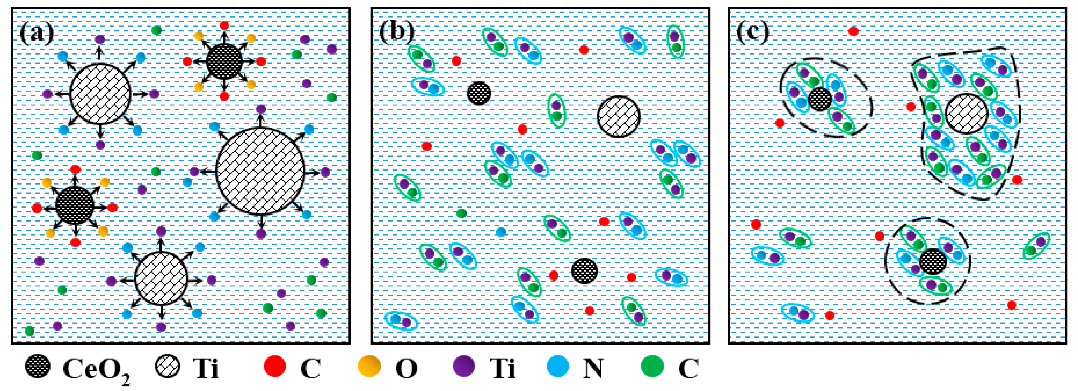
To interpret the refinement mechanism of CeO2 nanoparticles, a simplified diagram is presented in Figure 10. As shown in Figure 10a, partial CeO2 decomposes into Ce and O atoms, meanwhile, ex-situ TiN dissolves into the molten pool. The dissolved O atoms can react with B and Si from the Ni60 powders, and produce low-density oxidation resultants that will float on the surface of the molten pool. It is likely that some TiN and CeO2 nanoparticles completely melt, while others partly dissolve. The dissolved atoms are evenly distributed in the molten pool due to the stirring action of the convection, and then TiC and TiN are formed in-situ (Figure 10b). Finally, unmelted CeO2 nanoparticles become heterogeneous nuclei, and the newly generated TiC and TiN tend to precipitate on the residual CeO2 nanoparticles and form the core-shell structure, which can greatly increase the nucleation rate and improve the precipitation of Ti(C,N). Meanwhile, the undissolved TiN can also act as the nucleation site for the TiC and TiN in the molten pool, and form the large Ti(C,N) particle. In addition, the decomposed Ce atoms will enrich on the grain boundary and further suppress the growth of Ti(C,N) (Figure 10c).
3.3. Micro-Hardness and Wear Resistance of the Coatings
The micro-hardness distributions along the depth direction of the composite coatings are shown in Figure 11. Generally, the coatings of different samples have a similar micro-hardness distribution, and the micro-hardness distributions have a clear downtrend along the cladding coating surface to the substrate. Due to the combined action of solution strengthening and second-phase strengthening, the average hardness of the coating of sample 0 is enhanced by 2.8 times compared to that of the Ti6Al4V substrate (336.8 HV0.2). In contrast, the average hardness of the coating of sample 1 is apparently higher than that of sample 0, which is related to the refining effect of CeO2 nanoparticles on the Ti(C,N) reinforcement phases. However, according to the analysis in above section, too much CeO2 (2 wt % and 3 wt %) reduces the refining effect of CeO2 nanoparticles on the Ti(C,N) phases. Thus, the average hardness of the coating of sample 2 is lower than that of the coating of sample 1, and with the increase of CeO2 additive in the pre-placed powders, the average hardness of coating further decreases.
The wear test results of the Ti6Al4V substrate and the coatings are plotted in Figure 12, which shows that all the wear volume losses approximately have a linear relationship with the wear time. It can be seen that the cladding coatings have much better wear resistance than the Ti6Al4V titanium alloy substrate. For the Ti6Al4V substrate, the coatings of samples 0, 1, 2, and 3, the total wear volume losses are 1008.5 × 10−2 mm3, 90.2 × 10⁻² mm3, 41.6 × 10⁻² mm3, 51.7 × 10⁻² mm3, and 55.6 × 10⁻² mm3, respectively. In comparison with the Ti6Al4V substrate, the wear resistances of the coatings of sample 0, 1, 2, and 3 are respectively increased by 11.2, 24.3, 19.5, and 18.1 times, which indicates that the coatings modified by CeO2 nanoparticles additive have higher wear resistance than the coating fabricated by pre-placed powders without CeO2 nanoparticles addition. Generally, the wear resistance of the coatings is proportional to its hardness. In the paper, the wear resistance of the coatings with different content of CeO2 additive on the changed trend is similar to the average micro-hardness of that. Among all the coatings, the coating modified with 1 wt % CeO2 additive presents the best wear resistance, which is highly related to the highest micro-hardness. Meanwhile, as mentioned earlier, the microstructure in the coating of sample 1 is finer and more compact than that in the coating of other samples due to the crystalline grain-refinement effect of the CeO2 additive, which is also the important reason for the high wear resistance of sample 1. However, according to relevant reports [31,32], the crystalline grain-refinement effect might be related to the content of rare earth oxide, and excessive rare earth oxide would reduce the function of refinement. As a result, as the content of CeO2 additive further increases, the wear resistance of coatings of sample 2 and 3 decreases. Therefore, only an appropriate amount of CeO2 additive in the pre-placed powders can enhance the coating performance.
The wear morphologies of the Ti6Al4V substrate and the cladding coatings present different characteristics, as shown in Figure 13. It is observed from Figure 13a that there are deep grooves and adhesive features on the wear surface of the Ti6Al4V substrate. During the process of dry sliding friction, it is easy for the hard asperities on the grinding ball to penetrate into the surface of relative soft titanium substrate, forming micro-cutting and deep grooves on the worn surface [33]. Meanwhile, the formation of debris particles in the frictional area were promoted due to abrasion generated by a hard ceramic counterbody, meaning that wear particles trapped in the contact zone induce the third body effect, which further results in the increase of the total wear of the surface [34]. In contrast, no obvious characteristic of micro-cutting or ploughing grooves are found on the worn surfaces of the coatings due to the high hardness of the coatings. Among all the coatings, the coating of sample 1 presents the smoothest worn surface; the coating of sample 2 has the second smoothest worn surface; and the coating of sample 0 exhibits the roughest worn surface, which is highly related to the micro-hardness. Moreover, spalling features are detected on the worn surfaces of the coatings due to the alternating stress from the grinding ball (Figure 13b–e). As mentioned above, the addition of CeO2 can effectively refine the grains, thus the toughness of the coatings can also be improved. In this case, the most obvious spalling characteristic is presented in the coating of sample 0 because of the poor toughness (Figure 13b). Whereas, the coating of sample 1 with best toughness shows the least obvious spalling characteristic (Figure 13c).
The SEM images of the wear debris of titanium alloy substrate and cladding coatings sliding against Si3N4 balls are shown in Figure 14, and the EDS results of the wear debris are illustrated in Figure 15. It can be seen that the wear debris from titanium alloy substrate coupled with the Si3N4 ceramic ball is plate-like and has a maximum width of approximately 30 µm and length of approximately 70 µm, which further reveals that titanium alloy substrate suffers from severe cutting and adhesion. The result of EDS analysis (Figure 15a) shows that the wear debris from titanium alloy substrate contains a large amount of Ti and O, and a small amount of Al and V, which indicates the existence of oxidation wear. During the dry sliding friction, a large amount of heat is produced and accumulated on the friction surface, so the temperature becomes higher and higher, leading to oxidation wear. However, the wear debris from cladding coatings is granular and has a much smaller size than the wear debris from the titanium alloy substrate, which shows that the cladding coatings experience minor cutting during the dry sliding friction. Meanwhile, the coating of sample 1 has the smallest wear debris size, and the coating of sample 2 exhibits the second-smallest wear debris size, while the coating of sample 0 shows the biggest wear debris size, which is highly related to the wear resistance of the coatings. According to the EDS analysis results (Figure 15b–e), the wear debris of cladding coatings contains a high concentration of O, which indicates that the coatings suffer from the oxidation wear during the friction tests.
In summary, the wear mechanisms of titanium alloy substrate include ploughing, adhesive features, and oxidation wear, while the wear mechanisms of high-hardness cladding coatings include slight ploughing, spalling features, and oxidation wear. The influence of CeO2 nanoparticles on the wear properties of the coatings is obvious, namely, the coatings fabricated by the pre-placed powders with CeO2 nanoparticles have higher hardness, lower wear loss, and better wear morphology compared with coating fabricated by the pre-placed powders without CeO2 nanoparticles. What is more, the coating fabricated by the pre-placed powders with 1 wt % CeO2 exhibits better wear resistance than the coating fabricated by the pre-placed powders with 2 wt % or 3 wt % CeO2 additive, which indicates that the amount of CeO2 additive in the pre-placed powders should be controlled to a certain extent.
4. Conclusions
- In-situ synthesized Ti(C,N) reinforced Ni-based composite coatings are fabricated on Ti6Al4V substrates by laser cladding using Ni60 alloy, C, TiN, and nano-CeO2 powders as the pre-placed materials. The composite coatings metallurgically bonded with the substrates are mainly composed of γ-Ni, Ni3Ti, Ni4B3, Ti(C,N), TiC, TiN, Cr2B, and Cr7C3 phases.
- The formation mechanisms of Ti(C,N) particles as reinforced phases in the coating are that the large Ti(C,N) particles form around TiN particles, and the small Ti(C,N) particles form by independent nucleation.
- The microstructures of the coatings fabricated by pre-placed powders with different contents of CeO2 additive are obviously improved, which is mainly related to the heterogeneous nucleation of CeO2 nanoparticles.
Due to the comprehensive action of second-phase strengthening and solution strengthening, the wear resistance of the coating fabricated by the pre-placed powders without CeO2 additive is 11.2 times higher than that of the substrate. With the additives of CeO2 nanoparticles in the pre-powders, the wear resistance of the coatings is further increased because of fine-grain strengthening, and 1 wt % content of CeO2 nanoparticles in the pre-powders is the optimal choice for improving the wear resistance of the coatings.
Author Contributions
T.C., F.W. and D.L. conceived and designed the experiments; T.C and F.W. performed the experiments; T.C., F.W. and H.W. analyzed the data and discussed the experiment; T.C., F.W. and D.L. prepared the paper. The manuscript was reviewed by all authors.
Funding
This research was funded by the National Natural Science Foundation of China (Grant 51775559).
Conflicts of Interest
The authors declare no conflict of interest.
References
- Veiga, C.; Davim, J.P.; Loureiro, A.J.R. Properties and applications of titanium alloys: A brief review. Rev. Adv. Mater. Sci. 2012, 32, 133–148. [Google Scholar]
- Peters, M.; Kumpfert, J.; Ward, C.H.; Leyens, C. Titanium Alloys for Aerospace Applications. Adv. Eng. Mater. 2003, 5, 419–427. [Google Scholar] [CrossRef]
- Sachdev, A.K.; Kulkarni, K.; Fang, Z.Z.; Yang, R.; Girshov, V. Titanium for Automotive Applications: Challenges and Opportunities in Materials and Processing. JOM 2012, 64, 553–565. [Google Scholar] [CrossRef]
- Budinski, K.G. Tribological properties of titanium alloys. Wear 1991, 151, 203–217. [Google Scholar] [CrossRef]
- Mao, Y.S.; Wang, L.; Chen, K.M.; Wang, S.Q.; Cui, X.H. Tribo-layer and its role in dry sliding wear of Ti-6Al-4V alloy. Wear 2013, 297, 1032–1039. [Google Scholar] [CrossRef]
- Lin, Y.H.; Yao, J.H.; Lei, Y.P.; Fu, H.G.; Wang, L. Microstructure and properties of TiB2-TiB reinforced titanium matrix composite coating by laser cladding. Opt. Laser. Eng. 2016, 86, 216–227. [Google Scholar] [CrossRef]
- Candel, J.J.; Amigó, V.; Ramos, J.A.; Busquets, D. Sliding wear resistance of TiCp reinforced titanium composite coating produced by laser cladding. Surf. Coat. Technol. 2010, 204, 3161–6166. [Google Scholar] [CrossRef]
- Li, J.N.; Chen, C.Z.; Squartini, T.; He, Q.S. A study on wear resistance and microcrack of the Ti3Al/TiAl+TiC ceramic layer deposited by laser cladding on Ti-6Al-4V alloy. Appl. Surf. Sci. 2010, 257, 1550–1555. [Google Scholar] [CrossRef]
- Wang, F.; Chen, C.Z.; Yu, H.J. Research status of laser cladding on titanium and its alloys: A review. Mater. Des. 2014, 58, 412–425. [Google Scholar] [CrossRef]
- Chao, M.J.; Wang, W.L.; Liang, E.J.; Ouyang, D.X. Microstructure and wear resistance of TaC reinforced Ni-based coating by laser cladding. Surf. Coat. Technol. 2008, 202, 1918–1922. [Google Scholar] [CrossRef]
- Shi, C.; Lei, J.B.; Zhou, S.F.; Dai, X.Q.; Zhang, L.C. Microstructure and mechanical properties of carbon fibers strengthened Ni-based coatings by laser cladding: The effect of of carbon fiber contents. J. Alloy. Compd. 2018, 744, 146–155. [Google Scholar] [CrossRef]
- Dong, G.; Yan, B.; Deng, Q.L.; Yu, T. Microstructure and Wear Resistance of in situ NbC Particles Reinforced Ni-based Alloy Composite Coating by Laser Cladding. J. Wuhan Univ. Technol. 2012, 27, 231–237. [Google Scholar] [CrossRef]
- Li, J.; Zhang, X.J.; Wang, H.P.; Li, M.P. Microstructure and mechanical properties of Ni-based composite coatings reinforced by in situ synthesized TiB2+TiC by laser cladding. Int. J. Min. Met. Mater. 2013, 20, 57–64. [Google Scholar] [CrossRef]
- Fernández, M.R.; García, A.; Cuetos, J.M.; González, R.; Noriega, A.; Cadenas, M. Effect of actual WC content on the reciprocating wear of a laser cladding NiCrBSi alloy reinforced with WC. Wear 2014, 324–325, 80–89. [Google Scholar] [CrossRef]
- Sun, R.L.; Lei, Y.W.; Niu, W. Laser clad TiC reinforced NiCrBSi composite coatings on Ti–6Al–4V alloy using a CW CO2 laser. Surf. Coat. Technol. 2009, 203, 1395–1399. [Google Scholar] [CrossRef]
- Forn, A.; Picas, J.A.; Fuentes, G.G.; Elizalde, E. Mechanical and tribological properties of TiCxN1−x, wear resistant coatings. Int. J. Refract. Met. Hard Mater. 2001, 19, 507–513. [Google Scholar] [CrossRef]
- Li, J.N.; Chen, C.Z.; Zhang, C.F. Effect of nano-CeO2 on microstructure properties of TiC/TiN+nTiCN reinforced composite coating. Bull. Mater. Sci. 2013, 36, 399–404. [Google Scholar]
- Yang, Y.L.; Zhang, D.; Yan, W.; Zheng, Y.R. Microstructure and wear properties of TiCN/Ti coatings on titanium alloy by laser cladding. Opt. Laser. Eng. 2010, 48, 119–124. [Google Scholar] [CrossRef]
- Peng, Y.; Miao, H.; Peng, Z. Development of TiCN-based cermets: Mechanical properties and wear mechanism. Int. J. Refract. Met. Hard Mater. 2013, 39, 78–89. [Google Scholar] [CrossRef]
- Qi, Y.T.; Cao, Z.X.; Sheng, L.Y.; Cao, R.P. Microstructure of Fe-Based Alloy Composite Coatings Reinforced by Ti(C0.3N0.7) Particles through Laser Cladding Technology. J. Iron Steel Res. Int. 2013, 20, 78–82. [Google Scholar] [CrossRef]
- Li, J.N.; Chen, C.Z.; Wang, D.G.; Li, W. Microstructures and wear properties of YPSZ/CeO2 reinforced composites deposited by laser cladding. Compos. Part B Eng. 2012, 43, 896–901. [Google Scholar] [CrossRef]
- Wang, K.L.; Zhang, Q.B.; Sun, M.L.; Wei, X.G.; Zhu, Y.M. Rare earth elements modification of laser-clad nickel-based alloy coatings. Appl. Surf. Sci. 2001, 174, 191–200. [Google Scholar] [CrossRef]
- Zhang, S.H.; Li, M.X.; Tong, Y.C.; Yoon, J.H.; Lee, C.G.; He, Y.Z. Laser clad Ni-base alloy added nano- and micron-size CeO2 composites. Opt. Laser Technol. 2008, 40, 716–722. [Google Scholar] [CrossRef]
- Li, J.; G, S.; W, X.; Suo, H. Physical and surface performance of laser clad Ni based coating on a TA15-2 alloy. Chin. J. Laser. 2013, 40, 1103008. [Google Scholar]
- Qi, Y.; Wang, W. Formation mechanism of in-situ Ti(C0.3N0.7) reinforced phase through laser cladding technology. Appl. Laser 2016, 36, 511–515. [Google Scholar]
- Yu, T.; Deng, Q.L.; Gang, D.; Yang, J.G. Effects of Ta on microstructure and microhardness of Ni based laser clad coating. Appl. Surf. Sci. 2011, 257, 5098–5103. [Google Scholar] [CrossRef]
- Weng, F.; Yu, H.; Chen, C.Z.; Liu, J.N.; Zhao, L.J. Microstructures and properties of TiN reinforced Co-based composite coatings modified with Y2O3 by laser cladding on Ti-6Al-4V alloy. J. Alloy. Compd. 2015, 650, 178–184. [Google Scholar] [CrossRef]
- Liu, N.; Yin, W.H.; Zhu, L.W. Effect of TiC/TiN powder size on microstructure and properties of Ti(C,N)-based cermets. Mat. Sci. Eng. A 2007, 445–446, 707–716. [Google Scholar] [CrossRef]
- Sharma, S.P.; Dwivedi, D.K.; Jain, P.K. Effect of CeO2 addition on the microstructure, hardness and abrasive wear behavior of flame sprayed Ni-based coatings. Proc. Inst. Mech. Eng. J. 2008, 222, 8925–8933. [Google Scholar]
- Li, M.X.; He, Y.Z.; Yuan, X.M. Effect of nano-Y2O3 on microstructure of laser cladding cobalt-based alloy coatings. Appl. Surf. Sci. 2006, 252, 2882–2887. [Google Scholar]
- Cheng, X.Y.; Feng, Y.S.; He, J. Influence of CeO2 on Microstructure and microhardness of TiC4 coating Produced by Laser-Cladding. Mater. Mech. Eng. 2010, 34, 20–23. [Google Scholar]
- Cai, Y.C.; Luo, Z.; Chen, Y.; Ao, S.S. Influence of CeO2 on tribological behaviour of TiC/ Fe-based composite coating. Surf. Eng. 2017, 33, 1–8. [Google Scholar] [CrossRef]
- Bai, L.L.; Li, J.; Chen, J.L.; Song, R.; Shao, J.Z.; Qu, C.C. Effect of the content of B4C on microstructural evolution and wear behaviors of the laser-clad coatings fabricated on Ti6Al4V. Opt. Laser Technol. 2016, 76, 33–45. [Google Scholar] [CrossRef]
- Landolt, D.; Mischler, S.; Stemp, M.; Barril, S. Third body effects and material fluxes in tribocorrosion systems involving a sliding contact. Wear 2004, 256, 517–524. [Google Scholar] [CrossRef]
Figure 1.
SEM images of the powders used in the present study for laser cladding (a) Ni60 (b) graphite (c) TiN (d) CeO2.
Figure 1.
SEM images of the powders used in the present study for laser cladding (a) Ni60 (b) graphite (c) TiN (d) CeO2.

Figure 2.
Schematic illustration of the laser-cladding system.
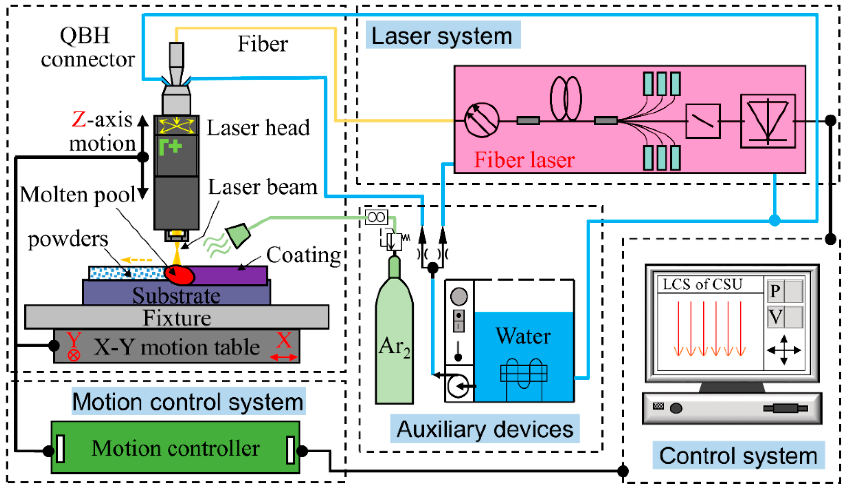
Figure 3.
XRD analysis results of the coatings fabricated by pre-placed powders with different CeO2 contents.
Figure 3.
XRD analysis results of the coatings fabricated by pre-placed powders with different CeO2 contents.
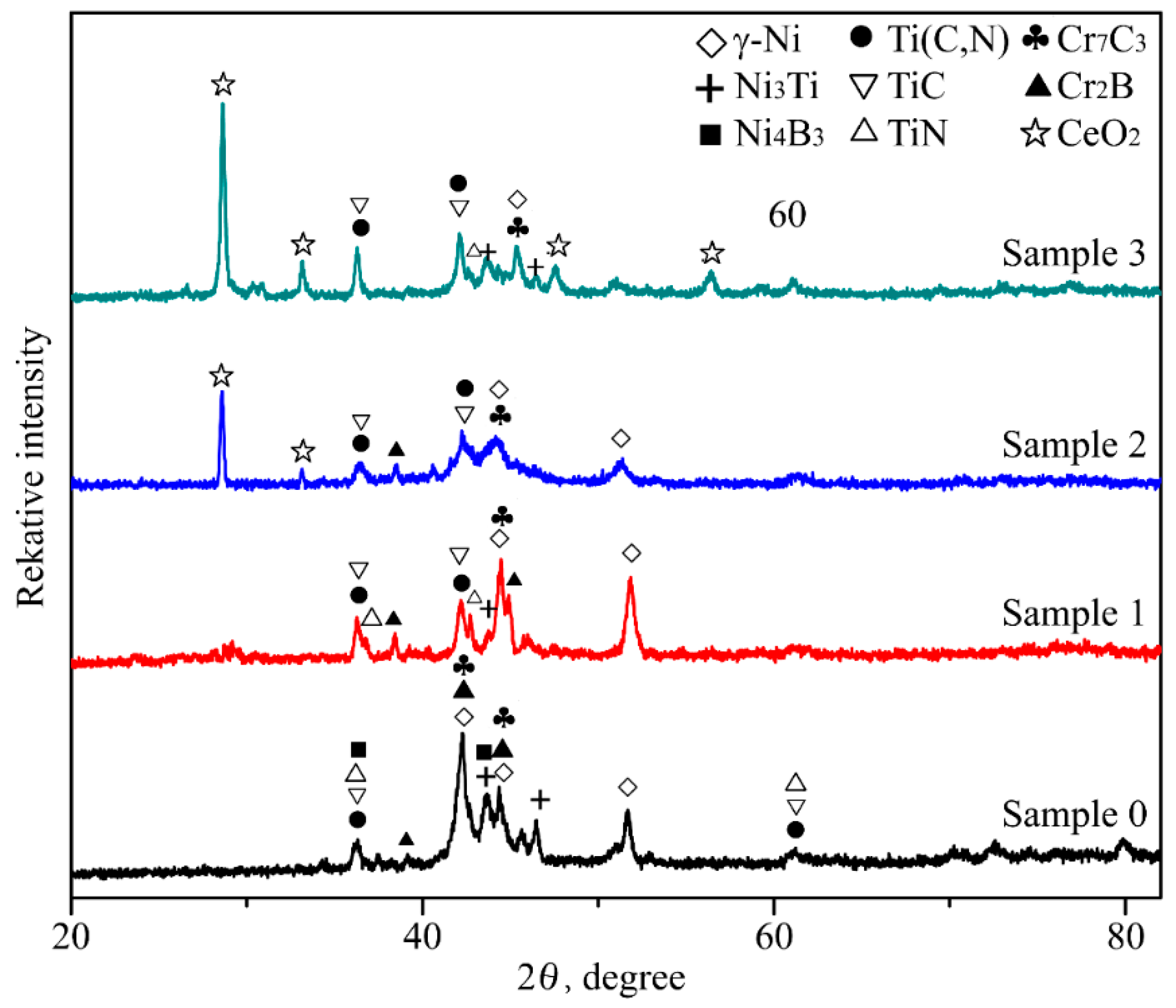
Figure 4.
(a) Cross-section morphologies and chemical composition distribution of the coating without CeO2 additive by EDS line scanning; (b) detail view of the bonding regions between the coating and the substrate.
Figure 4.
(a) Cross-section morphologies and chemical composition distribution of the coating without CeO2 additive by EDS line scanning; (b) detail view of the bonding regions between the coating and the substrate.
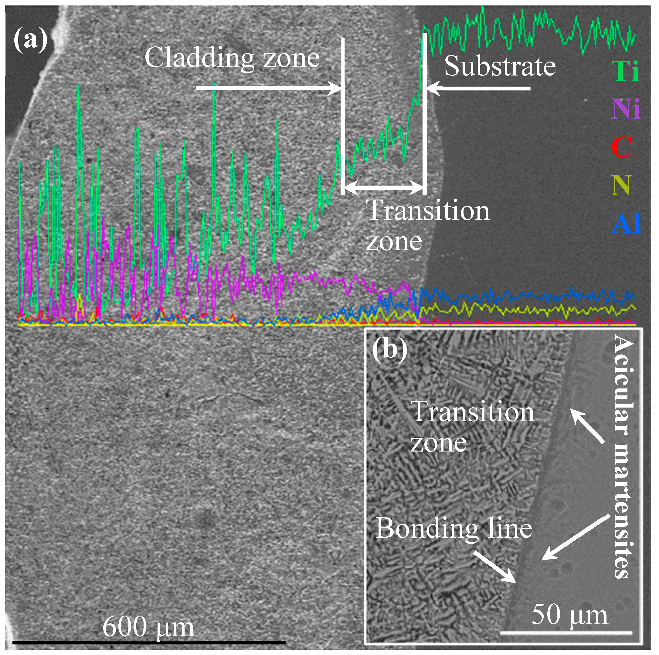
Figure 5.
SEM images of the coating without CeO2 additive: (a) the middle region; (b) the cellular grain and lamellar eutectic; (c) the bulk-like phase; (d) the flower-like phase.
Figure 5.
SEM images of the coating without CeO2 additive: (a) the middle region; (b) the cellular grain and lamellar eutectic; (c) the bulk-like phase; (d) the flower-like phase.

Figure 6.
Results of element distribution analysis by EDS surface scanning of the coating without CeO2 additive.
Figure 6.
Results of element distribution analysis by EDS surface scanning of the coating without CeO2 additive.
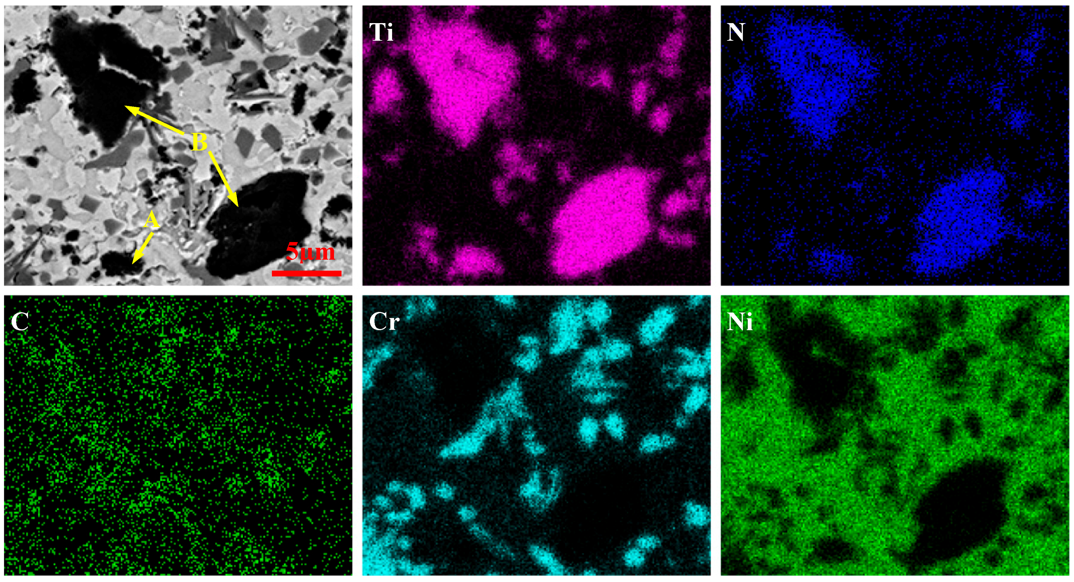
Figure 7.
The diagram illustration for the formation mechanism of Ti(C,N): (a) dissolution of TiN; (b) the generation of TiC and TiN; (c) the formation of Ti(C,N).
Figure 7.
The diagram illustration for the formation mechanism of Ti(C,N): (a) dissolution of TiN; (b) the generation of TiC and TiN; (c) the formation of Ti(C,N).

Figure 8.
SEM images of the coatings fabricated by pre-placed powders with different CeO2 contents: (a) 0 wt % CeO2; (b) 1 wt % CeO2; (c) 2 wt % CeO2, and (d) 3 wt % CeO2.
Figure 8.
SEM images of the coatings fabricated by pre-placed powders with different CeO2 contents: (a) 0 wt % CeO2; (b) 1 wt % CeO2; (c) 2 wt % CeO2, and (d) 3 wt % CeO2.
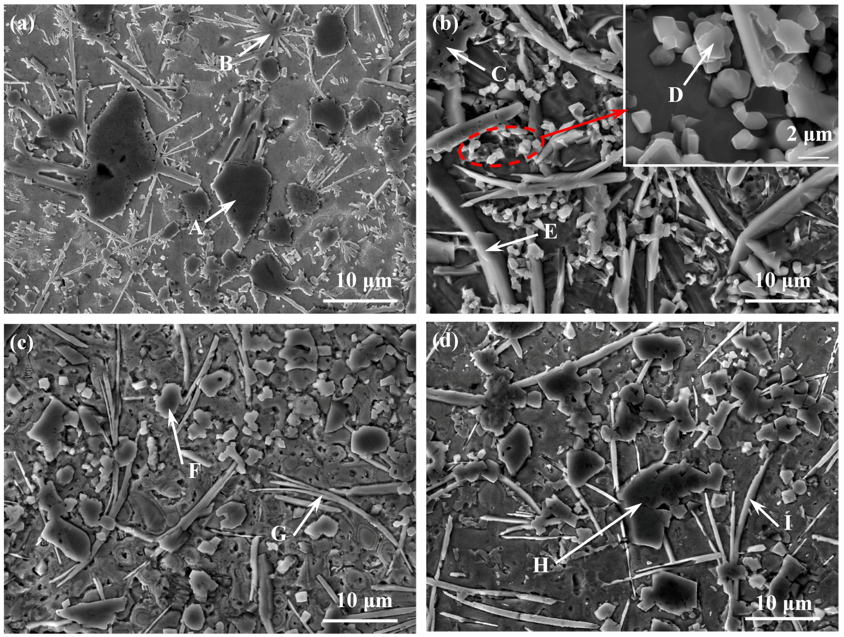
Figure 9.
(a) back-scattered electron micrograph in the coating of sample 2; (b) the corresponding EDS analysis results for point 1, (c) point 2 and (d) point 3.
Figure 9.
(a) back-scattered electron micrograph in the coating of sample 2; (b) the corresponding EDS analysis results for point 1, (c) point 2 and (d) point 3.
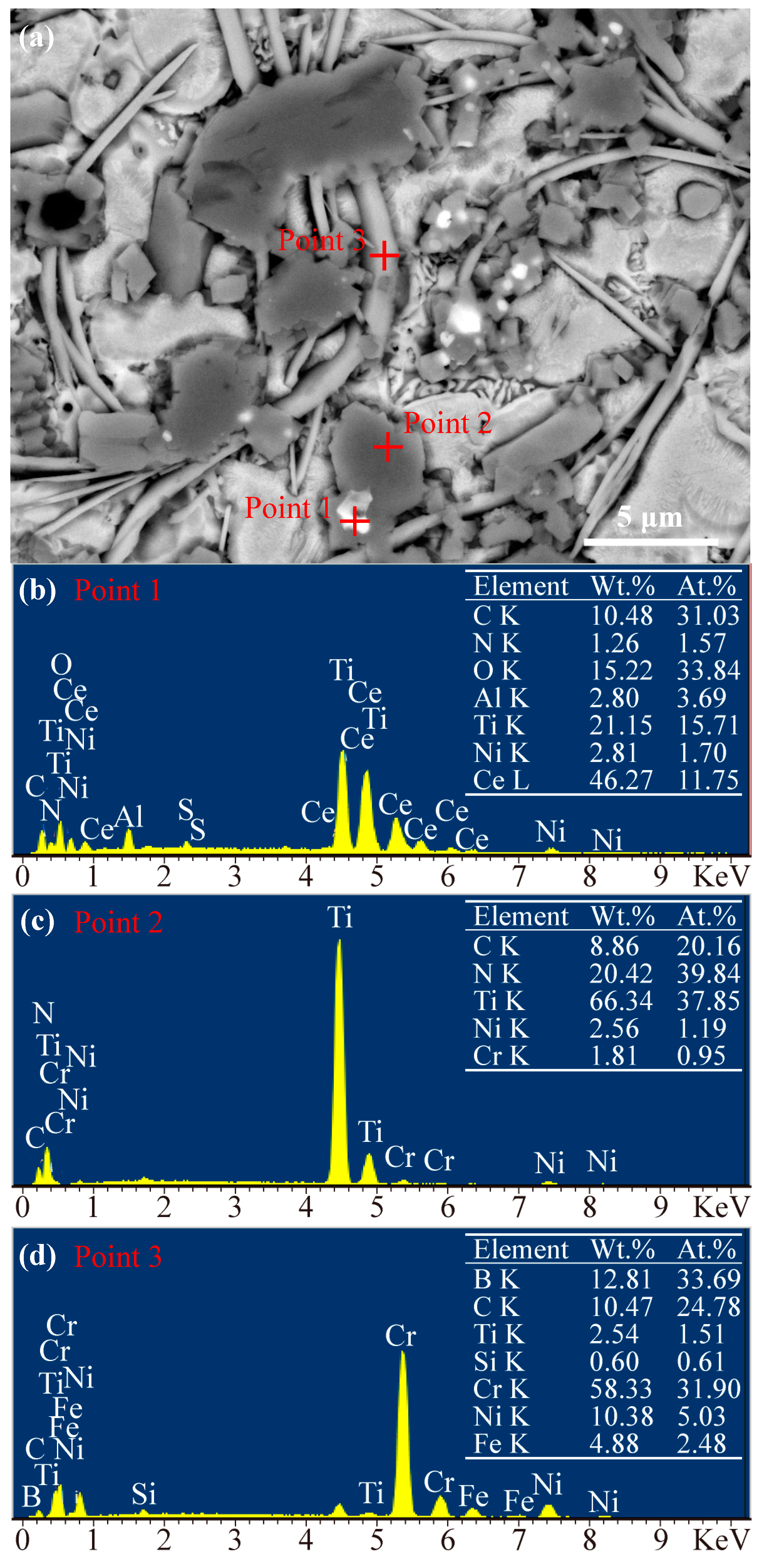
Figure 10.
Illustration of the CeO2 mechanism: (a) dissolution of TiN and CeO2; (b) the formation of TiC and TiN; (c) the grain refinement of CeO2.
Figure 10.
Illustration of the CeO2 mechanism: (a) dissolution of TiN and CeO2; (b) the formation of TiC and TiN; (c) the grain refinement of CeO2.

Figure 11.
Micro-hardness profiles along the depth direction of the cladding coatings.
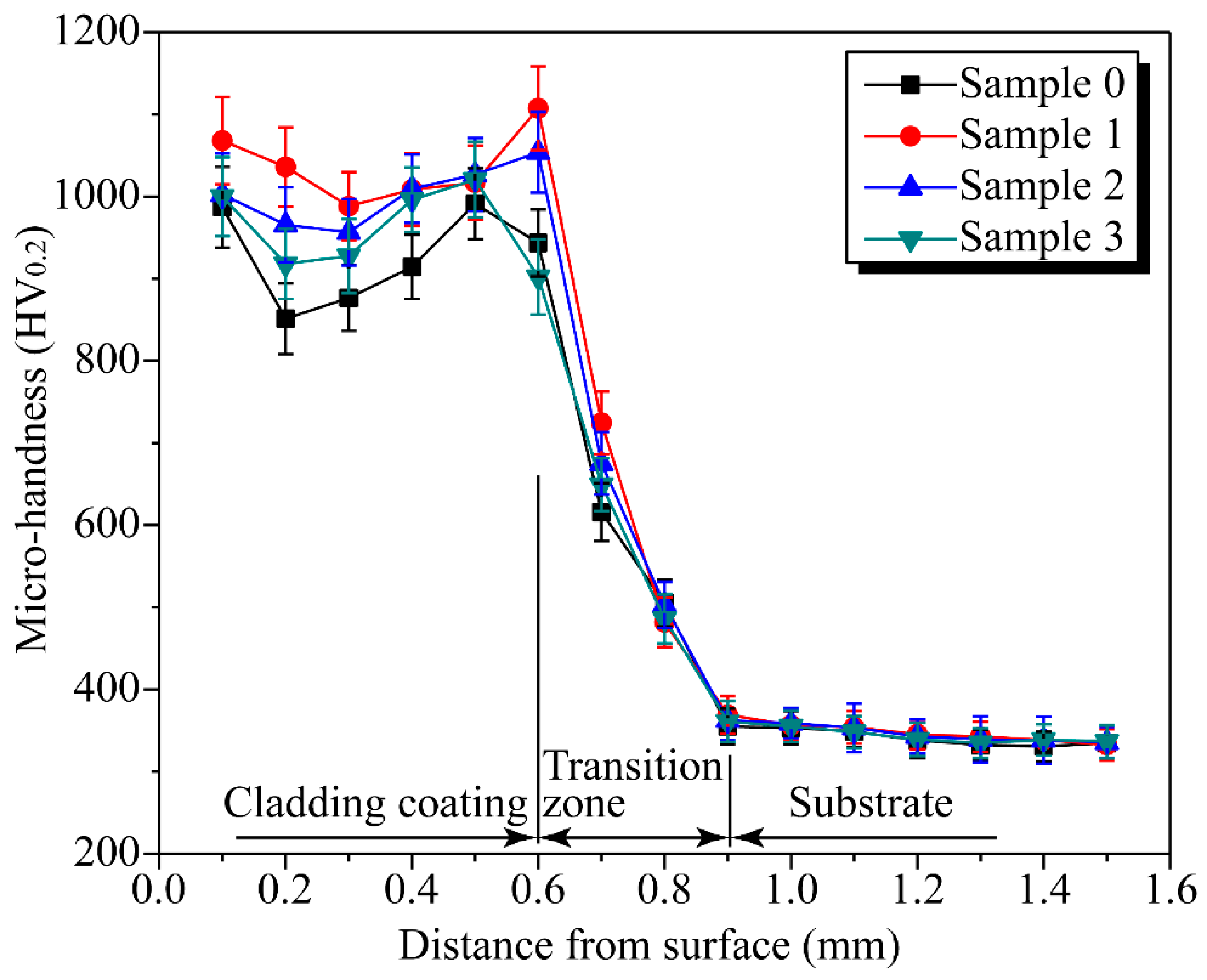
Figure 12.
Wear volume loss of the substrate and the coatings versus wear time.

Figure 13.
Worn surface SEM images of titanium substrate or the coatings fabricated by pre-placed powders with different CeO2 contents: (a) titanium substrate; (b) 0 wt % CeO2; (c) 1 wt % CeO2; (d) 2 wt % CeO2, and (e) 3 wt % CeO2.
Figure 13.
Worn surface SEM images of titanium substrate or the coatings fabricated by pre-placed powders with different CeO2 contents: (a) titanium substrate; (b) 0 wt % CeO2; (c) 1 wt % CeO2; (d) 2 wt % CeO2, and (e) 3 wt % CeO2.

Figure 14.
SEM images of wear debris of (a) substrate, (b) sample 0, (c) sample 1, (d) sample 2, and (e) sample 3.
Figure 14.
SEM images of wear debris of (a) substrate, (b) sample 0, (c) sample 1, (d) sample 2, and (e) sample 3.
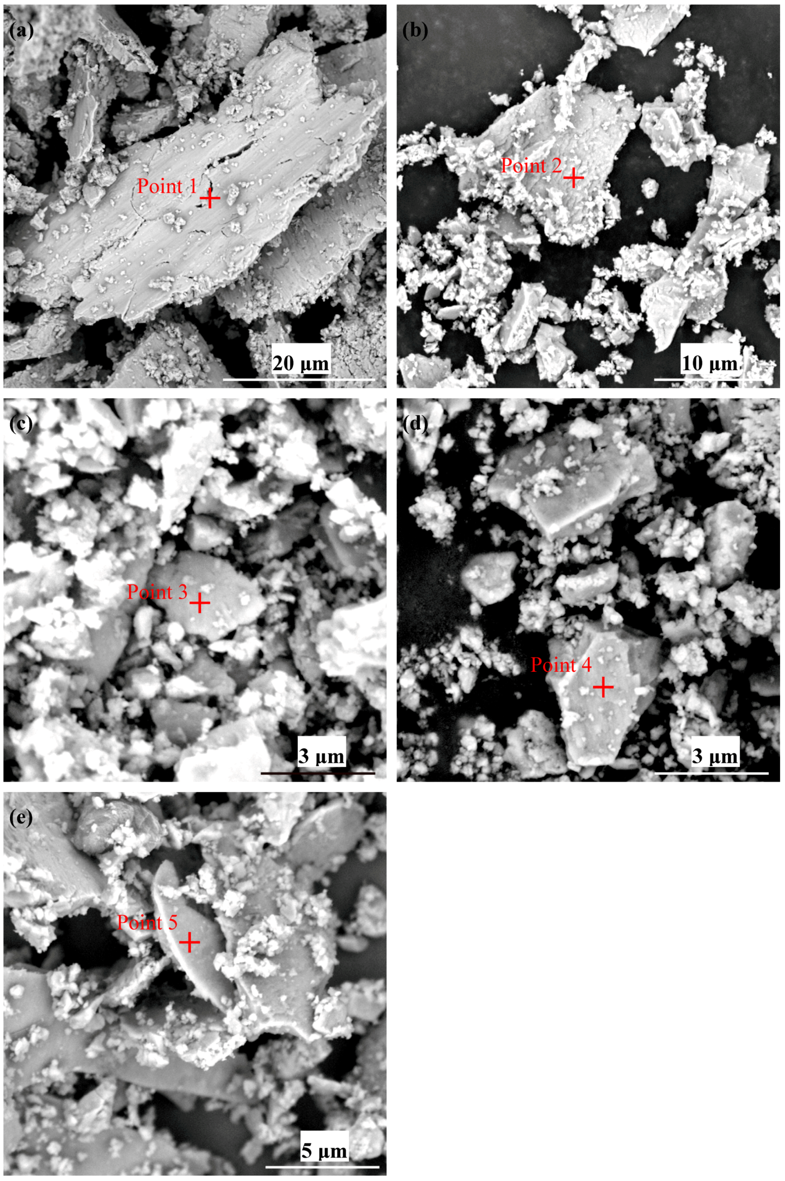
Figure 15.
EDS results of wear debris in Figure 14: (a) point 1; (b) point 2; (c) point 3; (d) point 4; (e) point 5.
Figure 15.
EDS results of wear debris in Figure 14: (a) point 1; (b) point 2; (c) point 3; (d) point 4; (e) point 5.


Table 1.
The chemical composition (in wt %) of the Ni60 self-fluxing alloy powder.
| Cr | Fe | W | Si | B | C | Ni |
|---|---|---|---|---|---|---|
| 15.5 | 15 | 3 | 4 | 3.5 | 0.65 | Bal. |
Table 2.
The ingredients of the pre-placed powders.
| Sample Group No. | Powder Ingredients (wt %) | |||
|---|---|---|---|---|
| Ni60 | C | TiN | CeO2 | |
| Sample 0 | 88 | 2 | 10 | 0 |
| Sample 1 | 87 | 2 | 10 | 1 |
| Sample 2 | 86 | 2 | 10 | 2 |
| Sample 3 | 85 | 2 | 10 | 3 |
Table 3.
EDS analysis results of phases in Figure 5.
Table 3.
EDS analysis results of phases in Figure 5.
| Area | Elements (at %) | ||||||
|---|---|---|---|---|---|---|---|
| Ti | N | C | Cr | B | Ni | Fe | |
| A | 3.02 | - | 12.24 | 8.13 | - | 65.71 | 10.90 |
| B | 3.99 | - | 15.45 | 7.29 | 8.66 | 62.12 | 2.49 |
| C1 | 37.16 | 50.47 | 12.37 | - | - | - | - |
| C2 | 33.82 | 16.14 | 42.95 | 1.48 | - | 5.61 | - |
| D1 | 1.04 | - | 22.54 | 23.18 | 51.13 | 1.85 | 0.26 |
| D2 | 1.84 | - | 37.36 | 16.58 | 23.55 | 17.47 | 3.20 |
Table 4.
The EDS analysis results of phases in Figure 8.
Table 4.
The EDS analysis results of phases in Figure 8.
| Region | Elements (at %) | ||||||
|---|---|---|---|---|---|---|---|
| Ti | N | C | Cr | B | Ni | Fe | |
| A | 37.16 | 50.47 | 12.37 | - | - | - | - |
| B | 1.84 | - | 37.36 | 16.58 | 23.55 | 17.47 | 3.20 |
| C | 29.69 | 52.82 | 14.76 | 0.72 | - | 1.76 | 0.25 |
| D | 43.81 | 8.58 | 42.59 | 3.91 | - | 1.11 | - |
| E | 2.34 | - | 31.33 | 21.61 | 42.54 | 1.22 | 0.96 |
| F | 34.79 | 40.84 | 21.59 | 0.96 | - | 1.82 | - |
| G | 1.51 | - | 24.78 | 31.90 | 33.69 | 5.03 | 2.48 |
| H | 40.48 | 26.34 | 33.18 | - | - | - | - |
| I | 2.70 | - | 25.26 | 17.26 | 42.96 | 8.04 | 3.78 |
© 2018 by the authors. Licensee MDPI, Basel, Switzerland. This article is an open access article distributed under the terms and conditions of the Creative Commons Attribution (CC BY) license (http://creativecommons.org/licenses/by/4.0/).
Share and Cite
MDPI and ACS Style
Chen, T.; Wu, F.; Wang, H.; Liu, D. Laser Cladding In-Situ Ti(C,N) Particles Reinforced Ni-Based Composite Coatings Modified with CeO2 Nanoparticles. Metals 2018, 8, 601. https://doi.org/10.3390/met8080601
AMA Style
Chen T, Wu F, Wang H, Liu D. Laser Cladding In-Situ Ti(C,N) Particles Reinforced Ni-Based Composite Coatings Modified with CeO2 Nanoparticles. Metals. 2018; 8(8):601. https://doi.org/10.3390/met8080601
Chicago/Turabian StyleChen, Tao, Fan Wu, Haojun Wang, and Defu Liu. 2018. "Laser Cladding In-Situ Ti(C,N) Particles Reinforced Ni-Based Composite Coatings Modified with CeO2 Nanoparticles" Metals 8, no. 8: 601. https://doi.org/10.3390/met8080601
Note that from the first issue of 2016, this journal uses article numbers instead of page numbers. See further details here.