Effect of Process Parameters on Deposition Properties of Functionally Graded STS 316/Fe Manufactured by Laser Direct Metal Deposition


1
Joining R&D Group, Korea Institute of Industrial Technology, 156 Gaetbeol-ro(Songdo-dong), Yeonsu-Gu, Incheon 21999, Korea
2
Department of Mechanical Design Engineering, Hanyang University, 222 Wangsimni-ro, Seoul 04763, Korea
*
Author to whom correspondence should be addressed.
Metals 2018, 8(8), 607; https://doi.org/10.3390/met8080607
Submission received: 17 July 2018
/
Revised: 29 July 2018
/
Accepted: 2 August 2018
/
Published: 4 August 2018
(This article belongs to the Special Issue Functionally Graded Materials)
Abstract
:Stainless steel 316 (STS316)/Fe functionally graded materials were fabricated by direct energy deposition (DED) method using laser as a heat source. The feeding amount of the mixed powder was evaluated and the powder feeding condition was optimized through the section evaluation. The reliability of the powder feed was evaluated by regression analysis, and it was confirmed through the energy dispersive spectrometer (EDS) analysis and X-ray diffractometer (XRD) that the graded functional material of the designed composition was manufactured. Defects and microstructures were analyzed by scanning electron microscope (SEM).
1. Introduction
With the development of laser processing technology, the additive manufacturing market is growing rapidly. Additive manufacturing process using lasers is highly precise, making it possible to manufacture complex parts and customized designs. In addition, because the production speed is high and the post-processing such as molding and cutting is simplified, the material and cost required for the process can be reduced. Accordingly, it has recently been applied not only to aerospace fields such as turbine blades, combustors, and nozzles, but also to biomedical applications such as bioimplants [1]. There are two main processes of laser metal deposition, powder bed fusion (PBF) and direct energy deposition (DED). The PBF method, which is advantageous for achieving relatively precise shapes, is widely being applied. On the other hand, the DED method has high productivity because it has a fast stacking speed and less restriction in size. Therefore, this method is advantageous for improving the characteristics of existing parts or adding new functions to the metal base material through surface strengthening, repair, and remodeling.
Powder processing has high design opportunity and production flexibity, and laser processing has excellent quality and properties due to the fast heating and cooling rate resulting in formation of fine microstructures [2]. Thus, the DED process using powder and laser has a high potential to solve various issues occurring at the joints of dissimilar materials such as difference of melting temperature, mismatch from thermal expansion–contraction, galvanic corrosion, and formation of brittle intermetallic compounds [3]. As parameters of the process affect the quality, many studies have been conducted to obtain defect-free uniform material deposition by controlling the parameters of the deposited materials [4,5,6]. Goodarzi et al. [4] reported the influence of the laser cladding process parameters on the clad bead geometry using stainless steel (STS) powder. The laser power and cladding speed rate were the main parameters for controlling the clad layer width. Most of the deformation was at the clad height, but the clad bead side angle also depended on the powder feed rate and cladding speed. Saqib et al. [5] presented the result of laser cladding using P420 steel cladding powder deposited on low carbon structural steel plates. Process parameters such as laser power, scanning speed, and powder flow rate, among others, affected the bead height, width, penetration, area, dilution area, and bead shape. to process parameter relationships, the bead shape was analyzed using an artificial neural network (ANN). Calleja et al. [7,8] optimized the parameter value based on quantitative analysis and deviation of each parameters such as bead height, width, deposition rate, and wetting angle and assigned different weight factor to each parameters. In addition, the feed rate for uniform supply was controlled via the developed algorithm [8].
In the metallurgical point of view, another solution for issues of dissimilar joints is functionally graded materials (FGM) that gradually change the composition or properties. Including mild steel-STS FGM [9], various FGM such as Inconel-STS FGM [10,11], Ti6Al4V-STS FGM [12,13,14,15], Invar-STS FGM [16], and compositional gradient STS [17,18] have been manufactured. Especially mild steel and STS are the most widely used materials in structural parts, requiring their dissimilar welds for pipes, valves, and pressure vessels [19]. However, the direct dissimilar joints cause defects at the interface, which originates from brittle phase formation, thermal deformation, solidification cracking, hydrogen cracking, porosity, and so on. Thus, it can lead to earlier failure than the expected life [20,21,22]. Li et. al. [13,14,15] used V, Cr, and Fe elemental powder to make an FGM between Ti6Al4V and STS, because directly additive manufacturing results in fracture by intermetallic phases, FeTi and Fe2Ti. The Fe powder is employed in the transition zone between Cr and STS. Fe could be used for austenite–ferrite transition joints, but the brittle sigma phase at these interfaces should be controlled by adjusting the Cr content and cooling rate [13].
The FGM is fabricated with supplying powder by changing the ratio of powders. Spherical powders are utilized with narrow particle size distribution, because the powders have an excellent green density with a high filling rate, making it easy to manufacture dense samples with low porosity. In addition, when the particle diameter ratio is equal or close to an ideal value, all the particles will have the same velocity during feeding [23]. However, the irregular shape of the powder has a high probability of occurrence of porosity at the interface during the deposition process, and the velocity of particles will be different. There have been few studies about DED production technology from researching the process parameters using irregular particles to replacing dissimilar joint by the FGM manufacturing. Hwang et al. [24] evaluated and compared the physical and chemical properties for each size in the STS metal powder produced by water atomization and gas atomization using DED process. The authors presented the deposition results of metal powder by gas atomization, which were relatively better than that of metal powder by water atomization.
In this study, the dissimilar joint between mild steel and STS316 was fabricated as functionally graded materials through laser DED process. The influence of process paremeters on bead shape and welding defects was analyzed through laser single layer deposition using irregular Fe powder. STS316-Fe FGM were prepared by laser deposition on the surface of mild steel by mixing Fe and STS316 powder with various ratios. In addition, the direct deposition STS316 on mild steel was compared and analyzed with the FGM.
2. Experimental Procedures
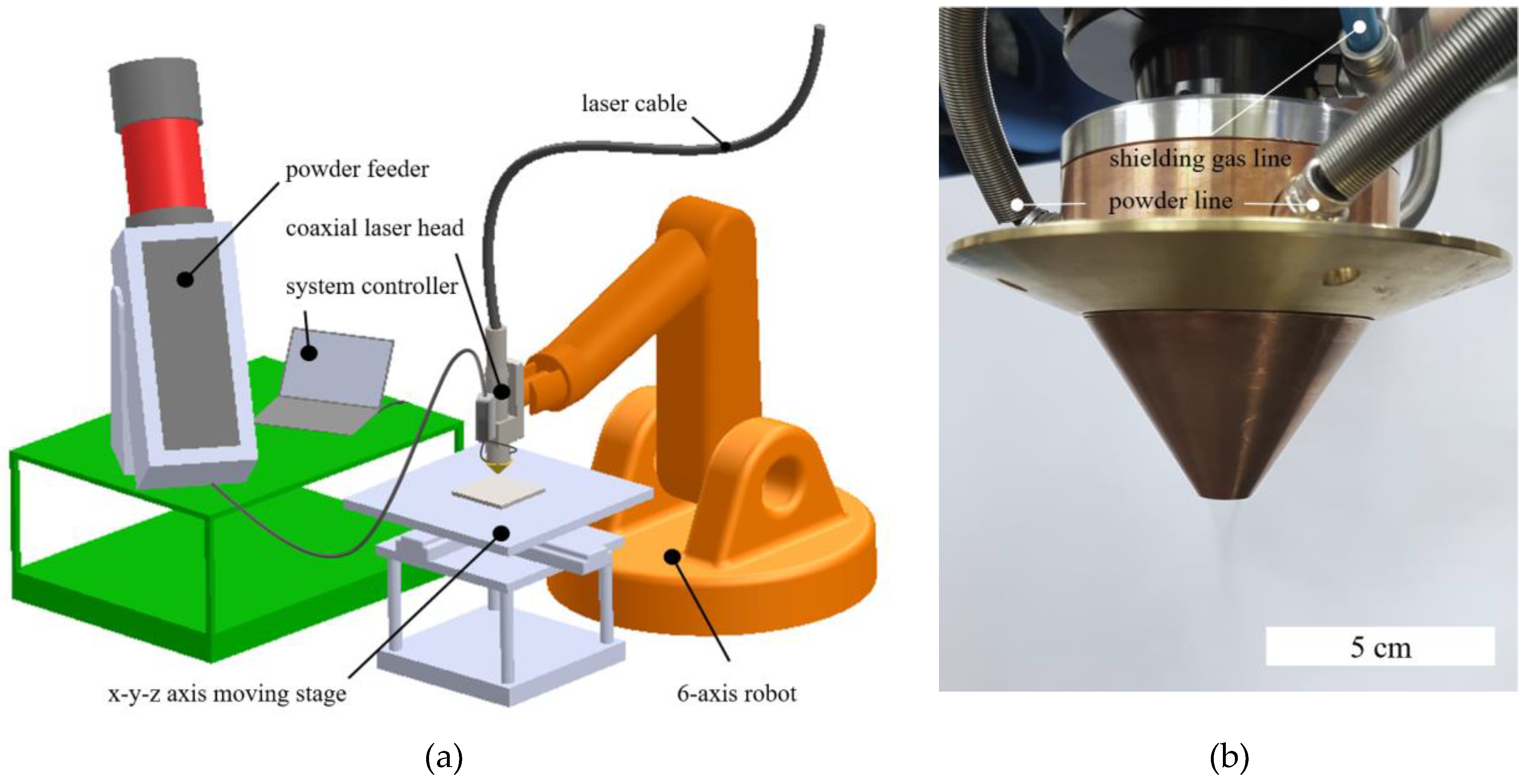
Single layer depositions were carried out using Fe (water atomized powder, CNPC Powder) powder on the mild steel with 12 mm thickness. FGM depositions used the Fe powder and STS316 (gas atomized powder, Praxair) powder on the mild steel substrate. Table 1 shows the chemical composition of each powder. The powder was supplied using a powder feeder (Praxair 1264, Praxair, Concord, NH, USA). During the FGM deposition process, the mixed powders were prepared by ball mill equipment (HBM-800 4R, HANTECH, Gunpo, Korea) of Fe and STS316 at a weight ratio of 3:1, 1:1, and 1:3, respectively. In the ball milling process, a 10 mm diameter stainless steel ball was mixed XHD RY with each powder at a ratio of 10:1 and then mixed at a speed of 200 rpm for 20 h to prepare a mixed powder. The experiments were carried out using a 4 kW Yb:YAG (Yb:Y3Al5O12) disk laser (HLD4002, Trumpf, Erlangen, Germany). In addition, an optical fiber with a diameter of 0.2 mm, an optical system with a focal length of 220 mm, and a laser head coaxially injected with a laser were used. Defocusing the focal point over the base material was used to create a laser beam with a diameter of 3.5 mm. Figure 1a shows the schematic diagram of the experimental setup, and Figure 1b indicates the nozzle part where powders are supplied. The powders are distributed in three ways and are concentrically supplied around the laser beam via the space between the inner cap and the outer cap of nozzle. The laser power, feed rate, injection speed, beam shift, and contact tip to work-piece distance (CTWD) were varied in the evaluation of the single layer deposition. The range of each process parameters and the deposition conditions are shown in Table 2.
A six-axis robot (KR 100-3, Kuka, Augsburg, Germany) and a stage capable of moving in the x-y-z axis were used for deposition process. The two kinds of deposited specimens were fabricated by deposition of five layers with a length of 55 mm, with six passes per layer; the details of deposition conditions are shown in the Table 3. Microstructures and processes were also analyzed using optical microscope (OM, BX51M, Olympus, Tokyo, Japan) and field emission scanning electron microscopy (FE-SEM, Quanta200F, Themo Fisher, Eindhoven, The Netherlands). The phase analysis of sample 2 was performed by X-ray diffractometer (XRD, MiniFlex, Rigaku, Japan) using monochromatic Cu–Kα radiation (λ = 0.154056 nm).
3. Results and Discussion
3.1. Effect of Process Parameters on the Bead Geometry
In order to investigate the effect of process parameters on the bead geometry during the deposition process, a single layer was deposited with Fe powder on mild steel and various properties were evaluated. Most of the STS316 powder (99 wt %) is distributed in the size range from 44 to 150 μm, but the Fe powder is 77 wt % in the range as shown in Table 4. Regarding Fe powder, 21 wt % has a size of less than 44 μm, which is consistent with the presence of a large amount of small particles in Figure 2a,b. Thus, Fe powders have a wide distribution range and a non-uniform shape. On the other hand, STS 316 powder was powder with a spherical shape of between 44 and 150 μm, as shown in Figure 2.
3.1.1. Contact Tip to Work-Piece Distance
Figure 3 shows a cross-section of the beads deposited under various CTWD from 5 mm to 15 mm. When the CTWD was 5 mm, the shape of the beads could not be formed properly, because of the CTWD, the shielding gas and the carrier gas were concentrated in a narrow region and affected the bead shape. In addition, large pores were trapped inside, as shown in Figure 3a. In the case of CTWD of 7 mm, the bead appearance was good, but as in the case of CTWD of 5 mm, large pores were formed inside (Figure 3b). In the case of CTWD of 9 mm, pores were generated inside, but the pore size was smaller than that of 7 mm, as shown in Figure 3c. This is because the CTWD increases and the gas pressure on the bead surface decreases. In the CTWD of 11 mm or more, pores inside the beads were almost removed (Figure 3d–f). As shown in the case of 13 mm and 15 mm, the bead height was increased as the CTWD was increased. In the CTWD, the powder was concentrated in the center, and the beads fell off during processing due to the lack of fusion. As shown in the case of CTWD of 13 mm and 15 mm, the bead height increased as the CTWD increased. In the CTWD of 15 mm or more, the powder was concentrated at the center, and the beads were separated from the base material during processing due to the lack of fusion. In order to obtain a good bead shape, it is important to reduce the influence of the gas pressure and to prevent the lack of fusion.
3.1.2. Beam Shift
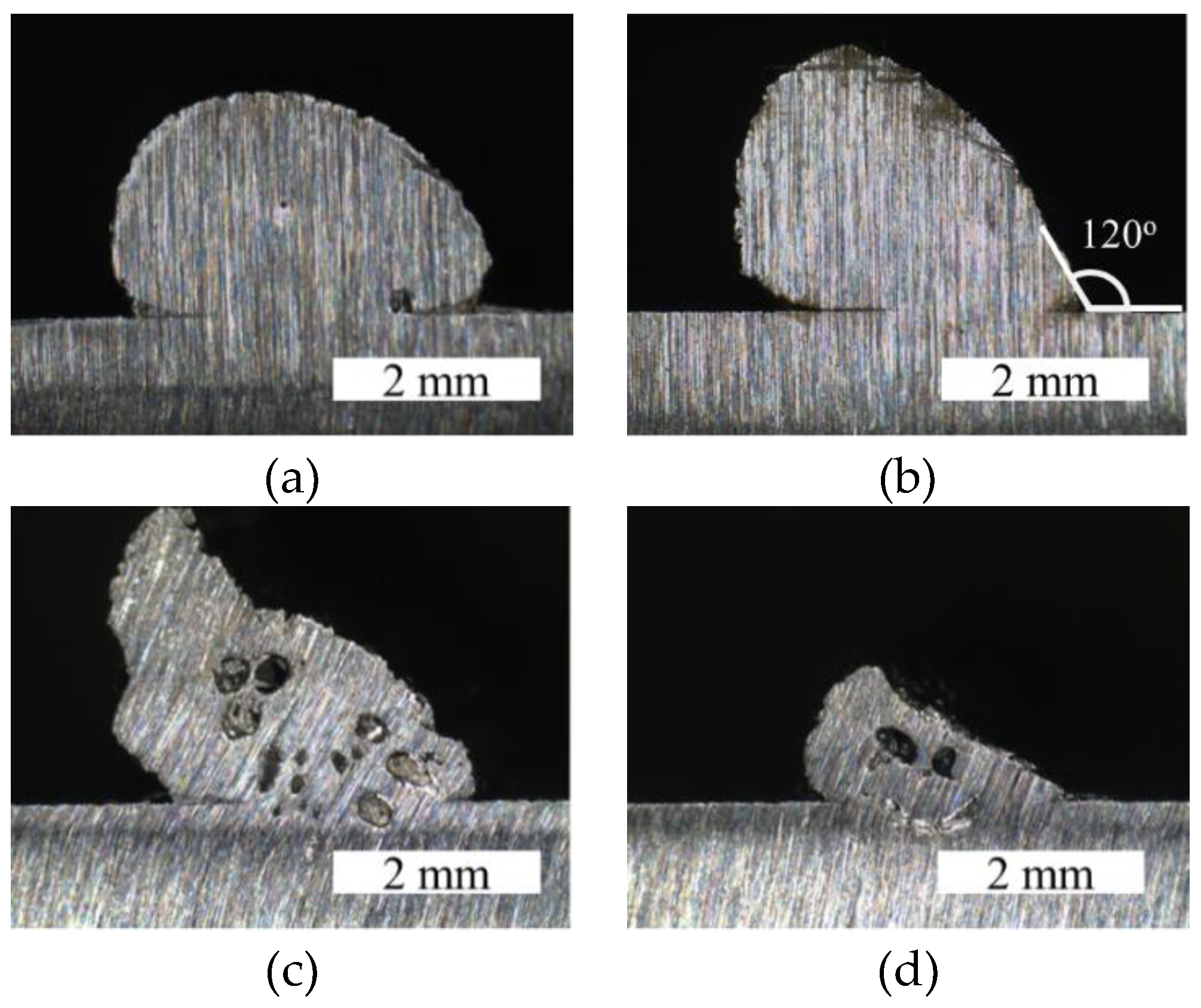
In the laser cladding process, it is generally desired to obtain a good bead by matching the focus of the beam and the powder injection. However, in order to completely cladd the surface, the bead shape of the previous pass is influenced because the multiple passes are overlapped. In addition, when applied to various geometric shapes of base material and welds, techniques are needed to fill various spaces. Therefore, various beam angle or bead shape generation through beam movement was investigated. Figure 4 and Figure 5 show the schematic diagram of beam alignment and cross-section of the bead according to the shift distance of beam, respectively. When the beam shift distance is 0.5 mm (Figure 4b), the beads are asymmetrically formed in the direction of overlapping the beam and powder injection, and then the angle of the back surface increases to 120°. The large angle of the back surface can more effectively control the formation of pores when the next pass is overlapped and cladded. As the amount of powder overlapping between the powder and the beam was larger than when the beam was at the center, the cross-sectional area of the entire bead was increased. However, when the shift distance is 1.0 mm, as shown in Figure 5c, a bead with a certain height is formed on one side, but there are many pores inside. The generation of these pores is due to the asymmetric heat input of the laser beam. When the shift distance of the beam is 2.0 mm, a high enough height of the bead for stacking cannot be obtained, as shown in Figure 5d and pores were inside the bead. As the alignment of the beam and the powder was significantly shifted, the powders did not enter the molten pool and were dispersed into spatters. The asymmetry of the bead increases as the focus of the beam and the powder injection increases, and the angle of the back surface changes and the pore increases inside the bead.
3.1.3. Laser Power
The correlation between the laser power and the shape factor, such as height and width of the bead, is shown in Figure 6. As shown in Figure 6, the bead height and width increased with increasing laser power. When the bead ratio (height/width) was calculated, the laser power also increased the bead ratio. Thus, as shown in the bead ratio, the height of the bead was more influenced by the increase of the laser power.
Figure 7 shows the shape and cross-section of the bead according to the laser power. In the case of laser power of 0.5 kW and 1.0 kW, lack of fusion occurred due to insufficient heat input, and bead was separated from base material and sound bead could not be obtained. When the laser power is 1.5 kW, the bead shape spreads sideways and becomes lower in height. When the laser power increases to 2.0 kW, a sound bead shape can be obtained. As the laser power increased to 2.5 kW, the height and width of the bead became larger, but the pores existed in the upper part of the bead. The reason for this is that the melting pool is formed obliquely and the upper part is formed after the lower part. Therefore, the powders caught in the melting pool late at the upper part are solidified before being sufficiently densified.
3.1.4. Flow Rate
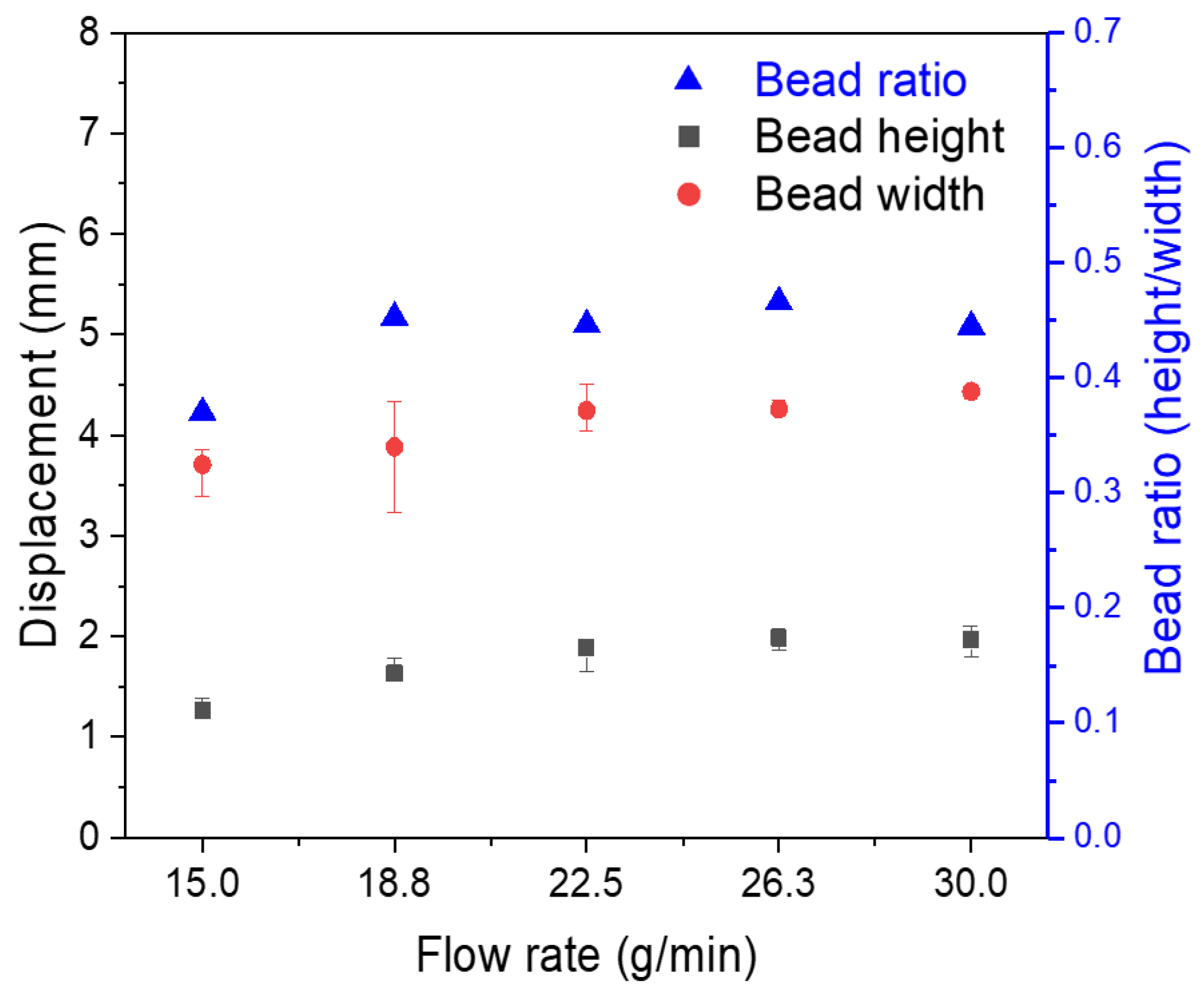
Figure 8 and Figure 9 show the bead height, width, and aspect ratio values and bead appearance and cross-section of bead according to the flow rate, respectively. As shown in Figure 8, the height and width of the beads increase slightly as the flow rate increases. In the area where the sound beads are generated, the aspect ratio did not greatly vary between 0.4–0.5. When the flow rate is 15.0, the amount of powder supplied is insufficient and puckering phenomenon occurs, so that a sound bead cannot be obtained, as shown in Figure 9. At a flow rate of 18.8, a sound bead could be obtained, but some pores were observed. When the flow rate was above 22.5, a sound bead with no pores inside the bead was obtained. As the flow rate is increased, the amount of powder to be injected increases proportionally, but the volume of the bead is maintained and the efficiency of the deposition is deteriorated. Therefore, the flow rate condition is required to be selected in consideration of the deposition efficiency of the powder.
3.1.5. Travel Speed
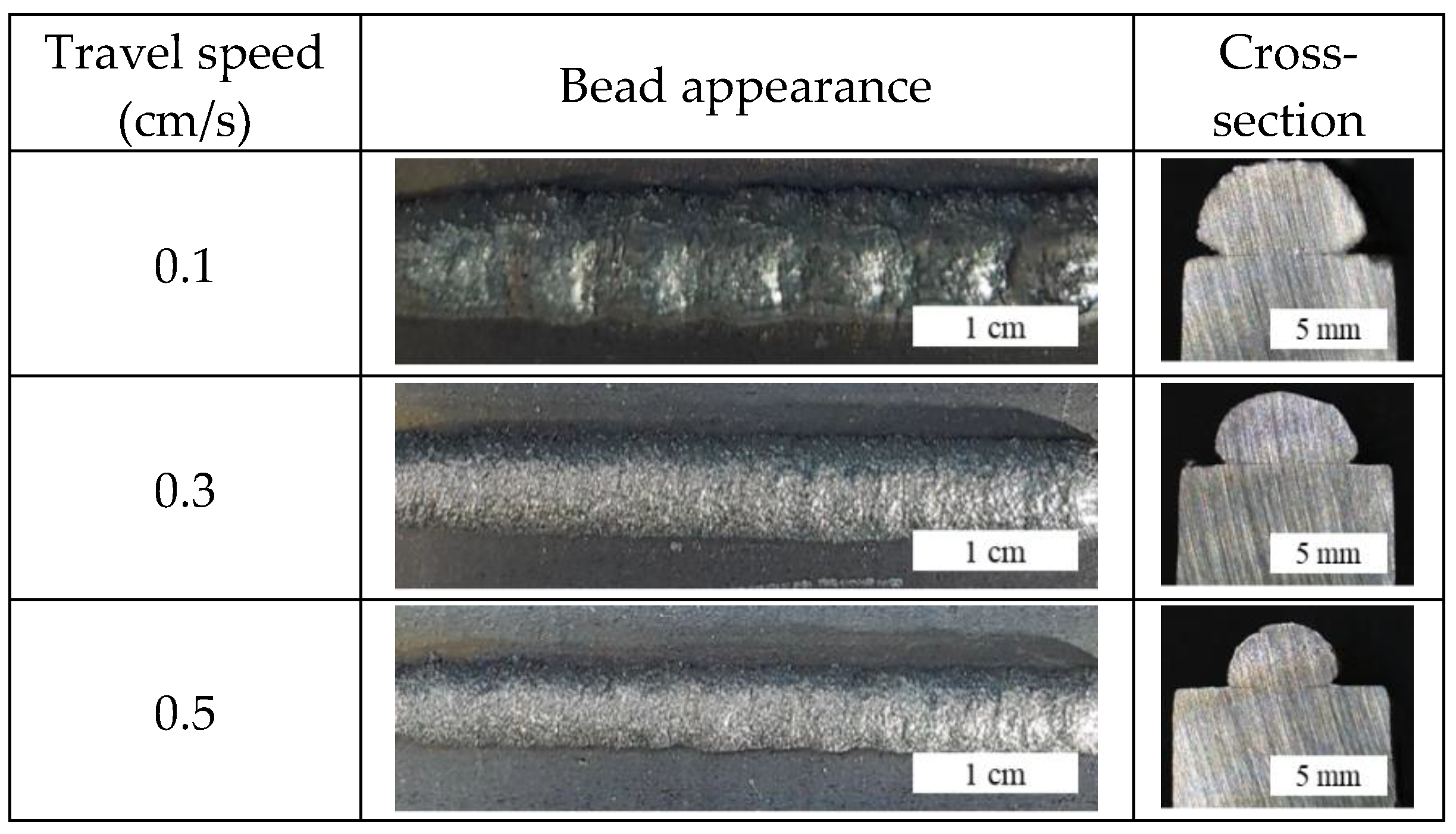
As the travel speed increases, the bead height and width tend to decrease. As shown in Figure 10, when the travel speed is increased from 0.1 cm/s to 0.3 cm/s, the height and width of the bead decrease sharply, and thereafter the decrease is reduced. Also, the deviation in the height and width of the beads increased at speeds of lower than 0.2 cm/s or higher than 0.9 cm/s. The formation of internal pores due to the humping beads at high speed and at low speeds also affects the bead appearance.
Figure 11 shows the bead appearance and cross-section of the bead at various travel speeds. The molten pool generated by the laser cladding has a large temperature gradient and surface tension, which forms a high fluid flow [25]. When travel speed is low, such as 0.1 cm/s, the temperature gradient and surface tension are reduced by the high heat input as fluid flow decreases, forming a hump surface. As the travel speed increased to 0.3 and 0.5 cm/s, a sound bead with no porosity was obtained. Also, by changing the travel speed, a defect-free bead with a high bead ratio of 0.65 was obtained. However, when the travel speed was 0.9 cm/s, the bead appearance seemed to be sound, but pores were observed inside. In the case of travel speed of 1.1 cm/s, pores were observed both inside and outside of the bead. When the travel speed is increased, the solidification time is not enough for densification of the powder, so that the pores are increased.
The effect of process variables on the bead shape was investigated using Fe powder of an uneven shape and the optimal process variable interval to obtain a defect-free bead, shown in Table 5. The sound bead showed a bead ratio of 0.4–0.65 with change of variables. According to a study [26] comparing the powder feeding method with the wire feeding method, the powder feeding method is capable of cladding under significantly more variable condition. Thus, in spite of the nonuniform powder with a wide distribution shown as Table 4, the defect-free bead could be formed.
3.2. Additive Manufacturing
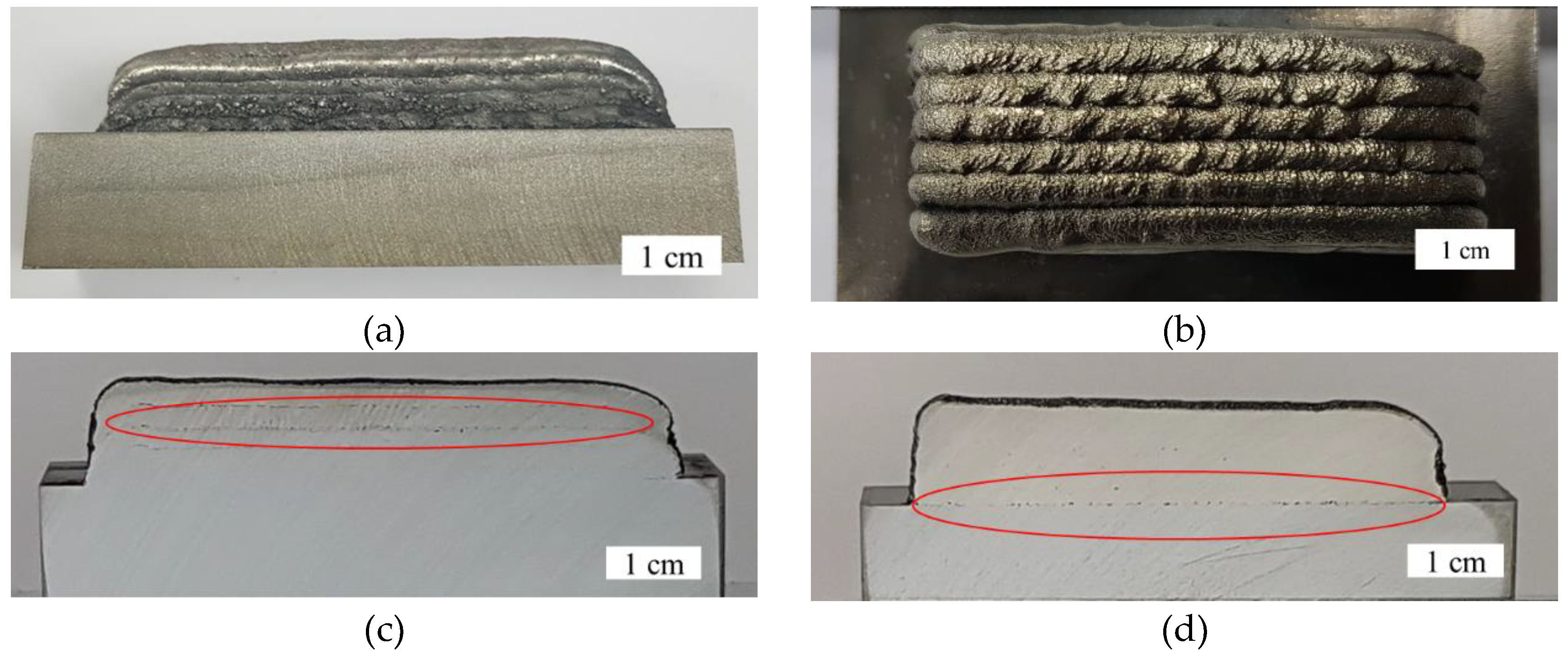
Figure 12a–c show a cladding sample of the STS316/Fe functionally graded material of 100% Fe, 25% STS316 + 75% Fe, 50% STS316 + 50% Fe, 75% STS316 + 75% Fe, and 100% STS316 powder on the mild steel plate. Each powder having a composition of 100% Fe, 25% STS 316 + 75% Fe, 50% STS 316 + 50% Fe, 75% STS 316 + 75% Fe, and 100% STS 316 was cladded in total by five layers and six layers were cladded in the width direction. Figure 12c,d shows the cross sections of the two types of deposited samples mentioned in Table 3. When the STS316 powder was directly deposited on the mild steel, there was a pore between the first layer and the substrate, as shown in Figure 12d with a red circle. The defects at the interface continued to exist even if the deposition by any change of aforementioned parameters is used. However, no pores at existed the interfaces above the second layer, which was deposited between the same STS316. The spherical STS316 powder was well deposited under given conditions. As shown in Figure 12c, when the functionally graded material was prepared using Fe powder with an irregular shape and size, pores did not appear in the lower layer. However, porosity increased as the content of STS316 powder increased, which is discussed later. Therefore, Fe powder is used, and the pores of the first layer with the mild steel can be removed effectively.
Figure 13 shows the microstructures of the first layer in the sample 1 and 2 by OM, respectively. Sample 1 with mild steel / STS316 interface, as shown in Figure 13a, had a distinct interface between the two materials. As a result of such an interfacial structure, cracks and peeling occurred in the interfacial region when deposition was performed in multiple passes. On the other hand, when the FGM was manufactured using Fe powder, it was bonded systematically at the interface, as shown in Figure 13b. In the case of FGM, thermal stress and thermal deformation can be reduced using a gradually changing thermal expansion coefficient between layers [27]. The thermal expansion coefficient of STS316 is about 17.2 × 10⁻⁶/°C [28,29]. The thermal expansion coefficient of pure Fe increases from 12.3 × 10⁻⁶/°C to 16.2 × 10⁻⁶/°C depending on the temperature [30]. In addition, the thermal expansion coefficient of mild steel is about 12.0 × 10⁻⁶/°C [28,29]. Fe can reduce the difference in thermal expansion coefficient compared to direct bonding of mild steel to STS316. When using Fe, the difference in thermal expansion coefficient can be reduced compared with direct bonding of mild steel and STS316. Therefore, the interfacial bonding property between Fe and mild steel is improved compared with the interfacial bonding property between STS316 and mild steel.
Figure 14 shows the energy dispersive spectrometer (EDS) line scanning results of the FGM specimen. The composition of each element changes from the base material to the upper layer. Cr and C are concentrated and distributed between the interfaces, while Fe is relatively deficient in the region. Figure 15 shows the shaeffler diagrams, which were drawn by calculating Cr and Ni equivalent value using composition, are useful to analyze the change of phase in austenitic steel welding. Seventy-five Fe and 25Fe place on a martensite single phase region, 0Fe is a austenite single phase, and 50Fe is predicted a mixed phase of these two phase. In XRD analysis, as shown in Figure 16, 100Fe and 75Fe detected only ferrite/martensite peak (α) and 0Fe has a austenite peak (γ) with relatively high intensity. Twenty-five Fe and 50 Fe has mixed peak with α and γ phase, thus the result of 50Fe is opposite to the schaeffler diagram. Thus, the mixed phase region between austenite and martensite could be extended in the process condition. In the FGM, remelting and re-solidification between layers lead to change composition and phase. Especially, in these systems, the tetragonal structured sigma phase, which is usually formed at interface between α and γ phase, is brittle with low toughness, resulting in fracture [15]. However, there was no XRD peak associated sigma phase at any layer of sample 2, because the fast cooling rate of the laser travel speed could control it.
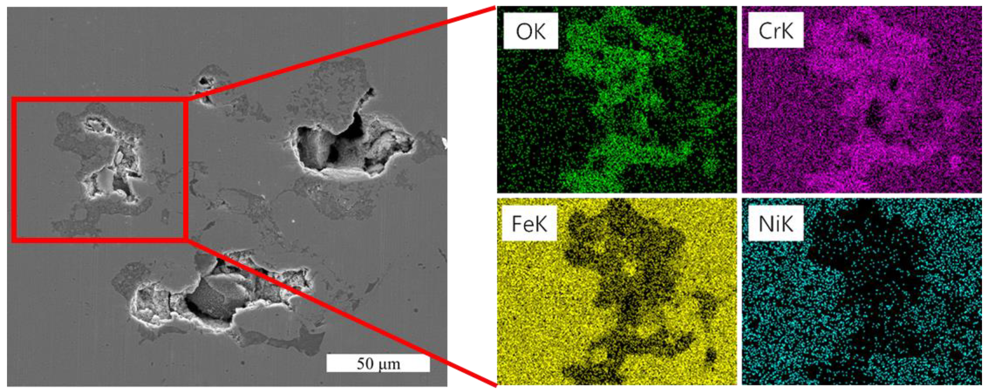
In the case of FGM, which was deposited using a mixture of STS 316 and Fe powder, pores were present between the layers, as shown in Figure 12c with a red circle. In order to investigate the cause of pore formation in the interlayer, EDS mapping was performed on the pore region. As shown in Figure 17, the relatively high content of Cr and oxygen around the pores of the EDS mapping indicates that chrome oxide is formed. Carbon segregation exists at the interface of the second layer, and segregation of Cr is observed at the interface between each layer from the second layer. Segregation of these elements is a cause of pores and causes deterioration of physical properties at the interface. Therefore, it is necessary to reduce the pore between the interfaces by considering the contents of Cr and C, in addition to changing the composition of the FGM using Fe powder.
4. Conclusions
FGM was fabricated by laser direct metal deposition using STS316 and Fe powders. The effect of each type parameters on the physical properties was observed. The details are as follows.
- The process conditions for producing sound beads without humping beads, pores, and lack of fusion were derived using Fe powder with uneven size and shape.
- The shape of the bead and the size of the pore were affected by the change of CTWD. The beam shift parameter had the effect of changing the angle of the bead, and the laser power was effective in changing the aspect ratio of the bead.
- Low flow rates caused puckering, while excessive flow rates reduced material efficiency. In addition, humping beads were observed at slow travel speed and many pores due to rapid solidification at high travel speed.
- The FGM samples showed gradual changes in composition and phase along the layers. In XRD analysis, any intermetallic compounds such as sigma phase was not detected.
- When the STS316 was directly deposited on the mild steel, there were many pores and cracks at the interface. However, when the FGM was produced by using Fe and STS316 powder, defects occurring at the interface of the first layer could be removed.
- However, as the Fe powder was mixed with STS316 powder, pores were observed between the interfaces, which resulted in the presence of chrome oxide at the interface.
Author Contributions
Investigation, S.N. and H.C.; Methodology, S.N. and Y.-M.K.; Supervision, C.K. and Y.-M.K.; Writing—original draft, S.N.; Writing—review & editing, Y.-M.K.
Funding
This research was funded by the Korea Institute of Industrial Technology.
Acknowledgments
The authors would like to acknowledge the support provided by the Korea Institute of Industrial Technology.
Conflicts of Interest
The authors declare no conflict of interest.
References
- Hwang, M.J.; Cho, J. Laser additive manufacturing technology review. J. Weld. Joining 2014, 32, 15–19. [Google Scholar] [CrossRef]
- Sun, Z.; Ion, J. Laser welding of dissimilar metal combinations. J. Mater. Sci. 1995, 30, 4205–4214. [Google Scholar] [CrossRef]
- Urbikain, G.; Perez, J.M.; López de Lacalle, L.N.; Andueza, A. Combination of friction drilling and form tapping processes on dissimilar materials for making nutless joints. Proc. Inst. Mech. Eng. Part B 2016, 232, 1007–1020. [Google Scholar] [CrossRef]
- Goodarzi, D.M.; Pekkarinen, J.; Salminen, A. Analysis of laser cladding process parameter influence on the clad bead geometry. Weld. World 2017, 61, 883–891. [Google Scholar] [CrossRef]
- Saqib, S.; Urbanic, R.J.; Aggarwal, K. Analysis of laser cladding bead morphology for developing additive manufacturing travel paths. Procedia CIRP 2014, 17, 824–829. [Google Scholar] [CrossRef]
- Oliveira, U.D.; Ocelik, V.; Hosson, J.T.M.D. Analysis of coaxial laser cladding processing conditions. Surf. Coat. Technol. 2005, 197, 127–136. [Google Scholar] [CrossRef]
- Calleja, A.; Tabernero, I.; Fernández, A.; Celaya, A.; Lamikiz, A.; López de Lacalle, L.N. Improvement of strategies and parameters for multi-axis laser cladding operations. Opt. Lasers Eng. 2014, 56, 113–120. [Google Scholar] [CrossRef]
- Calleja, A.; Tabernero, I.; Ealo, J.A.; Campa, F.J.; Lamikiz, A.; de Lacalle, L.N.L. Feed rate calculation algorithm for the homogeneous material deposition of blisk blades by 5-axis laser cladding. Int. J. Adv. Manuf. Technol. 2014, 74, 1219–1228. [Google Scholar] [CrossRef]
- Brentrup, G.; Dupont, J. Fabrication and characterization of graded transition joints for welding dissimilar alloys. Weld. J. 2013, 92, 72–79. [Google Scholar]
- Shah, K.; Haq, I.U.; Khan, A.; Shah, S.A.; Khan, M.; Pinkerton, A.J. Parametric study of development of Inconel-steel functionally graded materials by laser direct metal deposition. Mater. Des. 2014, 54, 531–538. [Google Scholar] [CrossRef]
- Wu, D.; Liang, X.; Li, Q.; Jiang, L. Laser rapid manufacturing of stainless steel 316L/Inconel718 functionally graded materials: Microstructure evolution and mechanical properties. Int. J. Opt. 2010, 2010, 1–5. [Google Scholar] [CrossRef]
- Reichardt, A.; Dillon, R.P.; Borgonia, J.P.; Shapiro, A.A.; Mcenerney, B.W.; Momose, T.; Hosemann, P. Development and characterization of Ti-6Al-4V to 304L stainless steel gradient components fabricated with laser deposition additive manufacturing. Mater. Des. 2016, 104, 404–413. [Google Scholar] [CrossRef]
- Li, W.; Karnati, S.; Kriewall, C.; Liou, F.; Newkirk, J.; Brown Taminger, K.M.; Seufzer, W.J. Fabrication and characterization of a functionally graded material from Ti-6Al-4V to SS316 by laser metal deposition. Addit. Manuf. 2017, 14, 95–104. [Google Scholar] [CrossRef]
- Li, W.; Liou, F.; Newkirk, J.; Brown Taminger, K.M.; Seufzer, W.J. Ti6Al4V/SS316 multi-metallic structure fabricated by laser 3d printing and thermodynamic modeling prediction. Int. J. Adv. Manuf. Technol. 2017, 92, 4511–4523. [Google Scholar] [CrossRef]
- Li, W.; Liou, F.; Newkirk, J.; Taminger, K.M.B.; Seufzer, W.J. Investigation on Ti6Al4V-V-Cr-Fe-SS316 multi-layers metallic structure fabricated by laser 3D printing. Sci Rep. 2017, 7, 7977. [Google Scholar] [CrossRef] [PubMed]
- Hofmann, D.C.; Roberts, S.; Otis, R.; Kolodziejska, J.; Dillon, R.P.; Suh, J.O.; Shapiro, A.A.; Liu, Z.K.; Borgonia, J.P. Developing gradient metal alloys through radial deposition additive manufacturing. Sci. Rep. 2014, 4, 5357. [Google Scholar] [CrossRef] [PubMed]
- Zhang, C.; Zhang, H.; Wu, C.; Zhang, S.; Sun, Z.; Dong, S. Multi-layer functional graded stainless steel fabricated by laser melting deposition. Vacuum 2017, 141, 181–187. [Google Scholar] [CrossRef]
- Li, W.; Yan, L.; Chen, X.; Zhang, J.; Zhang, X.; Liou, F. Directed energy depositing a new Fe-Cr-Ni alloy with gradually changing composition with elemental powder mixes and particle size’ effect in fabrication process. J. Mater. Process. Technol. 2018, 255, 96–104. [Google Scholar] [CrossRef]
- Fatima, S.; Khan, M.; Jaffery, S.H.I.; Ali, L.; Mujahid, M.; Butt, S.I. Optimization of process parameters for plasma arc welding of austenitic stainless steel (304 L) with low carbon steel (A.-36). Proc. Inst. Mech. Eng. Part L 2015, 230, 640–653. [Google Scholar] [CrossRef]
- Klueh, R.; King, J. Austenitic stainless steel-ferritic steel weld joint failures. Weld. J. 1982, 61, 302–311. [Google Scholar]
- Dupont, J.N. Microstructural evolution and high temperature failure of ferritic to austenitic dissimilar welds. Int. Mater. Rev. 2013, 57, 208–234. [Google Scholar] [CrossRef]
- Chuaiphan, W.; Chandra-Ambhorn, S.; Sornil, B.; Bleck, W. Microstructure, mechanical and corrosion behaviour of dissimilar weldments between AISI 304 stainless steels and AISI 1020 carbon steels produced by gas tungsten arc welding using different consumables. Key Eng. Mater. 2009, 410–411, 533–541. [Google Scholar] [CrossRef]
- Li, W.; Zhang, J.; Zhang, X.; Liou, F. Effect of optimizing particle size on directed energy deposition of functionally graded material with blown pre-mixed multi-powder. Manuf. Lett. 2017, 13, 39–43. [Google Scholar] [CrossRef]
- Hwang, J.H.; Shin, S.S.; Jung, G.I.; Kim, S.W.; Kim, H.D. A study on the characteristics of laser deposition surface and cross-section for metal powder. J. Weld. Joining 2016, 34, 17–22. [Google Scholar] [CrossRef]
- Qi, H.; Mazumder, J.; Ki, H. Numerical simulation of heat transfer and fluid flow in coaxial laser cladding process for direct metal deposition. J. Appl. Phys. 2006, 100. [Google Scholar] [CrossRef] [Green Version]
- Kam, D.H.; Kim, Y.M.; Kim, C. Recent studies of laser metal 3D deposition with wire feeding. J. Weld. Joining 2016, 34, 35–40. [Google Scholar] [CrossRef]
- Noda, N. Thermal stresses in functionally graded materials. J. Therm. Stress. 1999, 22, 477–512. [Google Scholar] [CrossRef]
- Charde, N.; Yusof, F.; Rajkumar, R. Material characterizations of mild steels, stainless steels, and both steel mixed joints under resistance spot welding (2-mm sheets). Int. J. Adv. Manuf. Tech. 2014, 75, 373–384. [Google Scholar] [CrossRef]
- Song, Y.A.; Park, S. Experimental investigations into rapid prototyping of composites by novel hybrid deposition process. J. Mater. Process. Technol. 2006, 171, 35–40. [Google Scholar] [CrossRef]
- Cleaves, H.E.; Hiegel, J.M. Properties of high-purity iron. J. Res. Natl. Bur. Stand. 1942, 28, 643–667. [Google Scholar] [CrossRef]
Figure 1.
(a) Schematic diagram of experimental setup and (b) image of coaxial nozzle.

Figure 2.
FE-SEM images for powder morphology. (a) Fe powder at low magnification, (b) Fe powder at high magnification, (c) STS316 at low magnification, and (d) STS316 at high magnification.
Figure 2.
FE-SEM images for powder morphology. (a) Fe powder at low magnification, (b) Fe powder at high magnification, (c) STS316 at low magnification, and (d) STS316 at high magnification.
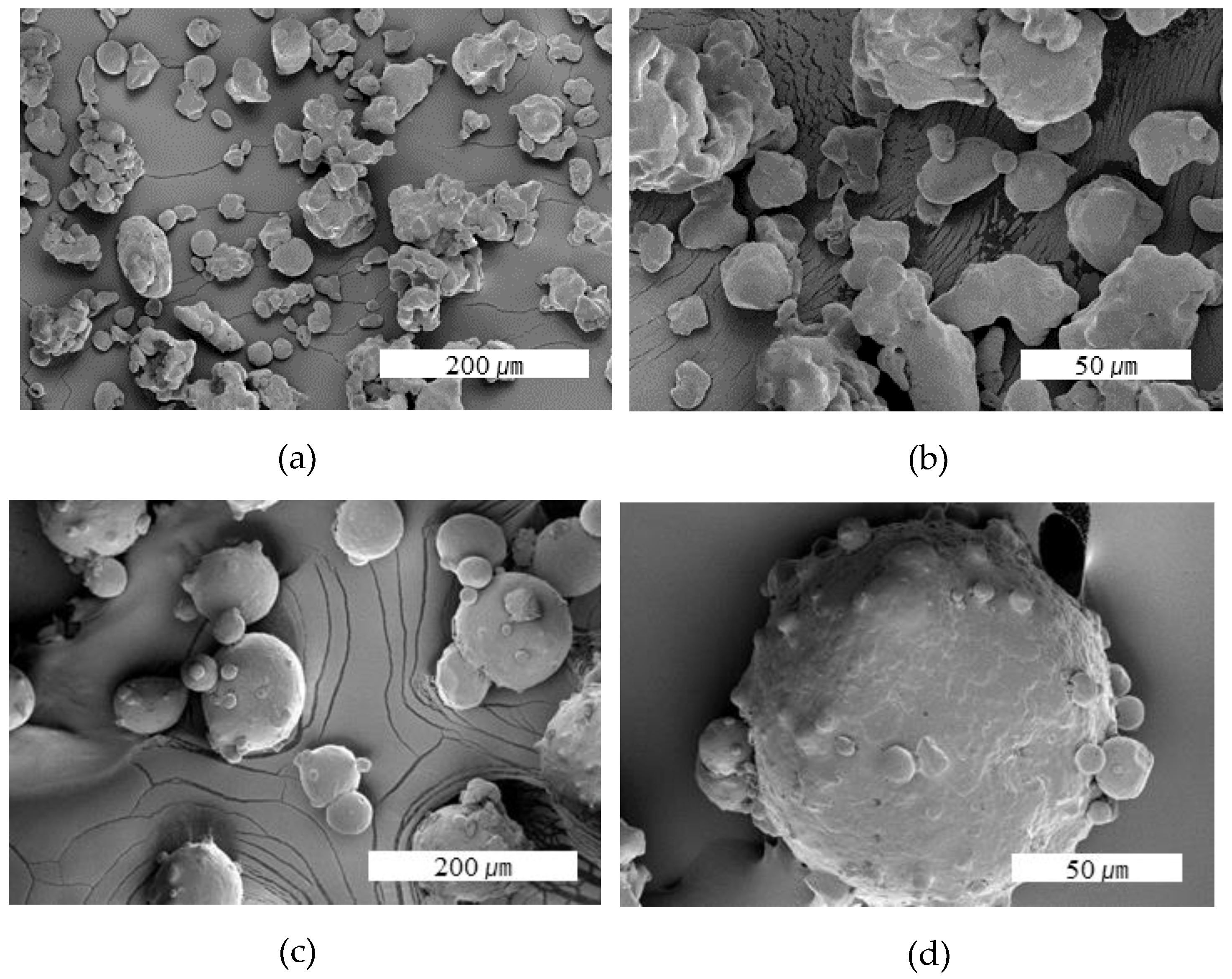
Figure 3.
Cross section of bead with various contact tip to work-piece distance (a) 5 mm, (b) 7 mm, (c) 9 mm, (d) 11 mm, (e) 13 mm, and (f) 15 mm.
Figure 3.
Cross section of bead with various contact tip to work-piece distance (a) 5 mm, (b) 7 mm, (c) 9 mm, (d) 11 mm, (e) 13 mm, and (f) 15 mm.
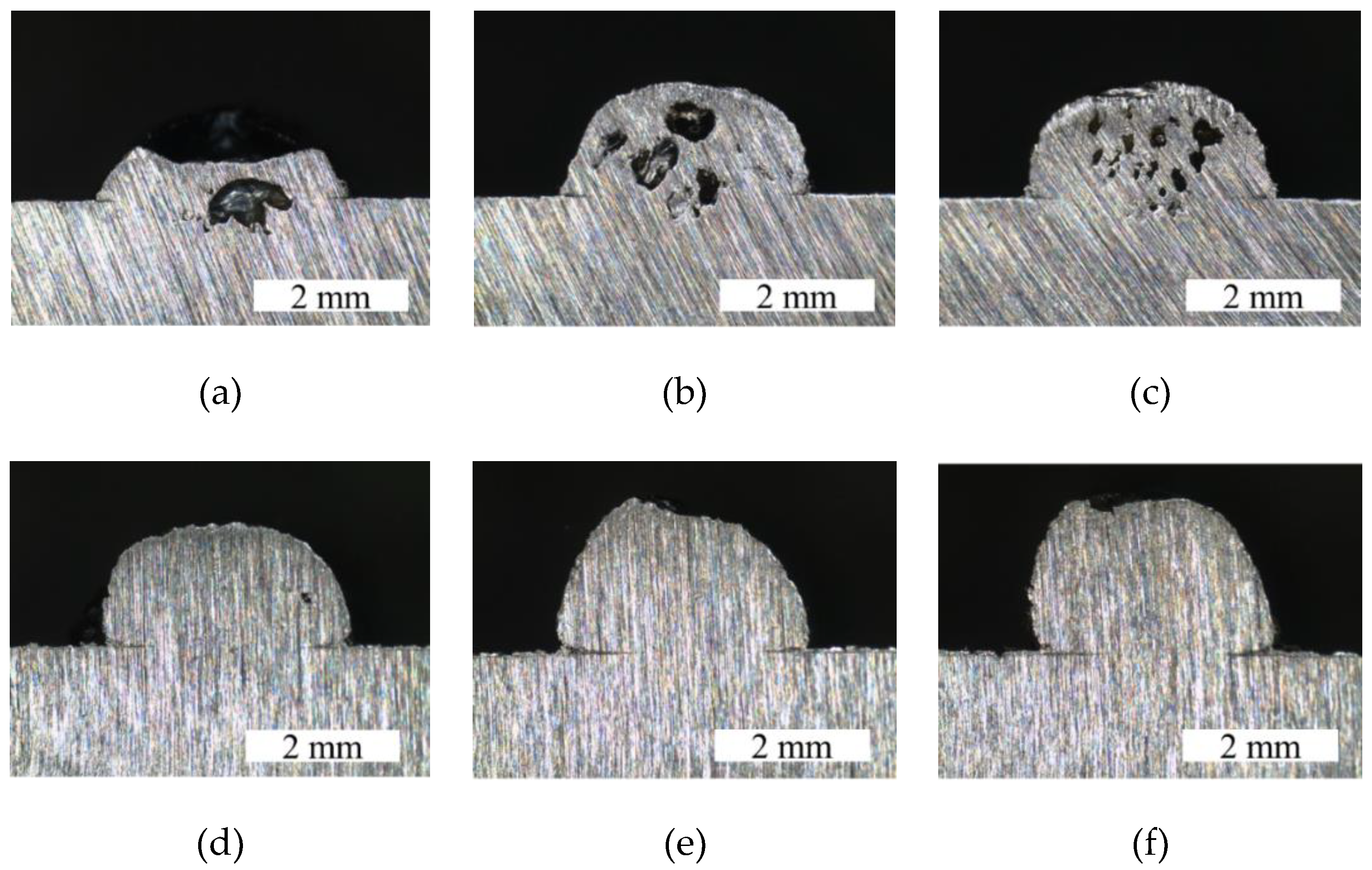
Figure 4.
Schematic diagram of beam alignment: (a) center beam, (b) 0.5 mm shifted beam.

Figure 5.
Cross-section of bead with various shift distance of beam (a) 0 mm, (b) 0.5 mm, (c) 1 mm, and (d) 2 mm.
Figure 5.
Cross-section of bead with various shift distance of beam (a) 0 mm, (b) 0.5 mm, (c) 1 mm, and (d) 2 mm.

Figure 6.
Bead height, width, and aspect ratio with various laser power.
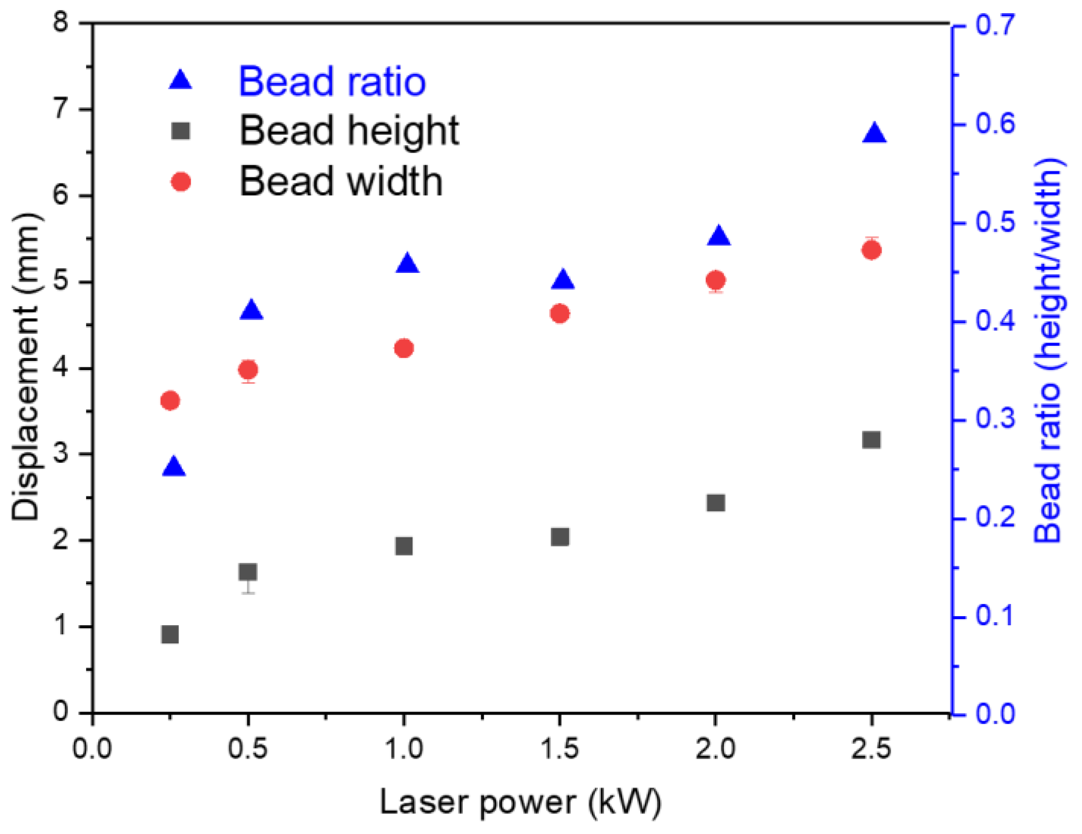
Figure 7.
Bead appearance and cross-section of bead with various laser power from 0.5 kW to 2.5 kW.
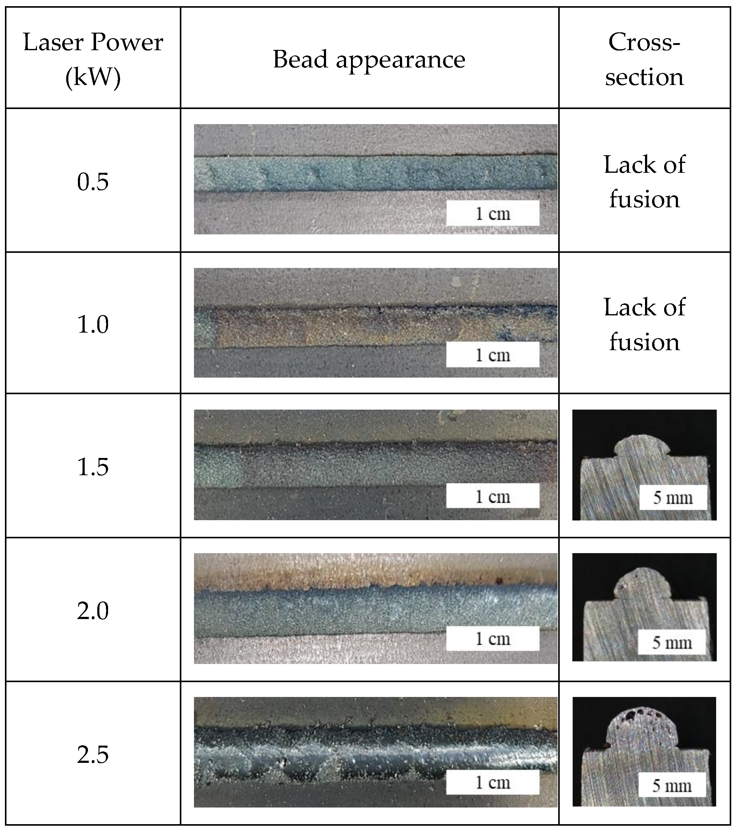
Figure 8.
Bead height, width, and aspect ratio with various flow rates of Fe powder.

Figure 9.
Bead appearance and cross-section of bead with various flow rate from 15.0 to 30.0 g/min.
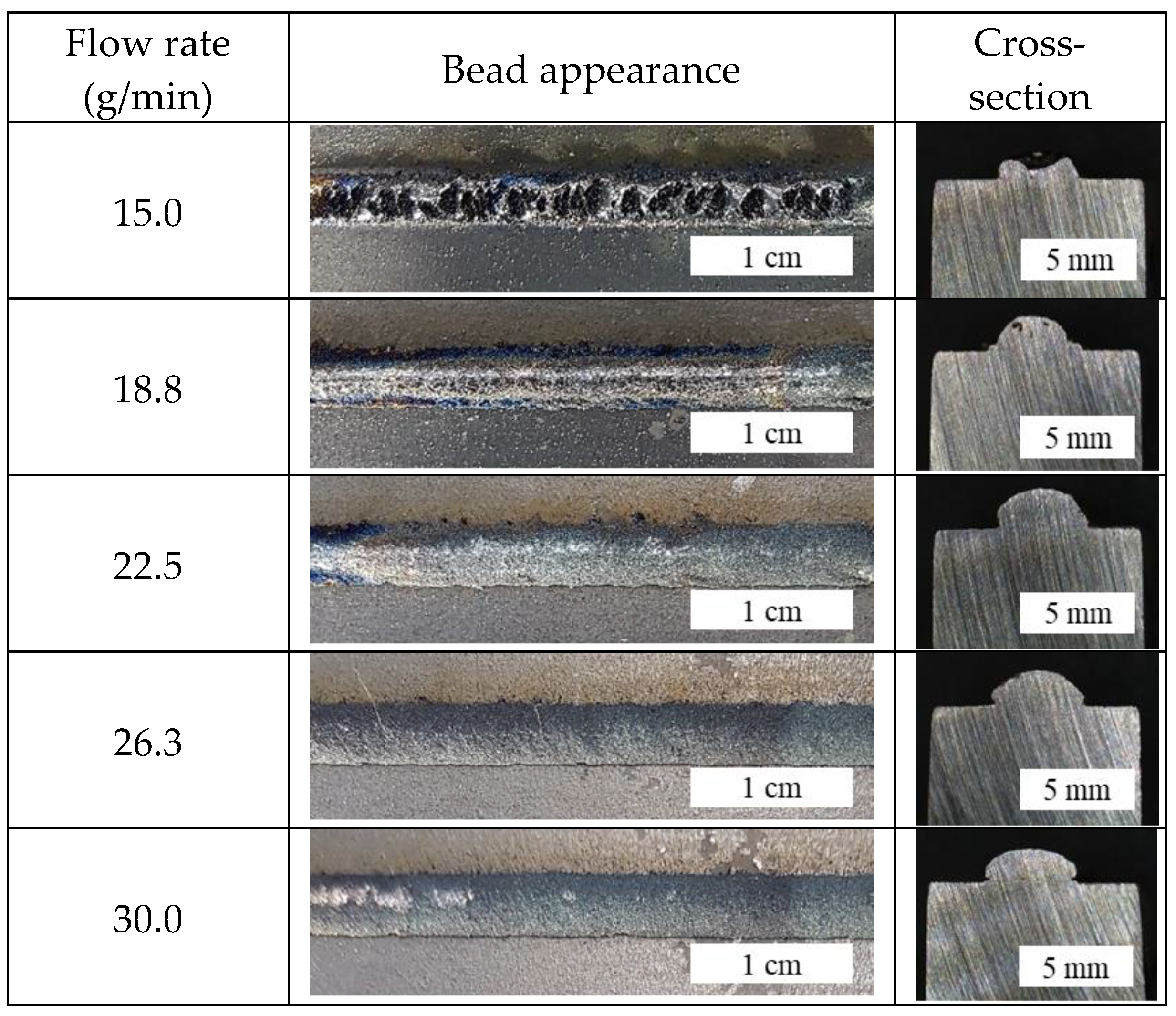
Figure 10.
Bead height, width, and aspect ratio with various travel speed.
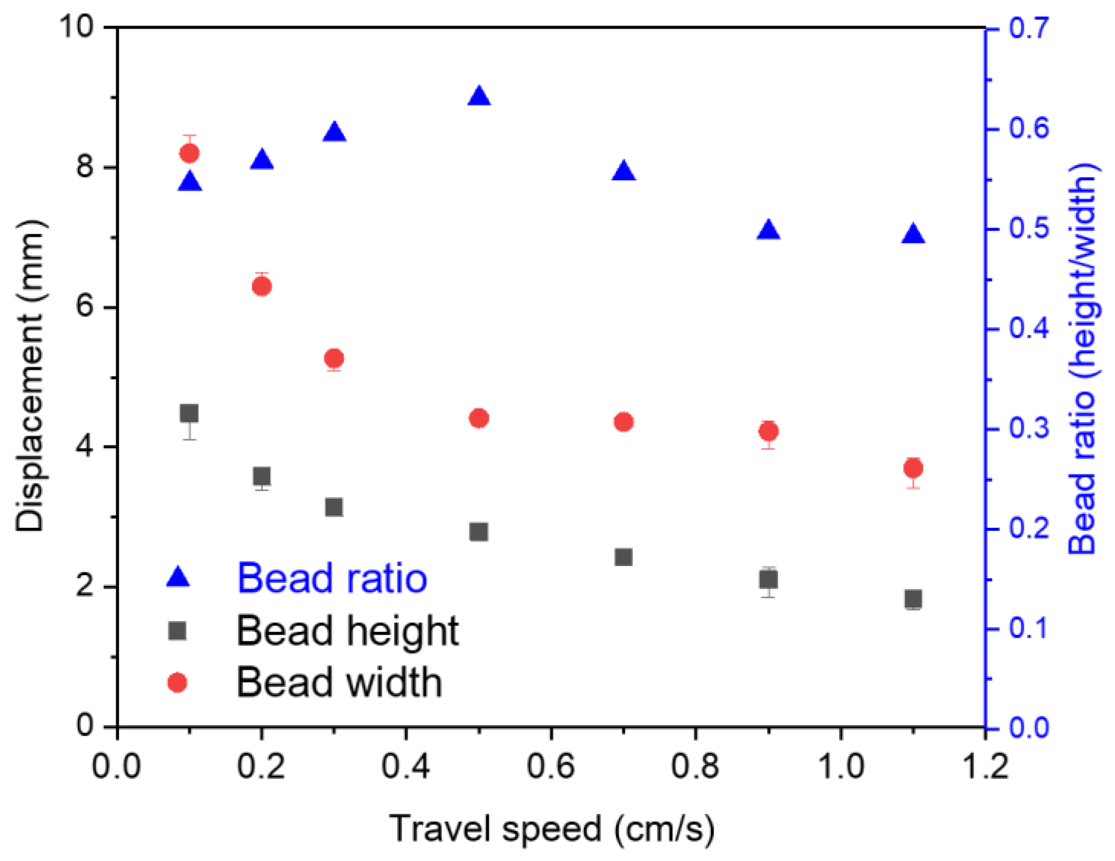
Figure 11.
Bead appearance and cross-section of bead with various travel speed.

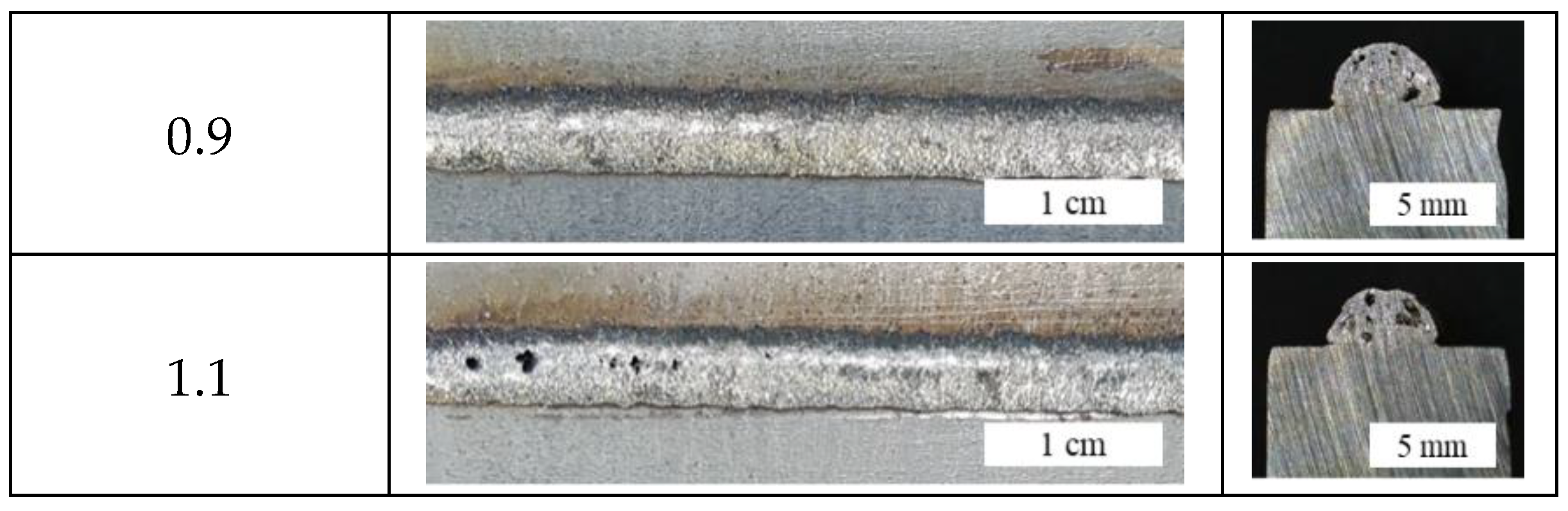
Figure 12.
(a) Side view, (b) top view, (c) cross-section view of the sample after laser cladding of the STS316/Fe functionally graded material, and (d) cross-section view of the sample after dissimilar cladding between STS316 and Fe (red circle indicates pore generated region).
Figure 12.
(a) Side view, (b) top view, (c) cross-section view of the sample after laser cladding of the STS316/Fe functionally graded material, and (d) cross-section view of the sample after dissimilar cladding between STS316 and Fe (red circle indicates pore generated region).

Figure 13.
Microstructure of interface between (a) sample 1 and (b) sample 2.
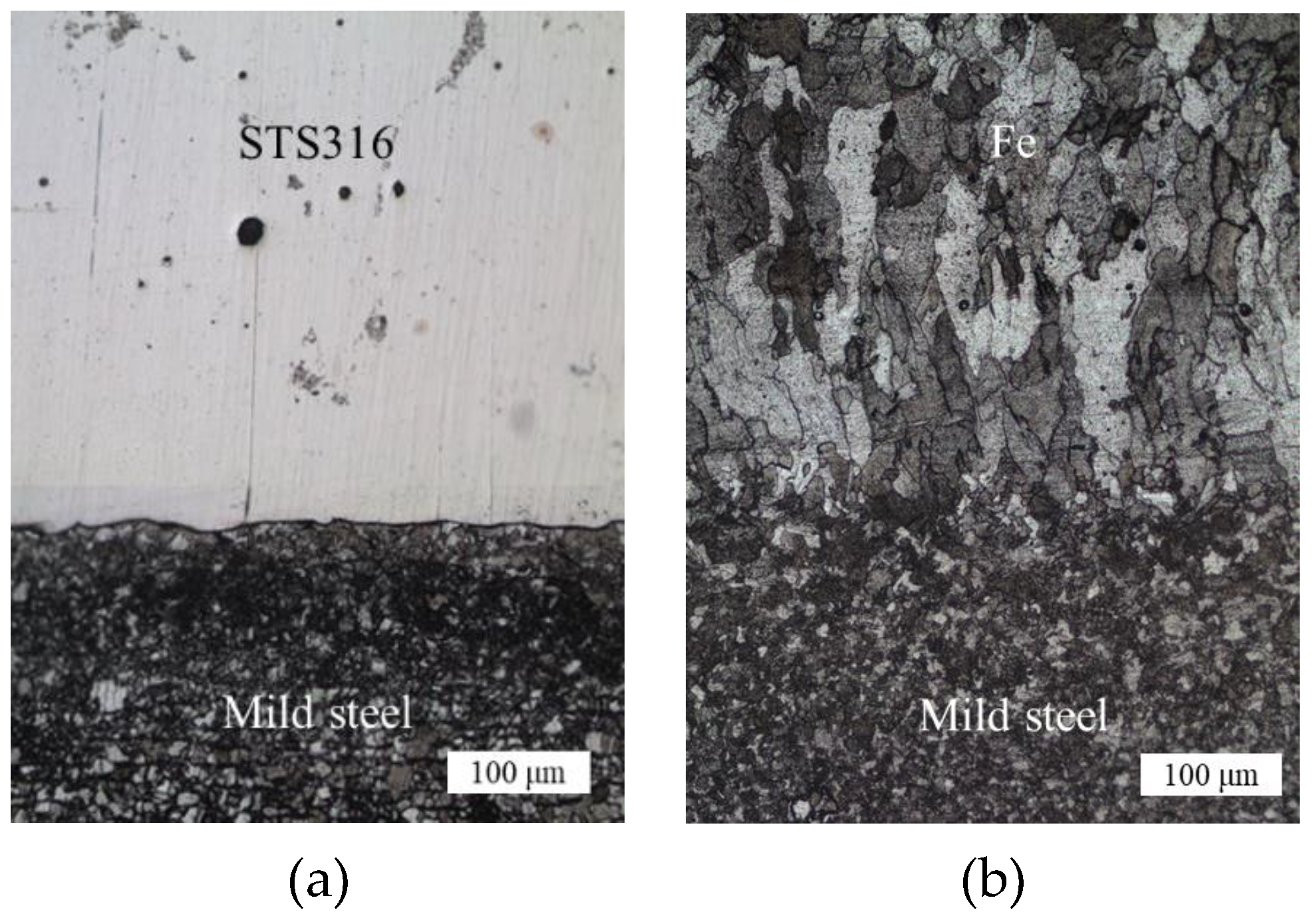
Figure 14.
The result of energy dispersive spectrometer (EDS) line scanning for the mild steel/Fe(B) + STS316.
Figure 14.
The result of energy dispersive spectrometer (EDS) line scanning for the mild steel/Fe(B) + STS316.
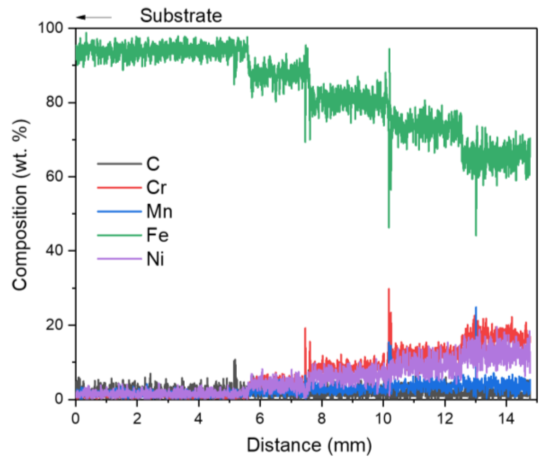
Figure 15.
Schaeffler diagram representing the predicted phase of each composition.

Figure 16.
X-ray diffractometer (XRD) patterns at different layer along the composition gradient obtained for sample 2.
Figure 16.
X-ray diffractometer (XRD) patterns at different layer along the composition gradient obtained for sample 2.

Figure 17.
The result of EDS mapping for the interface pores of sample 2.

Table 1.
Chemical composition of powders used in this study.
| Powder | Fe | C | O | Si | Mn | P | S | Ni | Cr | Mo |
|---|---|---|---|---|---|---|---|---|---|---|
| STS316 | Bal. | 0.02 | 0.03 | 0.01 | 1.06 | 0.005 | 0.003 | 12.00 | 17.00 | 2.04 |
| Fe | Bal. | 0.01 | 0.15 | 0.08 | 0.13 | 0.008 | 0.006 | 0.005 | 0.005 | 0.003 |
Table 2.
Various parameters for deposition used in this study.
| Process Parameter | Single Pass | Build Production |
|---|---|---|
| Laser Power (kW) | 0.5–2.5 [2] | 2 |
| Travel speed (m/s) | 0.001–0.01 [0.005] | 0.0083 |
| Flow rate (g/min) | 15–30 [20] | 30 |
| Beam Shift (mm) | 0–2 [0] | 0 |
| Contact tip to work-piece distance (mm) | 5–15 [10] | 10–11 |
| Shielding gas (L/min) | 15 (Ar) | 15 (Ar) |
| Carrier gas (L/min) | 10 (Ar) | 10 (Ar) |
* The value in [] is used as the default value when evaluating the variable.
Table 3.
Deposition sequence used in this study.
| Sample | Sample 1 (Dissimilar Welding) | Sample 2 (Functionally Graded Materials) | |
|---|---|---|---|
| Composition (wt %) | Composition (wt %) | Layer Name | |
| 5th layer | STS316 | 100% STS316 | 0Fe |
| 4th layer | STS316 | 75% STS316 + 25% Fe | 25Fe |
| 3rd layer | STS316 | 50% STS316 + 50% Fe | 50Fe |
| 2nd layer | STS316 | 75% STS316 + 25% Fe | 75Fe |
| 1st layer | STS316 | 100% Fe | 100Fe |
| Substrate | Mild steel | Mild steel | |
Table 4.
Powder distribution measeured by sieve analysis.
| Sieve Number | Particle Size (μm) | Distribution (wt %) * | |
|---|---|---|---|
| Fe | STS316 | ||
| 100 | >150 | 2 | - |
| 140 | 105–150 | 18 | 99 |
| 200 | 74–105 | 29 | |
| 325 | 44–74 | 30 | |
| −325 | <44 | 21 | 1 |
* Analysis reults from powder supplier
Table 5.
Optimized process parameters for the defect-free cladding bead by using irregular shaped powder. CTWD—contact tip to work-piece distance.
Table 5.
Optimized process parameters for the defect-free cladding bead by using irregular shaped powder. CTWD—contact tip to work-piece distance.
| Process Parameter | CTWD (mm) | Beam Shift (mm) | Laser Power (kW) | Flow Rate (g/min) | Travel Speed (cm/s) |
|---|---|---|---|---|---|
| Value | 10–13 | 0–0.5 | 1.5–2 | 20–30 | 0.5–0.9 |
© 2018 by the authors. Licensee MDPI, Basel, Switzerland. This article is an open access article distributed under the terms and conditions of the Creative Commons Attribution (CC BY) license (http://creativecommons.org/licenses/by/4.0/).
Share and Cite
MDPI and ACS Style
Nam, S.; Cho, H.; Kim, C.; Kim, Y.-M. Effect of Process Parameters on Deposition Properties of Functionally Graded STS 316/Fe Manufactured by Laser Direct Metal Deposition. Metals 2018, 8, 607. https://doi.org/10.3390/met8080607
AMA Style
Nam S, Cho H, Kim C, Kim Y-M. Effect of Process Parameters on Deposition Properties of Functionally Graded STS 316/Fe Manufactured by Laser Direct Metal Deposition. Metals. 2018; 8(8):607. https://doi.org/10.3390/met8080607
Chicago/Turabian StyleNam, Sangwoo, Heewon Cho, Cheolhee Kim, and Young-Min Kim. 2018. "Effect of Process Parameters on Deposition Properties of Functionally Graded STS 316/Fe Manufactured by Laser Direct Metal Deposition" Metals 8, no. 8: 607. https://doi.org/10.3390/met8080607
Note that from the first issue of 2016, this journal uses article numbers instead of page numbers. See further details here.