Insights into Machining of a β Titanium Biomedical Alloy from Chip Microstructures
by
 , , ,
, , ,
Damon Kent
1,2,3,*,
Rizwan Rahman Rashid
4,5 ,
,
Michael Bermingham
2,3,
Hooyar Attar
2,
Shoujin Sun
4 and
Matthew Dargusch
2,3 1
School of Science and Engineering, University of the Sunshine Coast, Maroochydore DC 4558, Australia
2
Queensland Centre for Advanced Materials Processing and Manufacturing (AMPAM), The University of Queensland, St. Lucia 4072, Australia
3
ARC Research Hub for Advanced Manufacturing of Medical Devices, St. Lucia 4072, Australia
4
School of Engineering, Faculty of Science, Engineering and Technology, Swinburne University of Technology, Victoria 3122, Australia
5
Defence Materials Technology Centre, Victoria 3122, Australia
*
Author to whom correspondence should be addressed.
Metals 2018, 8(9), 710; https://doi.org/10.3390/met8090710
Submission received: 17 August 2018
/
Revised: 7 September 2018
/
Accepted: 10 September 2018
/
Published: 11 September 2018
(This article belongs to the Special Issue Titanium Alloys for Biomedical Implants and Devices)
Abstract
:New metastable β titanium alloys are receiving increasing attention due to their excellent biomechanical properties and machinability is critical to their uptake. In this study, machining chip microstructure has been investigated to gain an understanding of strain and temperature fields during cutting. For higher cutting speeds, ≥60 m/min, the chips have segmented morphologies characterised by a serrated appearance. High levels of strain in the primary shear zone promote formation of expanded shear band regions between segments which exhibit intensive refinement of the β phase down to grain sizes below 100 nm. The presence of both α and β phases across the expanded shear band suggests that temperatures during cutting are in the range of 400–600 °C. For the secondary shear zone, very large strains at the cutting interface result in heavily refined and approximately equiaxed nanocrystalline β grains with sizes around 20–50 nm, while further from the interface the β grains become highly elongated in the shear direction. An absence of the α phase in the region immediately adjacent to the cutting interface indicates recrystallization during cutting and temperatures in excess of the 720 °C β transus temperature.
1. Introduction
β titanium alloys possess high strength to weight, excellent toughness, corrosion resistance and biocompatibility and so have excellent potential for a wide range of biomedical applications [1]. In the last decade, there has been significant focus on the development of a variety of new metastable β titanium alloys with lower Young’s moduli approaching that of human bone. These alloys employ various combinations of elements to stabilise the body-centred cubic β titanium phase and can exhibit both shape memory and pseudoelastic behaviours [2,3]. A metastable Ti-Nb based β titanium alloy (Ti-25Nb-3Mo-3Zr-2Sn wt.%) with excellent mechanical and biological compatibility has recently been the subject of extensive research and development by the authors [4,5,6].
Biomedical components manufactured from titanium alloys typically require machining to achieve their required form, size and surface finish. However, machining can be problematic, particularly at high speeds, due to issues with build-up of heat at the cutting zone associated with titanium’s relatively low thermal conductivity and high levels of chemical affinity which lead to reaction with and ‘sticking’ to the cutting tool materials [7,8]. Typically, more than 70% of the heat generated during machining is delivered to the cutting tool, intensifying the degree of chemical interaction between the tool and workpiece [9,10]. For these reasons, most titanium alloys are considered difficult to machine and much of the fabrication cost for geometrically complex components may be due to machining. Hence, there is a strong incentive to better understand the machining process to improve material removal for these alloys. A further driver to study these processes comes from observations that the plastic deformation which takes place at the cutting interface can also significantly influence cell viability and adhesion on metallic implant materials [11].
Previously, Rashid et al. studied the machinability of the Ti-25Nb-3Mo-3Zr-2Sn alloy including cutting forces, temperatures and macroscopic chip characteristics [12,13]. For the solution treated and aged Ti-25Nb-3Mo-3Zr-2Sn alloy, the main cutting force decreases from around 600 N at low cutting speeds to around 430 N for speeds above 30 m/min, remaining constant at this level for speeds up to almost 200 m/min. Measurements of the external chip surface temperatures in the cutting zone using infrared thermography revealed that the temperatures are ≤300 °C for low surface cutting speeds (below 10 m/min), increasing markedly to more than 700 °C for high surface cutting speeds approaching 200 m/min [12]. The machining chips transition from a continuous form at low cutting speeds to a segmented saw-tooth morphology for surface cutting speeds ≥60 m/min [13]. The frequency of shear regions between individual sawtooth segments is associated with significant fluctuations in component forces during machining which exacerbate tool wear.
The shear regions between the sawtooth segments are subject to localised, high strain rate, severe plastic deformation at elevated temperatures. Due to the relatively small chip mass, the metal is effectively quenched as it leaves the cutting zone, preserving the as-machined microstructures. The extreme deformation conditions may result in the formation of nano-crystalline and/or ultrafine-grain microstructures of interest from the perspective of improving fundamental knowledge of severe plastic deformation processes and their associated microstructures, as well as understanding the cutting process. Schneider et al. used focussed ion beam (FIB) specimens from machining chips in conjunction with transmission electron microscopy (TEM) to study the fine microstructural features within the secondary deformation zone from cutting of the α + β, Ti-6Al-4V (wt.%) alloy [14]. A layered microstructure with fine grains near the cutting interface transitioning to coarse grains toward the free surface was observed. A 10 nm thick recrystallised layer was present at the cutting interface which adjoined a 20 nm thick amorphous layer. To the best of the author’s knowledge, similar high level characterisation of the fine scale deformation features formed during machining of the increasingly important β titanium class of alloys has not yet been undertaken.
Recently, the deformation behaviours of the Ti-25Nb-3Mo-3Zr-2Sn (wt.%) alloy under high strain rates (≈1000 s−1), in the order of those encountered in machining, were studied using Split Hopkinson Pressure Bar testing [15]. High strain rates alone did not significantly alter the deformation mechanisms from those occurring under quasistatic strain conditions which involve twinning ({332} <113> and {112} <111> twinning systems) as well as stress induced formation of the α′′ and ω phases. The strain hardening behaviour of the alloy was also strain rate insensitive under these conditions due to limited adiabatic heating. However, at elevated deformation temperatures (≥300 °C), the preferred deformation mechanism shifts to dislocation slip due to an increased relative stability of the β phase promoting textural changes in the β grain orientation to those favouring slip, i.e., the <001> and <111> fibre textures [16]. At elevated temperatures the yield stress also significantly reduces due to the cessation of mechanical twinning in association with significant thermal softening. These observations can inform the interpretation of the deformation processes taking place in the chips during machining of the Ti-25Nb-3Mo-3Zr-2Sn alloy. Hence, the aim of this study is to investigate deformation microstructures preserved in the machining chips and to relate these to the strain and temperature fields present during machining. This will assist to better predict, model and optimize machining operations involving β titanium biomedical alloys.
2. Materials and Methods
The investigated alloy has a nominal alloy composition of Ti-25Nb-3Mo-3Zr-2Sn (wt.%). A 25 kg ingot was produced by alloying commercially pure Ti sponge (99.5 wt.% purity), pure Zr bars (99.7 wt.%), pure Sn bars (99.9 wt.%), pure Mo powder (99.8 wt.%) and an intermediate Nb-47 wt.% Ti alloy. The alloy was melted twice by non-consumable arc melting to ensure chemical homogeneity and low levels of impurities. The ingots were forged and then hot rolled to produce cylindrical bars 33 mm in diameter. The bars were solution treated at 750 °C followed by air cooling and ageing at 450 °C for 2 h followed by air cooling.
The machining operation was performed on 3.5 hp Hafco Metal Master lathe (Brisbane, QLD, Australia), Model AL540. A carbide tool CNMX1204A2-SMH13A provided by Sandvik with +15° rake angle, −6° inclination angle and entry angle of 45° was used to machine the Ti-25Nb-3Mo-3Zr-2Sn alloy under dry machining conditions. The machining operation took place under a constant feed rate of 0.19 mm/rev and a constant depth of cut of 1 mm. Microstructural examination was performed on machining chips from cutting with surface cutting speeds around 90 m/min.
The machining chips were mounted and polished with the width direction of the chip perpendicular to the polished surface to reveal the serrated chip cross-section. The chips were etched with Kroll’s reagent for observation with scanning electron microscopy (SEM) performed on a JEOL 6460 instrument (Sydney, Australia) equipped with backscatter detector. Hardness testing was conducted on polished specimens using a Struers Vickers microhardness tester (Brisbane, Australia). X-ray diffraction (XRD) was conducted using a Bruker D8 Advance X-ray Diffractometer (Melbourne, Australia) operated at 40 KV and 30 mA, equipped with a graphite monochromator, a Ni-filtered Cu Kα (λ = 1.5406 nm) source and a scintillation counter. Specimens for transmission electron microscopy (TEM) were prepared from transverse mounted sections of the machining chips by dual focused ion beam (FIB) milling using a Zeiss Auriga FIB-SEM (Adelaide, Australia). Sections approximately 100 nm in thickness were milled using a Ga+ beam with typical dimensions of 5 μm × 12 μm. The sections were attached to a C-section copper grid. The TEM was performed using a Philips Tecnai 20 FEG instrument (Brisbane, Australia).
3. Results
3.1. Workpiece Material
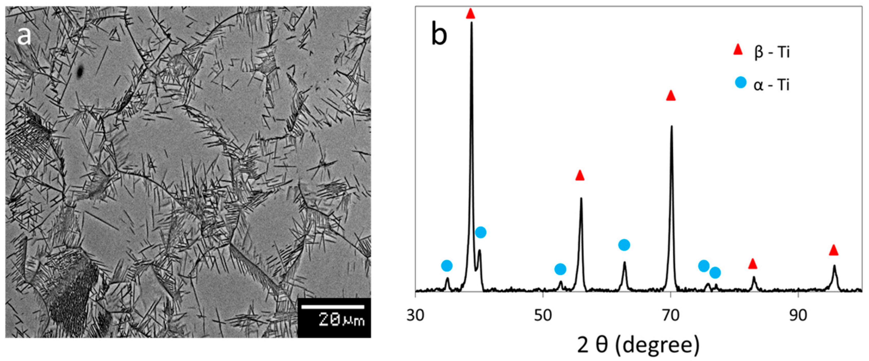
The solution treated and aged Ti-25Nb-3Mo-3Zr-2Sn alloy shown in Figure 1a with XRD phase analysis in b consists of β grains with grain sizes in the order of 50 μm and lath shaped α precipitates (the dark phase in the SEM image) located primarily around the grain boundaries and protruding into the β grains. Some α laths are also present within the interior of the β grains. The solution treated and aged alloy has a hardness of 265 ± 5 HV, an ultimate tensile strength of approximately 800 MPa with typical tensile elongation of around 8% [12].
3.2. Machining Chip Characteristics
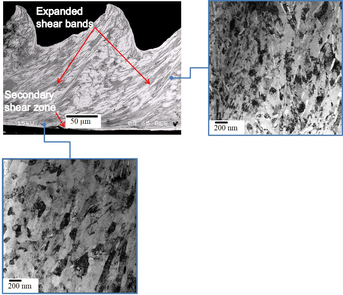
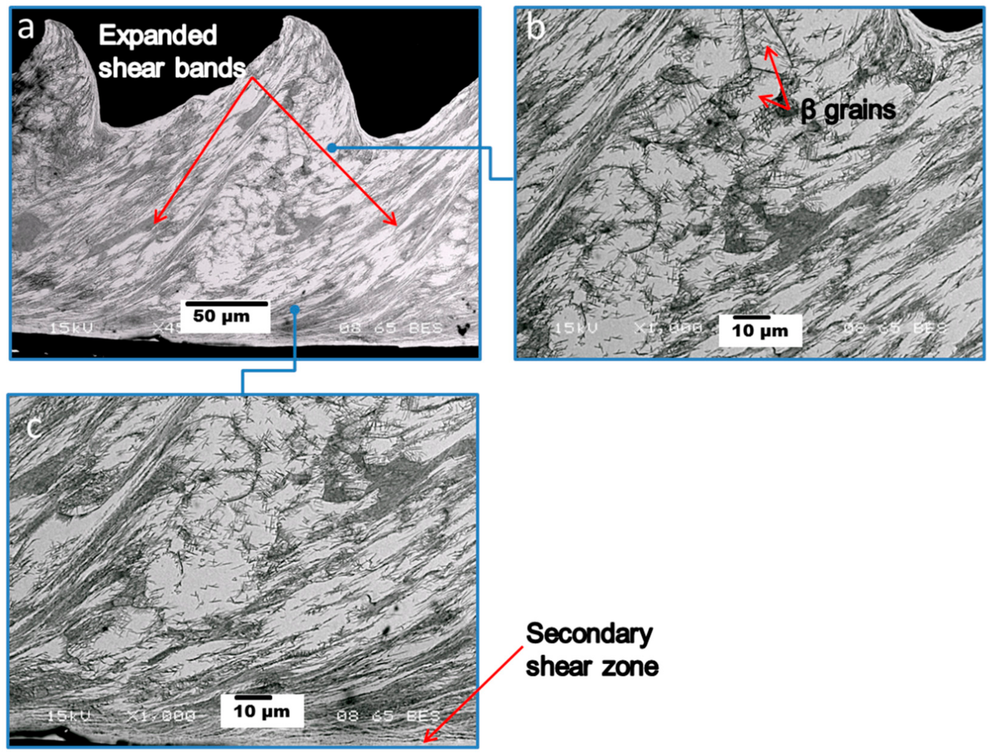
Cross-sections of Ti-25Nb-3Mo-3Zr-2Sn chips produced for cutting surface speeds of approximately 90 m/min are shown in Figure 2. Within this cutting regime the chips have segmented morphologies characterised by a serrated appearance with bands of severe plastic deformation, referred to herewith as expanded shear band regions, with more limited deformation in adjoining regions. According to previous research by the authors’, at these cutting speeds the undeformed chip surface length, i.e., the distance between the regions of severe deformation measured from the top surface of the chip, are approximately 0.08 mm while the average chip thickness is approximately 0.15 mm and the chip roughness ratio is around 0.2 [12,13].
The expanded shear band regions between the sawtooth chips feature extensive deformation as indicated in Figure 2a, while the regions outside these bands are subject to more limited deformation and the original β grain structure of the workpiece material remains discernable, examples of which are indicated in Figure 2b. Typical microhardness values measured from within the expanded shear band regions were 398 ± 15 HV, while adjoining regions with more limited deformation had hardness of around 292 ± 8 HV which is still substantially harder than the initial starting material (265 ± 5 HV). As is also the case for formation of continuous chips, during formation of segmented chips deformation of the material occurs ahead of the tool in the region referred to as the primary shear zone. The transition from continuous to segmented chip morphologies, featuring thermoplastic instability-induced shear banding, emerges once the smooth chip flow becomes insufficient to dissipate the energy through homogeneous plastic flow [17]. The other significant area of deformation in the chip is the secondary shear zone shown in Figure 2c, which is the region adjoining the tool rake face during cutting. Hardness measurements from within the secondary shear zone were around 363 ± 8 HV. However, it should be noted that the measurements were approximately 20 µm from the outer edge of the chip which was as near to the cutting interface as could be reliably tested through microhardness measurements.
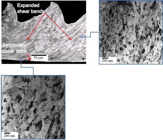
3.3. Transmission Electron Microscopy (TEM) Analysis of Expanded Shear Band Region
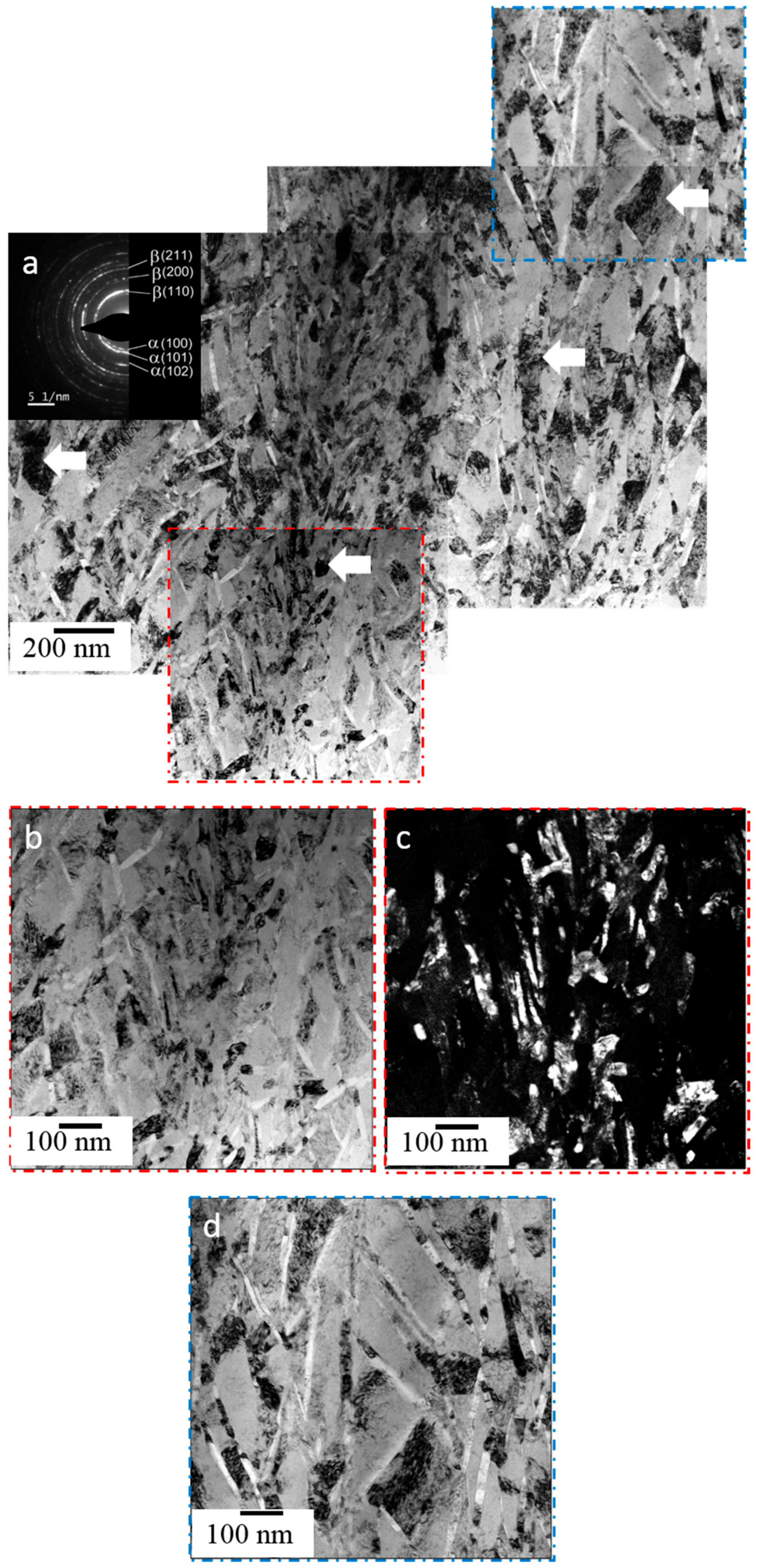
A montage of bright field (BF) TEM images showing the typical microstructure within the expanded shear band region is presented in Figure 3a and a selected area diffraction pattern (SADP) from this region is included inset. They reveal that the microstructure in the bands is highly refined, consisting of fine elongated β grains as the matrix phase interspersed with lath-like α precipitates (lighter contrast). The SAPD, indexed to the β and α phases, exhibits a continuous ring pattern characteristic of very fine and randomly oriented grains with large grain boundary misorientations. There is a gradient of deformation from the highly refined, smaller grains at the centre to more coarse grains at the left and right extremities. Some individual β grains can be identified (arrowed in Figure 3a) due to dark strain contrast arising from high levels of dislocation activity. The arrowed β grains reveal the progression of refinement from the extremities to the interior. The β grains at the extremities have a diamond-like shape with grain sizes in the order of 400–500 nm with α phase laths often sitting along their diagonal boundaries. Closer to the heavily refined central region, the β grains transition to an elongated form with grains around 20–50 nm in width and 300–400 nm in length, while the α laths with their long axis closely aligned to the length-wise axis of the β grains are 5–10 nm in width and 300–400 nm in length. In the most highly refined region, the β grain size is less than 100 nm.
Higher magnification BF and corresponding hollow cone dark field (HCDF) images from this highly refined region are presented in Figure 3b,c, respectively. They further reveal the fine β grains with considerable internal deformation structure as well as the lath-like α phase. A high magnification BF image showing the coarse diamond shaped β grains at the extremities of the deformation region is shown in Figure 3d.
3.4. TEM Analysis of Secondary Shear Zone
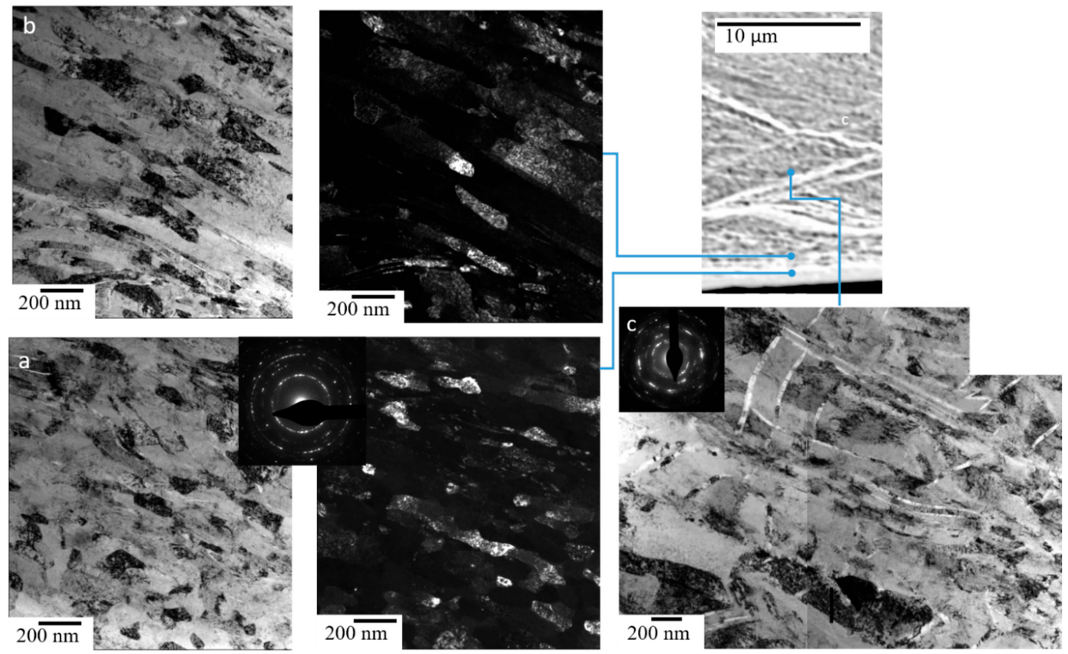
A series of TEM images from the secondary shear zone are presented in Figure 4. They reveal the chip microstructure in the region immediately adjacent to the rake face (a), i.e., at the chip extremity, and then moving incrementally into the chip interior, (b) and (c).
Figure 4a shows a BF TEM image with SADP inset and corresponding HCDF image from the region immediately adjacent to the rake face. The SADP exhibits a continuous ring pattern characteristic of very fine and randomly oriented grains with reflections from the β phase only. The BF image reveals a gradient of deformation from left to right from fine equiaxed grains immediately adjacent to the cutting interface at the left with grain sizes around 30–50 nm to more elongated grains 50 to 100 nm in width and several hundreds of nm in length at the right further from the cutting interface. A BF TEM image showing the significantly elongated β grains formed further from the cutting interface (approximately 1–2 µm) and a corresponding HCDF formed from the β (110) diffraction ring are shown in Figure 4b. Figure 4c reveals the microstructure in the secondary shear zone 5–10 µm from the cutting interface becomes less refined and consists of significantly larger, elongated β grains with long lath-like α precipitates (lighter contrast). Again, some β grains exhibit dark contrast arising from high levels of dislocation activity within their interiors. The SAPD from this region exhibits a discontinuous ring pattern indicative of a less refined structure with reflections from both the β and α phases.
4. Discussion
The TEM characterisation revealed important details of the machining chip microstructures which are linked to the deformation processes taking place in the chips during machining of the Ti-25Nb-3Mo-3Zr-2Sn alloy. Significant differences were identified between the expanded shear bands regions and the secondary shear zone which are discussed in respect to the influence of strain, heat generation and temperatures encountered during cutting.
High levels of deformation in the expanded shear bands formed within the primary deformation zone promote extensive localised refinement of the β phase to almost equiaxed grains with sizes below 100 nm. Additionally, α phase laths frequently occupy the β grain boundaries, aligned to the shear direction. This grain refinement consequently led to an approximate 50% increase in hardness from that of the starting material, primarily due to locally enhanced Hall-Petch strengthening [18]. In regions adjacent to the fine equiaxed zone, there is a transition to firstly larger elongated β grains, which according to the work of Zhan et al. [16] can be inferred to be the <001> and <111> fibre textures, with α laths aligned to the shear direction, and then to larger diamond shaped β grains with α phase often located on their diagonal axes. Across the entire width of the expanded shear band region, this variation in refinement suggests a cyclic process of formation such that the expanded shear band consists of an accumulation of individual localised shear events. The presence of both β and α phases across the entire expanded shear band region indicates that temperatures associated with adiabatic heating during cutting do not exceed the β transus temperature of around 720 °C for the Ti-25Nb-3Mo-3Zr-2Sn alloy [19]. The high density of α phase laths in this region suggest that dynamic precipitation may also take place in conjunction with the deformation. This suggests that temperatures during cutting are likely in the range of 400–600 °C [20].
Shear localisations are often observed in titanium alloys subject to dynamic loading associated with their low heat conductivity and high adiabatic shearing sensitivity [21]. Chip formation occurs by concentrated shear within the deformation band and the microstructural refinement is attributed to the large shear strains imposed. The formation of the shear regions is linked to substantial reductions in the yield stress which occur during cutting due to substantial thermal softening of the Ti-25Nb-3Mo-3Zr-2Sn alloy at elevated temperatures [16]. Under the momentum diffusion-based shear band evolution model, a highly localised primary shear band forms at the centre of the primary deformation zone and large deformation occurs inside the shear band as the localised shear deformation proceeds [22]. Subsequent thermal softening enables relaxation of the stress within the shear band and the stress relaxation further propagates into the surrounding undisturbed material giving rise to momentum diffusion and broadening of the deformation region as the expanded shear band regions evolve.
In comparison to the highly localised shear bands observed in cutting of other titanium alloys [23,24,25,26], the expanded shear band regions observed for the Ti-25Nb-3Mo-3Zr-2Sn alloy are relatively diffuse. Under the current cutting conditions, for the Ti-25Nb-3Mo-3Zr-2Sn alloy these zones are around 100 μm in width and of a similar magnitude to that of the regions with more limited deformation. An increase in hardness of around 10% from the starting material in regions between the expanded shear bands indicates that deformation in the primary shear zone is not entirely confined to the expanded shear band regions. Additionally, increased temperatures during cutting may also promote further α phase precipitation in these regions of more limited deformation which would also increase hardness.
For the secondary shear zone, strains at the cutting interface can be very large (>5) [27], typically leading to formation of ultrafine and/or nanocrystalline grain structures. The level of strain and hence refinement decays with increasing distance from the cutting interface across the secondary shear zone, which is in the order of 15–20 μm in width for the Ti-25Nb-3Mo-3Zr-2Sn alloy. At the cutting interface the β grains are heavily refined and approximately equiaxed with very fine nanocrystalline grain sizes around 20–50 nm while further from the interface, approximately 1–2 µm, the β grains become highly elongated in the shear direction with grains in the order of 100 nm in width and 0.5 to 1 μm in length. Again it can be inferred that the elongated grains are aligned to the <001> and <111> fibre textures [16]. An absence of the α phase in the equiaxed and elongated β grain regions of the secondary shear zone indicates that recrystallization takes place during cutting and temperatures are in excess of the alloy’s 720 °C β transus temperature while subsequent rates of cooling are sufficiently high to preserve the single phase β microstructure. At 5–10 µm from the cutting interface a mixture of larger elongated β grains and long α laths are observed and the hardness is enhanced by more than 30% over that of the starting material. This can be attributed to the effects of significant β phase refinement resulting from deformation during cutting which enhances Hall-Petch strengthening as well as dynamic precipitation taking place due to the elevated temperatures during cutting. The α laths tend to have thinner, longer morphologies than those observed within the expanded shear band region which is potentially due to the influence of comparatively higher temperatures and strains in this region, which favour growth of precipitates over nucleation through dynamic precipitation effects.
As the temperature and intensity of strain decrease across the secondary shear zone as a function of the distance from the cutting interface, the microstructures observed reflect their differing thermomechanical histories. The variations observed in the microstructure across the secondary deformation zone for the Ti-25Nb-3Mo-3Zr-2Sn alloy are largely consistent with those reported for adiabatic shear bands formed in titanium alloys [21,28,29] involving a progression to finer, more equiaxed grains in the region of most intense deformation, in this case at the cutting interface [14].
Previously, Rashid et al. [12] used infrared thermography to measure the maximum temperatures at the back surface of the chips in the cutting region during machining of the Ti-25Nb-3Mo-3Zr-2Sn alloy. They reported the average temperatures to be 540–600 °C for surface cutting speeds of 80–100 m/min for the solution treated and aged alloy. However, as the cutting edge was covered by the chip, the temperatures reported were those from the cutting zone at the external surface of the chip, i.e., on the opposite side to the cutting interface. Therefore, the actual temperature at the interface between the cutting face of the tool and the chip may be substantially higher than those reported. Additionally, infrared thermography temperature measurements are acknowledged to be subject to substantial error [30,31] and temperatures in the cutting zone are far from uniform, being typically characterised by regions of high temperature gradient [32,33]. The microstructural characterisation of the chips gives some insight into the degree of these temperature gradients for machining of the solution treated and aged Ti-25Nb-3Mo-3Zr-2Sn alloy. For the chip, the significant sources of heat are in the primary deformation zone due to plastic work associated with shear and in the secondary deformation zone due to work done in deformation of the chip and in association with sliding friction at the tool-chip interface.
Based on the assumption that all mechanical work is converted to heat, the cutting forces can be applied to estimate heat generation during cutting. In this case, the heat generated in the primary deformation zone, , can be calculated from [32]:
where FV is the tangential cutting force and V is the cutting velocity.
The amount of heat generated due to work done in the secondary deformation zone along the tool rake face is calculated from the frictional energy given by:
where is the total shear force acting on the rake face and λ is the chip thickness ratio. The shear force can be calculated from:
where is the feed force and α is the rake angle. An estimate of the heat generated in the primary and secondary deformation zone made from the above equations using the cutting forces reported by Rashid et.al. [12] with a tangential cutting force, , a feed force, , a cutting velocity, , a chip thickness ratio, and a rake angle α = 9°.yields heat generation of approximately 40 kW in the primary deformation zone and 22 kW in the secondary shear zone. From this analysis, the heat generated in the secondary shear zone for cutting of the Ti-25Nb-3Mo-3Zr-2Sn alloy is proportionately quite high at around 55% of that in the primary deformation zone. For context, Tay et al. observe that typically the total heat generation due to plastic deformation and frictional sliding in the secondary deformation zone for continuous chips from a non-abrasive material at medium cutting speeds is around 20% to 30% of the heat generated in the primary cutting zone [34].
While cutting heat is removed by the chip, the tool, the workpiece and some of the heat generated at the shear plane (primary shear zone) is transferred to the tool-chip interface. Hence, the temperature in the chip in the region adjacent to the tool rake face rises due to the combination of heat from the primary and secondary shear zones. Predictions of the temperature fields in the chip on the basis of heat generation are complex and have been the subject of various analytical and numerical investigations involving modelling of heat conduction, kinematics, geometries and energy aspects of the machining process. Others have attempted to measure temperature both at the cutting interface zone and across the chip, tool and workpiece through the methods including embedded thermocouples, radiation pyrometers and metallographic techniques [32,33]. In general, the highest temperatures are reportedly near the tool-chip interface in the secondary deformation zone. This is consistent with the microstructural analysis of the Ti-25Nb-3Mo-3Zr-2Sn alloy chips which indicated that temperatures in this region were in excess of 720 °C during cutting.
5. Conclusions
Ultrafine grain microstructures formed by severe plastic deformation during machining of the solution treated and aged Ti-25Nb-3Mo-3Zr-2Sn biomedical β titanium alloy have been investigated by TEM analyses of specimens obtained by FIB from transverse section of chips. The investigations have revealed that:
- High levels of deformation in the primary shear zone promote extensive refinement of the β phase within expanded shear band regions approximately 100 µm in width to almost equiaxed grains with sizes below 100 nm in regions of intense deformation, while α phase laths frequently occupy the grain boundaries aligned to the shear direction. There is a transition to firstly elongated β grains and then to larger diamond-shaped β grains in adjoining regions of less intense deformation. The presence of a high density of α phase laths across the entire expanded shear band region suggests that temperatures in this region are likely in the range of 400–600 °C during cutting.
- For the secondary shear zone, large strains at the cutting interface result in recrystallised, approximately equiaxed grains with nanocrystalline grain sizes around 20–50 nm, while further (1–2 µm) from the interface the β grains become highly elongated in the shear direction with grains in the order of 100 nm in width and 0.5 to 1 μm in length. At the cutting interface, an absence of the α phase indicates that the temperatures exceed the alloy’s 720 °C β transus temperature. At 5–10 µm, from the cutting interface a mixture of large elongated β grains and long α phase laths are observed. The microstructural variation across the secondary shear zone reflects the decay of strain and temperature away from the cutting interface.
- The microstructural characterisation of the chips infers information on the temperature fields present across the chips during cutting. The highest cutting temperatures occur within the secondary shear zone at the cutting interface, associated with proportionately high levels of heat generation due to deformation and friction.
Author Contributions
Conceptualization, D.K., M.D., S.S. and M.B.; Methodology, D.K.; Investigation, D.K., R.R.R. and H.A.; Writing-Original Draft Preparation, D.K.; Writing-Review & Editing, R.R.R., M.B. and S.S.; Project Administration, M.D.; Funding Acquisition, D.K. M.B. and M.D.
Funding
This research was funded by the Australian Research Council (ARC) Research Hub for Advanced Manufacturing of Medical Devices (IH150100024).
Acknowledgments
The authors acknowledge the facilities, and the scientific and technical assistance of the Australian Microscopy & Microanalysis Research Facility at the Centre for Microscopy and Microanalysis, The University of Queensland and at the Australian Centre for Microscopy & Microanalysis at the University of Sydney.
Conflicts of Interest
The authors declare no conflict of interest.
References
- Long, M.; Rack, H.J. Titanium alloys in total joint replacement—A materials science perspective. Biomaterials 1998, 19, 1621–1639. [Google Scholar] [CrossRef]
- Niinomi, M. Mechanical biocompatabilities of titanium alloys for biomedical applications. J. Mech. Behav. Biomed. Mater. 2008, 1, 30–42. [Google Scholar] [CrossRef] [PubMed]
- Ping, D.H.; Mitarai, Y.; Yin, F.X. Microstructure and shape memory behavior of a Ti-30Nb-3Pd alloy. Scr. Mater. 2005, 52, 1287–1291. [Google Scholar] [CrossRef]
- Yu, Z.; Wang, G.; Ma, X.Q.; Dargusch, M.S.; Han, J.Y.; Yu, S. Development of biomedical near beta titanium alloys. In Materials Science Forum: 4th International Light Metals Technology Conference; Trans Tech Publications: Zurich, Switzerland, 2009. [Google Scholar]
- Kent, D.; Wang, G.; Yu, Z.; Dargusch, M.S. Pseudoelastic behaviour of a β Ti-25Nb-3Zr-3Mo-2Sn alloy. Mater. Sci. Eng. A 2010, 527, 2246–2252. [Google Scholar] [CrossRef]
- Kent, D.; Wang, G.; Yu, Z.; Ma, X.; Dargusch, M.S. Strength enhancement of a biomedical titanium alloy through a modified accumulative roll bonding technique. J. Mech. Behav. Biomed. Mater. 2011, 4, 405–416. [Google Scholar] [CrossRef] [PubMed]
- Rahman, M.; Wong, Y.S.; Zareena, A.R. Machinability of titanium alloys. JSME Int. J. Ser. C 2003, 46, 107–115. [Google Scholar] [CrossRef]
- Yang, X.; Liu, C.R. Machining titanium and its alloys. Mach. Sci. Technol. 1999, 3, 107–139. [Google Scholar] [CrossRef]
- Ezugwu, E.O.; Wang, Z.M. Titanium alloys and their machinability—A review. J. Mater. Process. Technol. 1997, 68, 262–274. [Google Scholar] [CrossRef]
- Machado, A.R.; Wallbank, J. Machining of titanium and its alloys—A review. Proc. Inst. Mech. Eng. Part B 1990, 204, 53–60. [Google Scholar] [CrossRef]
- Uzer, B.; Toker, S.M.; Cingoz, A.; Bagci-Onder, T.; Gerstein, G.; Maier, H.J.; Canadinc, D. An exploration of plastic deformation dependence of cell viability and adhesion in metallic implant materials. J. Mech. Behav. Biomed. Mater. 2016, 60, 177–186. [Google Scholar] [CrossRef] [PubMed]
- Rashid, R.A.R.; Sun, S.; Wang, G.; Dargusch, M.S. Machinability of a near beta titanium alloy. Proc. Inst. Mech. Eng. Part B 2011, 225, 2151–2162. [Google Scholar] [CrossRef]
- Rashid, R.A.R.; Sun, S.; Wang, G.; Dargusch, M.S. Experimental investigation of various chip parameters during machining of the Ti25Nb3Mo3Zr2Sn beta titanium alloy. Adv. Mat. Res. 2013, 622, 366–369. [Google Scholar] [CrossRef]
- Schneider, J.; Dong, L.; Howe, J.Y.; Meyer, H.M. Microstructural characterization of Ti-6Al-4V metal chips by focused ion beam and transmission electron microscopy. Metall. Mater. Trans. A 2011, 42, 3527–3533. [Google Scholar] [CrossRef]
- Zhan, H.; Zeng, W.; Wang, G.; Kent, D.; Dargusch, M. On the deformation mechanisms and strain rate sensitivity of a metastable β Ti-Nb alloy. Scr. Mater. 2015, 107, 34–37. [Google Scholar] [CrossRef]
- Zhan, H.; Wang, G.; Kent, D.; Dargusch, M. The dynamic response of a metastable β Ti-Nb alloy to high strain rates at room and elevated temperatures. Acta Mater. 2016, 105, 104–113. [Google Scholar] [CrossRef]
- Ye, G.G.; Xue, S.F.; Ma, W.; Dai, L.H. Onset and evolution of discontinuously segmented chip flow in ultra-high-speed cutting Ti-6Al-4V. Int. J. Adv. Manuf. Technol. 2017, 88, 1161–1174. [Google Scholar] [CrossRef]
- Hughes, G.D.; Smith, S.D.; Pande, C.S.; Johnson, H.R.; Armstrong, R.W. Hall-petch strengthening for the microhardness of twelve nanometer grain diameter electrodeposited nickel. Scr. Metall. 1986, 20, 93–97. [Google Scholar] [CrossRef]
- Zhentao, Y.; Lian, Z. Influence of martensitic transformation on mechanical compatibility of biomedical β type titanium alloy tlm. Mater. Sci. Eng. A 2006, 438, 391–394. [Google Scholar] [CrossRef]
- Kent, D.; Pas, S.; Zhu, S.; Wang, G.; Dargusch, M.S. Thermal analysis of precipitation reactions in a Ti–25nb–3mo–3zr–2sn alloy. Appl. Phys. A 2012, 107, 835–841. [Google Scholar] [CrossRef]
- Wang, B.; Wang, X.; Li, Z.; Ma, R.; Zhao, S.; Xie, F.; Zhang, X. Shear localization and microstructure in coarse grained beta titanium alloy. Mater. Sci. Eng. A 2016, 652, 287–295. [Google Scholar] [CrossRef]
- Ye, G.G.; Xue, S.F.; Jiang, M.Q.; Tong, X.H.; Dai, L.H. Modeling periodic adiabatic shear band evolution during high speed machining Ti-6Al-4V alloy. Int. J. Plast. 2013, 40, 39–55. [Google Scholar] [CrossRef]
- Arrazola, P.J.; Garay, A.; Iriarte, L.M.; Armendia, M.; Marya, S.; Le Maître, F. Machinability of titanium alloys (Ti6Al4V and Ti555.3). J. Mater. Process. Technol. 2009, 209, 2223–2230. [Google Scholar] [CrossRef]
- Joshi, S.; Pawar, P.; Tewari, A.; Joshi, S.S. Effect of β phase fraction in titanium alloys on chip segmentation in their orthogonal machining. CIRP J. Manuf. Sci. Technol. 2014, 7, 191–201. [Google Scholar] [CrossRef]
- Sun, S.; Brandt, M.; Dargusch, M.S. Characteristics of cutting forces and chip formation in machining of titanium alloys. Int. J. Mach. Tool. Manuf. 2009, 49, 561–568. [Google Scholar] [CrossRef]
- Dargusch, M.S.; Sun, S.; Kim, J.W.; Li, T.; Trimby, P.; Cairney, J. Effect of tool wear evolution on chip formation during dry machining of ti-6al-4v alloy. Int. J. Adv. Manuf. Tech. 2018, 126, 13–17. [Google Scholar] [CrossRef]
- Oxley, P.L.B. Mechanics of Machining; Ellis Horwood: New York, NY, USA, 1989. [Google Scholar]
- Zhan, H.; Zeng, W.; Wang, G.; Kent, D.; Dargusch, M. Microstructural characteristics of adiabatic shear localization in a metastable beta titanium alloy deformed at high strain rate and elevated temperatures. Mater. Charact. 2015, 102, 103–113. [Google Scholar] [CrossRef]
- Yang, Y.; Jiang, F.; Zhou, B.M.; Li, X.M.; Zheng, H.G.; Zhang, Q.M. Microstructural characterization and evolution mechanism of adiabatic shear band in a near beta-ti alloy. Mater. Sci. Eng. A 2011, 528, 2787–2794. [Google Scholar] [CrossRef]
- Davies, M.A.; Ueda, T.; M’Saoubi, R.; Mullany, B.; Cooke, A.L. On the measurement of temperature in material removal processes. CIRP Ann. Manuf. Technol. 2007, 56, 581–604. [Google Scholar] [CrossRef]
- Lane, B.; Whitenton, E.; Madhavan, V.; Donmez, A. Uncertainty of temperature measurements by infrared thermography for metal cutting applications. Metrologia 2013, 50, 637–653. [Google Scholar] [CrossRef]
- Abukhshim, N.A.; Mativenga, P.T.; Sheikh, M.A. Heat generation and temperature prediction in metal cutting: A review and implications for high speed machining. Int. J. Mach. Tool. Manuf. 2006, 46, 782–800. [Google Scholar] [CrossRef]
- Sutter, G.; Ranc, N. Temperature fields in a chip during high-speed orthogonal cutting—an experimental investigation. Int. J. Mach. Tool. Manuf. 2007, 47, 1507–1517. [Google Scholar] [CrossRef]
- Tay, A.O.; Stevenson, M.G.; De Vahl Davis, G. Using the finite element method to determine temperature distributions in orthogonal machining. Proc. Inst. Mech. Eng. 1974, 188, 627–638. [Google Scholar] [CrossRef]
Figure 1.
Scanning electron microscopy (SEM) image (a) and X-ray diffraction (XRD) spectrum (b) from the solution treated and aged workpiece material.
Figure 1.
Scanning electron microscopy (SEM) image (a) and X-ray diffraction (XRD) spectrum (b) from the solution treated and aged workpiece material.

Figure 2.
SEM of machining chip microstructure for surface cutting speed around 90 m/min: (a) Low magnification image of segmented chip morphology. (b) Undeformed chip region with original β grain structure of the workpiece material with in-tact β grains highlighted. (c) Higher magnification image of the secondary shear zone which adjoins the tool rake face during cutting.

Figure 3.
Transmission electron microscopy (TEM) from the expanded shear band region: (a) Montage of bright field (BF) images with selected area diffraction pattern (SADP) inset indexed to the β and α phases. (b) BF image and (c) corresponding hollow cone dark field (HCDF) image from the red dashed region in (a) formed from β (110) and α (100), (002), (101) diffraction rings. (d) Higher magnification BF image from the blue dashed region in (a).

Figure 4.
Series of TEM images from the secondary shear zone region immediately adjacent to the rake face (a), i.e., the chip extremity, and incrementally further into the chip interior (b,c). (a) BF image with SADP inset showing reflections almost entirely from the β phase and corresponding HCDF image formed from the β (110) diffraction ring. (b) BF image and corresponding HCDF image formed from β (110) diffraction ring. (c) Montage of BF images with SADP inset with reflections from the β and α phases.

© 2018 by the authors. Licensee MDPI, Basel, Switzerland. This article is an open access article distributed under the terms and conditions of the Creative Commons Attribution (CC BY) license (http://creativecommons.org/licenses/by/4.0/).
Share and Cite
MDPI and ACS Style
Kent, D.; Rahman Rashid, R.; Bermingham, M.; Attar, H.; Sun, S.; Dargusch, M. Insights into Machining of a β Titanium Biomedical Alloy from Chip Microstructures. Metals 2018, 8, 710. https://doi.org/10.3390/met8090710
AMA Style
Kent D, Rahman Rashid R, Bermingham M, Attar H, Sun S, Dargusch M. Insights into Machining of a β Titanium Biomedical Alloy from Chip Microstructures. Metals. 2018; 8(9):710. https://doi.org/10.3390/met8090710
Chicago/Turabian StyleKent, Damon, Rizwan Rahman Rashid, Michael Bermingham, Hooyar Attar, Shoujin Sun, and Matthew Dargusch. 2018. "Insights into Machining of a β Titanium Biomedical Alloy from Chip Microstructures" Metals 8, no. 9: 710. https://doi.org/10.3390/met8090710
Note that from the first issue of 2016, this journal uses article numbers instead of page numbers. See further details here.